Emulator of a Boost Converter for Educational Purposes


Abstract
1. Introduction
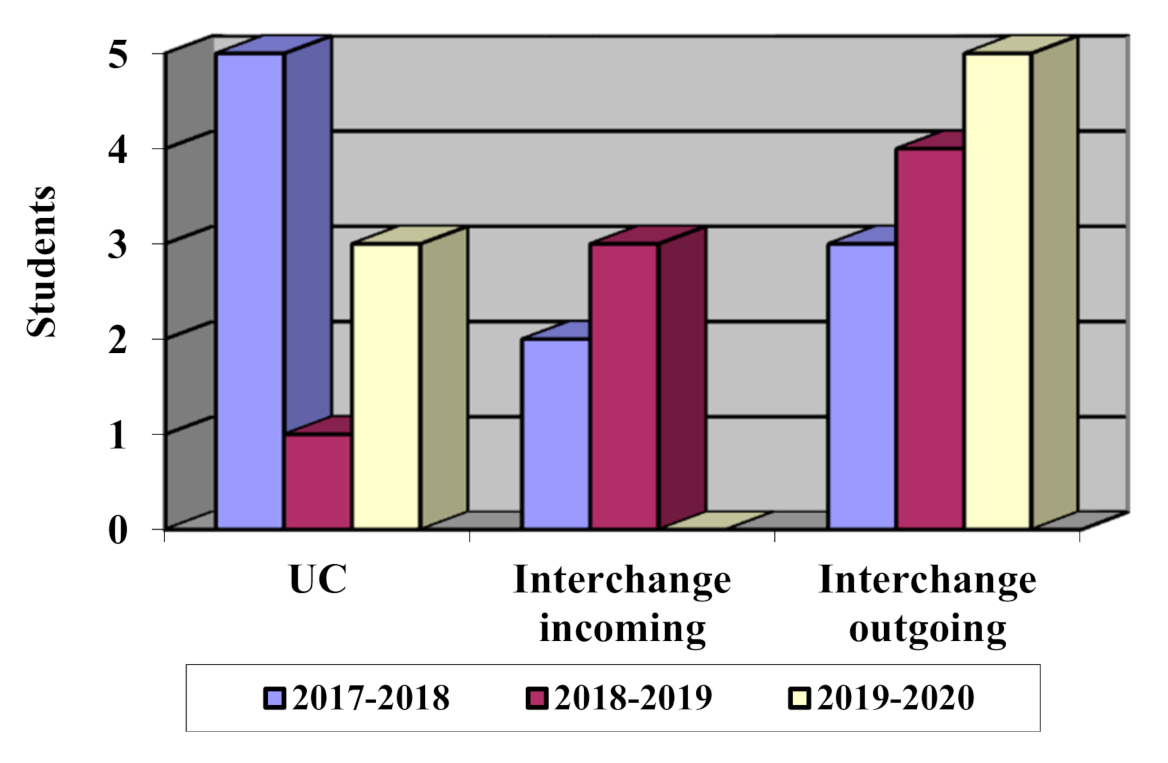
2. Context
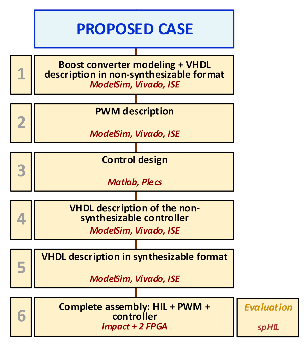
3. Teaching Organization of the Case Study
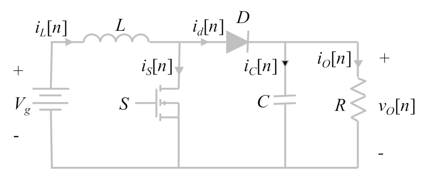
3.1. Boost Converter Modeling
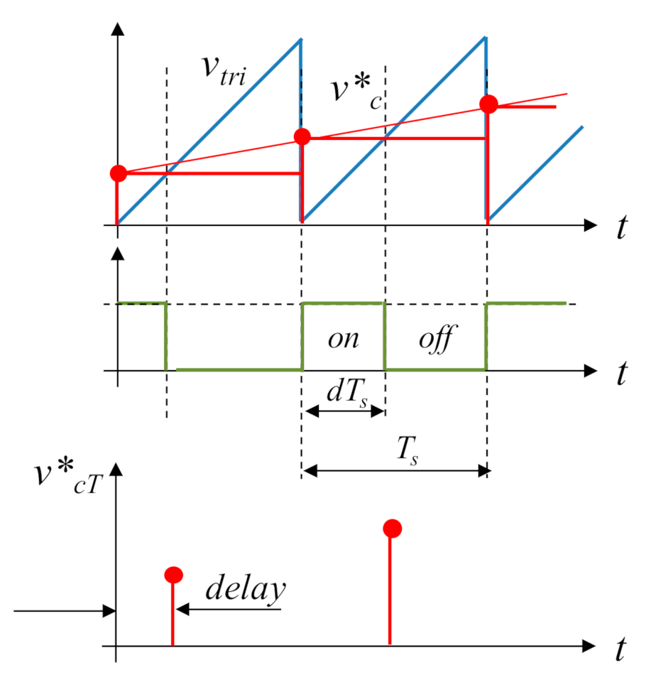
3.2. PWM
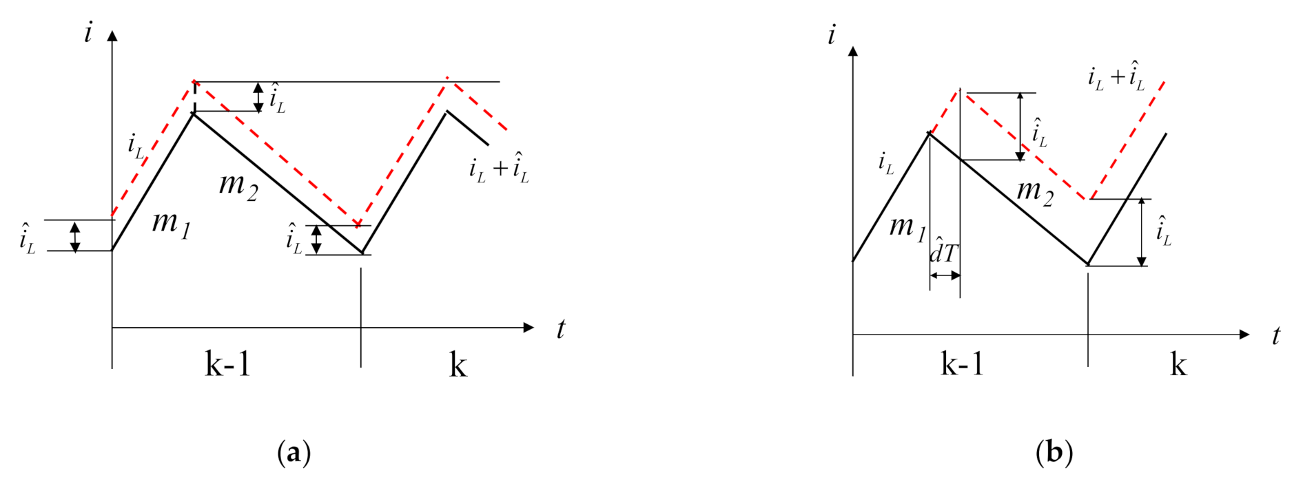
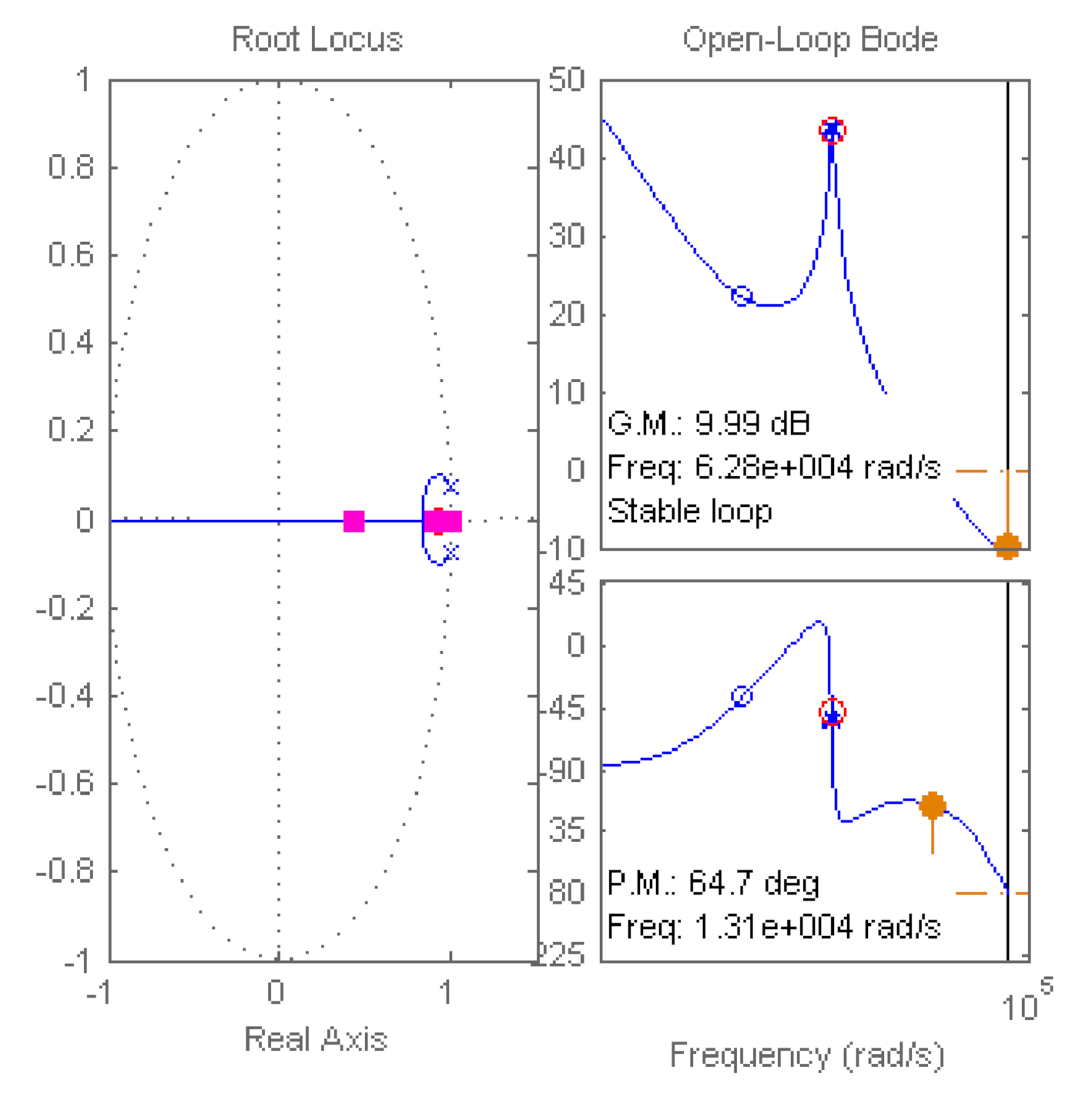
3.3. Control Design
3.4. VHDL Description of Non-Synthesizable Controller
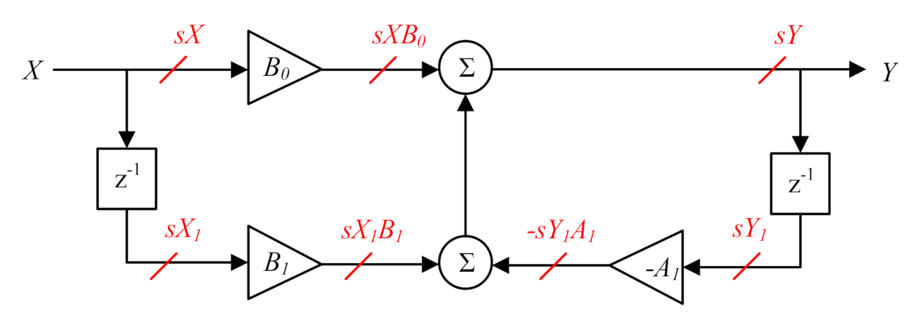
3.5. VHDL Description in Synthesizable Format
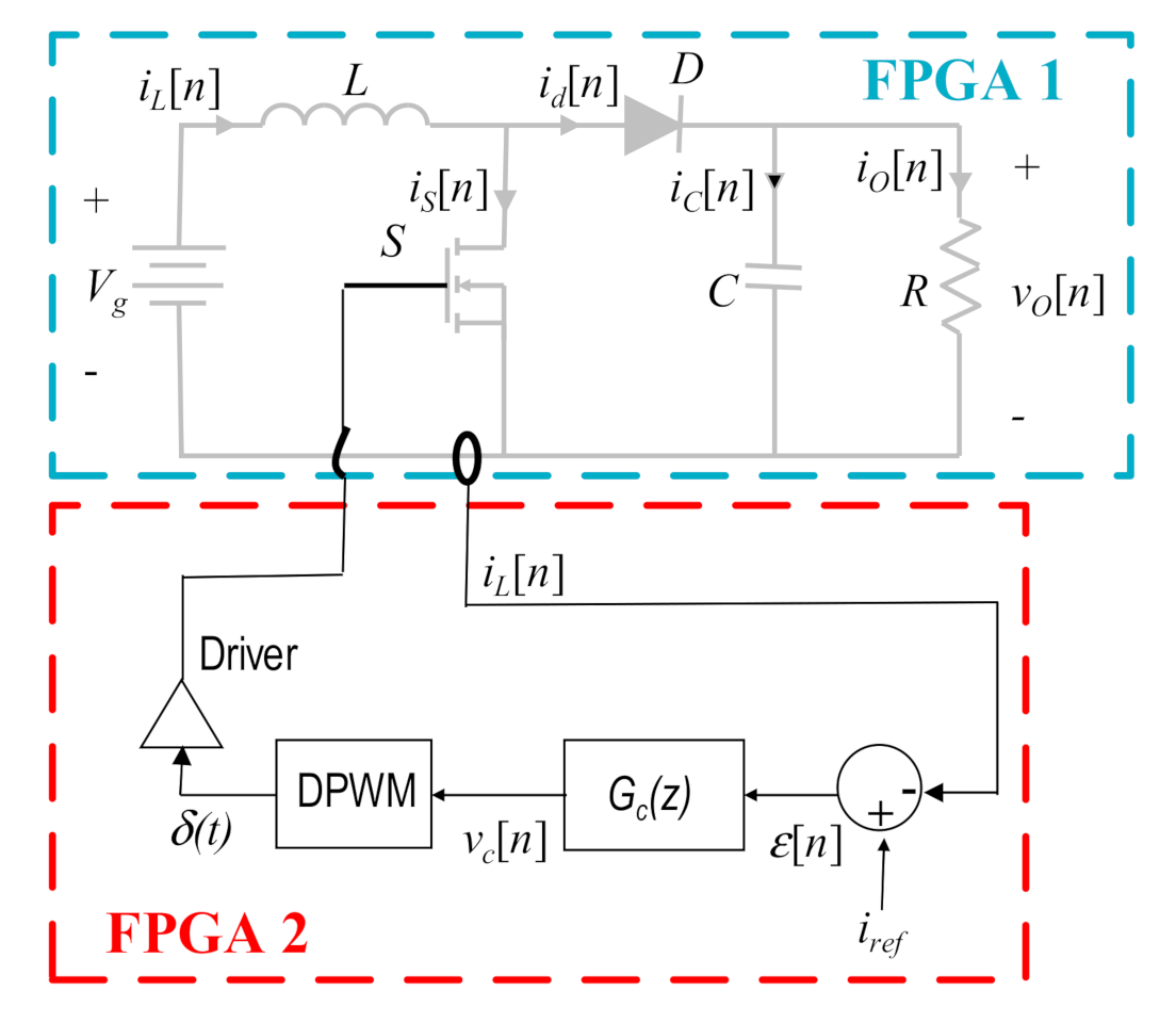
3.6. Complete Assembly (Hardware-in-the-Loop + PWM + Controller)
3.7. Evaluation
- no satisfactory solution—fail;
- simulation of the basic performance—C;
- implementation in FPGA and functional verification—B;
- verification of the circuit performance using HIL technique—A.
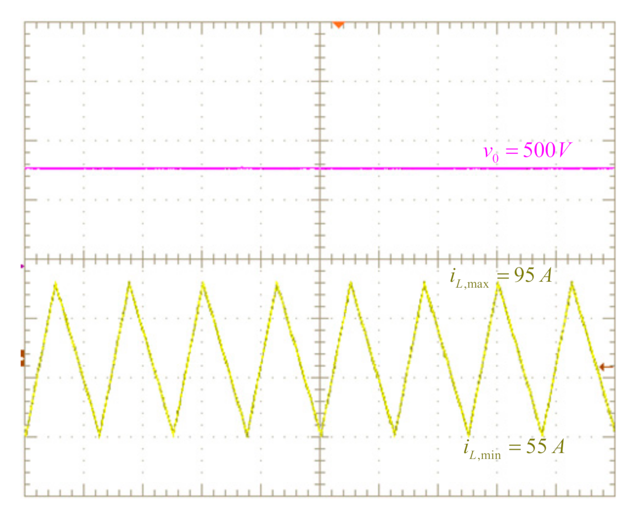
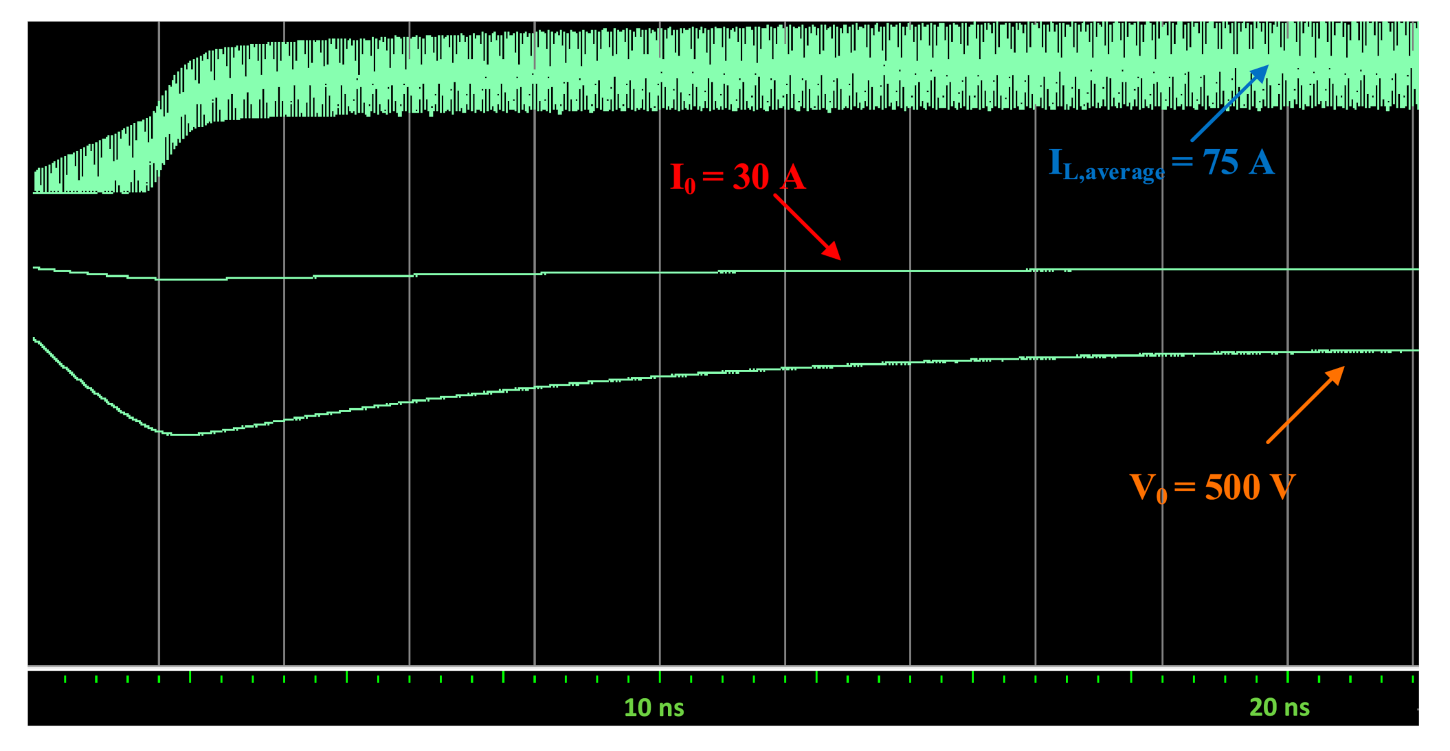
4. Results Obtained
5. Conclusions
Author Contributions
Funding
Acknowledgments
Conflicts of Interest
References
- Zhang, Z.; Hansen, C.T.; Andersen, M.A.E. Teaching Power Electronics With a Design-Oriented, Project-Based Learning Method at the Technical University of Denmark. IEEE Trans. Educ. 2016, 59, 32–38. [Google Scholar] [CrossRef]
- Chu, R.H.; Minasian, R.A.; Yi, X. Inspiring Student Learning in ICT Communications Electronics through a New Integrated Project-Based Learning Approach. J. Electr. Eng. Educ. 2012, 49, 127–135. [Google Scholar] [CrossRef]
- Fernandes, M.A. Project-based learning applied to an embedded systems course. J. Electr. Eng. Educ. 2017, 54, 223–235. [Google Scholar] [CrossRef]
- Chu, R.H.; Lu, D.D.-C.; Sathiakumar, S. Project-Based Lab Teaching for Power Electronics and Drives. IEEE Trans. Educ. 2008, 51, 108–113. [Google Scholar] [CrossRef]
- Martinez, F.; Herrero, L.C.; de Pablo, S. Project-Based Learning and Rubrics in the Teaching of Power Supplies and Photovoltaic Electricity. IEEE Trans. Educ. 2011, 54, 87–96. [Google Scholar] [CrossRef]
- Lamar, D.G.; Miaja, P.F.; Arias, M.; Rodriguez, A.; Rodriguez, M.; Vazquez, A.; Hernando, M.M.; Sebastian, J. Experiences in the Application of Project-Based Learning in a Switching-Mode Power Supplies Course. IEEE Trans. Educ. 2012, 55, 69–77. [Google Scholar] [CrossRef]
- Martinez-Rodrigo, F.; Herrero-De Lucas, L.C.; de Pablo, S.; Rey-Boue, A.B. Using PBL to Improve Educational Outcomes and Student Satisfaction in the Teaching of DC/DC and DC/AC Converters. IEEE Trans. Educ. 2017, 60, 229–237. [Google Scholar] [CrossRef]
- Zhu, J.; Liu, R.; Liu, Q.; Zheng, T.; Zhang, Z. Engineering Students’ Epistemological Thinking in the Context of Project-Based Learning. IEEE Trans. Educ. 2019, 62, 188–198. [Google Scholar] [CrossRef]
- Ghosh, S.; Giambiasi, N. Modeling and simulation of mixed-signal electronic designs-Enabling analog and discrete subsystems to be represented uniformly within a single framework. IEEE Circuits Devices Mag. 2006, 22, 47–52. [Google Scholar] [CrossRef]
- Pecheux, F.; Lallement, C.; Vachoux, A. VHDL-AMS and Verilog-AMS as alternative hardware description languages for efficient modeling of multidiscipline systems. IEEE Trans. Comput. Aided Des. Integr. Circuits Syst. 2005, 24, 204–225. [Google Scholar] [CrossRef]
- Lucía, Ó.; Urriza, I.; Barragán, L.A.; Navarro, D.; Jiménez, Ó.; Burdío, J.M. Real-Time FPGA-Based Hardware-in-the-Loop Simulation Test Bench Applied to Multiple-Output Power Converters. IEEE Trans. Ind. Appl. 2011, 47, 853–860. [Google Scholar] [CrossRef]
- Sanchez, A.; de Castro, A.; Garrido, J. A Comparison of Simulation and Hardware-in-the-Loop Alternatives for Digital Control of Power Converters. IEEE Trans. Ind. Inform. 2012, 8, 491–500. [Google Scholar] [CrossRef]
- De Farias, A.B.C.; Rodrigues, R.S.; Murilo, A.; Lopes, R.V.; Avila, S. Low-Cost Hardware-in-the-Loop Platform for Embedded Control Strategies Simulation. IEEE Access 2019, 7, 111499–111512. [Google Scholar] [CrossRef]
- Larruscain, G.; Tapia, G.; Susperregui, A.; Martinez, M.I. Student-tailored final year project on microcontroller-based hardware-in-the-loop speed control of a wind generator. J. Electr. Eng. Educ. 2018, 55, 213–233. [Google Scholar] [CrossRef]
- Ahmad, Z.; Torres, J.R.; Veera Kumar, N.; Rakhshani, E.; Palensky, P.; van der Meijden, M. A Power Hardware-in-the-Loop Based Method for FAPR Compliance Testing of the Wind Turbine Converters Control. Energies 2020, 13, 5203. [Google Scholar] [CrossRef]
- Kotsampopoulos, P.C.; Kleftakis, V.A.; Hatziargyriou, N.D. Laboratory Education of Modern Power Systems Using PHIL Simulation. IEEE Trans. Power Syst. 2017, 32, 3992–4001. [Google Scholar] [CrossRef]
- Mascio, C.D.; Gruosso, G. Hardware in the Loop Implementation of the Oscillator-based Heart Model: A Framework for Testing Medical Devices. Electronics 2020, 9, 571. [Google Scholar] [CrossRef]
- Temeltas, H.; Gokasan, M.; Bogosyan, S.; Kilic, A. Hardware in the loop simulation of robot manipulators through Internet in mechatronics education. In Proceedings of the IEEE 2002 28th Annual Conference of the Industrial Electronics Society, Sevilla, Spain, 5–8 November 2002; Volume 4, pp. 2617–2622. [Google Scholar]
- García-Martínez, E.; Sanz, J.F.; Muñoz-Cruzado, J.; Perié, J.M. A Review of PHIL Testing for Smart Grids—Selection Guide, Classification and Online Database Analysis. Electronics 2020, 9, 382. [Google Scholar] [CrossRef]
- El Mariachet, J.; Guan, Y.; Matas, J.; Martín, H.; Li, M.; Guerrero, J.M. HIL-Assessed Fast and Accurate Single-Phase Power Calculation Algorithm for Voltage Source Inverters Supplying to High Total Demand Distortion Nonlinear Loads. Electronics 2020, 9, 1643. [Google Scholar] [CrossRef]
- Sankaranarayanan, V.; Shirazi, M.; Gao, Y.; Ghosh, A.; Erickson, R.W.; Maksimovic, D. Controller Hardware-in-the-Loop Validation of a Modular Control Architecture for a Composite DC-DC Converter. In Proceedings of the 2019 20th Workshop on Control and Modeling for Power Electronics (COMPEL), Toronto, ON, Canada, 17–20 June 2019; pp. 1–7. [Google Scholar]
- Saralegui, R.; Sanchez, A.; Martínez-García, M.S.; Novo, J.; Castro, A. de Comparison of Numerical Methods for Hardware-In-the-Loop Simulation of Switched-Mode Power Supplies. In Proceedings of the 2018 IEEE 19th Workshop on Control and Modeling for Power Electronics (COMPEL), Padova, Italy, 25–28 June 2018; pp. 1–6. [Google Scholar]
- Woods, R.; McAllister, J.; Lightbody, G.; Yi, Y. FPGA-Based Implementation of Signal. Processing Systems, 2nd ed.; John Wiley & Sons Inc: Hoboken, NJ, USA, 2017; ISBN 978-1-119-07795-4. [Google Scholar]
- Jandaghi, B.; Dinavahi, V. Hardware-in-the-Loop Emulation of Linear Induction Motor Drive for MagLev Application. IEEE Trans. Plasma Sci. 2016, 44, 679–686. [Google Scholar] [CrossRef]
- Parma, G.G.; Dinavahi, V. Real-Time Digital Hardware Simulation of Power Electronics and Drives. IEEE Trans. Power Deliv. 2007, 22, 1235–1246. [Google Scholar] [CrossRef]
- Matar, M.; Iravani, R. FPGA Implementation of the Power Electronic Converter Model for Real-Time Simulation of Electromagnetic Transients. IEEE Trans. Power Deliv. 2010, 25, 852–860. [Google Scholar] [CrossRef]
- Montano, F.; Ould-Bachir, T.; David, J.P. An Evaluation of a High-Level Synthesis Approach to the FPGA-Based Submicrosecond Real-Time Simulation of Power Converters. IEEE Trans. Ind. Electron. 2018, 65, 636–644. [Google Scholar] [CrossRef]
- Martínez-García, M.S.; de Castro, Á.; Sanchez, A.; Garrido, J. Word Length Selection Method for HIL power converter models. Int. J. Electr. Power Energy Syst. 2021. submitted. [Google Scholar]
- Sanchez, A.; de Castro, A.; Garrido, J. Parametrizable Fixed-Point Arithmetic for HIL With Small Simulation Steps. IEEE J. Emerg. Sel. Top. Power Electron. 2019, 7, 2467–2475. [Google Scholar] [CrossRef]
- Goñi, O.; Sanchez, A.; Todorovich, E.; Castro, A. de Resolution Analysis of Switching Converter Models for Hardware-in-the-Loop. IEEE Trans. Ind. Inform. 2014, 10, 1162–1170. [Google Scholar] [CrossRef]
- Jia, J.; Yang, G.; Nielsen, A.H.; Roenne-Hansen, P. Hardware-in-the-loop tests on distance protection considering VSC fault-ride-through control strategies. J. Eng. 2018, 2018, 824–829. [Google Scholar] [CrossRef]
- Vu, P.; Nguyen, Q.; Tran, M.; Todeschini, G.; Santoso, S. Adaptive backstepping approach for dc-side controllers of Z-source inverters in grid-tied PV system applications. IET Power Electron. 2018, 11, 2346–2354. [Google Scholar] [CrossRef]
- Amin, M.; Aziz, G.A.A.; Durkin, J.; Mohammed, O.A. A Hardware-in-the-Loop Realization of Speed Sensorless Control of PMa-SynRM With Steady-State and Transient Performances Enhancement. IEEE Trans. Ind. Appl. 2019, 55, 5331–5342. [Google Scholar] [CrossRef]
- Tian, J.; Liu, J.; Shu, J.; Tang, J.; Yang, J. Engineering modelling of wind turbine applied in real-time simulation with hardware-in-loop and optimising control. IET Power Electron. 2018, 11, 2490–2498. [Google Scholar] [CrossRef]
- Shiakolas, P.S.; Van Schenck, S.R.; Piyabongkarn, D.; Frangeskou, I. Magnetic levitation hardware-in-the-loop and MATLAB-based experiments for reinforcement of neural network control concepts. IEEE Trans. Educ. 2004, 47, 33–41. [Google Scholar] [CrossRef]
- Rasheduzzaman, M.; Chowdhury, B.H.; Bhaskara, S. Converting an Old Machines Lab Into a Functioning Power Network With a Microgrid for Education. IEEE Trans. Power Syst. 2014, 29, 1952–1962. [Google Scholar] [CrossRef]
- Tang, J.; Xiong, B.; Yang, C.; Tang, C.; Li, Y.; Su, G.; Bian, X. Development of an Integrated Power Distribution System Laboratory Platform Using Modular Miniature Physical Elements: A Case Study of Fault Location. Energies 2019, 12, 3780. [Google Scholar] [CrossRef]
- Mirinejad, H.; Parvinian, B.; Ricks, M.; Zhang, Y.; Weininger, S.; Hahn, J.; Scully, C.G. Evaluation of Fluid Resuscitation Control Algorithms via a Hardware-in-the-Loop Test Bed. IEEE Trans. Biomed. Eng. 2020, 67, 471–481. [Google Scholar] [CrossRef] [PubMed]
- Osen, O.L. On the Use of Hardware-in-the-Loop for Teaching Automation Engineering. In Proceedings of the 2019 IEEE Global Engineering Education Conference (EDUCON), Dubai, UAE, 8–11 April 2019; pp. 1308–1315. [Google Scholar]
- Grega, W. Hardware-in-the-loop simulation and its application in control education. In Proceedings of the FIE’99 Frontiers in Education, 29th Annual Frontiers in Education Conference, Designing the Future of Science and Engineering Education, San Juan, PR, USA, 10–13 November 1999; Volume 2, p. 12. [Google Scholar]
- Azcondo, F.J.; de Castro, A.; Brañas, C. Course on Digital Electronics Oriented to Describing Systems in VHDL. IEEE Trans. Ind. Electron. 2010, 57, 3308–3316. [Google Scholar] [CrossRef]
- Maksimovic, D. Computer-aided small-signal analysis based on impulse response of DC/DC switching power converters. IEEE Trans. Power Electron. 2000, 15, 1183–1191. [Google Scholar] [CrossRef]
- Maksimovic, D.; Zane, R. Small-Signal Discrete-Time Modeling of Digitally Controlled PWM Converters. IEEE Trans. Power Electron. 2007, 22, 2552–2556. [Google Scholar] [CrossRef]
- Corradini, L. Analysis and Implementation of Digital Control Architectures for DC-DC Switching Converters. Ph.D. Thesis, University of Padova, Padua, Italy, 2008. [Google Scholar]
- Peterchev, A.V.; Sanders, S.R. Quantization resolution and limit cycling in digitally controlled PWM converters. IEEE Trans. Power Electron. 2003, 18, 301–308. [Google Scholar] [CrossRef]
- Van de Sype, D.M.; De Gusseme, K.; Van den Bossche, A.P.; Melkebeek, J.A. Small-signal Laplace-domain analysis of uniformly-sampled pulse-width modulators. In Proceedings of the 2004 IEEE 35th Annual Power Electronics Specialists Conference (IEEE Cat. No.04CH37551), Aachen, Germany, 20–25 June 2004; Volume 6, pp. 4292–4298. [Google Scholar]
- Erickson, R.W.; Maksimovic, D. Fundamentals of Power Electronics, 2nd ed.; Springer: Norwell, MA, USA, 2001; ISBN 978-0-7923-7270-7. [Google Scholar]
- Azcondo, F.J.; Bracas, C.; Casanueva, R.; Maksimovic, D. Approaches to modeling converters with current programmed control. In Proceedings of the IEEE Workshop Power Electronics Education, Recife, Brazil, 16–17 June 2005; pp. 98–104. [Google Scholar]
- SpHIL. Sp Control Technologies. Available online: http://spcontroltechnologies.com/sphil/ (accessed on 10 October 2020).


| Parameter | Value | Parameter | Value |
|---|---|---|---|
| Δt | 100 ns | V0 | 500 V |
| L | 150 μH | D | 0.6 |
| C | 500 μF | I0 | 30 A |
| RL | 16.7 Ω | IL | 75 A |
| Vg | 200 V | - | - |
| Operation | DSP48E | LUT | Timing |
|---|---|---|---|
| float32 * float32 | 3 | 135 | 52.435 ns |
| float32 + float32 | 2 | 195 | 88.970 ns |
| int32 * int32 | 4 | 231 | 19.315 ns |
| int32 + int32 | 0 | 186 | 4.658 ns |
Publisher’s Note: MDPI stays neutral with regard to jurisdictional claims in published maps and institutional affiliations. |
© 2020 by the authors. Licensee MDPI, Basel, Switzerland. This article is an open access article distributed under the terms and conditions of the Creative Commons Attribution (CC BY) license (http://creativecommons.org/licenses/by/4.0/).
Share and Cite
Lamo, P.; de Castro, Á.; Brañas, C.; Azcondo, F.J. Emulator of a Boost Converter for Educational Purposes. Electronics 2020, 9, 1883. https://doi.org/10.3390/electronics9111883
Lamo P, de Castro Á, Brañas C, Azcondo FJ. Emulator of a Boost Converter for Educational Purposes. Electronics. 2020; 9(11):1883. https://doi.org/10.3390/electronics9111883
Chicago/Turabian StyleLamo, Paula, Ángel de Castro, Christian Brañas, and Francisco J. Azcondo. 2020. "Emulator of a Boost Converter for Educational Purposes" Electronics 9, no. 11: 1883. https://doi.org/10.3390/electronics9111883
APA StyleLamo, P., de Castro, Á., Brañas, C., & Azcondo, F. J. (2020). Emulator of a Boost Converter for Educational Purposes. Electronics, 9(11), 1883. https://doi.org/10.3390/electronics9111883