Disturbance Observer-Based Control for Trajectory Tracking of a Quadrotor


Abstract
1. Introduction
- (1)
- A new control approach different from a hierarchical strategy is presented based on state transformations. Since the proposed method does not require the instantaneous convergence of attitude control and obtains the desired Euler angles while considering disturbances, the desired tracking performance can be achieved with low gains.
- (2)
- The stability of the proposed method is analyzed without separation into two subsystems. Thus, the controller is designed without the restrictive assumption known as timescale separation (see details in [29]).
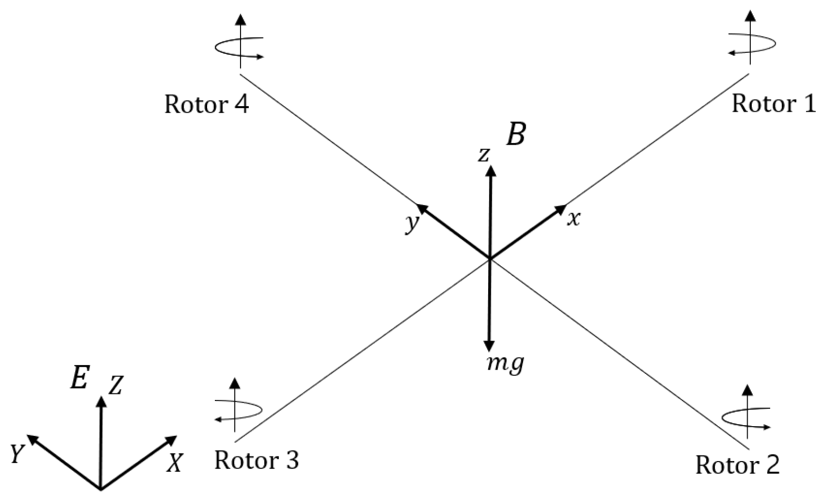
2. Problem Formulation
3. Main Result
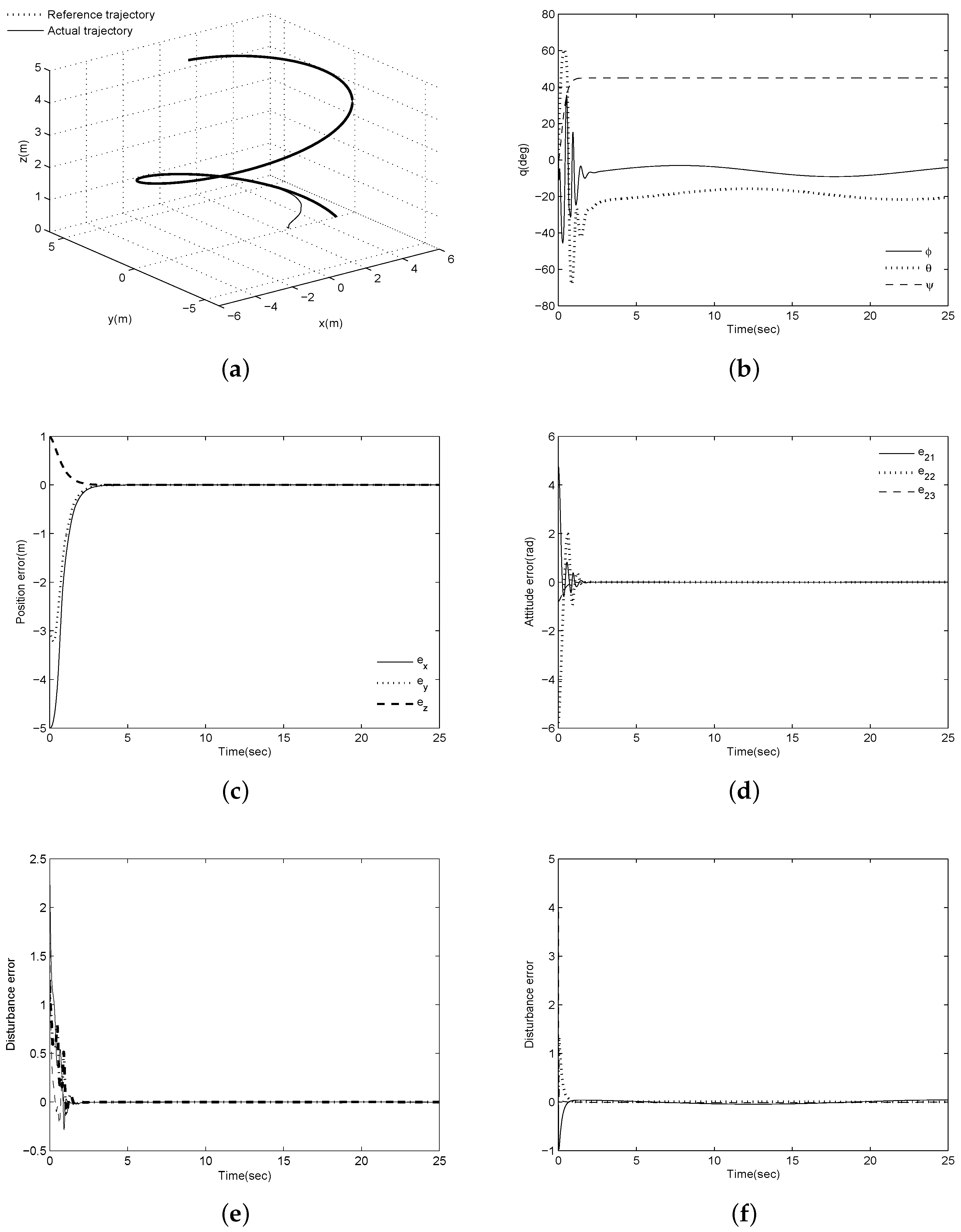
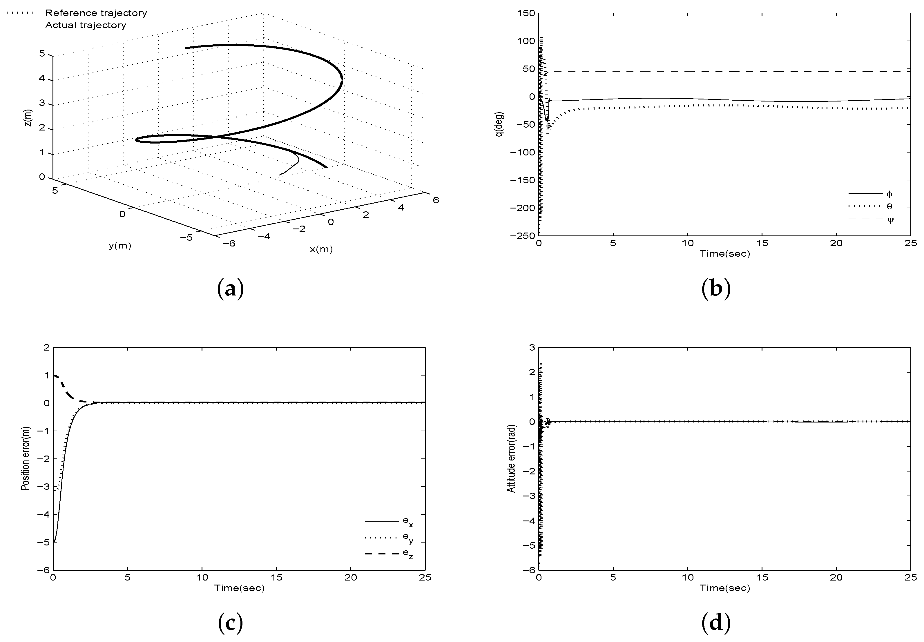
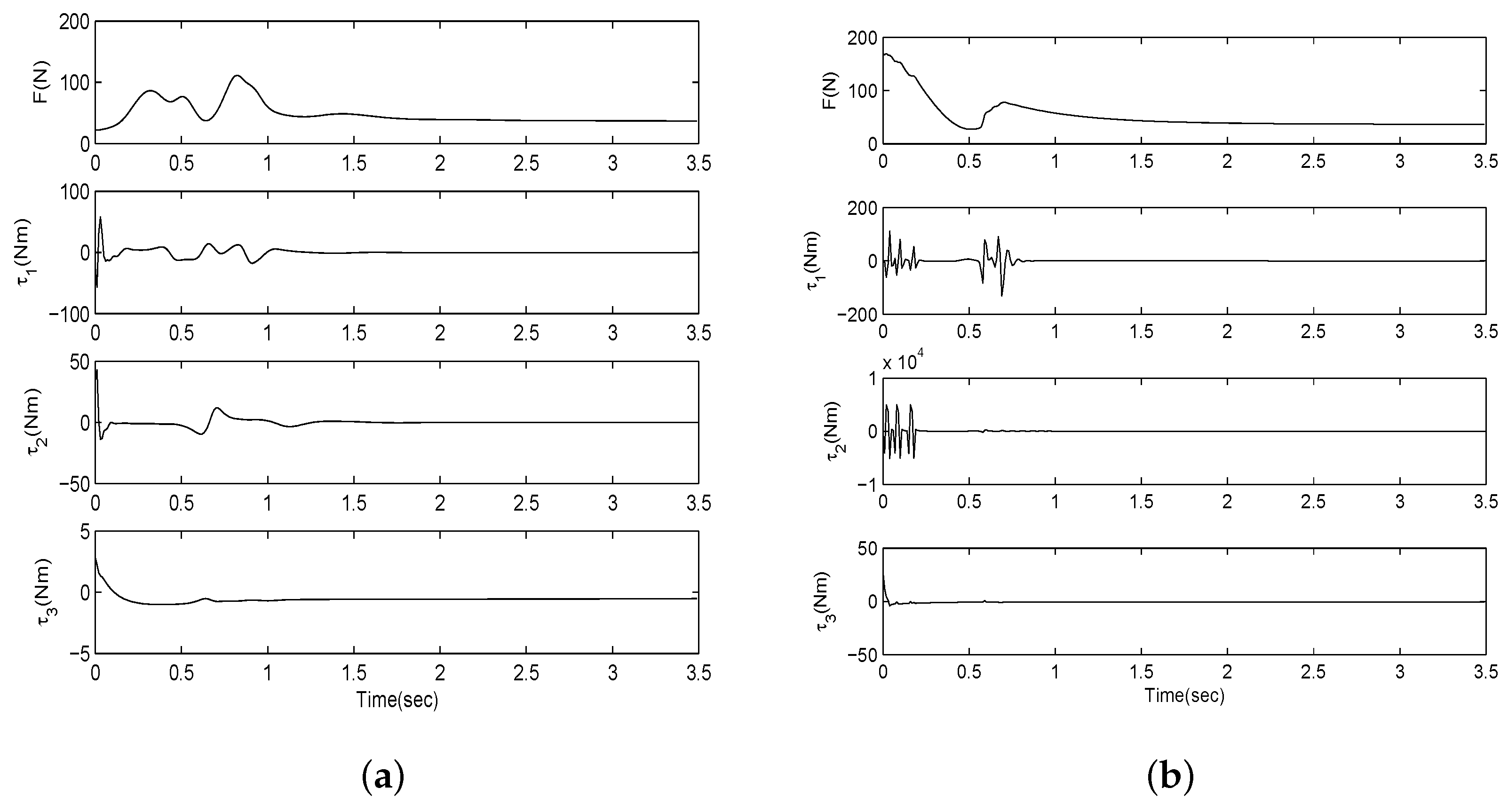
4. Simulations
5. Conclusions
Author Contributions
Funding
Conflicts of Interest
References
- Altug, E.; Ostrowski, J.P.; Mahony, R. Control of a quadrotor helicopter using visual feedback. In Proceedings of the IEEE International Conference Robotics and Automation, Washington, DC, USA, 11–15 May 2002; pp. 72–77. [Google Scholar]
- Shao, X.; Liu, N.; Liu, J.; Wang, H. Model-assisted extended state observer and dynamic surface control-based trajectory tracking for quadrotors via output-feedback mechanism. Int. J. Robust Nonlinear Control 2018, 28, 2404–2423. [Google Scholar] [CrossRef]
- Xiao, B.; Yin, S. A new disturbance attenuation control scheme for quadrotor unmanned aerial vehicles. IEEE Trans. Ind. Inform. 2017, 13, 2922–2932. [Google Scholar] [CrossRef]
- Tayebi, A.; McGilvray, S. Attitude stabilization of a VTOL quadrotor aircraft. IEEE Trans. Control Syst. Technol. 2006, 14, 562–571. [Google Scholar] [CrossRef]
- Grzonka, S.; Grisetti, G.; Burgard, W. A fully autonomous indoor quadrotor. IEEE Trans. Robot. 2012, 28, 90–100. [Google Scholar] [CrossRef]
- Mahony, R.; Kumar, V.; Corke, P. Modeling, estimation, and control of quadrotor. IEEE Trans. Robot. Autom. Mag. 2012, 19, 20–32. [Google Scholar] [CrossRef]
- Bouabdallah, S.; Noth, A.; Siegwart, R. PID vs LQ control techniques applied to an indoor micro quadrotor. In Proceedings of the IEEE/RSJ International Conference on Intelligent Robots, Sendai, Japan, 28 September–2 October 2004; pp. 2451–2456. [Google Scholar]
- Liu, H.; Lu, G.; Zhong, Y. Robust LQR attitude control of a 3-DOF laboratory helicopter for aggressive maneuvers. IEEE Trans. Ind. Electron. 2013, 60, 4627–4636. [Google Scholar] [CrossRef]
- Raffo, G.V.; Ortega, M.G.; Rubio, F.R. An underactuated H∞ control strategy for a quadrotor helicopter. In Proceedings of the European Control Conference, Budapest, Hungary, 23–26 August 2009; pp. 3845–3850. [Google Scholar]
- Gadewadikar, J.; Lewis, F.L.; Subbarao, K.; Peng, K.; Chen, B.M. H-infinity static output-feedback control for rotorcraft. J. Int. Robot. Syst. 2009, 54, 629–646. [Google Scholar] [CrossRef]
- Mellinger, D.; Kumar, V. Minimum snap trajectory generation and control for quadrotors. In Proceedings of the IEEE International Conference on Robotics Automation, Shanghai, China, 9–13 May 2011; pp. 2520–2525. [Google Scholar]
- Lee, T.; Leok, M.; McClamroch, N.H. Nonlinear robust tracking control of a quadrotor UAV on SE(3). Asian J. Control 2013, 15, 391–408. [Google Scholar] [CrossRef]
- Hua, M.D.; Hamel, T.; Morin, P.; Samson, C. A control approach for thrust-propelled underactuated vehicles and its application to VTOL drones. IEEE Trans. Autom. Control 2009, 54, 1837–1853. [Google Scholar]
- Hua, M.D.; Hamel, T.; Morin, P.; Samson, C. Introduction to feedback control of underactuated VTOL vehicles: A review of basic control design ideas and principles. IEEE Trans. Control Syst. Technol. 2013, 33, 61–75. [Google Scholar]
- Zou, Y. Nonlinear robust adaptive hierarchical sliding mode control approach for quadrotors. Int. J. Robust Nonlinear Control 2017, 27, 925–941. [Google Scholar] [CrossRef]
- Chen, F.; Lei, W.; Zhang, K.; Tao, G.; Jiang, B. A novel nonlinear resilient control for a quadrotor UAV via back-stepping control and nonlinear disturbance observer. Nonlinear Dyn. 2016, 85, 1281–1295. [Google Scholar] [CrossRef]
- Lee, C.T.; Tsai, C.C. Adaptive backstepping integral control of a small-scale helicopter for airdrop missions. Asian J. Control 2010, 12, 531–541. [Google Scholar] [CrossRef]
- Zhao, B.; Xian, B.; Zhang, Y.; Zhang, X. Nonlinear robust adaptive tracking control of a quadrotor UAV via immersion and invariance methodology. IEEE Trans. Ind. Electron. 2015, 62, 2891–2902. [Google Scholar] [CrossRef]
- Xiong, J.; Zheng, E. Position and attitude tracking control for a quadrotor. ISA Trans. 2014, 53, 725–731. [Google Scholar] [CrossRef]
- Almakhles, D.J. Robust backstepping sliding mode control for a quadrotor trajectory tracking application. IEEE Access 2020, 8, 5515–5525. [Google Scholar] [CrossRef]
- Castan˜eda, H.; Gordillo, J.L. Embedded flight control based on adaptive sliding mode strategy for a quadrotor micro air vehicle. Electronics 2019, 8, 793. [Google Scholar] [CrossRef]
- Dierks, T.; Jagannathan, S. Output feedback control of a quadrotor UAV using neural networks. IEEE Trans. Neural Netw. 2010, 21, 50–66. [Google Scholar] [CrossRef]
- Shin, J.; Kim, H.J.; Kim, Y.; Dixon, W.E. Autonomous flight of the rotorcraft-based UAV using RISE feedback and NN feedforward terms. IEEE Trans. Control Syst. Technol. 2012, 20, 1392–1399. [Google Scholar] [CrossRef]
- Hu, J.; Zhang, H. Immersion and invariance based command-filtered adaptive backstepping control of VTOL vehicles. Automatica 2013, 49, 2160–2167. [Google Scholar] [CrossRef]
- Zou, Z. Trajectory tracking control design with command-filtered compensation for a quadrotor. IET Control Theory Appl. 2010, 4, 2343–2355. [Google Scholar]
- Jiang, T.; Lin, D.; Song, T. Finite-time backstepping control for quadrotors with disturbances and input constraints. IEEE Access 2018, 6, 62037–62049. [Google Scholar] [CrossRef]
- Tian, B.; Lu, H.; Zou, Z.; Zong, Q.; Zhang, Y. Multivariable finite-time output feedback trajectory tracking control of quadrotor helicopters. Int. J. Robust Nonlinear Control 2018, 28, 281–295. [Google Scholar] [CrossRef]
- Kim, S.; Ahn, C.K.; Shi, P. Performance recovery tracking-controller for quadcopters via invariant dynamic surface approach. IEEE Trans. Ind. Inform. 2019, 15, 5235–5243. [Google Scholar] [CrossRef]
- Lee, T.; Kim, Y. Nonlinear adaptive flight control using backstepping and neural networks controller. J. Guid. Control Dyn. 2001, 24, 675–682. [Google Scholar] [CrossRef]
- Bouabdallah, S.; Siegwart, R. Backstepping and sliding-mode techniques applied to an indoor micro quadrotor. In Proceedings of the IEEE International Conference on Robotics Automatic, Barcelona, Spain, 18–22 April 2005; pp. 2247–2252. [Google Scholar]
- Do, K.K. Practical formation control of multiple underactuated ships with limited sensing ranges. Robot. Auton. Syst. 2011, 59, 457–471. [Google Scholar] [CrossRef]
- Mohammadia, A.; Tavakoli, M.; Marquez, H.J.; Hashemzadeh, F. Nonlinear disturbance observer design for robotic manipulators. Control Eng. Pract. 2013, 21, 253267. [Google Scholar] [CrossRef]
- Chen, W.H.; Ballance, D.J.; Gawthrop, P.J.; O’Reilly, J. A nonlinear disturbance observer for robotic manipulators. IEEE Trans. Ind. Electron. 2000, 47, 932–938. [Google Scholar] [CrossRef]
- Chen, M.; Shi, P.; Lim, C. Robust constrained control for MIMO nonlinear systems based on disturbance observer. IEEE Trans. Autom. Control 2015, 60, 3281–3286. [Google Scholar] [CrossRef]
- Swaroop, D.; Hedrick, J.K.; Yip, P.P.; Gerdes, J.C. Dynamic surface control for a class of nonlinear systems. IEEE Trans. Autom. Control 2000, 45, 1893–1899. [Google Scholar] [CrossRef]
- Chen, F.; Jiang, R.; Zhang, K.; Jiang, B.; Tao, G. Robust backstepping sliding mode control and observer-based fault estimation for a quadrotor UAV. IEEE Trans. Ind. Electron. 2016, 63, 5044–5056. [Google Scholar] [CrossRef]
- Pounds, P.; Mahony, R.; Corke, P. Modeling and control of a large quadrotor robot. Control Eng. Pract. 2010, 18, 691–699. [Google Scholar] [CrossRef]


© 2020 by the authors. Licensee MDPI, Basel, Switzerland. This article is an open access article distributed under the terms and conditions of the Creative Commons Attribution (CC BY) license (http://creativecommons.org/licenses/by/4.0/).
Share and Cite
Ha, S.W.; Park, B.S. Disturbance Observer-Based Control for Trajectory Tracking of a Quadrotor. Electronics 2020, 9, 1624. https://doi.org/10.3390/electronics9101624
Ha SW, Park BS. Disturbance Observer-Based Control for Trajectory Tracking of a Quadrotor. Electronics. 2020; 9(10):1624. https://doi.org/10.3390/electronics9101624
Chicago/Turabian StyleHa, Sang Wook, and Bong Seok Park. 2020. "Disturbance Observer-Based Control for Trajectory Tracking of a Quadrotor" Electronics 9, no. 10: 1624. https://doi.org/10.3390/electronics9101624
APA StyleHa, S. W., & Park, B. S. (2020). Disturbance Observer-Based Control for Trajectory Tracking of a Quadrotor. Electronics, 9(10), 1624. https://doi.org/10.3390/electronics9101624