Article

Research on the System and Control Strategy of an AC-DC Hybrid Single-Phase Electric Energy Router

School of electrical and electronic engineering, North China Electric Power University, Beijing 102206, China
*
Author to whom correspondence should be addressed.
Electronics 2019, 8(9), 970; https://doi.org/10.3390/electronics8090970
Submission received: 31 July 2019 / Revised: 24 August 2019 / Accepted: 29 August 2019 / Published: 30 August 2019
(This article belongs to the Special Issue Advanced Power Conversion Technologies)

Abstract

:
With the extensive development and use of new energy sources, it has become an urgent issue to solve the problem how to effectively use such energy sources. This paper designs a single-phase electric energy router (SPEER) whose main goal is to solve the problem of optimal operation of the home power system under a high penetration rate of new energy. First, a SPEER structure is presented which has an AC-DC hybrid form to meet the power requirements of all household electrical equipment. Compared with the existing structures, its structural design is more suitable for small-capacity systems, such as home power systems. Next, a reasonable, detailed, and feasible control scheme was designed for each part of the SPEER, so that it has the functions of plug and play, power routing, island detection, and synchronous grid connection, and a seamless coordination management scheme between subsystems was designed. Complete functions make it more intelligent in response to various conditions. Finally, the correctness of the designed SPEER and control strategy was verified by experiment.

1. Introduction

In order to solve the energy shortage problem, people turn their attention to new energy sources. Therefore, a large number of distributed renewable energy power generation devices have been incorporated into the power grid, such as wind power inverters and photovoltaic power inverters. However, these distributed power supplies have some notable features: geographical dispersion, intermittent, and random. How to effectively use such renewable energy has become a concern [1,2,3].
An electric energy router (EER) based on power electronic conversion technology emerged [4]. The EER is a kind of power equipment that combines information technology and power electronic conversion technology to realize the efficient use and transmission of distributed energy [5]. According to the power grade of the EER and its position in the distribution network [6], the EER was divided into three categories, namely, mainline EER, regional EER, and home EER. This paper focused on the research on the home EER. The EER using a high-frequency isolating transformer [7,8,9,10] can reduce the volume of the equipment and improve the efficiency of the equipment, but the high-frequency isolating transformer had a complex control and increased the cost [11]. It was not conducive to use in small-capacity systems, especially home EERs. Some studies [12,13] adopted a H-bridge cascade structure, while other studies [14,15] adopted a modular structure. They were also suitable for high-voltage and high-power occasions but not for single-phase EERs. One study [16] provided three typical structures of EER and established corresponding evaluation indexes but did not involve the specific topology. Another study [17] presented a home EER structure of an AC-DC hybrid micro-network architecture but only conducted simulation research under simple working conditions. In [18], a home energy router and energy management strategy for AC/DC hybrid sources and consumers was proposed. By using the distributed hierarchical energy management system (HEMS), energy routing could be achieved to obtain different functions, such as peak load shifting, electricity plan following, etc. However, the HEMS mentioned in the article is cumbersome and impractical. For example, it requires that “users use the human-machine interaction interface such as App. in smartphones to arrange the power consumption time and target”. This is obviously not practical, since users’ electricity use behavior is often random and uncertain. This requirement is a heavy burden on users. Another study [19] proposed a HEMS based on an energy router. By controlling the switch array, the optimal matching of the power supply and the load is realized, so that the renewable energy is used to the maximum extent. However, this method requires that household appliances are classified according to the degree of sensitivity to the power quality, divided into sensitive and non-sensitive loads, and even the same type of household appliance is different for different people, which complicates the previous planning. At the same time, this solution requires a switch array, which greatly increases the cost. Based on the functional requirements of EER, a preliminary analysis of its structural construction was provided [20,21], but it was only a theoretical analysis, and no specific control scheme and result verification was provided.
Combined with existing research, this paper proposes a small-capacity household-level electric energy router architecture. It has a rich electrical interface to meet the needs of various household AC and DC load powers and tries to fully develop new energy sources such as rooftop photovoltaics [22]. Because the entire device uses a decentralized control strategy, distributed power generation equipment and various home appliances can be operated by plug-and-play, and the control is simple and convenient. Through seamless cooperation of various parts of the electric energy router, the entire system can be in an optimal operating state. At the same time, it has an island detection function. When the power grid fails, the electric energy router can realize the automatic switching of the isolated network mode to achieve fault isolation and improve the power supply reliability of the home power supply system. When the grid returns to normal, it can perform grid-connected pre-synchronization and ultimately achieve impact-free grid-connected operation.
Compared with [12,13,14,15], the single-phase electric energy router (SPEER) proposed in this paper is more suitable for small-capacity systems such as home power systems and has little impact on the original home system structure, which does not require a large upgrade cost. Compared with [17,20,21], this paper does not only give the detailed control strategy of SPEER and the coordinated operation scheme of each part but also carries out experimental verification for theoretical analysis, so the proposed method is more practical. Compared with the complex HEMS proposed in [18,19], the energy management scheme in this paper is simple, intelligent, and easier to implement.

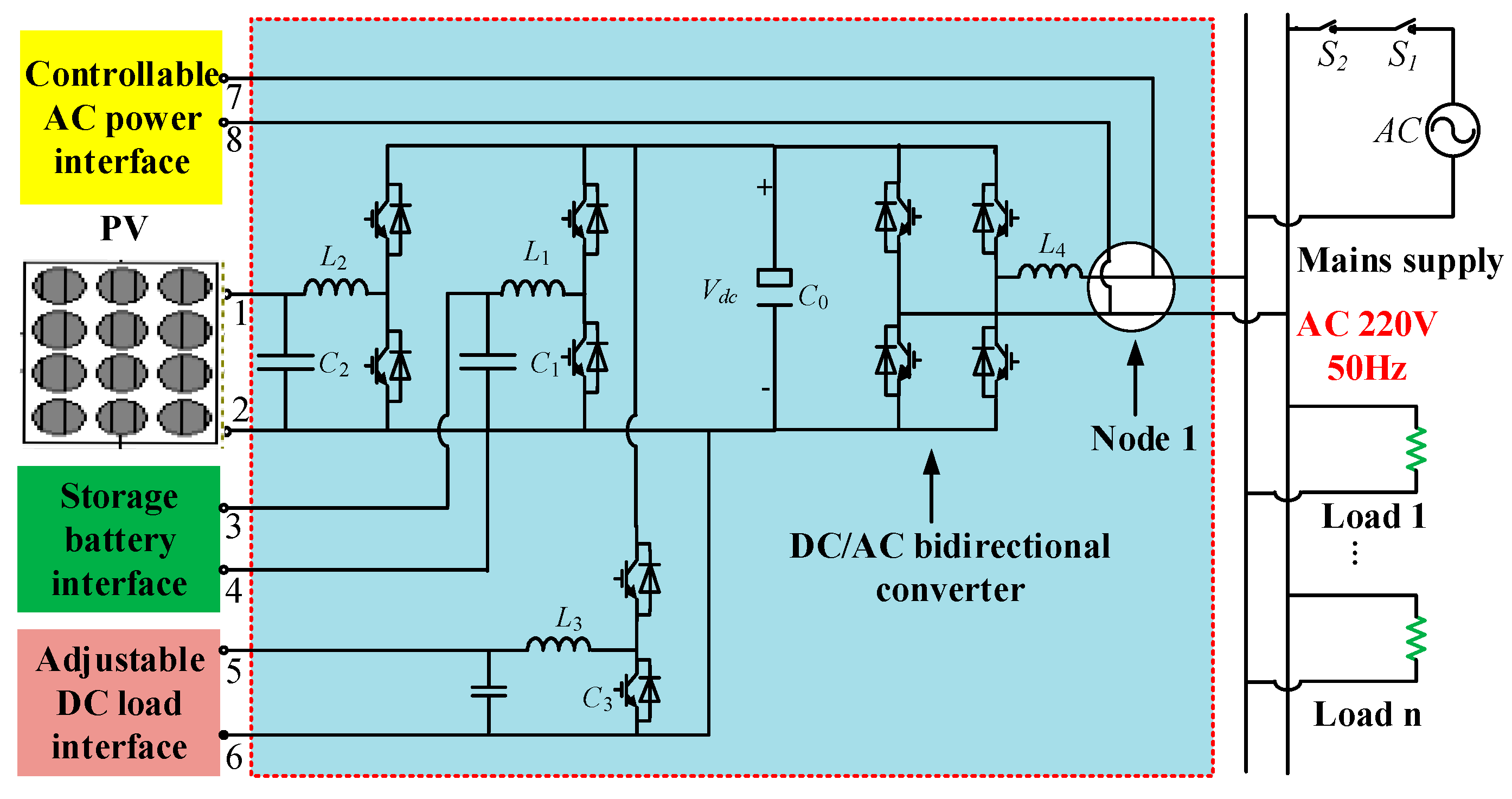
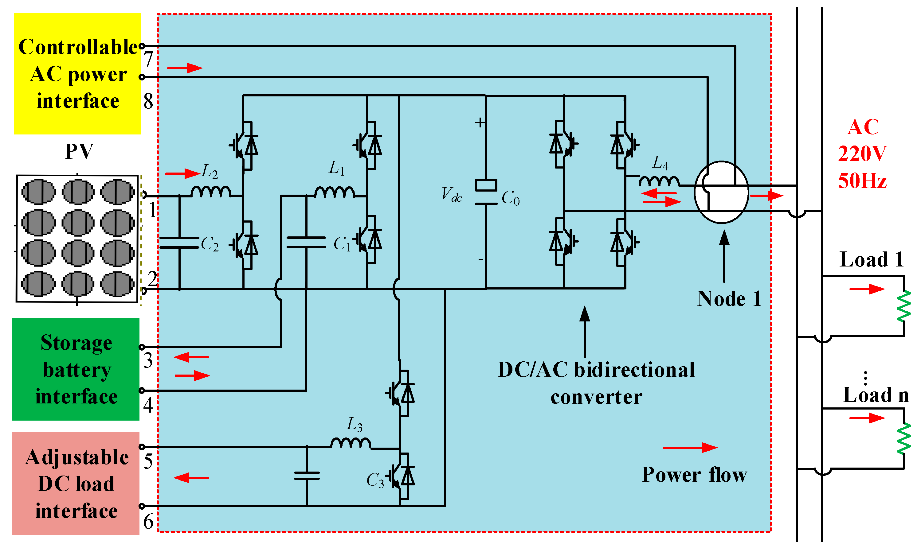
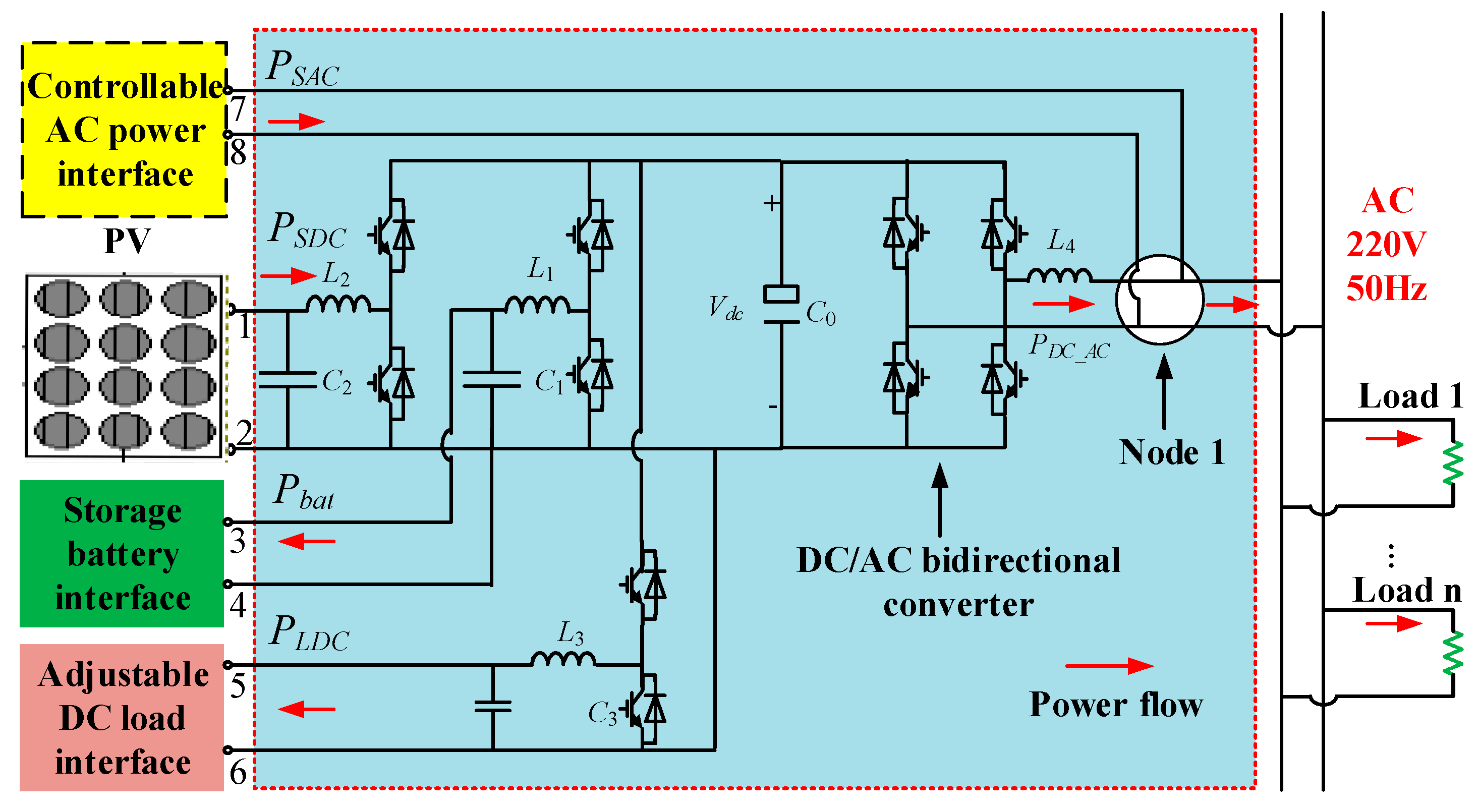
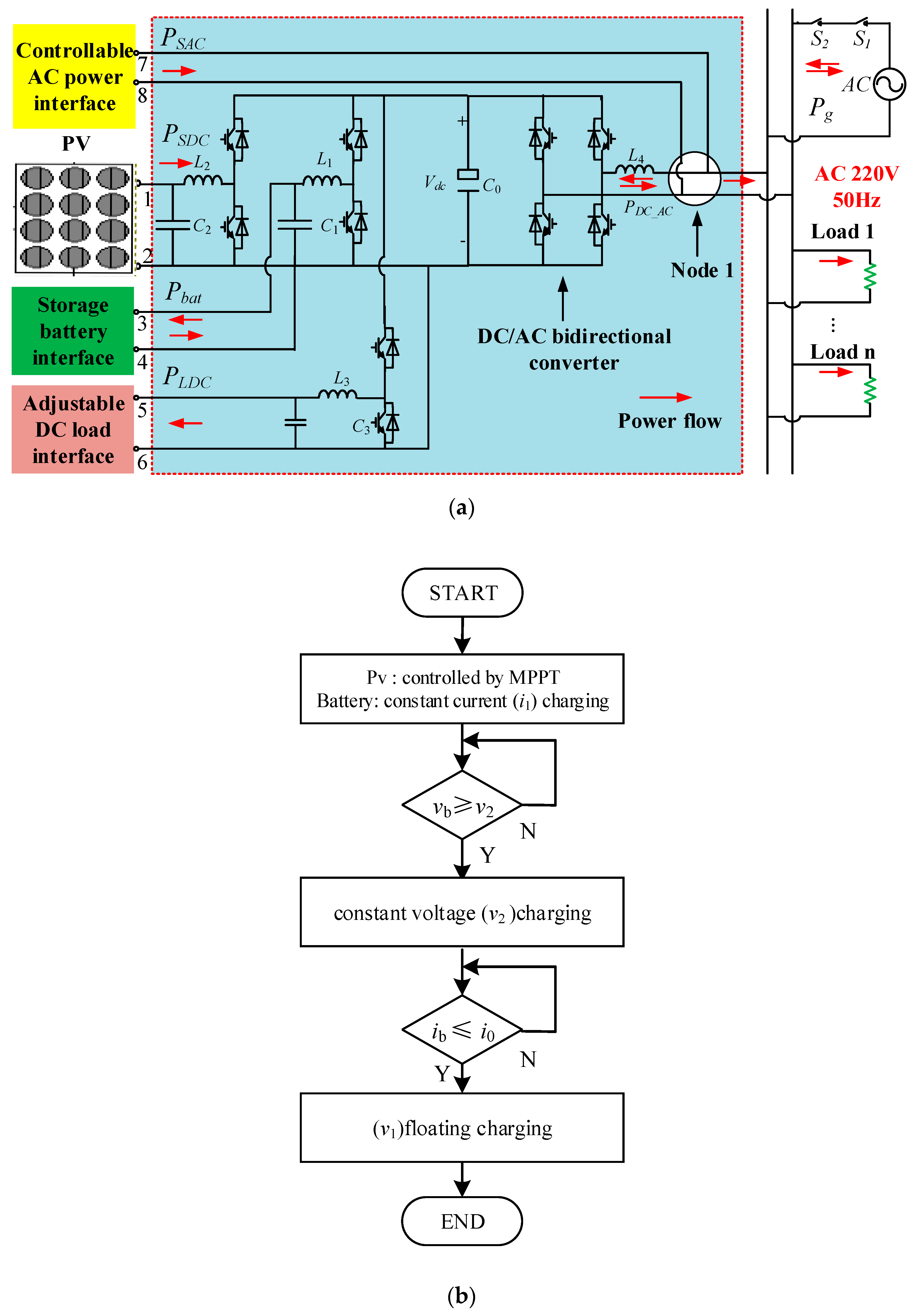
2. The Structure of A SPEER

The SPEER designed in this paper is shown in Figure 1.
Descriptions of the structural design of this SPEER:
  • Because the target population of the SPEER is the ordinary household power user and considering that most home users use single-phase AC load, the DC/AC converter in the electric energy router is designed in a single-phase form. Meanwhile, the DC/AC converter is the hub of power balance between DC and AC, so it has the ability of two-way power flow.
  • Considering some of the problems with the grid itself, such as short-circuit trips and blackouts, the power supply reliability of some important loads in ordinary households needs to be further strengthened. These loads include, but are not limited to, access control systems installed in some homes, summer refrigerators, cashier systems in small shops and restaurants, etc. Therefore, it is necessary to set a certain amount of backup power according to the actual size of the important load of the home, in order to continuously supply power for such load during the power outage.
  • At present, many households or businesses are equipped with new energy power generation equipment with a certain capacity, such as rooftop photovoltaic, and this has become a trend. Therefore, in the design of the home SPEER, it was considered to provide an access interface for such new energy equipment, which allows users to better use such energy.
  • For a small number of users who are also equipped with diesel generators and fuel cells, an AC power access interface is reserved for the electric energy router to facilitate the control and use of such power.
  • The DC load in the ordinary household is various in form, and a voltage-adjustable DC load interface is designed because of its various voltage levels and cost constraints. The user can select the appropriate voltage according to the actual usage requirements.

3. Control Strategy of SPEER

It can be seen from Figure 1 that the SPEER designed in this paper is mainly divided into two parts: AC and DC. The SPEER adopts a decentralized control strategy as a whole. The DC bus voltage is the key to the implementation of the decentralized control strategy, which is controlled by different converters in different situations. Through the seamless coordination of all parts, the single-phase electrical energy router realizes the optimal routing of electrical energy in the home power system and the efficient utilization of new energy based on meeting the requirements of the electrical equipment.

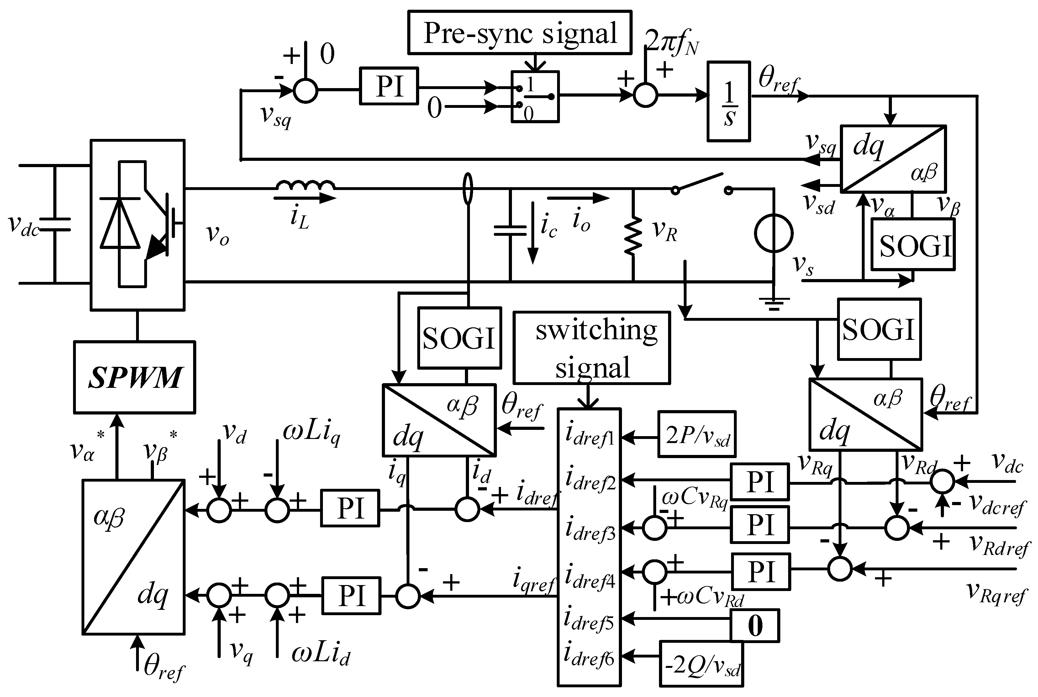
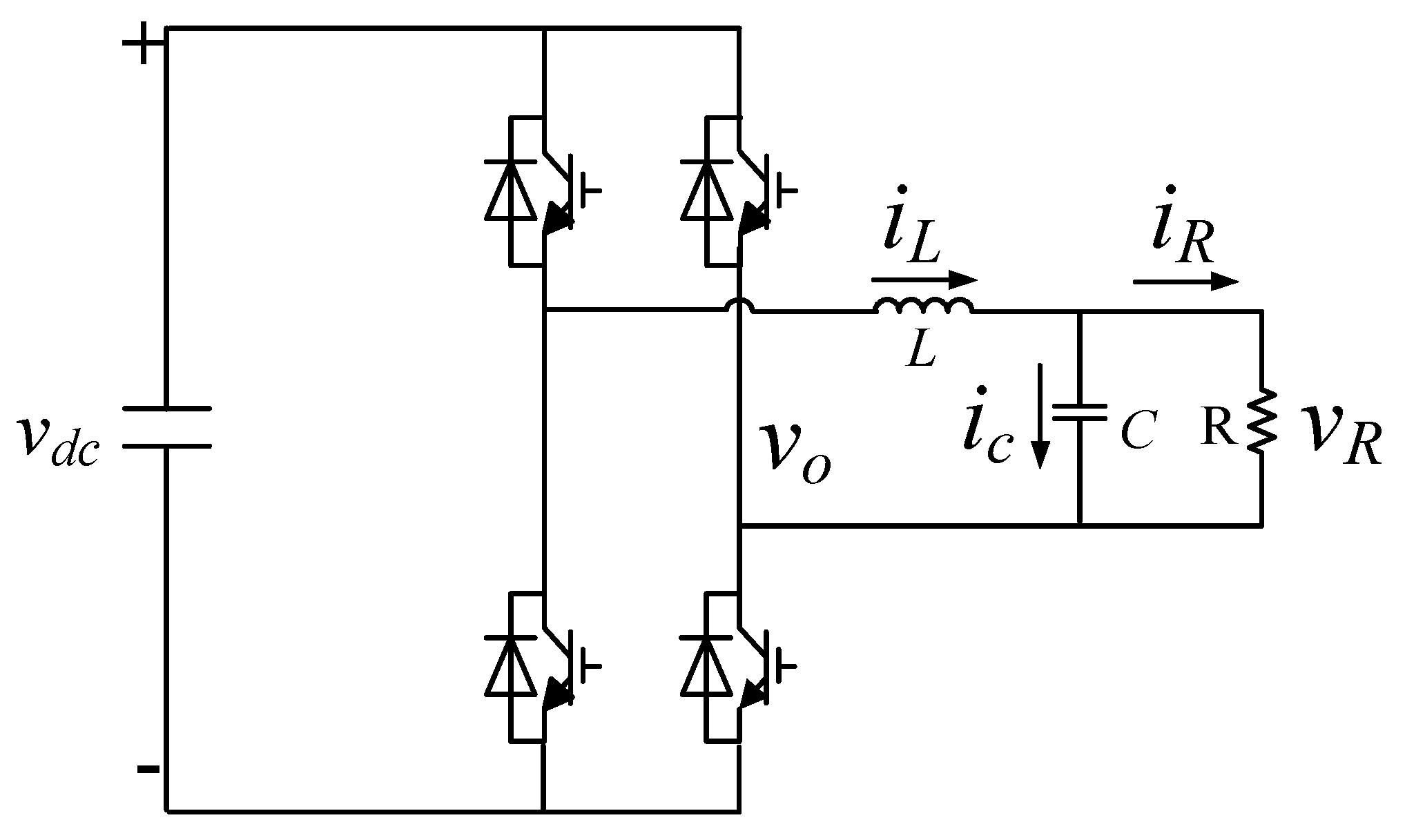
3.1. Single-Phase DC/AC Bidirectional Converter

This part is the core of the electrical energy router design. As the hub connecting the two sides of AC and DC, the DC/AC converter should not only ensure the power balance on both sides and satisfy the stability of the AC and DC bus voltage but also follow the scheduling instructions to complete the corresponding system optimization strategy when the conditions are appropriate. The DC/AC bidirectional converter must maintain the AC side voltage and frequency stability when the network is isolated.

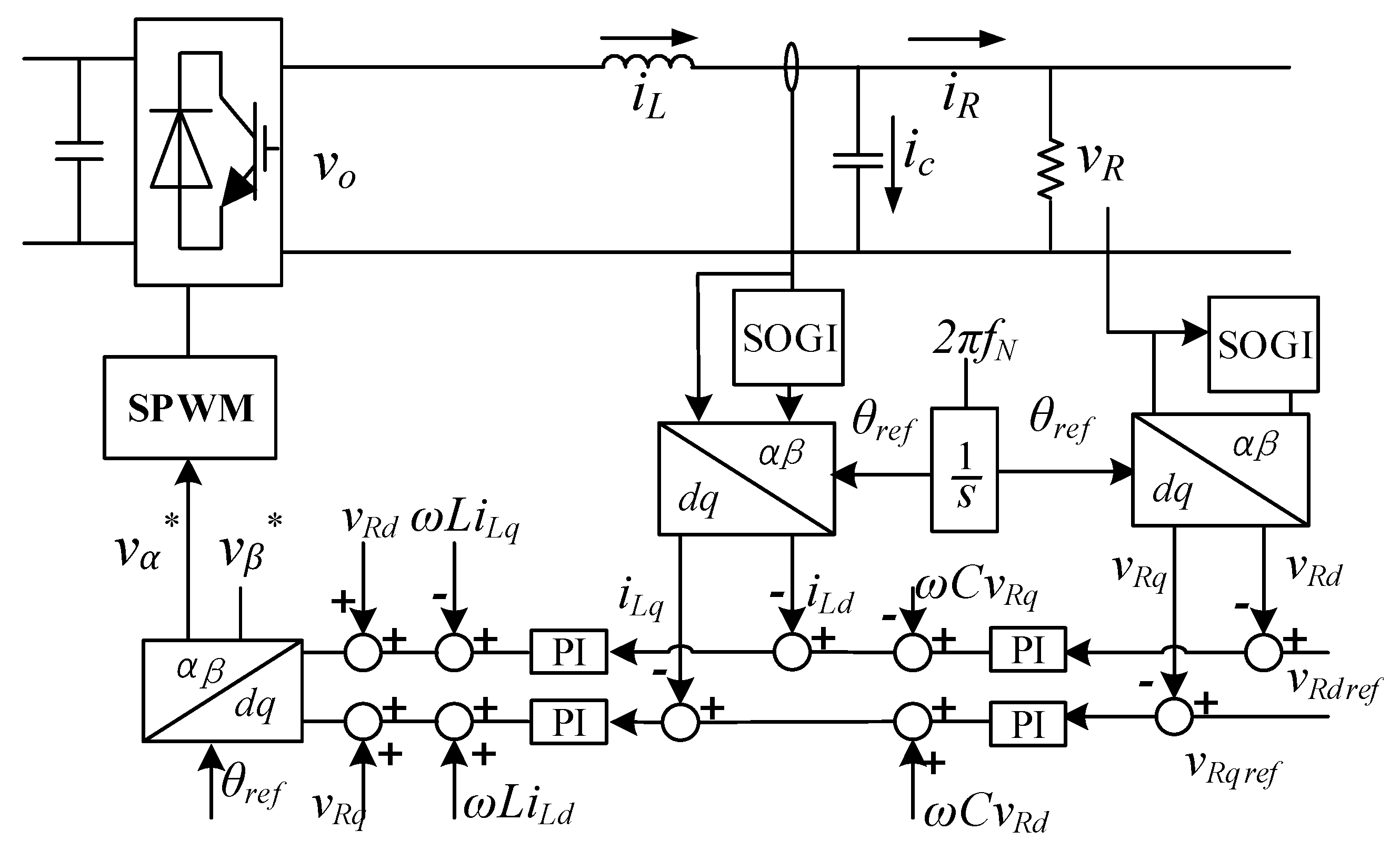
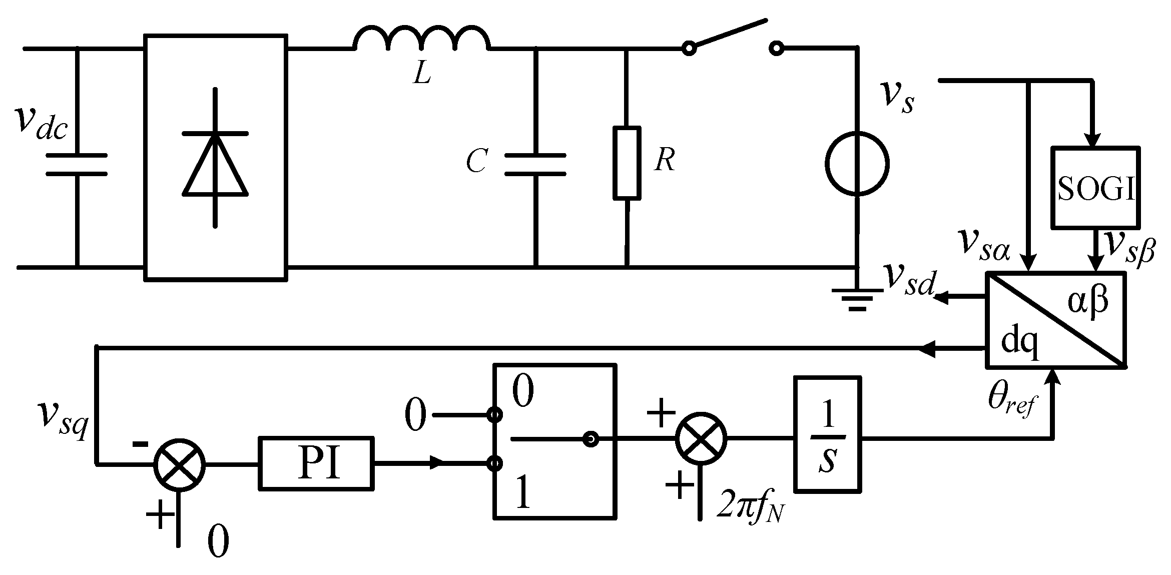
3.1.1. Single-Phase DC/AC Bidirectional Converter in Isolated Network Condition

In the isolated network, the DC bus voltage is controlled by the energy storage DC/DC bidirectional converter, and the DC/AC bidirectional converter is now operating in the inverter state, as shown in Figure 2.
When the bandwidth of the system is much less than the switching frequency, the state-space averaging method can be applied. Ignoring the internal resistance of the filter inductor, the average state-space model of the single-phase inverter can be obtained:
C d v R d t = i L i R L d i L d t = v o v R
Since the proportion integration (PI) control in the static coordinate system cannot realize the zero-error tracking of sinusoidal quantity, it is also difficult to realize the independent control of active power and reactive power. Therefore, by using the method of rotation coordinate transformation, the amount of alternating change becomes a constant amount of DC. In general, PI control can achieve zero-difference tracking and facilitate the decoupling control of active power and reactive power [23].
However, for a single-phase DC/AC converter, at least one additional degree of freedom is required to perform the coordinate transformation. In this paper, a quadrature signal generator based on a second-order generalized integrator (SOGI) is used to obtain a virtual quantity orthogonal to the actual single-phase sinusoidal AC quantity [24].
After the virtual quantity orthogonal to the actual quantity is obtained, Park transformation is carried out according to Equation (1):
d d t [ v R α v R β ] = [ 1 C 1 C 0 0 0 0 1 C 1 C ] [ i L α i R α i L β i R β ]
d d t [ i L α i L β ] = [ 1 L 1 L 0 0 0 0 1 L 1 L ] [ v o α v R α v o β v R β ]
Therefore, the equation of state in the rotation coordinate system can be obtained:
d d t [ v R d v R q ] = [ 1 R C ω 1 C 0 ω 1 R C 0 1 C ] [ v R d v R q i L d i L q ]
d d t [ i L d i L q ] = [ 1 L 0 0 ω 0 1 L ω 0 ] [ v R d v R q i L d i L q ] + [ v o d v o q ]
Referring to the decoupling method of a three-phase inverter, the feedforward decoupling control strategy is adopted to realize independent control of the d and q axis variables.
Current inner loop:
{ v d = k i p ( i L d r e f i L d ) ω L i L q + v R d v q = k i p ( i L q r e f i L q ) + ω L i L d + v R q
Voltage outer ring:
{ i L d r e f = ( k v p + k v i s ) ( v d r e f v R d ) ω C v R q i L q r e f = ( k v p + k v i s ) ( v q r e f v R q ) + ω C v R d
After feedforward decoupling, there are:
{ C d v R d d t = ( k v p + k v i s ) ( v d r e f v R d ) C d v R q d t = ( k v p + k v i s ) ( v q r e f v R q ) L d i L d d t = k i p ( i L d r e f i L d ) L d i L q d t = k i p ( i L q r e f i L q )
The final V/f control block diagram of single-phase inverter is shown in Figure 3.

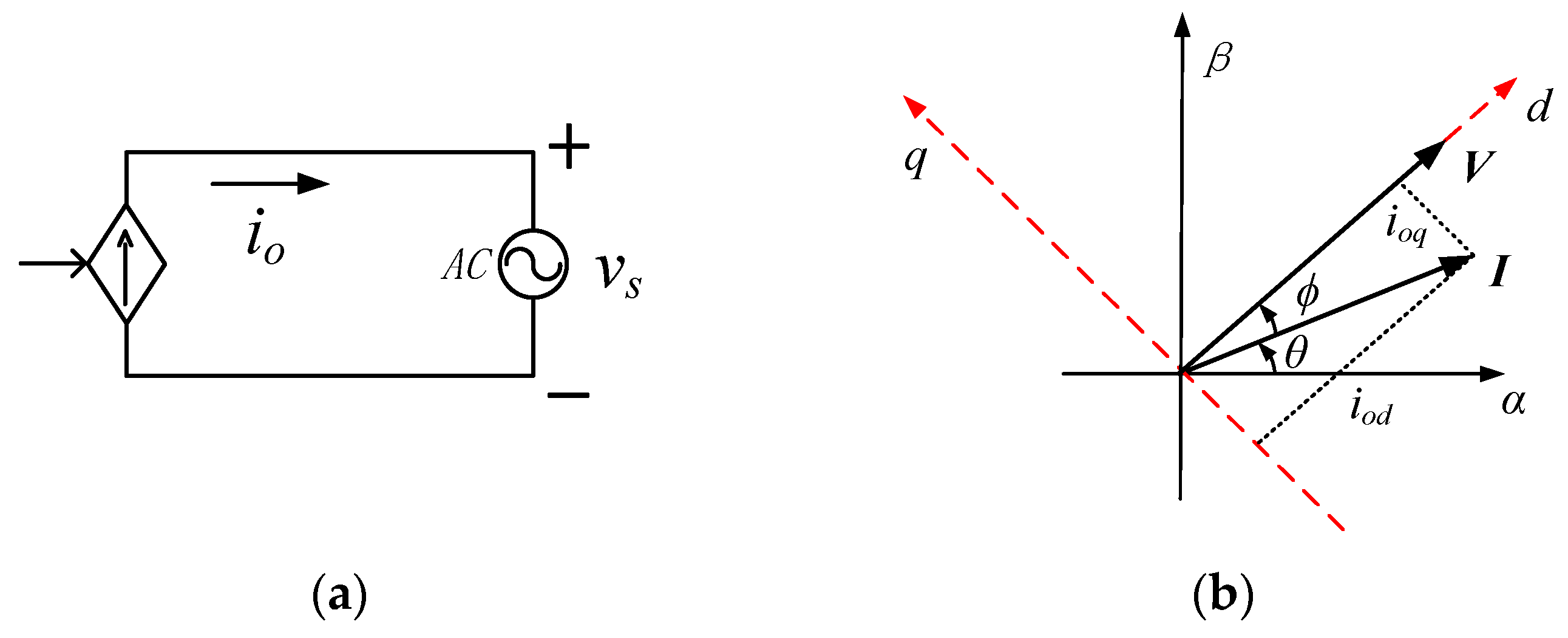
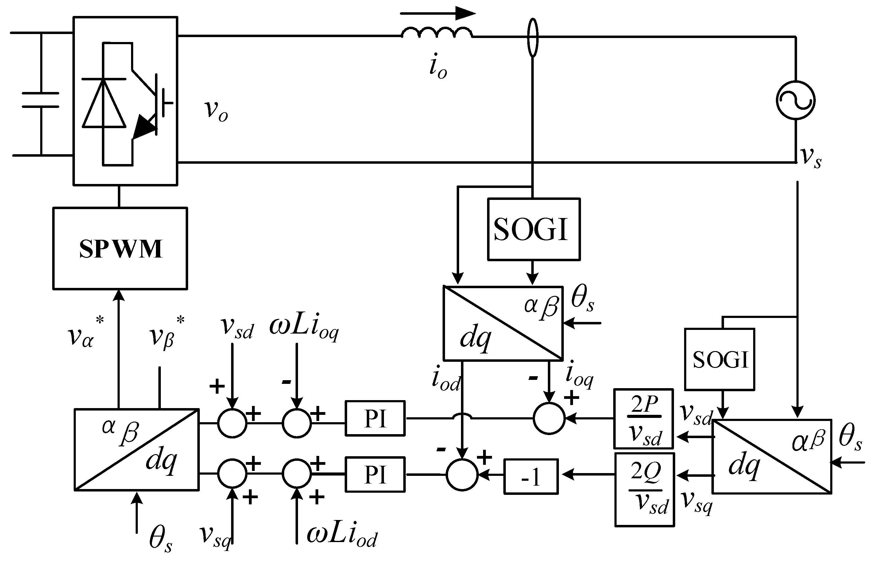
3.1.2. Single-Phase DC/AC Bidirectional Converter under Grid-Connected Operation Condition

In the case of grid connection, an active power and reactive power (PQ) control strategy is adopted for single-phase DC/AC bi-directional converters. The PQ control strategy is divided into two forms:

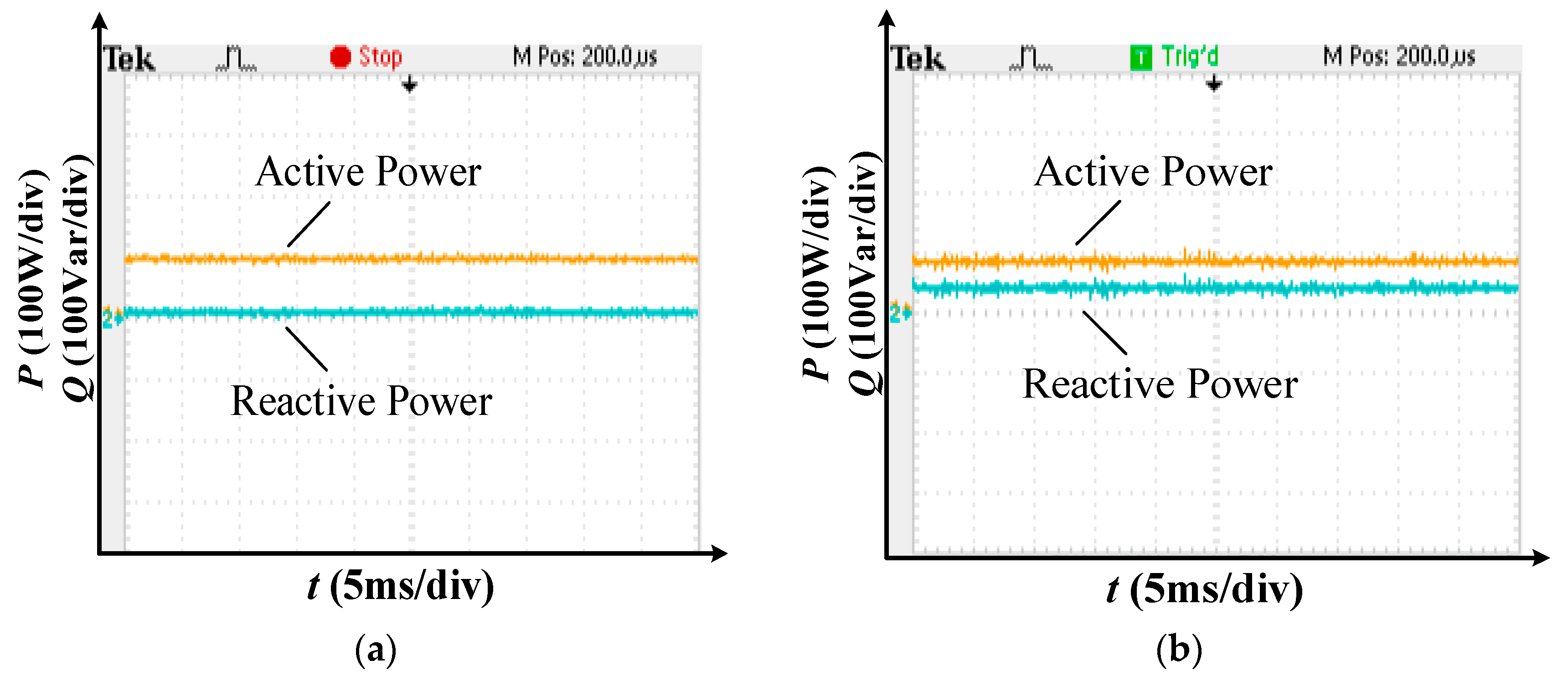
PQ Control Strategy with Power as Outer Loop

Given the power P and Q are the outer loop and the current is the inner loop, generally, when this control method is adopted, Q is 0. At this point, the converter can be equivalent to a controlled current source, as shown in Figure 4a. After the single-phase DC/AC bidirectional converter is connected to the grid, the port voltage is forced to be the grid voltage, and the current is given by the control system. Without loss of generality, suppose:
{ v s = V m cos ( ω t + φ ) i o = I m cos ( ω t )
That is, the port voltage of the single-phase inverter leads the output current by an angle φ. At this time, the inverter outputs active and reactive power:
{ P = v s i o cos φ Q = v s i o sin φ
The corresponding orthogonal quantities of voltage Vs and current Io are virtualized, and then the rotation vector is synthesized, as shown in Figure 4b. In relation to Equation (10), there is: ϕ = ϕ. The d axis of the rotation coordinate system is positioned on the grid voltage vector V.
According to instantaneous reactive power theory [25], Equation (11) can be written:
{ p = v s d i o d = V m i o d q = v s d i o q = V m i o q
It can be seen from Figure 4b that
{ i o d = I m cos φ i o q = I m sin φ .
From Equations (10)–(12), we can get:
{ i o d = 2 P V m = 2 P v s d i o q = 2 Q V m = 2 Q v s d
Equation (13) gives the relationship between the output active power and reactive power of the single-phase DC/AC bi-directional converter and the current of axis d and axis q, respectively. As long as the current of the d axis and q axis is decoupled, according to Equation (13), the active power output can be precisely controlled by controlling the current of the d axis, and the reactive power output can be precisely controlled by controlling the current of the q axis. The control strategy block diagram is shown in Figure 5.

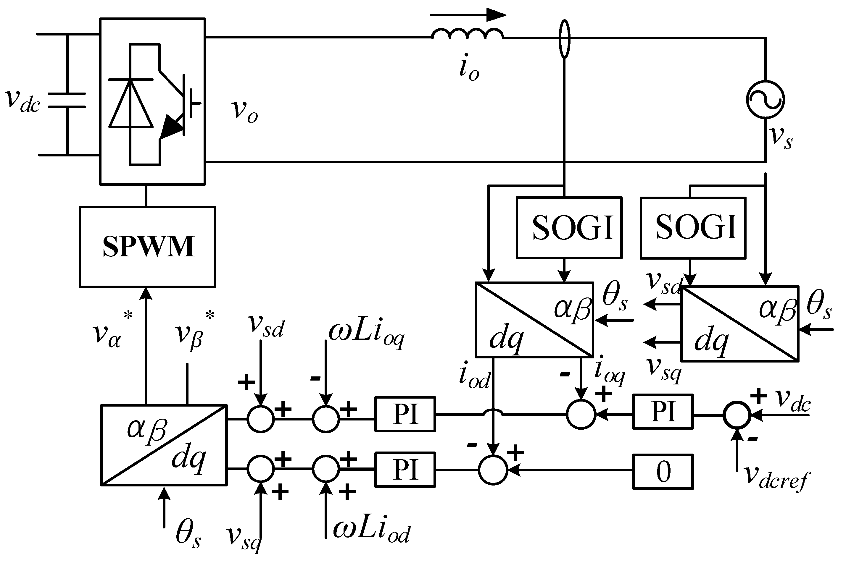
PQ Control Strategy with DC Voltage as Outer Loop

This control strategy takes DC voltage as outer loop and current as inner loop, and controls the power flowing into (or out of) the converter as a unity power factor [26]. It is similar to PQ control strategy with the power as outer loop described above, except that the outer loop becomes the DC bus voltage. The control strategy block diagram is shown in Figure 6.

3.1.3. Overall Control Strategy for the Single-Phase DC/AC Bidirectional Converter.

The single-phase DC/AC bidirectional converter needs to switch between different control strategies according to different operating conditions of the SPEER or the optimization instruction of the upper-layer control system. Only a few control strategies of single-phase DC/AC bidirectional converters are studied here, and the switching logic between various control strategies is given below. The overall control strategy block diagram of the single-phase DC/AC bidirectional converter is shown in Figure 7.

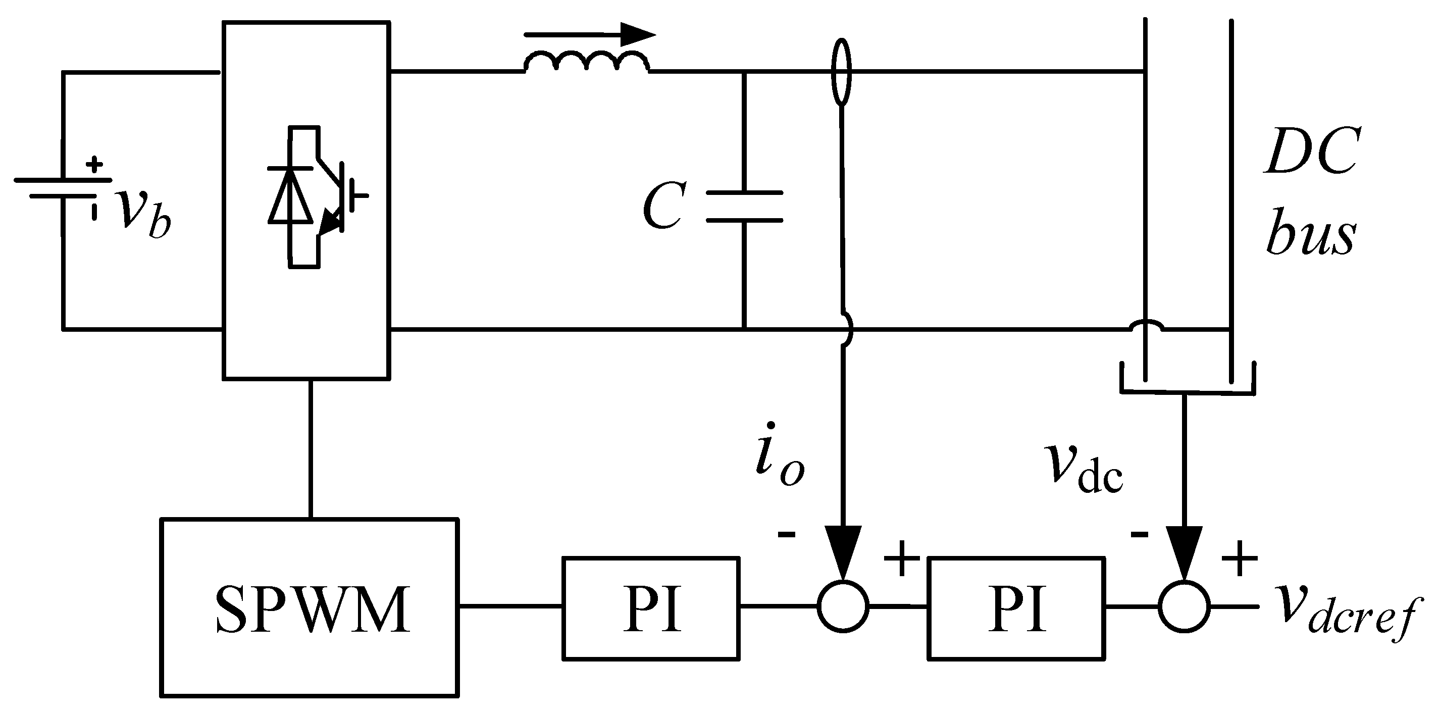
3.2. DC/DC Converter

As shown in Figure 1, there are two main types of DC side DC/DC converters: unidirectional and bidirectional converters. The unidirectional DC/DC converter is used as the photovoltaic power generation network interface, and the maximum power point tracking (MPPT) control strategy is generally used to achieve the maximum use of renewable energy. However, when the light is sufficient, so that the photovoltaic power generation is greater than the overall demand of the system, constant voltage control is required for the stable operation of the system [27].
The bidirectional DC/DC converter is used for energy storage access. The design of the energy storage uses a valve-regulated lead-acid battery. Due to different system states and different operating modes, the control of the energy storage battery will change accordingly. The following is introduced separately.

3.2.1. Energy Storage Battery Control DC Bus Voltage

The following situations require energy storage to control DC bus voltage stability:
  • When the grid fails, the SPEER is in an isolated state. Single-phase DC/AC bidirectional converters need to operate in an inverting state to support the voltage and frequency of the AC bus. The DC link voltage must now be stabilized by the battery control to ensure proper operation of the photovoltaic and single-phase DC/AC bidirectional converters.
  • When the grid is normal, the SPEER is connected to the grid. If the bidirectional DC/AC converter at this time uses the power outer loop PQ control strategy due to the instructions given by the upper system, then the DC bus voltage must also be controlled by the energy storage.
When the DC bus voltage is controlled by the energy storage, the control strategy adopts the double loop control, that is, a DC bus voltage outer loop and output current inner loop. The control block diagram is shown in Figure 8.

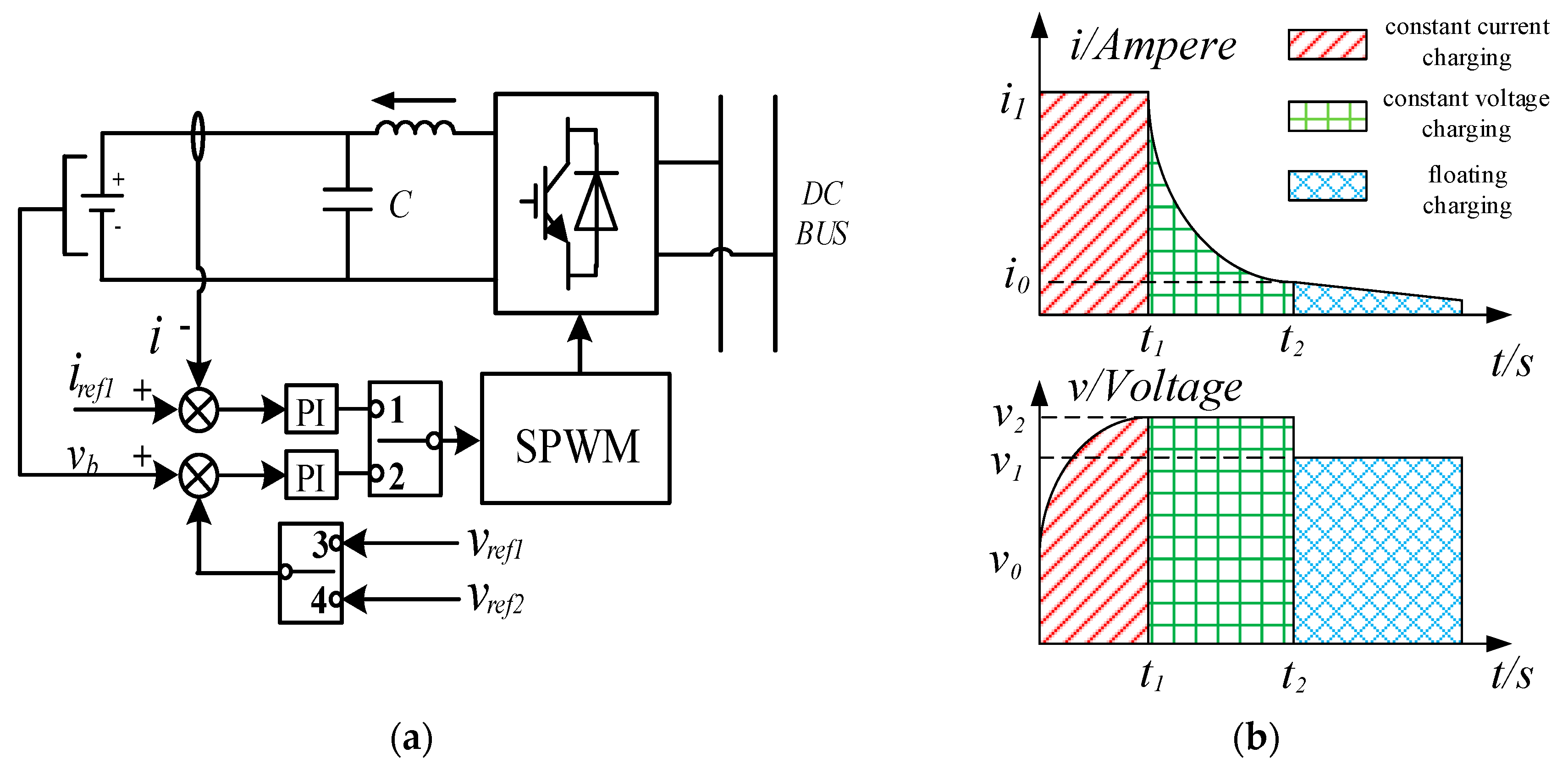
3.2.2. Energy Storage Battery Charging Strategy

When the grid is normal, the energy storage battery needs to be charged while the power is lower than the lower limit threshold, and photovoltaic (PV) still uses MPPT control to maximize the use of new energy. At this time, the DC bus voltage must be controlled only by the bidirectional DC/AC converter.
The battery charge management adopts a typical three-stage type, namely constant current charging, constant voltage charging, and floating charging [28]. The battery control strategy is shown in Figure 9a, where i 1 * , v 1 , v 2 are the current and voltage command values for constant current charging, float charging, and constant voltage charging, respectively. Considering the effect of temperature, the voltage command also needs to add a temperature compensation coefficient, that is, the voltage command changes with temperature. The threshold distribution of the energy storage battery charging control strategy is shown in Figure 9b.

3.3. Pre-Synchronization of SPEER from Isolated Networks to Grid-Connected Operation

When a SPEER needs to be connected to the grid, there may be a phase difference between the output voltage of the single-phase DC/AC bidirectional converter and the grid voltage. The most serious case is 180°, and the two voltage sources are connected in series. This is an actual short circuit, which is not allowed. Therefore, when a SPEER is connected to the network, the voltage phase pre-synchronization needs to be performed first.
In Section 3.1, a mathematical model of the single-phase DC/AC bidirectional converter in the rotating coordinate system was established, so that the SPEER grid-connected pre-synchronization can also be as convenient as a three-phase system. The typical phase control method is shown in Figure 10 [23,29].

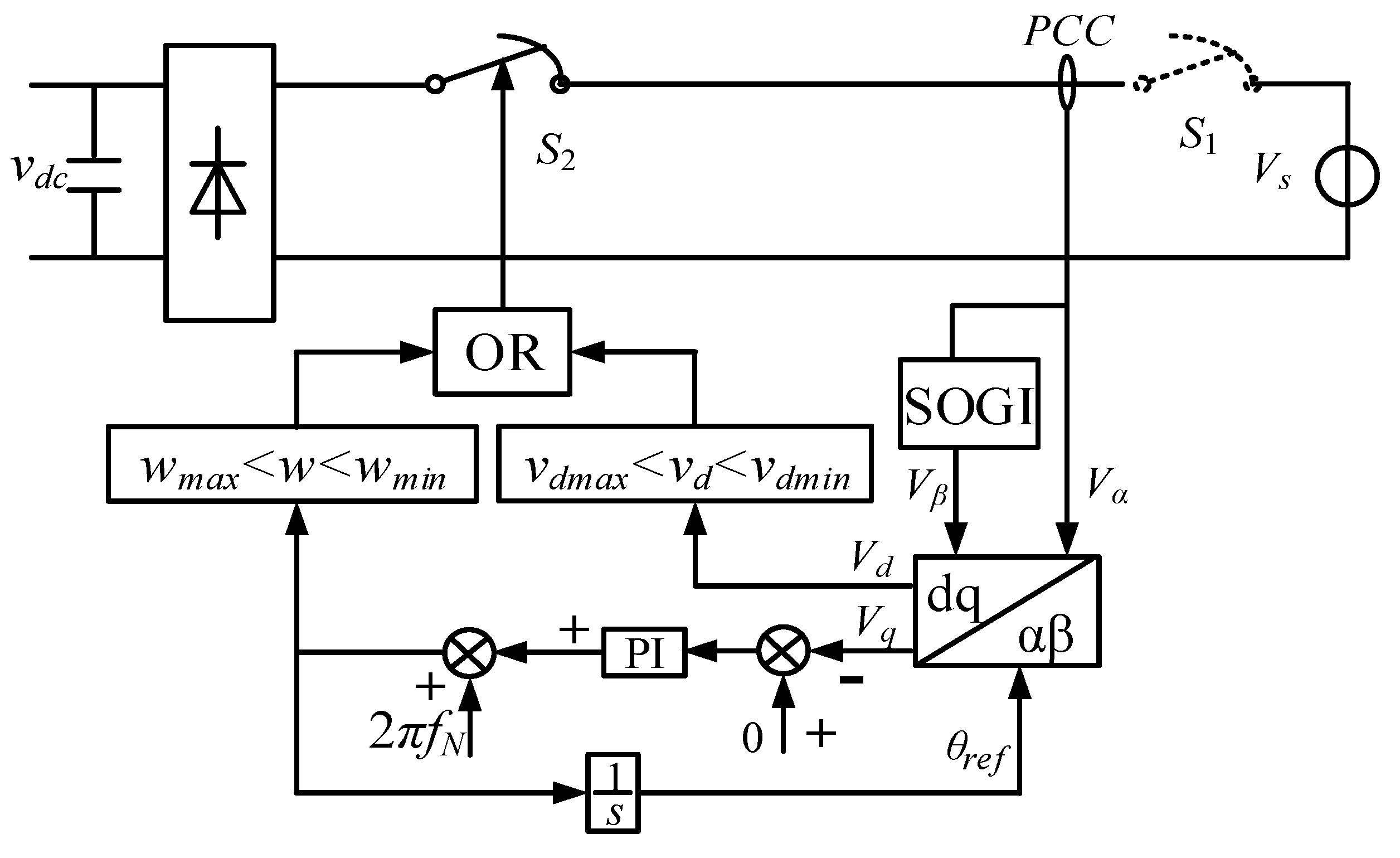
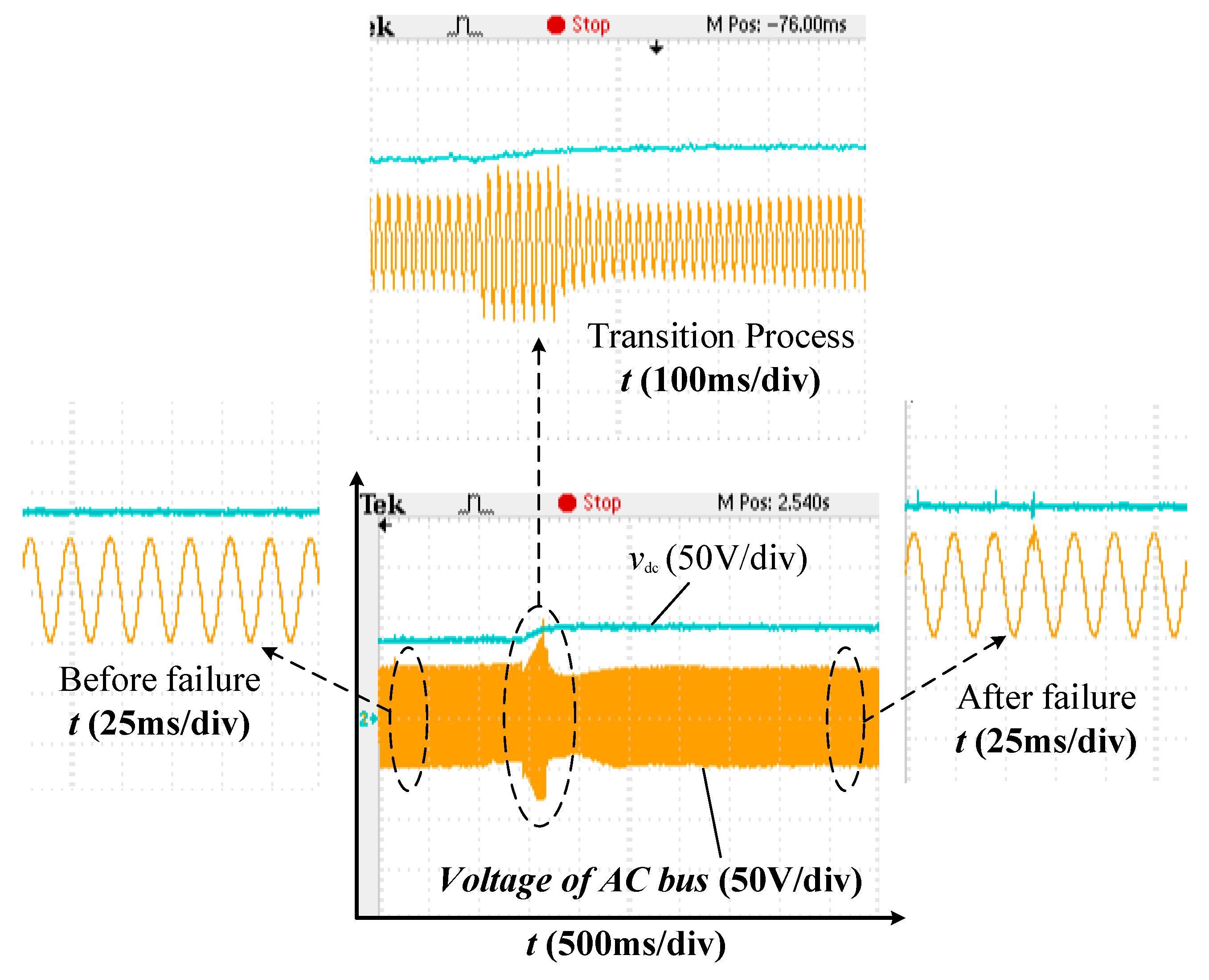
3.4. Island Detection and Off-Grid Switching Strategy

The SPEER designed in this paper, as a device that can be connected to the grid, must have the capability of island detection and off-grid switching. As shown in Figure 11, when the grid fails, S1 is disconnected. After the SPEER detects that the voltage or frequency offset of the point of common coupling (PCC) exceeds the normal range, the controller issues an off-grid signal to disconnect the contactor S2, and the operation of the SPEER changes from the grid-connected mode to the isolated mode.

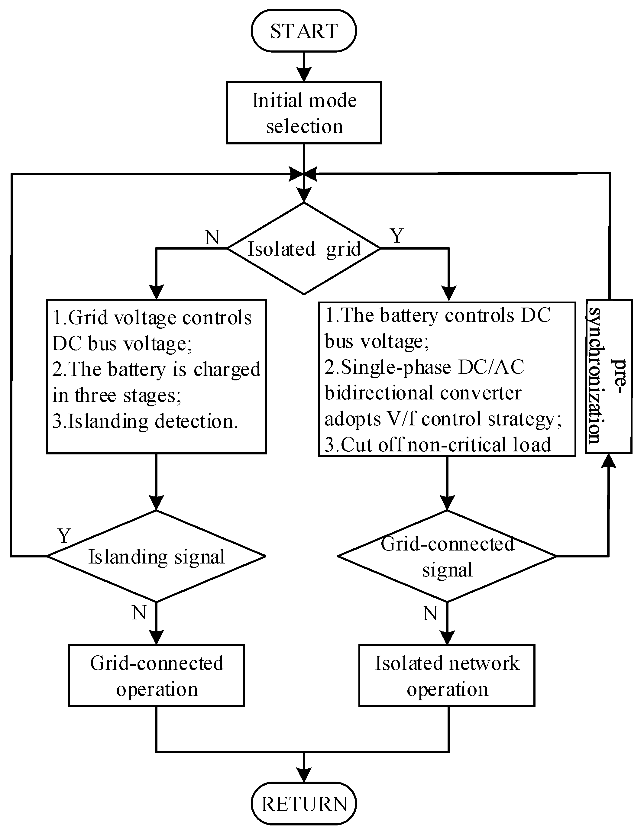
3.5. Operating Condition Analysis and Overall Control Strategy of SPEER

After completing the independent functions of each sub-module of the SPEER, it is necessary to design an overall control strategy to make the various parts become a seamless whole and complete various power routing tasks.

3.5.1. SPEER Startup

The startup of a SPEER is divided into two modes: isolated network startup and grid-connected startup.
When the power grid is normal, the SPEER can be started grid-connected. The starting sequence is as follows: first, the single-phase DC/AC bi-directional converter runs to establish a stable DC bus voltage; then the battery is charged according to the three-stage charging strategy; finally, the load, photovoltaic power, and AC controllable power supply are connected to the SPEER.
Isolated network start: first, the battery control DC bus voltage establishes a stable DC voltage; next, the DC/AC bi-directional converter operates in the inverter state to establish the AC bus voltage and frequency. Then, according to the actual situation, it chooses to connect to the grid or continue to run the isolated network; finally, the load, photovoltaic power, and AC controllable power supply are connected to the SPEER.
After starting, the SPEER can run according to the corresponding control strategy according to the actual situation.

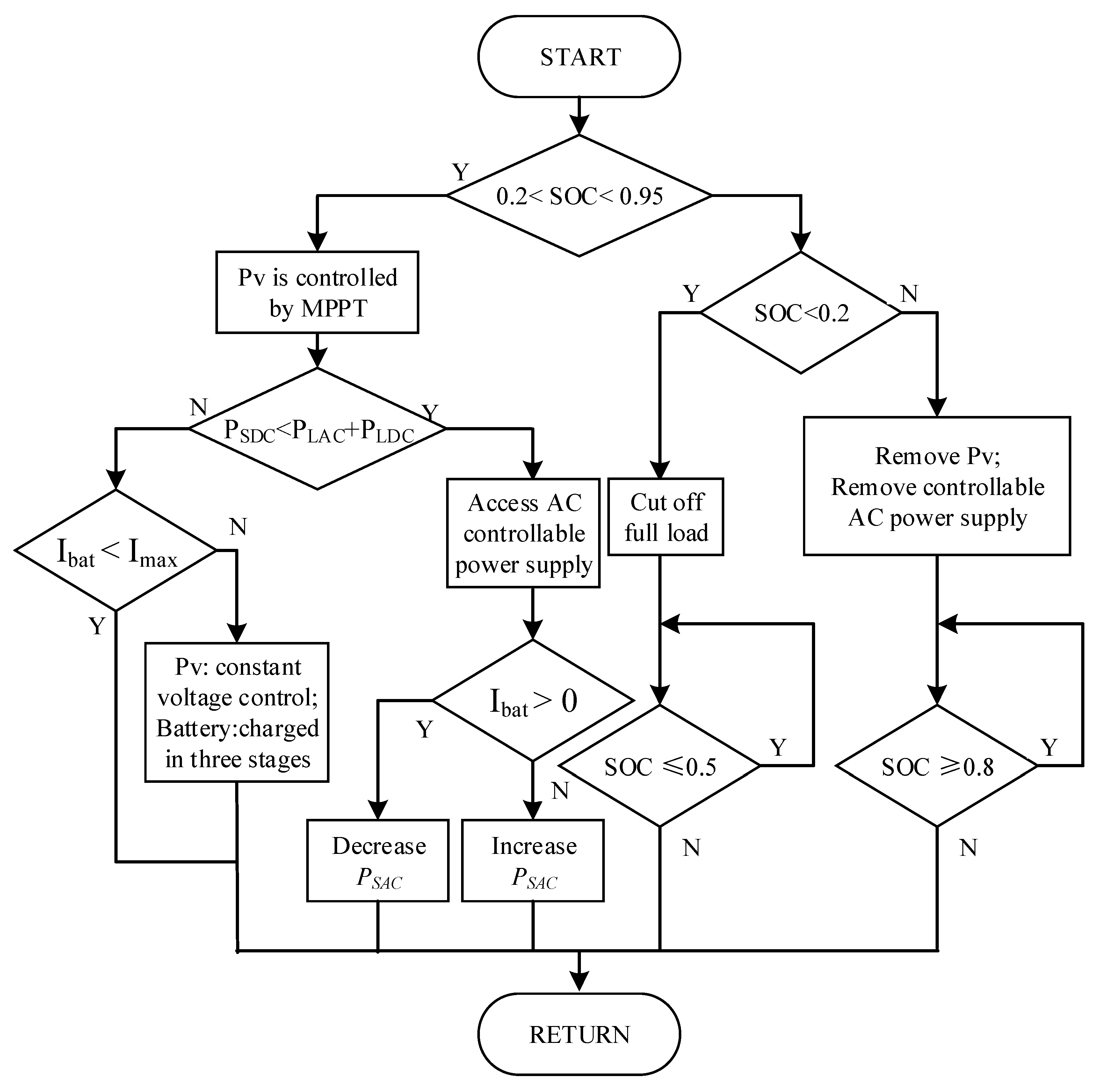
3.5.2. Control Strategy under Isolated Network Operation

In this case, the grid side circuit breaker S1 is turned off, and Pg = 0. The single-phase DC/AC bidirectional converter uses a V/f control strategy to provide voltage and frequency support to the AC bus in isolated network conditions. Small diesel generators, fuel cells, etc., are connected to the controllable AC power interface, the power input to the interface is the unity power factor, and the size is PSAC. The DC side power of the single-phase DC/AC bidirectional converter is balanced by the photovoltaic power PSDC, DC load PLDC, and battery charge and discharge power Pbat.
Set the total AC load to be PLAC = PL1 + ··· + PLn; the battery power Pbat is positive for discharge and negative for charging; the power of the single-phase DC/AC bidirectional converter PDC_AC: the direction into the AC bus is positive, and the direction into the DC bus is negative. The following is a specific analysis for different working conditions.
• PSDCPLAC + PLDC
In the case of an isolated network, the converter’s own power loss and line loss are ignored, and the total power generated by the DC power supply (photovoltaic) is less than the sum of the AC and DC loads, resulting in a power difference. At this point, if the AC power interface is not connected to the controllable power supply, the power difference mentioned above will be compensated by the energy storage battery. If the AC power interface is connected to the controllable power supply and generates power, the output power of the energy storage battery will decrease. When the controllable power is large, the energy storage battery can be charged. Considering the economy and power supply reliability comprehensively, the power sum of AC-DC power supply is equal to the sum of AC-DC load, that is, the battery does not need to send power or charge. In this case, the power flow of the SPEER is as shown in Figure 12.
• PSDC > PLAC + PLDC
In this case, the total power generated by the DC power supply is greater than the sum of the AC and DC loads, and the total power of the system is in surplus. The battery can absorb excess power without being fully charged. At this time, the DC power supply has fully met the needs of the system, so additional access to other AC power supply is not required. If the illumination improves step by step, and the emitting power increases further, the battery charging current reaches the upper limit. The photovoltaic must transform the control strategy from the maximum power tracking control to the constant voltage control to ensure the system stability, and the battery adopts three-stage charging, that is, some new energy should be abandoned. In this case, the power flow of SPEER is shown in Figure 13.
The above conditions are all carried out within the allowable working range of the battery. If the battery capacity exceeds the upper and lower thresholds, the power supply must be cut, or the load must be cut, to ensure that the battery capacity is within the allowable range. The control flow of the SPEER under the isolated network is shown in Figure 14.

3.5.3. Control Strategy under Grid-Connected Operation.

When the single-phase electrical energy router is connected to the grid, considering that it is mainly used in the household power system with a small capacity and limited by the cost, volume, and other conditions, the energy storage battery equipped with it generally has a small capacity. Therefore, the primary goal of grid-connected operation of SPEER is to ensure the reliability of important load power supply by using the energy storage battery as backup power.
In this case, the DC bus voltage is controlled and stabilized by single-phase DC/AC bi-directional converters, while the AC bus voltage and frequency are maintained by the power grid. The energy storage battery can be charged and discharged as required. The whole system meets the following requirements:
P g = P S D C + P S A C + P b a t ( P L D C + P L A C )
Pg is positive to indicate that the SPEER outputs power to the grid, and vice versa, as shown in Figure 15a.
The main advantages of this control strategy are: the battery is only put into operation when the power grid fails, usually as a backup power in the state of floating charge, which is conducive to the battery life extension; in most cases, photovoltaic power generation adopts an MPPT control strategy and uses new energy to a large extent. Disadvantages: the power into the network may fluctuate greatly, be completely supplemented or absorbed by the power grid, may not maximize the use of new energy, nor is it the most economical plan. The control flow of the SPEER under the grid is shown in Figure 15b.

3.5.4. Overall Control Strategy for SPEER

After completing the control of each part of the SPEER and analyzing various working conditions, the overall operation strategy is formulated to coordinate the operation of the entire SPEER. The overall control strategy flow of the SPEER is shown in Figure 16.

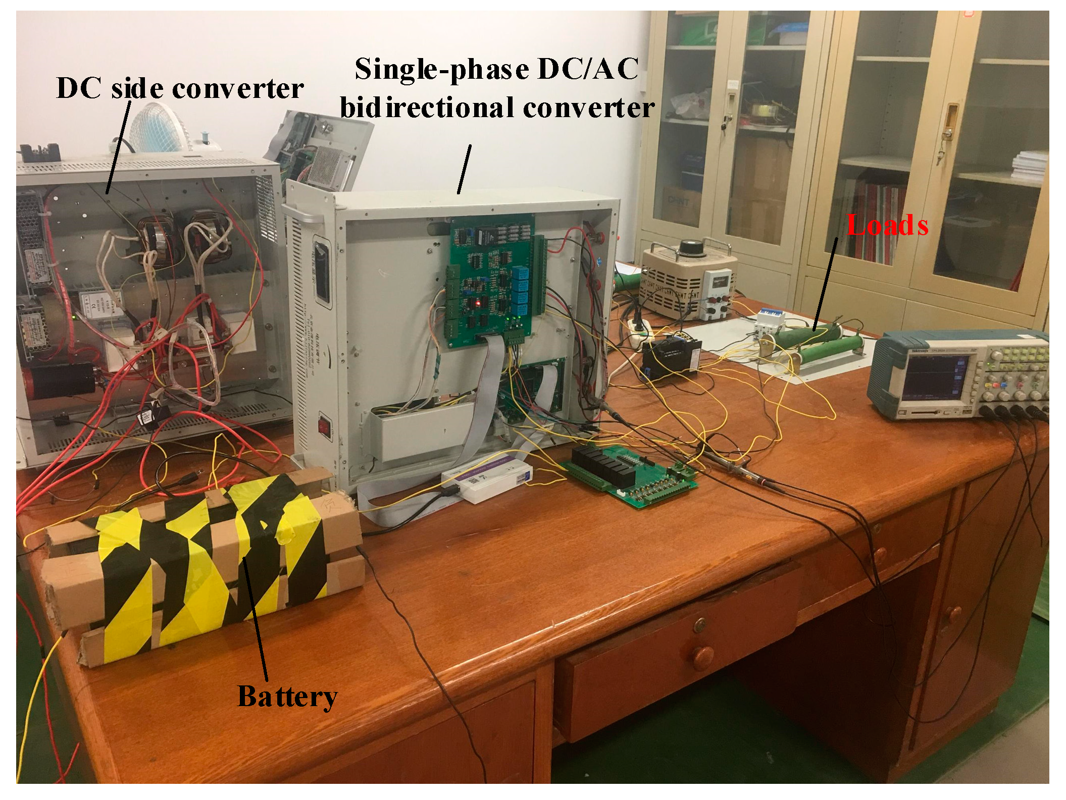
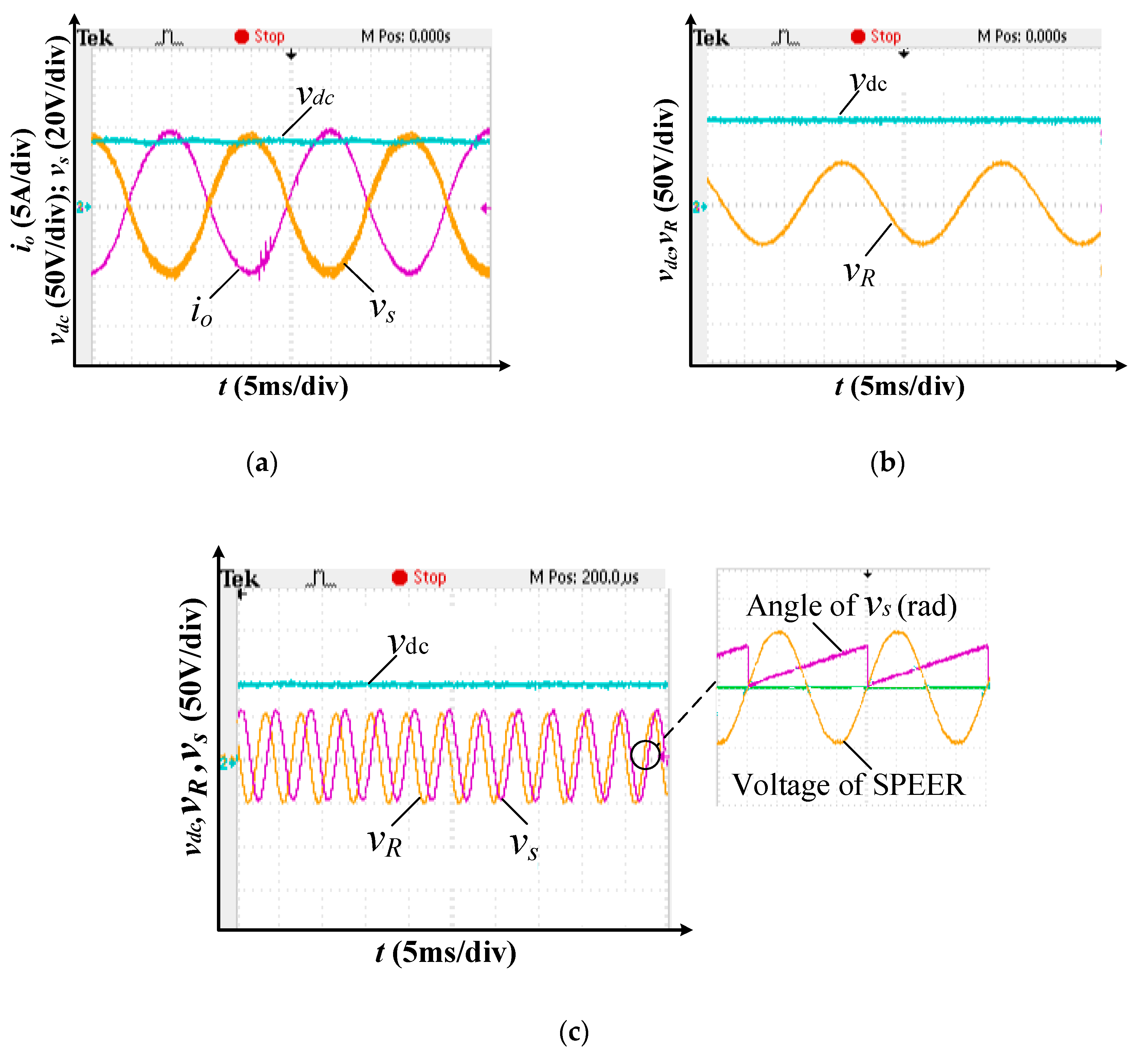
4. Experimental Verification

Based on the above research and analysis, the physical experiment platform is built for physical verification. The physical platform of the SPEER is shown in Figure 17.
The platform parameters built by physical objects are shown in Table 1.
Figure 18 shows the experimental waveforms of the SPEER. Among them, Figure 18a shows the grid-connected startup. The DC/AC bi-directional converter controls the DC bus voltage of 80 V and realizes the unit power factor control. Figure 18b shows the isolated network startup of SPEER. The battery controls the DC bus voltage to 80 V, and the DC/AC bi-directional converter operates in the inverter state. When the grid returns to normal, the system issues a grid-connected command, and the SPEER first performs grid-connected pre-synchronization. The experimental waveforms of the pre-synchronization process are shown in Figure 18c.
Figure 19 shows waveforms of a SPEER changed to a given power outer loop control strategy after it is connected to the grid. At this time, the SPEER can issue quantitative active and reactive power according to the upper control command and the current state of the battery, thereby achieving certain optimization goals. Moreover, the active and reactive power at this time are independent of each other.
Figure 20 shows the experimental waveforms of automatic off-grid switching when an isolated island is detected during the operation of SPEER. According to the experimental waveform, the SPEER completes off-grid switching and control strategy conversion in a relatively short time. Although there are short-term voltage and current fluctuations in the middle, the overall operation is stable and ensures the continuous power supply of important loads.

5. Conclusions

In this paper, a SPEER is designed from the practical point of view. It has plug-and-play, power routing, islanding detection, synchronization, and other functions. The detailed control strategies are given for each part of the SPEER. On this basis, the overall control strategies of the SPEER under the two working conditions of isolated network and grid-connection are given. The experimental results prove that the SPEER designed in this paper has the following functions:
1. When the power grid is in normal operation, the energy storage subsystem, the DC/AC bidirectional converter and new energy system (photovoltaic power system) make the best use of new energy under the premise of ensuring the power quality of the system through the seamless coordination of control strategies.
2. When a fault occurs in the power grid, the SPEER can quickly and accurately judge the fault and adopt an isolated network operation strategy, which can not only isolate the power grid fault but also guarantee the power supply reliability of important loads to a certain extent.
3. After the power grid fault is removed, SPEER can achieve grid connection without impact and uninterrupted power supply to the loads through the pre-synchronous control strategy, which improves the stability of the system and further guarantees the power supply reliability of important loads.
The Smart Grid represents the future of the power system [30]. The SPEER and its control strategy designed and studied in this paper can be well applied in a Smart Grid/Smart House. The access of distributed power equipment to SPEER makes the power supply of the home power system more flexible and diverse and integrates various renewable energy sources [31]. At the same time, its rich electrical interface better meets the increasing demand for electricity in household appliances, and advanced control strategies ensure the power quality of the system. The addition of energy storage devices improves the power supply reliability of important loads and reduces the influence of randomness and uncertainty, the inherent characteristics of new energy, on the system to some extent. Most importantly, the rationality of the structural design makes it possible to upgrade the original household electric power system with very little modification, making it more practical and feasible for ordinary families to upgrade to a “Smart House”.

Author Contributions

The authors contribute as follows: conceptualization, G.Z.; methodology, G.Z., C.J.; software, C.J.; validation, G.Z., C.J., J.L.; formal analysis, J.C., J.L.; investigation and resources, C.J., J.L.; data curation, C.J., J.L.; writing—original draft preparation, G.Z., C.J.; writing—review and editing, C.J., J.L.; supervision, G.Z.; project administration, G.Z.

Funding

This research was funded by the National Key R&D Program of China, 2017YFB0903100, and the Science and Technology Projects of State Grid Corporation of China, 521104170043.

Conflicts of Interest

The authors declare no conflict of interest.

References

  1. Miao, J.; Zhang, N.; Kang, C.; Wang, J.; Wang, Y.; Xia, Q. Steady-State Power Flow Model of Energy Router Embedded AC Network and Its Application in Optimizing Power System Operation. IEEE Trans. Smart Grid 2018, 9, 4828–4837. [Google Scholar] [CrossRef]
  2. Yang, F.; Bai, C.F.; Zhang, Y.B. Research on the Value and Implementation Framework of Energy Internet. Proc. CSEE 2015, 35, 3495–3502. [Google Scholar]
  3. Lasseter, R.H. MicroGrids. In Proceedings of the 2002 IEEE Power Engineering Society Winter Meeting. Conference Proceedings (Cat. No.02CH37309), New York, NY, USA, 27–31 January 2002; Volume 1, pp. 305–308. [Google Scholar]
  4. Huang, A.Q.; Crow, M.L.; Heydt, G.T.; Zheng, J.P.; Dale, S.J. The Future Renewable Electric Energy Delivery and Management (FREEDM) System: The Energy Internet. Proc. IEEE 2011, 99, 133–148. [Google Scholar] [CrossRef]
  5. Zhou, X.; Wang, F.; Ma, Y.; Gao, Z.; Wu, Y.; Yin, J.; Xu, X. An overview on energy router based on various forms of energy. In Proceedings of the 2016 Chinese Control and Decision Conference (CCDC), Yinchuan, China, 28–30 May 2016; pp. 2901–2906. [Google Scholar]
  6. Zong, S.; He, X.N.; Wu, J.D.; Li, W.H.; Zhao, R.X. Overview of Power Electronics Based Electrical Energy Router. Proc. CSEE 2015, 35, 4559–4570. [Google Scholar]
  7. Feng, G.; Zhao, Z.; Yuan, L.; Li, K. Combined DC voltage control scheme for three-port energy router based on instantaneous energy balance. In Proceedings of the 2016 IEEE Energy Conversion Congress and Exposition (ECCE), Milwaukee, WI, USA, 18–22 September 2016; pp. 1–7. [Google Scholar]
  8. Kang, M.; Enjeti, P.N.; Pitel, I.J. Analysis and design of electronic transformers for electric power distribution system. IEEE Trans. Power Electron. 1999, 14, 1133–1141. [Google Scholar] [CrossRef]
  9. Zhao, T.; Yang, L.; Wang, J.; Huang, A.Q. 270 kVA Solid State Transformer Based on 10 kV SiC Power Devices. In Proceedings of the 2007 IEEE Electric Ship Technologies Symposium, Arlington, VA, USA, 21–23 May 2007; pp. 145–149. [Google Scholar]
  10. Chen, L.; Sun, Q.; Zhao, L.; Cheng, Q. Design of a novel energy router and its application in energy internet. In Proceedings of the 2015 Chinese Automation Congress (CAC), Wuhan, China, 27–29 November 2015; pp. 1462–1467. [Google Scholar]
  11. Ren, L.; Zhang, C.; Du, M. Power router based on conventional three-phase bridge inverter and DC–DC converter. CIRED Open Access Proc. J. 2017, 2017, 391–394. [Google Scholar] [CrossRef]
  12. Lai, J.S.; Maitra, A.; Mansoor, A.; Goodman, F. Multilevel intelligent universal transformer for medium voltage applications. In Proceedings of the Fourtieth IAS Annual Meeting, Conference Record of the 2005 Industry Applications Conference, Kowloon, Hong Kong, 2–6 October 2005; Volume 3, pp. 1893–1899. [Google Scholar]
  13. Zhao, T.; Wang, G.; Bhattacharya, S.; Huang, A.Q. Voltage and Power Balance Control for a Cascaded H-Bridge Converter-Based Solid-State Transformer. IEEE Trans. Power Electron. 2013, 28, 1523–1532. [Google Scholar] [CrossRef]
  14. Li, Z.X.; Wang, P.; Chu, Z.F.; Zhu, H.B.; Li, Y.H. Research on Medium- and High-Voltage Smart Distribution Grid Oriented Power Electronic Transformer. Power Syst. Technol. 2013, 37, 2592–2601. [Google Scholar]
  15. Han, J.Y.; Li, Y.; Cao, Y.J.; Luo, L.F.; Duan, Y.L. A new modular multilevel type solid state transformer with internal model control method (in Chinese). Sci. Sin. Technol. 2016, 46, 518–526. [Google Scholar]
  16. Lingdong, K.; Jinghong, Z.; Wenzhi, Z.; Zeming, Z. Analysis of typical configuration scheme of micro-grid based on the electric energy router. In Proceedings of the 2017 China International Electrical and Energy Conference (CIEEC), Beijing, China, 25–27 October 2017; pp. 704–709. [Google Scholar]
  17. Liu, Y.S.; Ma, C. The Power Router Based on Hybrid AC/DC Microgrid Framework. Mod Electr. Power 2015, 32, 13–18. [Google Scholar]
  18. Liu, J.; Tang, F.; Wang, M.; Chen, P.; Xu, Z.; Wu, L.; Wang, W. A home energy router and energy management strategy for AC/DC hybrid sources and consumers. In Proceedings of the 2018 13th IEEE Conference on Industrial Electronics and Applications (ICIEA), Wuhan, China, 31 May–2 June 2018; pp. 1498–1503. [Google Scholar]
  19. Liu, Y.; Bi, C.; Zhao, Y.; Wu, Y.; Chen, X. Energy Router with Load Switching Functionality. Energy Procedia 2019, 158, 2561–2566. [Google Scholar] [CrossRef]
  20. Xu, X.; Hu, Y.; Tai, N.; Fan, C.; Geng, Q. A reliable distribution network structure with the use of electric energy router. In Proceedings of the 2017 IEEE Conference on Energy Internet and Energy System Integration (EI2), Beijing, China, 26–28 November 2017; pp. 1–3. [Google Scholar]
  21. Xu, Y.; Zhang, J.; Wang, W.; Juneja, A.; Bhattacharya, S. Energy router: Architectures and functionalities toward Energy Internet. In Proceedings of the 2011 IEEE International Conference on Smart Grid Communications (SmartGridComm), Brussels, Belgium, 17–20 October 2011; pp. 31–36. [Google Scholar]
  22. Hussain Nengroo, S.; Umair Ali, M.; Zafar, A.; Hussain, S.; Murtaza, T.; Junaid Alvi, M.; Raghavendra, K.; Jee Kim, H. An Optimized Methodology for a Hybrid Photo-Voltaic and Energy Storage System Connected to a Low-Voltage Grid. Electronics 2019, 8, 176. [Google Scholar] [CrossRef]
  23. Monfared, M.; Golestan, S. Control strategies for single-phase grid integration of small-scale renewable energy sources: A review. Renew. Sustain. Energy Rev. 2012, 16, 4982–4993. [Google Scholar] [CrossRef]
  24. Ciobotaru, M.; Teodorescu, R.; Blaabjerg, F. A new single-phase PLL structure based on second order generalized integrator. In Proceedings of the 2006 37th IEEE Power Electronics Specialists Conference, Jeju, Korea, 18–22 June 2006; pp. 1–6. [Google Scholar]
  25. Watanabe, E.H.; Stephan, R.M.; Aredes, M. New concepts of instantaneous active and reactive powers in electrical systems with generic loads. IEEE Trans. Power Deliv. 1993, 8, 697–703. [Google Scholar] [CrossRef]
  26. Samerchur, S.; Premrudeepreechacharn, S.; Kumsuwun, Y.; Higuchi, K. Power control of single-phase voltage source inverter for grid-connected photovoltaic systems. In Proceedings of the 2011 IEEE/PES Power Systems Conference and Exposition, Phoenix, AZ, USA, 20–23 March 2011; pp. 1–6. [Google Scholar]
  27. Liao, Z.L.; Ruan, X.B. Energy Management Control Strategy for Stand-alone Photovoltaic Power System. Proc. Chin. Soc. Elect. Eng. 2009, 29, 46–52. [Google Scholar]
  28. Zhang, L.; Yun, L.; Sun, M.; Peng, B. Simulation Research on Auxiliary Power Supply System of China Standard EMU. Electronics 2019, 8, 647. [Google Scholar] [CrossRef]
  29. Yu, B. An Improved Frequency Measurement Method from the Digital PLL Structure for Single-Phase Grid-Connected PV Applications. Electronics 2018, 7, 150. [Google Scholar] [CrossRef]
  30. Gheorghe, S.; Golovanov, N.; Lazaroiu, G.; Porumb, R. Smart Grid, Integration of Renewable Sources and Improvement of Power Quality. In Proceedings of the 2017 21st International Conference on Control Systems and Computer Science (CSCS), Bucharest, Romania, 29–31 May 2017; pp. 641–645. [Google Scholar]
  31. Vatu, R.; Ceaki, O.; Golovanov, N.; Porumb, R.; Seritan, G. Analysis of storage technologies within smart grid framework. In Proceedings of the 2014 49th International Universities Power Engineering Conference (UPEC), Cluj-Napoca, Romania, 2–5 September 2014; pp. 1–5. [Google Scholar]
Figure 1. Structure of the single-phase electric energy router (SPEER).
Electronics 08 00970 g001
Figure 2. The single-phase DC/AC bidirectional converter works in the inverter state.
Electronics 08 00970 g002
Figure 3. Block diagram of V/f control strategy for single-phase DC/AC bi-directional converter.
Electronics 08 00970 g003
Figure 4. Single-phase DC/AC bi-directional converters work in grid-connected mode. (a) Equivalent diagram of single-phase DC/AC bi-directional converter. (b) General vector diagram of single-phase DC/AC bi-directional converter.
Electronics 08 00970 g004
Figure 5. Block diagram of PQ control strategy with power as outer loop.
Electronics 08 00970 g005
Figure 6. Block diagram of PQ control strategy with DC voltage as outer loop.
Electronics 08 00970 g006
Figure 7. Block diagram of the overall control strategy for a single-phase DC/AC bidirectional converter.
Electronics 08 00970 g007
Figure 8. Control strategy block diagram of battery controlling DC bus voltage.
Electronics 08 00970 g008
Figure 9. Battery charging management scheme: (a) Block diagram of energy storage battery control strategy during charging. (b) Energy storage battery charging stage diagram.
Electronics 08 00970 g009
Figure 10. Control strategy for SPEER grid-connected pre-synchronization.
Electronics 08 00970 g010
Figure 11. Island detection control block diagram.
Electronics 08 00970 g011
Figure 12. Power flow of SPEER in isolated network Figure 1.
Electronics 08 00970 g012
Figure 13. Power flow of SPEER in isolated network Figure 2.
Electronics 08 00970 g013
Figure 14. Operation control flow chart of SPEER under isolated network.
Electronics 08 00970 g014
Figure 15. SPEERs are connected to the grid: (a) power flow chart; (b) control flow chart.
Electronics 08 00970 g015
Figure 16. Flow chart of overall operation control of SPEER.
Electronics 08 00970 g016
Figure 17. Photo of laboratory prototype of SPEER.
Electronics 08 00970 g017
Figure 18. Experimental waveforms when SPEER starts: (a) grid-connected startup; (b) isolated network startup; (c) grid-connected pre-synchronization.
Electronics 08 00970 g018
Figure 19. Experimental waveforms of the given power control strategy for SPEER: (a) the active power is 100 W; the reactive power is 0 Var; (b) the active power is 80 W; the reactive power is 50 Var.
Electronics 08 00970 g019
Figure 20. Experimental waveforms of SPEER switching from grid-connected to isolated network when isolated island occurs.
Electronics 08 00970 g020
Table 1. Parameters of each part of SPEER.
ComponentParameterValue
PhotovoltaicPeak power400 W
BatteryNominal capacity
Rated voltage
SOC min
SOC max
Constant charge voltage
Floating charging voltage
Constant charge current
Maximum charging current
7.2 A·h
48 V
0.2
0.95
58 V
56 V
2 A
2.88 A
DC busRated voltage
Capacitor size
80 V
2200 μF
AC busRated voltage amplitude
Rated frequency
50 V
50 Hz
AC power interfaceAdjustable power0–200 W
Adjustable DC load interfaceAdjustable voltage20–80 V, DC
LoadDC load (critical load)
DC load (non-critical load)
AC load (critical load)
AC load (non-critical load)
50 W
100 W
50 W
100 W
Filter inductorsL1, L, L3
L4
2.5 mH
6 mH
Filter capacitorsC1, C2, C330 μF
IGBTCollector-emitter maximum rated voltage1200 V
Continuous DC collector current75 A
Collector-emitter saturation voltage1.85 V
Gate threshold voltage5.8 V
Gate-emitter peak voltage±20 V
Operating frequency10,000 Hz
DiodeRepetitive peak reverse voltage1200 V
Continuous DC forward current75 A
Forward voltage1.7 V

