Article

Wearable Travel Aid for Environment Perception and Navigation of Visually Impaired People

1
School of Electronic Information Engineering, Beihang University, No. 37, Xueyuan Rd., Haidian Distrct, Beijing 10083, China
2
Department of AI, CloudMinds Technologies Inc., Beijing 100102, China
3
China Academy of Telecommunication Technology, Beijing 10083, China
*
Author to whom correspondence should be addressed.
Electronics 2019, 8(6), 697; https://doi.org/10.3390/electronics8060697
Submission received: 31 May 2019 / Revised: 18 June 2019 / Accepted: 19 June 2019 / Published: 20 June 2019
(This article belongs to the Special Issue Wearable Electronic Devices)

Abstract

:
Assistive devices for visually impaired people (VIP) which support daily traveling and improve social inclusion are developing fast. Most of them try to solve the problem of navigation or obstacle avoidance, and other works focus on helping VIP to recognize their surrounding objects. However, very few of them couple both capabilities (i.e., navigation and recognition). Aiming at the above needs, this paper presents a wearable assistive device that allows VIP to (i) navigate safely and quickly in unfamiliar environment, and (ii) to recognize the objects in both indoor and outdoor environments. The device consists of a consumer Red, Green, Blue and Depth (RGB-D) camera and an Inertial Measurement Unit (IMU), which are mounted on a pair of eyeglasses, and a smartphone. The device leverages the ground height continuity among adjacent image frames to segment the ground accurately and rapidly, and then search the moving direction according to the ground. A lightweight Convolutional Neural Network (CNN)-based object recognition system is developed and deployed on the smartphone to increase the perception ability of VIP and promote the navigation system. It can provide the semantic information of surroundings, such as the categories, locations, and orientations of objects. Human–machine interaction is performed through audio module (a beeping sound for obstacle alert, speech recognition for understanding the user commands, and speech synthesis for expressing semantic information of surroundings). We evaluated the performance of the proposed system through many experiments conducted in both indoor and outdoor scenarios, demonstrating the efficiency and safety of the proposed assistive system.

1. Introduction

According to the global statistics of the World Health Organization (WHO), 188.5 million people have mild vision impairment, 217 million people have moderate to severe vision impairment, and 36 million people are blind [1]. Vision impairment has a significant impact on lives, including the ability to navigate and recognize the environment independently. Aside from achievement of medicine, neuroscience, and biotechnologies to find an ultimate solution to vision impairment problems [2], electronic and computer technologies can provide assistive tools to improve their quality of life and allow better integration into society.
A survey [3] of 57 visually impaired people, their care givers, and rehabilitation professionals found that the visually impaired persons (VIPs) require and expect an electronic assistive device with (1) adequate information of the surroundings; (2) a simple user interface; (3) light weight; (4) safety; and (5) cost effectiveness. To satisfy the above needs, many electronic assistive devices [4,5,6,7] have been proposed in recent years. These designs can be classified into two categories from an overall perspective. One is for guidance/navigation and the other one is for recognizing the nature of nearby obstacles/objects. However, very few of them couple both functionalities (i.e., navigation and recognition) [2], or apply recognition technology to navigation system [8]. Integrating recognition and navigation capabilities into a single system can dramatically improve the VIP’s daily traveling. For example, a navigation system without a recognition function may understand a chair as an obstacle when it is helping a blind person to look for a seat, or find no path to enter a room with closed doors. However, if the recognition capability is present, it will help the VIP to find the chair to sit, or open the door to enter the room.
With the aim of addressing the above needs, this paper proposes a new design that incorporates navigation and recognition capabilities into a single prototype (see Figure 1). The device is based on computer-vision technologies due to the vision sensor’s characteristic of adequate information, light weight, and low cost compared to other sensors, such as ultrasonic and LiDAR sensors [9] that many early assistive devices used. The components of this device include a consumer Red, Green, Blue, and Depth (RGB-D) camera attached to a pair of eyeglasses, an Inertial Measurement Unit (IMU) attached to a camera, a smartphone, and an earphone for commands/feedback. The system can work in both indoor and outdoor environments. As soon as the device is powered on, the navigation module will work to instruct the VIP whenever he/she wants to go to a place. To avoid information overload, the recognition module is activated according to the user requirement via a simple action of double-tapping the smartphone screen. The prototype was implemented and tested in both indoor and outdoor environments, and the results show good performance in terms of both navigation and recognition efficiency, and provides a good traveling experience for VIPs.
The main contributions of this work are as follows:
  • Design a lightweight Convolutional Neural Network (CNN)-based 2.5D object-recognition module which combines depth image-based object-detection method to provide obstacles’ category, location, and orientation information, and integrate this module into our previous work [10,11] to improve the environment perception ability of VIP and promote navigation.
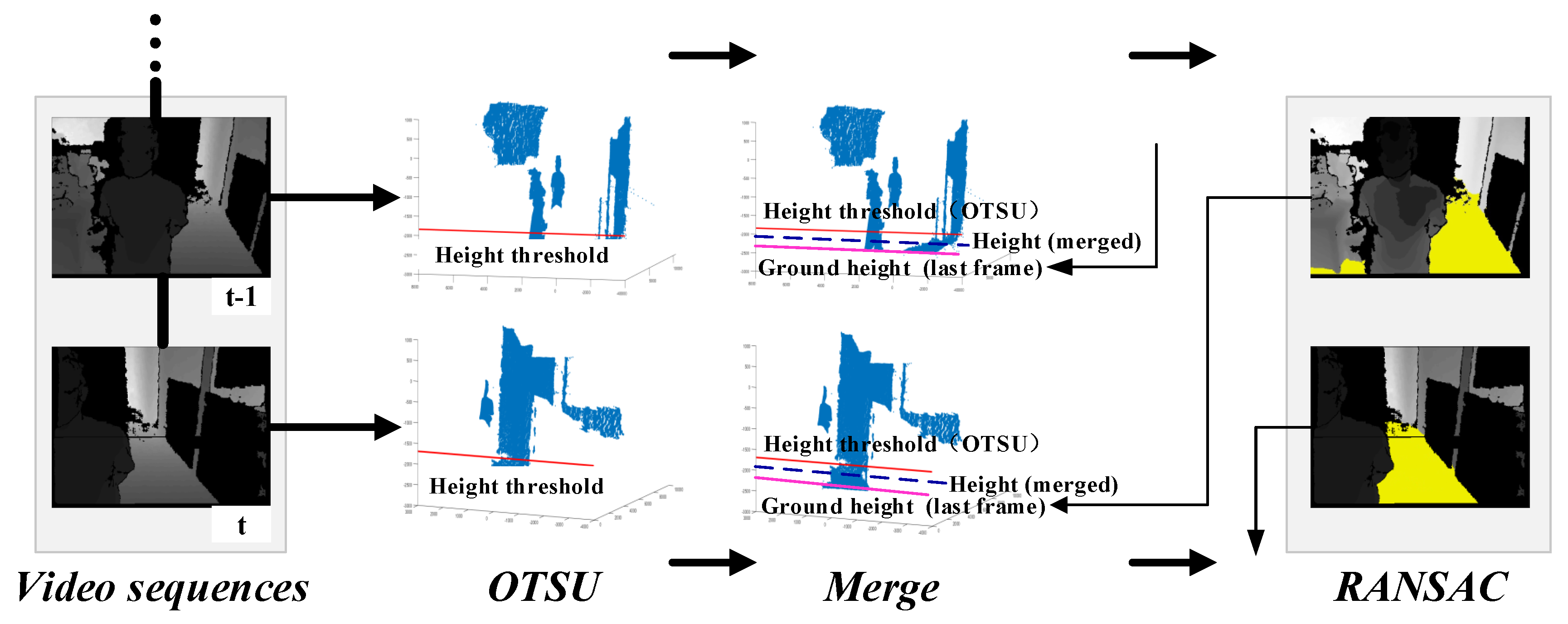
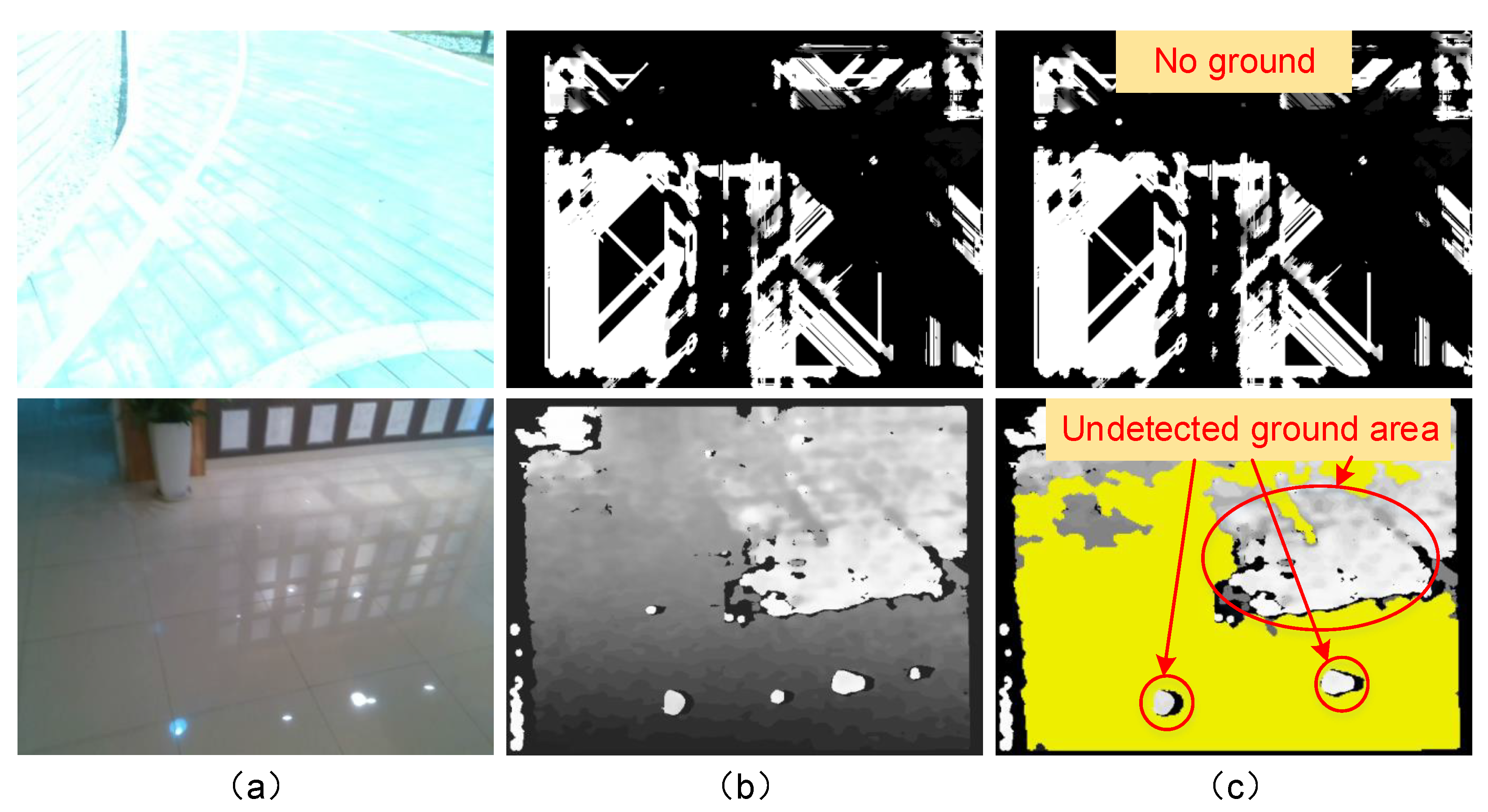
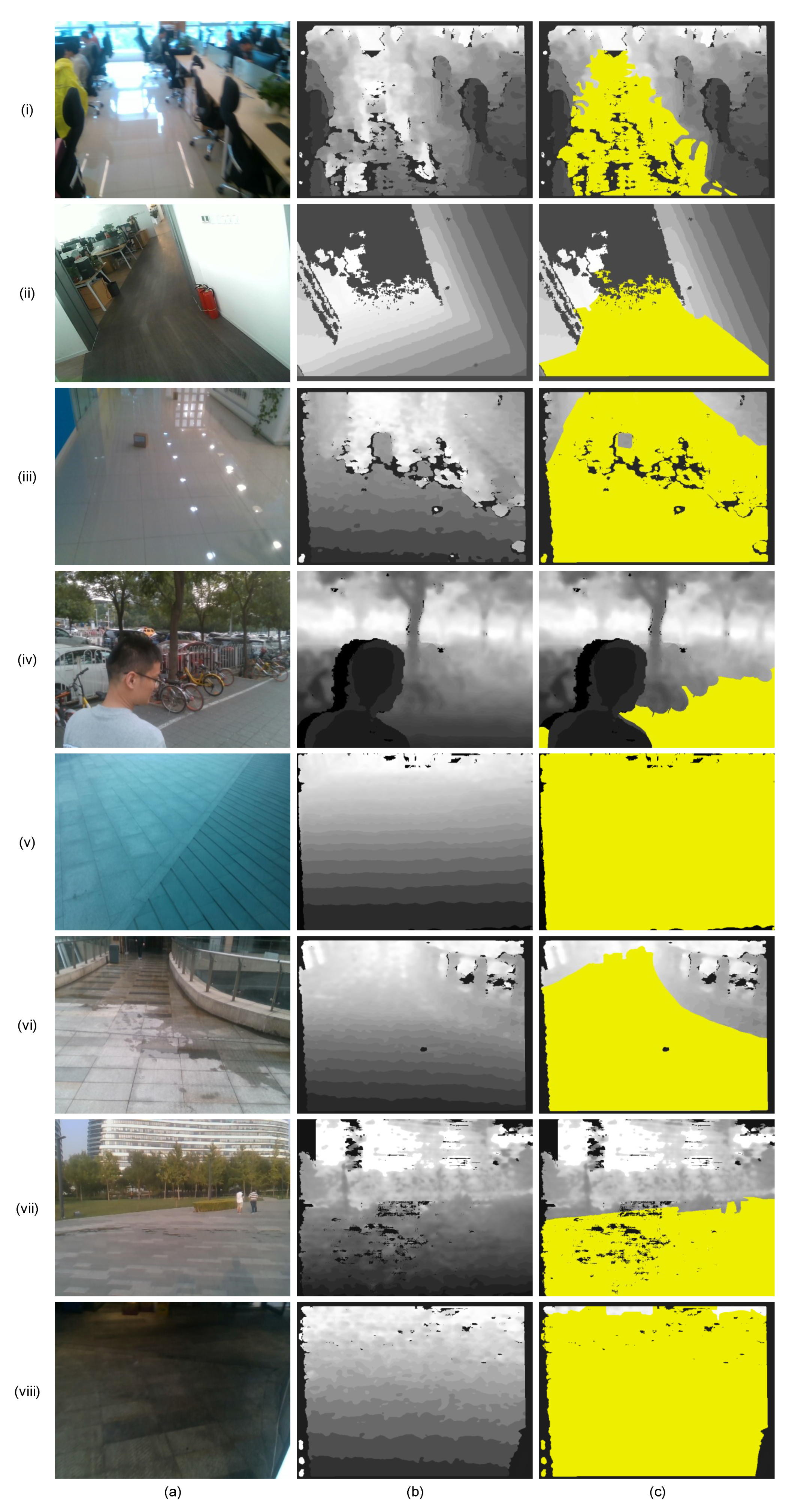
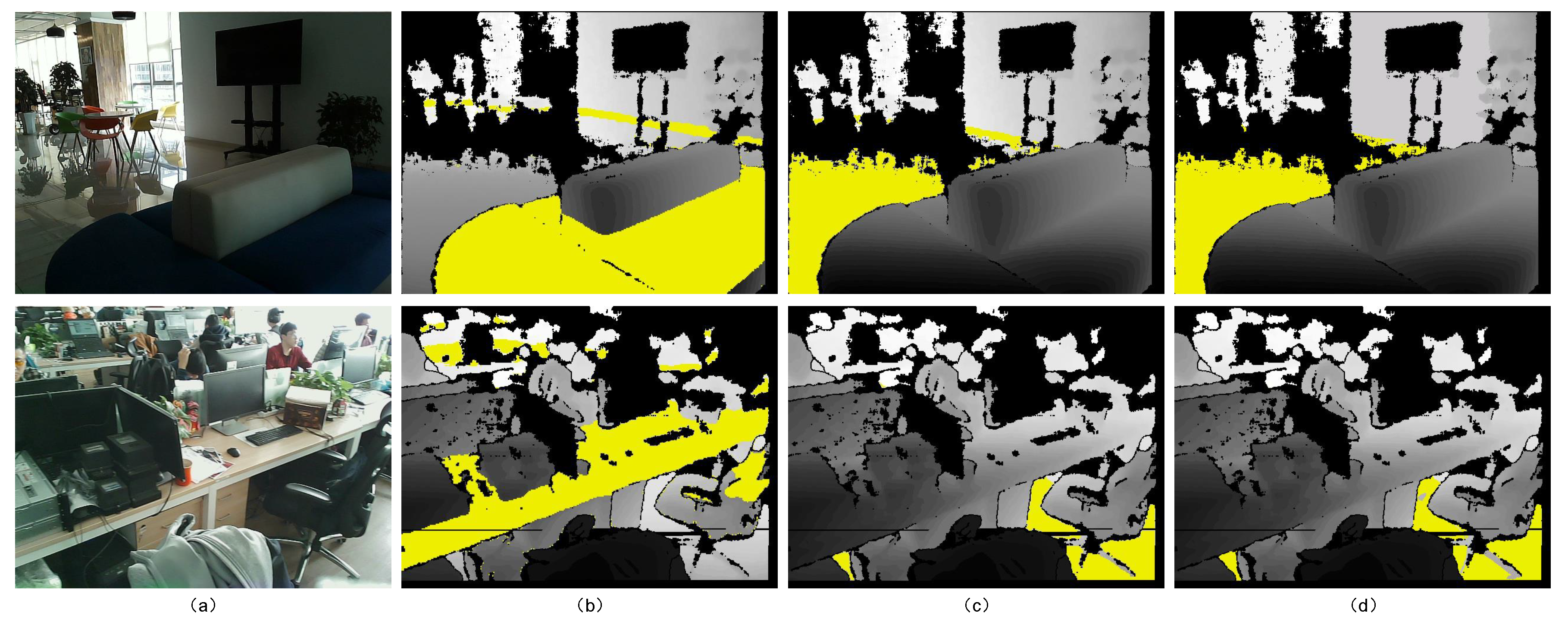
  • Propose an adaptive ground segmentation algorithm that uses an adaptive threshold computation algorithm and uses ground height continuity among adjacent frames.
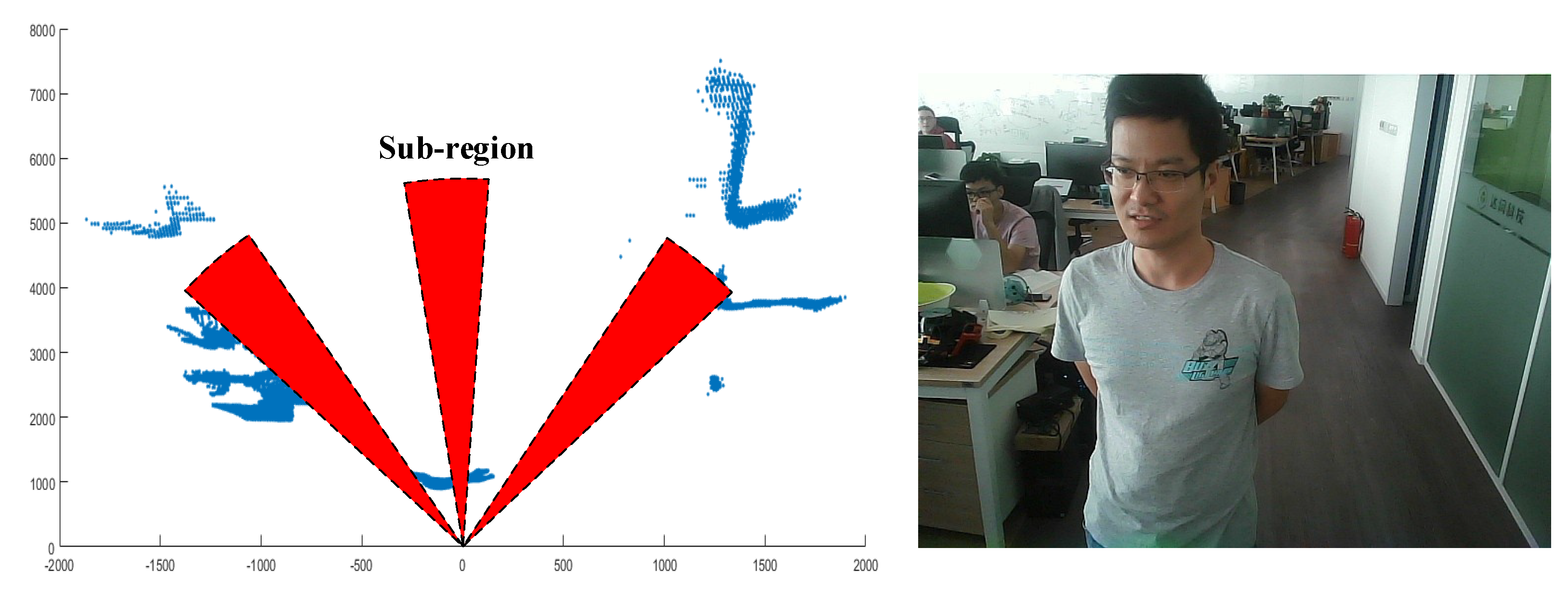
  • Present a walkable direction search method to guide VIP to his/her destination.
  • Expand our previous work [10,11] to allow the system to be applied in outdoor scenarios.
The remainder of this paper has been divided into four sections. The related previous works are presented in Section 2. In Section 3, the proposed system is introduced and described in detail. Subsequently, in Section 4, the system performance is tested and discussed in both indoor and outdoor environments. Finally, the conclusions, along with some ideas of future, study are given in Section 5.

2. Related Work

In this section, the relevant works on vision-based navigation and recognition systems for VIPs in the past six years are introduced. In addition, we focus object recognition on the deep-learning-based methods that are very popular in computer vision and robotics communities.

2.1. Vision-Based Assistive Systems for VIPs

Vision-based assistive systems use different types of camera, such as mono camera, stereo camera, and RGB-D camera, to capture images from the real-world environment, and use computer vision-based algorithms such as segmentation, edge detection, and image filtering to detect obstacles.
A wearable tool was designed in [12] to provide navigation assistance for VIP in indoor and outdoor scenarios by perceiving the environment and traffic situations such as street crossings, traffic lights, cars, and other obstacles. It uses a stereo camera and generates audio signals for navigation. It detects a free path under the assumption that the texture of the free path remains the same in the approaching meters, and the largest plane in the image is the ground. As a result, changes to ground texture or other large planes (e.g., a wall or a table) may cause errors in free path detection. Furthermore, the data processing unit is limited to video inputs.
A navigation system for VIP was presented in [13] that uses an RGB-D camera to detect obstacles. It not only identifies hurdles through corner detection, but also offers a safe path to the left or right side. Voice synthesis is used to alert the users. However, the system has no recognition capability and the obstacle detection performance degrades severely under strong sunlight.
A new obstacle detection method in a Deformable Grid (DG) structure was proposed in [14,15] to aid VIP. It detects an obstacle in danger of a crash according to the level of DG deformation. It uses an RGB camera to capture video sequences which then will be sent to a laptop for processing. The resulting signal is conveyed to the user’s earphone via Bluetooth technology. In [15], a vertex deformation function was used to improve the performance of the previous work [14] in terms of accuracy and processing time. However, it cannot detect obstacles that are closed to non-textured regions such as a door or a wall.
A wearable device in [16] expanded the detection of the traversable area by using an RGB-D camera. RANdom SAmple Consensus (RANSAC) segmentation and surface normal vector estimation are used to obtain the traversable area. The device provides a non-semantic stereophonic interface to transfer the traversable area-detection results to the VIP. It can operate in both indoor and outdoor environments. However, the proposed prototype has heavy computation, which is very difficult for real-time operation, and only detects the traversable area within a short range. Later, the same author designed a deep learning-based pixel-wise semantic segmentation method in [17] to help VIPs perceive terrain such as traversable area, stairs, water hazards, and sidewalks. However, the system needs a graphics processing unit (GPU) to accelerate the processing of semantic segmentation.
A prototype [2] was developed to provide the capabilities of autonomous navigation and object recognition in indoor scenarios for VIPs. The system integrates a headset, camera, IMU, and laser sensors that are placed on the user’s chest. The user interface is via speech recognition and synthesis modules. In order to recognize objects, the system first learns the image similarity via a bundle of Gaussian Process Regressors (GPR) and then uses GPR to assess the similarity between the captured image in a new scene and the training images. Consequently, it requires prior information about indoor environments to train the GPR, which limits its universal application in other scenarios.
A new navigation system for VIP was introduced in [9] by using an RGB-D camera to collect visual and range information from the surroundings. It fuses range and color information to detect obstacle-free paths and classifies the main structural elements of the scene for safe navigation across unknown environments. It sends navigation commands to the users via a sound map which is created by stereo beeps and voice commands. However, the algorithm is complicated and runs at just 0.3 fps. In addition, the system only operates in indoor environments.
A Co-Robotic Cane (CRC) was presented in [18] that uses a three-dimensional (3-D) camera for pose estimation and object recognition in an unknown indoor environment. The camera’s pose change is determined by visual range odometry (VRO) and the iterative closest point (ICP) algorithm. The object-recognition method detects indoor structures such as stairways and doorways, and objects such as tables and chairs, by a Gaussian mixture model (GMM)-based pattern-recognition method. Later, the CRC’s developing team integrated a wayfinding function [19] into CRC for navigating VIP in an indoor environment. Recently, they presented a 3D object-recognition method to allow real-time indoor structural object detection [20]. The method segments the point cloud into different planar patches and classifies planes into the model objects. However, the system does not couple navigation and recognition capabilities, and does not show that the object recognition can improve the navigation.
A smartphone-based navigation system for VIP was designed in [21] that uses RGB camera, MEMS, and ultrasonic sensors to perceive the environment. It enables book reading, phone calls, and date and time searching, and communicates with users via a Text-to-Speech (TTS) module. However, the system does not optimize obstacle detection distance through many tests in indoor and outdoor scenarios.
A framework called Blind Guide for VIP was proposed in [22] to navigate VIP in indoor and outdoor environments by using wireless sensor networks. The system uses an RGB camera and ultrasonic sensor to detect obstacles and provide an audio signal as feedback. The system can identify chairs, tables, doors, and other objects in indoor environments via a cloud image recognition service. Thus, it only works in a scene with internet access and works well only with good light conditions.
A wearable system was proposed in [23] to provide situational awareness for VIP. The system uses a portable depth camera to extract surroundings’ information, such as obstacle range and direction, the free space, and the target object’s location and identity. Haptic feedback from vibration motors is used to provide navigation cues. However, the system applies to only indoor environments and recognizes only some common objects in engineered indoor scenes, e.g., tables, chairs, and loungers.
A monocular vision-based system was introduced in [24] to aid VIP in walking, running, and jogging. It uses an RGB camera to capture the images, and then processes the images to extract the lines/lanes. The alert signal is generated by a haptic device to notify the users to move left or right. However, it is not suitable in crowded scenarios due to its weak obstacle-avoidance capability.
A prototype was designed in [25] that aims to substitute the impaired eye of VIP. It uses a deep-learning-based object-recognition method to provide a situational overview of objects and guides the user via 3D audio feedback. However, the system has low recognition accuracies on small objects and needs network connection to provide the recognition service, which limits its mobility.
A sensor fusion system was presented in [26] that combines an RGB-D camera and millimeter wave (MMW) radar sensor to perceive the surrounding obstacles. It detects the position and velocity information of the multiple targets by MMW radar, and verifies the depth and position information of the obstacles through the MeanShift algorithm. It uses a non-semantic stereophonic interface to convey obstacle detection results to users. However, the prototype still runs on a PC, which is not portable, and lacks object recognition.
A holistic vision-based mobile assistive navigation system was developed in [27] to help VIP with indoor independent travel. It uses a visual positioning service within the Google Tango device and a semantic map to achieve semantic localization. A time-stamped map Kalman filter-based algorithm was developed to detect and avoid obstacles by using the RGB-D camera. The system has a multi-modal user interface that includes speech audio and haptic interaction. However, the semantic map needs annotation functionality to add points of interest (POI), which is not easily accessible for VIP.
A smart guiding eyeglass was developed in our previous work [11] that uses an RGB-D camera and ultrasonic sensors to detect obstacles in indoor environments. Later, the localization and navigation capabilities were integrated into the guiding eyeglass in [10]. However, the system cannot provide recognition capability and only works in indoor environments.
Table 1 summarizes the aforementioned vision-based assistive systems for VIP and evaluates some important parameters according to VIP’s requirements as mentioned in Section 1, such as sensors, feedback, weight, cost, and capabilities.

2.2. Deep Learning-Based Object Recognition for VIPs
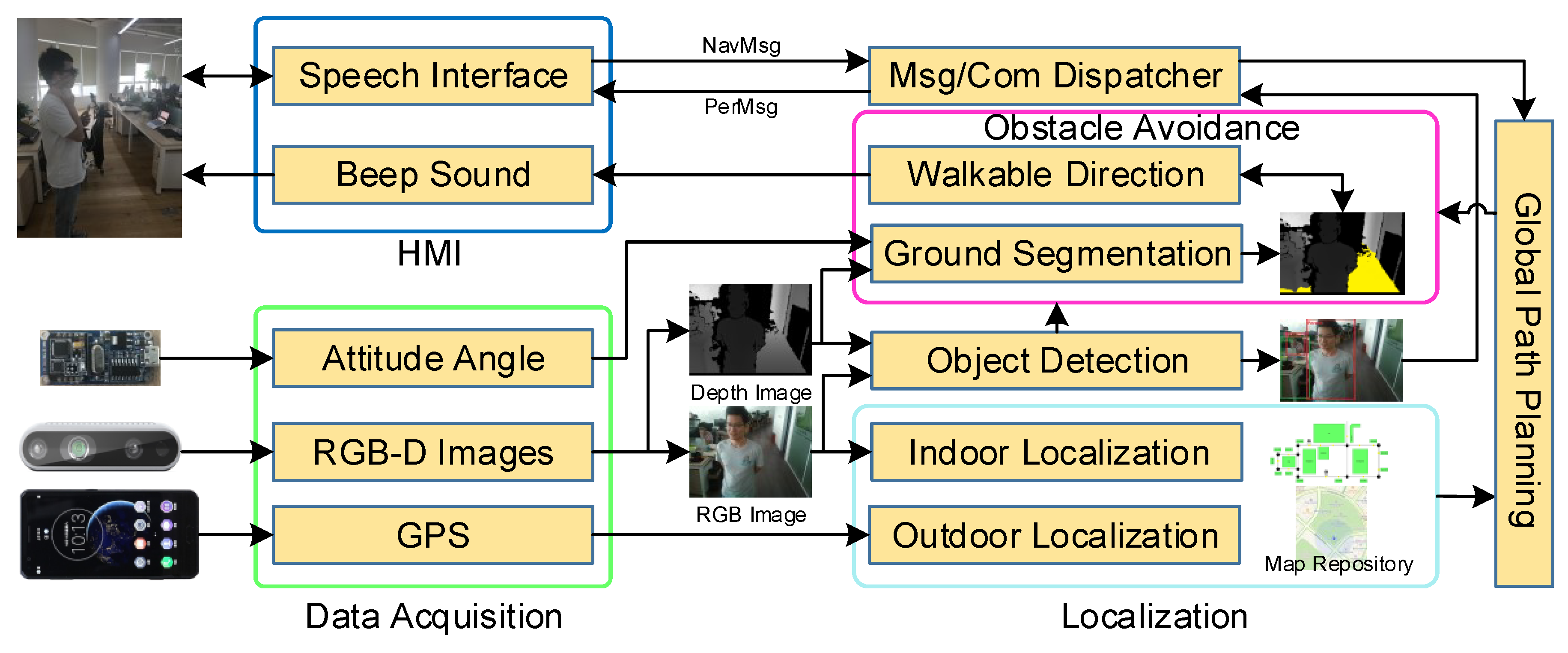
While object recognition initially was realized through aligning a 2D/3D model of the object on the image using simple features such as edges, key-points, or templates, the arrival of Machine Learning (ML) revolutionized the area. A real-time obstacle detection and classification system for safe navigation was designed in [28]. The system uses Scale Invariant Feature Transform (SIFT) and Features from Accelerated Segment Test (FAST) features to extract POI, and uses Support Vector Machine (SVM) and Bag of Visual Words (BoVW) to classify these points into four classes: vehicles, bicycles, pedestrians, and obstacles. However, the ML-based methods still rely on hand-crafted visual features processed by classifiers or regressors, which needs a lot of tests to find the optimized parameters that adapt to as many scenarios as possible.
Since AlexNet [29] won the ImageNet Challenge: ILSVRC 2012 [30], Deep CNN (DCNN)-based object-recognition methods have become unprecedentedly popular due to their strong feature-representing and -learning abilities. Several DCNN-based research works [31,32,33,34,35] have been conducted to recognize objects for VIP, helping them to move and perceive environments independently.
A DEEP-SEE framework was introduced in [31] that uses both computer-vision algorithms and DCNN to detect, recognize, and track objects encountered during navigation in the outdoor environment. The system designs two CNNs for considering both motion patterns and visual-object appearances, the results being that it needs an Ultrabook computer with a GPU to accelerate the tracking and recognition performance. Furthermore, it lacks the guiding system to help VIP to reach a desired destination.
A smartphone-based guiding system for VIP was developed in [32] that integrates a computer image recognition system and smartphone application. The smartphone captures images and sends the images to the backend server to recognize multiple obstacles in the images by using a faster region CNN algorithm. However, it is only able to recognize a few types of obstacles, and has a low recognition rate.
A deep learning-based visual-object recognition model was proposed in [33] to guide VIP in an outdoor environment. The deep CNN-based computing is performed on a cloud server with GPU, and can recognize 11 outdoor objects such as car, person, stair, and tree. The recognition results are transferred to the user in the form of voice via the hearing device attached to a smartphone. However, the depth information about objects is not embedded and a broader range of objects should be recognized.
A deep neural network-based algorithm was presented in [34] to assist VIP’s mobility in unfamiliar healthcare environments such as clinics, hospitals, stairs, and signage. However, the prototype cannot detect multiple objects in a single image, and the feedback is still under development.
A multi-modal and multi-label learning techniques-based method was proposed in [35] to assist VIP in recognizing objects in the indoor environment. The method associates appearance and depth cues, i.e., RGB-D images, to overcome the problems of traditional vision systems. However, it only focuses on object recognition and lacks the navigation capability.
A scene perception system was presented in [36] that classifies the objects along with their distances and provides a voice output to the users. The system uses a multi-modal fusion-based faster Recursive CNN (RCNN) that uses optical flow, edges, and scale-space features to recognize objects, and uses a laser sensor to extract the distances of the recognized objects. Nevertheless, the system is bulky and does not take the navigation into consideration.
The above systems focus on the recognition capability and performance, which results in the network having a large size and requiring high-performance hardware to be trained. Recently, lightweight CNN-based object-detection architectures such as SqueezeNet [37], Mobilenet [38], Xception [39], ShuffleNet [40], Mobilenetv2 [41] and PeleeNet [42], have been presented to improve the real-time performance of the aforementioned CNN architectures. As the PeleeNet [42] has a smaller model size and achieves relatively better recognition results than other lightweight networks, we design a PeleeNet-based 2.5-D object-detection method to extract the semantic information of surroundings, such as an obstacle’s category, distance, and orientation. This object-detection algorithm runs on a smartphone offline to cope with the poor network or network-less scenarios.

3. System Design

The system architecture is shown in Figure 2, consisting of six modules: data acquisition, localization, global path planning, obstacle avoidance, object detection, and human–machine interaction (HMI). The system has two main capabilities: navigation and recognition. The former works online and guides the VIP from the current location to the desired destination in both indoor and outdoor environments, while avoiding obstacles; however, the latter works on demand, e.g., when the VIP wants to find a seat or when some obstacles block his/her way. The inputs of the system include:
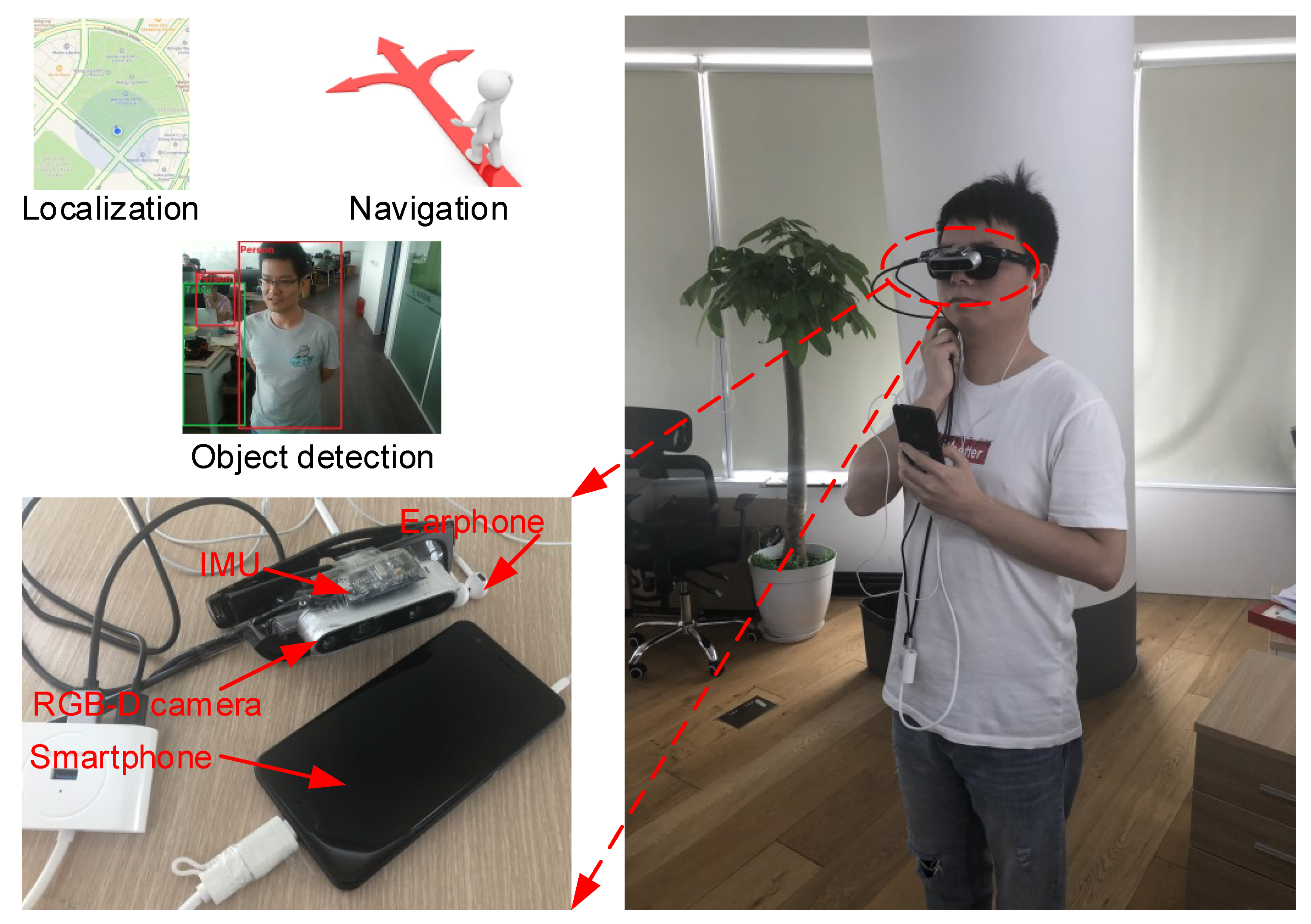
  • A speech interface module, which acquires and recognizes verbal instructions from the user, e.g., to indicate a desired destination.
  • An RGB-D camera (Intel RealSense D435), which captures the depth and color images in both indoor and outdoor scenarios and forwards the images to the navigation or recognition system.
  • An IMU sensor, used to acquire the attitude angle of the camera.
  • A smartphone, used to obtain the current position of the user in the outdoor environment, perform the navigation and object-recognition algorithms, and play the audio feedback.
  • A map repository including the indoor maps built by the Visual Simultaneous Localization and Mapping (VSLAM) technique [43,44] and outdoor maps provided by QQMap [45].
  • A dataset including many common objects such as chairs, desks, cars, pedestrians, etc., used in the recognition system.
The outputs of the system include:
  • A speech interface module to convert the output of navigation system into a beeping sound and the output of recognition system into speech.
  • The recognition system outputs the object’s category, distance, and orientation.
The various modules are described in detail in the following sections.

3.1. Navigation System

The navigation system includes three main modules, namely (1) a localization module that serves to estimate the user’s current location; (2) a global path-planning module whose function is to estimate a path from the current location (automatically detected by the localization module) to the desired destination (provided by the user); and (3) an obstacle-avoidance module which generates the walkable direction following the global path (planned by the global path-planning module).

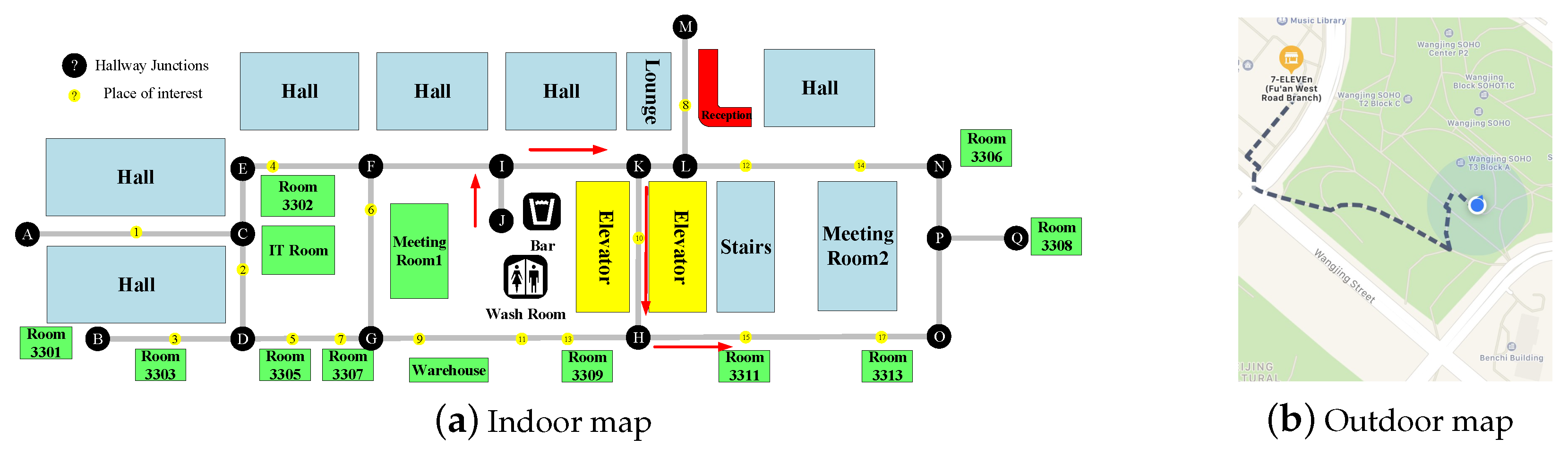
3.1.1. Localization Module

In indoor environments, the GPS-based localization techniques cannot be used due to the severe degradation of GPS signal. Hence, we use the VSLAM [44] to locate the user’s current location and build indoor maps, which is the same as our previous work [10]. The indoor maps (which actually are visual features maps) are built beforehand and loaded in the smartphone, then the localization module estimates the camera pose through matching the features extracted from the current image with previous features in the indoor maps.
In outdoor environments, we use the GPS module integrated in the smartphone to obtain the user’s current location. Because the GPS module’s update frequency cannot satisfy the real-time requirement in navigation for VIPs, we use a Kalman filter to perform a dead reckoning based on previous position provided by GPS module and current IMU measurements in a continuous manner [46].
The output of the localization module (i.e., the estimated spatial position of the camera in indoor environment, or the longitude and latitude position and the orientation in the outdoor environment) is finally fed to the global path-planning module.

3.1.2. Global Path-Planning Module

In indoor environments, as we use the VSLAM technique to build the map, which is not unified with the map in outdoor environments, the topological map (see Figure 3a) is used as per our previous work [10]. The global path-planning module collects the desired destination from the speech interface and the initial location from the localization module, and finds a shortest global path from the current location to the destination by using A* algorithm. An example of the planned path is shown in Figure 3a, the bar to the room3311: J->I->K->10->H->15, where the number or the letter represents the key place or intersection.
In outdoor environments, many mature services such as GoogleMap, QQMap, and BaiduMap can be used to plan a global path. To cope with the poor network or network-less scenarios, we use the QQMap service [45] for its capability for working offline. An example of the planned path is shown in Figure 3b, from the office building to the 7-Eleven which is depicted by the dashed line.
The output of the global path-planning module (i.e., a shortest path), is finally fed to the obstacle-avoidance module.

3.1.3. Obstacle-Avoidance Module

When following the global path, the VIP might encounter obstacles including static (e.g., walls, furniture, and trees) or moving (e.g., pedestrians, cars) objects. The static obstacles are typically part of the map (except for objects that can be temporarily moved), such that the global path-planning module has considered them. By contrast, the moving obstacles need to be detected online while guiding the VIP. Therefore, in this paper we proposed an obstacle-avoidance method that contains two stages: (1) ground segmentation; and (2) walkable direction search.
Adaptive Ground Segmentation: Firstly, the point cloud is reconstructed, which uses the depth image and the attitude angle of the camera. As shown in Figure 4, the camera coordinate system X c Y c Z c is centered at the camera, and the positive Z c -axis, Y c -axis, and X c -axis are defined as the camera’s facing direction, up direction and left direction, respectively. The world coordinate system X w Y w Z w is centered at the camera coordinate system center, the positive Z w -axis, Y w -axis, and X w -axis are the user’s facing direction, vertically upward direction, and left direction respectively. Both coordinate systems are the left-handed Cartesian coordinate systems. The pixel value of point p ( u , v ) in the depth image represents the distance between point P ( x , y , z ) and the camera, which is equal to z. With the camera attitude angle measured by the IMU, the corresponding 3-D point cloud in the world coordinate system can be calculated through:
x w y w z w = z E K 1 u v 1 E = cos γ sin γ 0 sin γ cos γ 0 0 0 1 1 0 0 0 cos α sin α 0 sin α cos α K = f x 0 u 0 0 f y v 0 0 0 1 ,
where K is the camera intrinsic parameter matrix, point ( x w , y w , z w ) is the reconstructed point in the world coordinate system, α is the camera pitch angle, and γ is the camera roll angle.
Secondly, the coarse ground is fitted via the adaptive threshold segmentation method OTSU [47] and RANSAC algorithm [48]. As shown in Figure 5, the initial ground height threshold T Y c u r is calculated adaptively using the OTSU algorithm in the current frame. Since the change of ground height in two adjacent frames is usually limited, the ground height T Y p r e of the previous frame is used to reduce the perturbation of other planes (e.g., desk, sofa). The final ground height threshold is computed as:
T Y = λ T Y c u r + ( 1 λ ) T Y p r e ,
where λ is a weight parameter. Due to the inherent limitation of the depth camera, the depth accuracy always drops down with the increase of distance. Besides, the obstacles that are too far away from the person do not need to be considered. Therefore, only the points within a threshold T Z are used to reduce computation cost. By making use of the ground height T Y and the distance threshold T Z , the 3-D points for fitting the coarse ground can be obtained through:
F i n i t = { p ( x , y , z ) | y < T Y , 0 < z < T Z } .
Then the coarse ground is fitted with RANSAC algorithm, and represented as:
A x + B y + C z + D = 0 .
Thirdly, the coarse ground is refined via surface roughness filtering. According to Equation (4), the normal vector n g r o u n d of coarse ground plane can be obtained directly, and the ground pitch angle ϕ is computed through:
ϕ = arccos ( n g r o u n d · n x o z n g r o u n d n x o z ) ,
where n x o z is the normal vector of plane X w O Z w . On the basis of the ground pitch angle and the empirical slope angle, the coarse ground will be classified as one of the four types: horizontal ( ϕ < 5 ° ), upslope ( 5 ° ϕ 30 ° ), downslope ( 30 ° ϕ 5 ° ), and non-ground ( ϕ 30 ° ). If it is non-ground, there is no need to refine it; otherwise, it will be refined by roughness filtering:
F = { p ( x , y , z ) | p F i n i t , d i s t ( p , F i n i t ) σ } d i s t ( p , F i n i t ) = A x + B y + C z + D A 2 + B 2 + C 2 ,
where σ is the unevenness tolerance, d i s t ( p , F i n i t ) is the distance from point p to the coarse ground, F is the final 3-D point cloud of refined ground. The refined ground point cloud F will be fed to walkable direction search module. Besides, the height H of the refined ground is calculated through:
H = 1 k i = 1 k y i , p i ( x i , y i , z i ) F ,
and it will be used in next frame, which speeds up the ground segmentation and increases the segmentation accuracy.
Optimal Walkable Direction Search: Based on the planned global path in Section 3.1.2 and the ground point cloud, we can find the optimal walkable direction to guide the VIP to his/her destination. Since the walkable direction must be located in the detected ground, we just consider the ground plane-based 3-D space, and first select the 3-D points within this space through:
P = { ( x i , y i , z i ) | min ( x ) P ( x , y , z ) F x i max ( x ) P ( x , y , z ) F , H y i H + D A 2 + B 2 + C 2 + ε , 0 z i max ( z ) P ( x , y , z ) F } ,
where F is the point cloud of the detected ground, H is the ground height, A , B , C , D are the plane parameters defined in Equation (4), and ε is a constant for preventing the person from being collided with overhanging obstacles.
Then the 3-D points P are projected onto the plane X w O Z w (see Figure 6). The nearest points in all sectors (each sector is represented as the sub-region in Figure 6 and the angle of each sub-region is 0.5 ° ) can be easily obtained. The cost of each sector is computed as:
n = 180 π arcsin w s w w s w z i z i θ c o s t [ i ] = α ( θ g o a l θ ( i N 2 ) ) a n g l e c o s t + β max j = i : i + n 1 z j d i s t a n c e c o s t ,
where θ is the angle of a sector, w s w is the passable width (greater than the person’s body width), z i is the z axis coordinate values of the nearest point in sector i, α and β are the weights, N is the total number of sectors, and θ g o a l is the direction that the VIP should follow, which is calculated by the same method in [10]. This cost function ensures that the person moves toward the direction of global path and with longer traversable distance.
Finally, the optimal walkable direction is obtained by:
γ = N o n e , i f z arg min i ( c o s t [ i ] ) < τ | | P = θ ( i min N 2 ) , e l s e ,
where τ is a distance threshold, z arg min i ( c o s t [ i ] ) is the nearest distance of the sector with the minimum cost, i min is the index of the sector with the minimum cost, N is the total number of sectors, and P is the selected 3-D points set. If z arg min i ( c o s t [ i ] ) is less than a small value τ , or the ground is not detected, it is considered to have a very large risk of collision with obstacles. In that case, the optimal walkable direction does not exist, and the system will inform the users to turn left or right with a large angle to search a walkable direction. If z arg min i ( c o s t [ i ] ) is larger than τ , the optimal walkable direction is the one corresponding to the sector with the minimum cost. If the turning angle is very small (e.g., γ 5 ° ), the system will directly inform the users to go straight to avoid vacillating to the left and right.

3.2. Recognition System

The navigation system described so far improves the mobility of the VIPs in their daily lives. However, while they can arrive at their destinations without colliding with moving or static obstacles, they still face the challenge of understanding unfamiliar environments while moving through them. A high-level situation awareness in such scenarios is crucial for the VIP to enhance their orientation abilities and safety [49]. The situation awareness is defined as (Level 1) perception of the elements in the environment, (Level 2) comprehension of the current situation, and (Level 3) projection of future status [50]. Perception provides an awareness of situational elements (objects, people, and systems) and their current status (locations, conditions, modes, and actions). Comprehension provides an understanding of the overall meaning of the perceived elements—how they fit together as a whole, what kind of situation it is, what it means in terms of one’s mission goals. Projection provides an awareness of the likely evolution of the situation, its possible/probable future states, and events [2]. In order to achieve the first level of situation awareness, i.e., perception, we design an object-recognition system that allows the VIP to get full awareness about the characteristics of the objects encountered along his/her way, such as the category, location, and orientation. The proposed system consists of two modules: CNN-based 2-D object detection and depth-based object detection, which are detailed in the following sections.

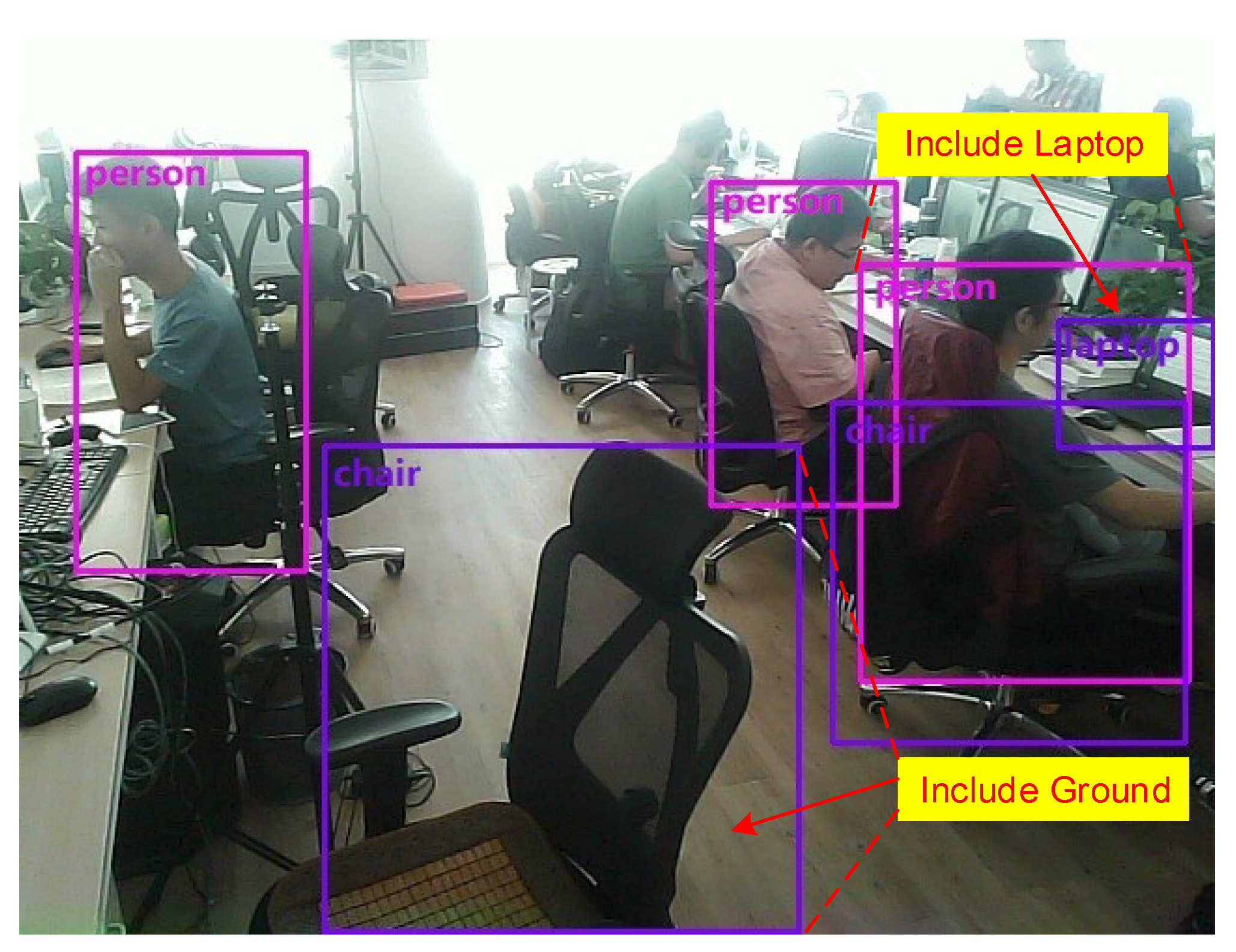
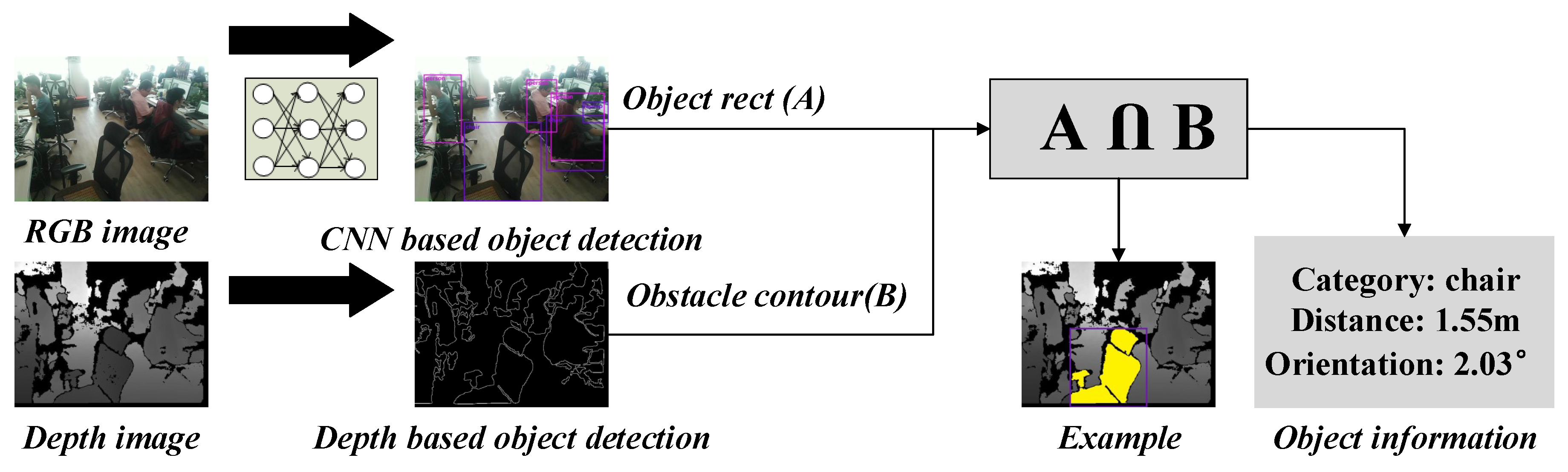
3.2.1. CNN-Based Object Detection

As the PeleeNet [42] achieves relatively better results than other architectures, such as SqueezeNet [37], Mobilenet [38], Xception [39], ShuffleNet [40], and Mobilenetv2 [41], we use PeleeNet + SSD with a carefully selected feature map to realize the object-detection task. The proposed method has two stages: offline and online. The offline process trains the PeleeNet on the MS COCO dataset, which includes 80 object categories, such as person, car, bus, and chair, that are enough for general perception. The image resolution is 640 × 640 , and the batch size is set to 64. We first train the model with the learning rate of 10 2 for 60K iterations, then continue training for 20K iterations with 10 3 and 10K iterations with 10 4 . The online process predicts the object categories by using the trained model and weights in the offline process. The online process runs on the smartphone, and achieves approximately 10 fps.
Although the CNN-based object detection can provide the object category, it still lacks the object location and orientation information, which is crucial in helping the VIP to fully perceive the environment. For example, if an object painted on the ground is detected, and the VIP only notified its category, the VIP might think there is an object blocking his/her way, resulting in an incorrect decision to avoid it. To solve this problem, we integrate a depth image-based object-detection method with the CNN-based method, which is described in the following section.

3.2.2. Depth-Based Object Detection

To obtain object location and orientation information, the object distance must be calculated. However, because the regressed rectangular box includes the detected object and might include some other objects, e.g., the chair box has many ground areas, and the person box includes the laptop object as shown in Figure 7, we cannot directly map the box to the depth image to compute the object distance by averaging the depth values within the mapped area. Instead, we first remove the detected ground area from the depth image, then extract the contours of objects, and finally merge the box with the contours, as shown in Figure 8. The detailed processing steps are stated as follows:
  • Remove the ground area from the depth image.
  • Fill the holes and perform close morphological processing to reduce the noise, isolate individual elements, and join disparate elements in the depth image.
  • Extract the external contours of the objects and compute the corresponding area.
  • If the contour area is less than a threshold S, the corresponding contour will be taken as noise; otherwise, the zero-order moment m 00 and the first-order moment m 10 , m 01 of each contour is obtained. Then the centroid c e n t e r ( x , y ) of the contour is calculated through:
    x = m 10 m 00 , y = m 01 m 00 ,
  • Based on the contour centroid and the mapped object box, the intersection (see the yellow region in Figure 8) can be obtained:
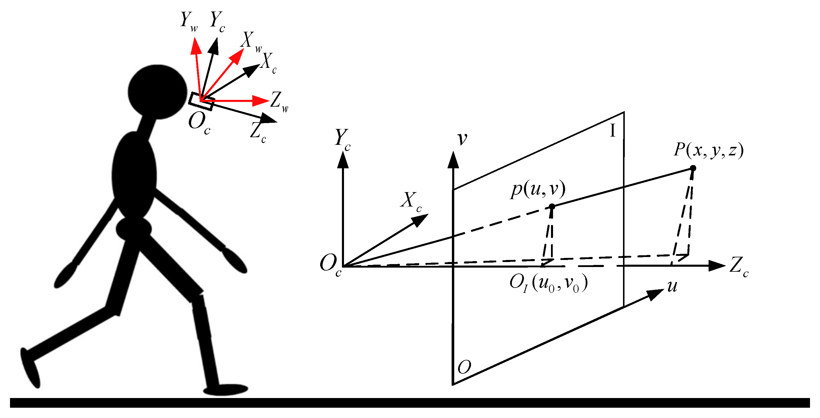
    C = A B .
  • If S C max ( S A , S B ) ( S i represents the area of region i) is greater than a threshold ζ (e.g., 0.7), it means the mapped box and the detected contour is the same object. Then the object distance z m i n is the minimum non-zero depth value within the intersection area C, and the object location and orientation information ( θ p i t c h , θ y a w , z ) relative to the user can be obtained by:
    θ p i t c h = 180 π arctan ( x u 0 f x ) θ y a w = 180 π arctan ( y v 0 f y ) z = z min ,
    where ( x , y ) is the contour centroid, and u 0 , v 0 are the camera intrinsic parameters which are the same with Equation (1).
The above algorithms, such as hole-filling, morphological processing, and moment computing, are based on the OpenCV (https://opencv.org/). The recognition system described so far provides the key surrounding information including obstacle category, location, and orientation, which will improve the perception ability of VIP while walking in an unfamiliar environment.

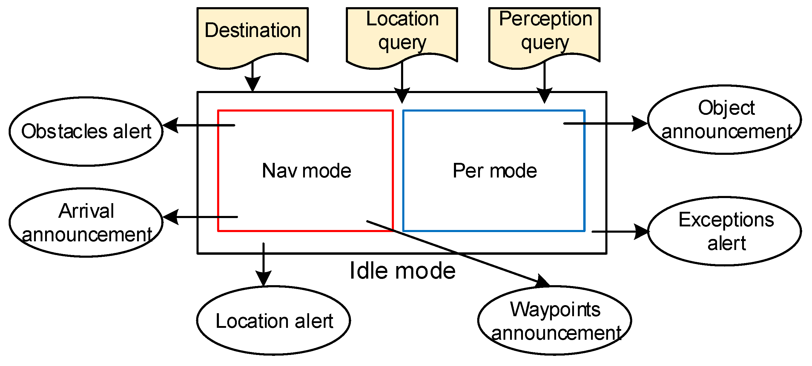
3.3. Human–Machine Interaction

The HMI is critical for good user experience. As the survey about user interface preferences in design a navigation aid [51] shows that the subjects prefer audio as the output media for navigation, and the survey made in [52] shows that the blind participants prefer tactile input, we design an audio feedback for delivering the guidance and semantic information, and a tactile input for starting the navigation and recognition system.

3.3.1. Operational Mode

The operational mode of the proposed HMI is depicted in Figure 9. The ellipses represent audio announcements or alerts, and the shaded command shapes represent user inputs. The HMI has three operational modes: idle mode (outer rectangle), navigation mode (inner red rectangle) and perception mode (inner blue rectangle). The area between outer and inner rectangle represents the application being worked in all modes.
After the system initialization and localization, the system enters the idle mode. In this mode, the user can input navigation command, query his/her location and query surrounding information. The alerts include location alerts to announce the user’s location and exception alerts (e.g., the power is below a threshold, the camera is not connected). To enter navigation mode, the user just needs to determine a destination and taps the smartphone screen once.
In navigation mode, a global cognitive waypoint path (how many turns to the destination) is provided and then a general description of this path is announced to the user, including the turning direction and moving distance. While encountering obstacles, the user is notified by the obstacle alerts. When the destination is approached, the arrival announcement works for informing the user, and the system stops the navigation of this time and enters the idle mode.
Whenever the user wants to know his/her surrounding information and whatever the system mode is, he/she just double-taps the smartphone screen and the system will enter perception mode. In perception mode, a general description of the object is announced to the user, including the object’s category, location, and orientation. When the object announcement is over, the system will return to its previous mode (idle or navigation mode).

3.3.2. Speech and Audio HMI

The system uses the TTS (https://developer.android.com/reference/android/speech/tts/TextToSpeech?hl=en) to deliver system feedback such as location awareness information, object information, system exceptions, waypoint guidance, arrival alerts, and other system instructions. Furthermore, a SpeechRecognizer (https://developer.android.com/reference/android/speech/SpeechRecognizer?hl=en) is implemented for user input, such as the navigation destination and query information. The related feedback and command information is listed in Table 2.
To decrease the cognitive load for the user, a message and command dispatcher is designed to convey the messages according to the message priority. Consequently, the system allows higher-priority messages to be played out in time to replace the current announcing message. Moreover, due to the guiding instructions having a high update frequency, we use a beeping sound instead of speech to provide the navigation information. If the walkable direction γ searched in Section 3.1.3 is not straight, i.e., the user encounters obstacles, the system will keep beeping until the user finds the right direction. In that case, the system does not directly inform the user of the walkable direction but allows the user to actively turn left or right to find the right direction. Once the beeping sound stops, the user can continue to move forward. In order to ensure the user‘s safety, we set the obstacle alert (i.e., the beeping sound) to the highest priority.

4. Experimental Results and Discussions

The proposed system is evaluated in both indoor and outdoor environments. We first test the ground segmentation performance since it plays an important role in the whole system. Then, 20 VIPs (ten of them totally blind and the others partially sighted) are recruited to test the navigation and recognition system performance in real-world scenarios, and are asked some questions to qualitatively analyze the system. We follow the protocol approved by the Bejing Fangshan District Disabled Persons’ Federation for recruitment and experiments. All the people who participated in this experiment approve that the results (including data, images, and videos) can be published with anonymity. Finally, the computational cost is measured to test the real-time performance.

4.1. Experiments on Ground Segmentation

To evaluate the proposed ground segmentation method quantitatively, we have manually labeled a representative sample of 2000 images (1000 images in indoor and outdoor, respectively) to get the ground truth. The images are captured under different light conditions in indoor environment and different weather conditions in outdoor environment, as shown in Figure 10.
We use the Intersection Over Union (IOU) (see Equation (14)) metric, which is widely used in object-detection area, to evaluate the performance of the proposed ground segmentation method.
I O U = N d e t e c t e d N g r o u n d t r u t h N d e t e c t e d N g r o u n d t r u t h ,
where N d e t e c t e d is the number of detected ground pixels, and N g r o u n d t r u t h is the number of ground truth pixels.
As shown in Figure 11, we compare the proposed method with the traditional RANSAC algorithm in different measuring distance and different IOU percentages, and the results show that the proposed method has a higher precision than RANSAC algorithm in both indoor and outdoor scenarios. In outdoor environments, the RANSAC algorithm achieves comparable precision with our proposed method. However, in indoor environments, the proposed method outperforms the RANSAC algorithm. This is because the indoor environment is more complicated than the outdoor environment, such as the interferences of the other planes (e.g., sofa and table) as shown in Figure 12. The proposed method, leveraging the ground height continuity among adjacent frames, is more robust to other plane interferences. However, due to the measuring errors of the RGB-D camera that increase with depth, the precision of ground segmentation, on the whole, decreases as distance increase. In addition, due to the inherent limitations of distance-measuring principle, the depth measurement is prone to errors in overexposure outdoors, and ground reflections indoors. As a result, some ground areas are missed or detected with mistakes as shown in Figure 13. In the future, we will combine the RGB image to solve this problem.

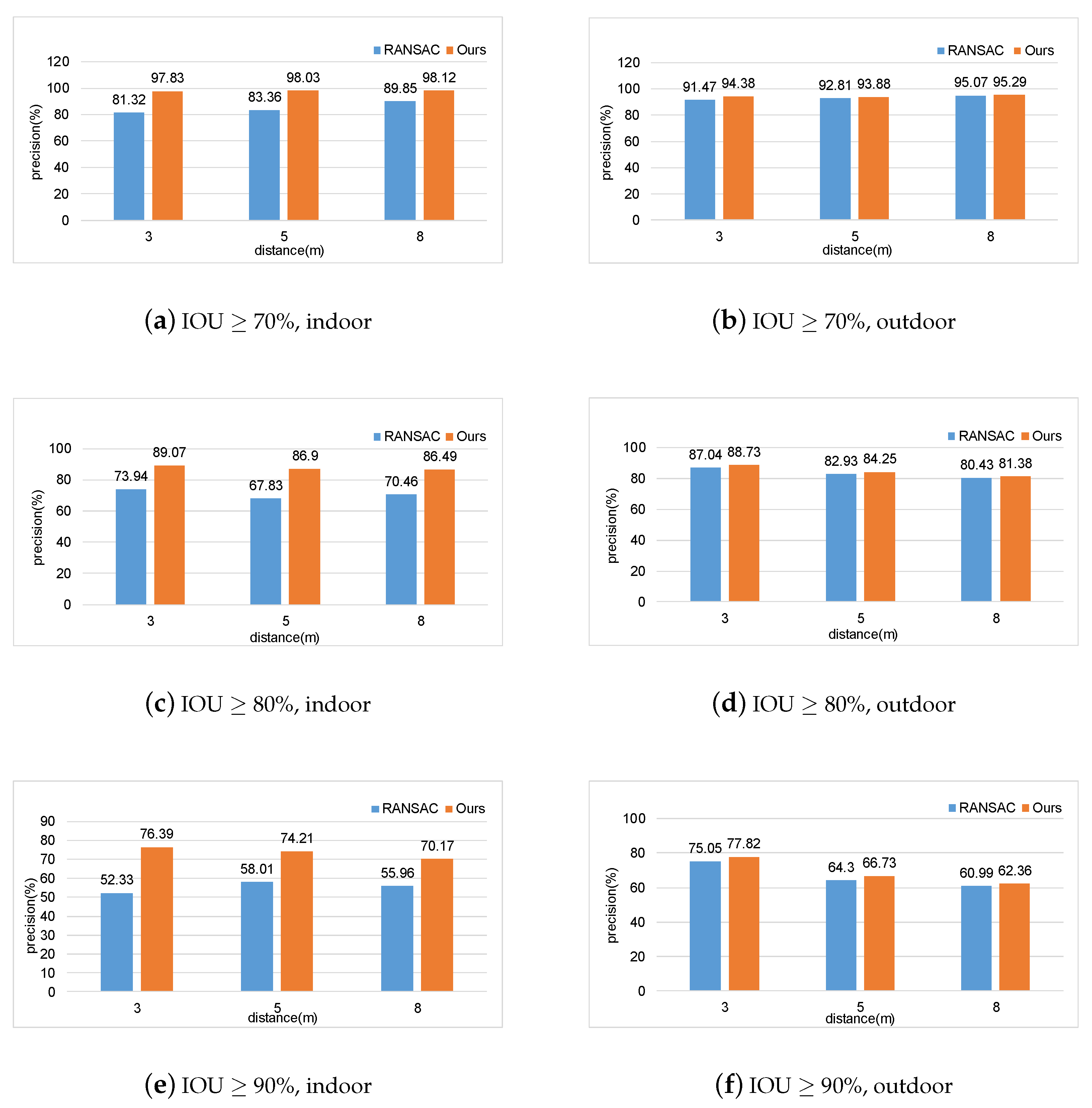
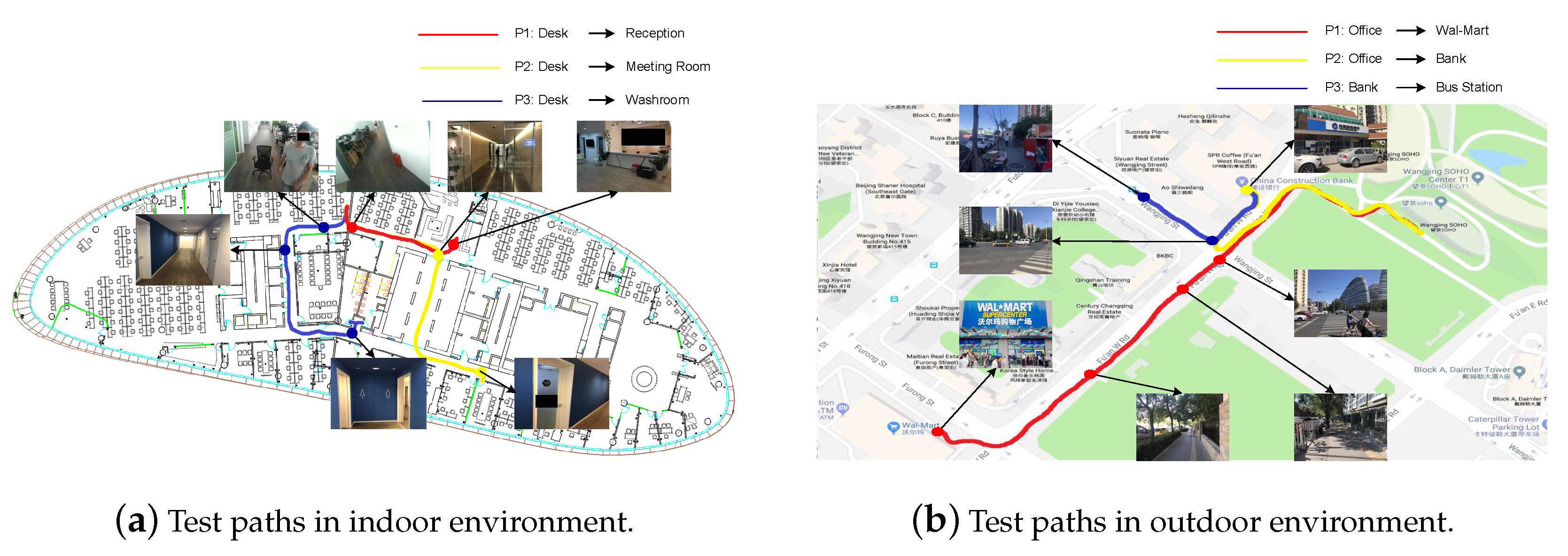
4.2. Experiments on Real-World Scenarios

We select three paths respectively in indoor and outdoor environments to evaluate the navigation system and recognition system. As shown in Figure 14, we choose an office area as the indoor testing scenarios, and simulate the scenarios that a VIP usually encounters in outdoor scenarios, such as going to a market, going to a bank, and going to a bus station. In the indoor environment, we put a fixed number of obstacles on the three paths, whereas in the outdoor environment, we cannot set up the number of obstacles but count the number of obstacles that the participants encountered when they are testing. The obstacles include static (e.g., chair, desk, and tree) and moving objects (e.g., pedestrian, car, and bicycle). Before the test, the 20 participants are trained for about 10 minutes to know how to use our system. Then they are asked to navigate following these paths with the help of either a white cane or our system. In order to compare our system with the white cane fairly, when they navigate by using the white cane, we tell them where they should go at the key locations (e.g., corners and crossroads), which serves as the global path-planning module. Then we count the average walking time and the number of collisions to evaluate the performance of our system, and the results are shown in Table 3.
From Table 3, we can see that the participants using our proposed system spend less walking time than using the white cane in both indoor and outdoor environments, demonstrating that the proposed system is able to navigate the users efficiently when they are in unfamiliar environments. Furthermore, the participants have more collisions when using the white cane, as the objects hanging in mid-air are hard to detect for the white cane (see Figure 15); whereas with our system, the participants can avoid such collisions. However, in the Path P3 of indoor environment and in the Path P2 of outdoor environment, the participants with our system still have a few collisions. This is because the small-size objects have depth values approximating to the depth of the ground, and it is hard for the proposed system to distinguish them by only relying on the depth information. Although the participants collide with these objects, such a small object does no harm to the participants. Therefore, the proposed system is verified to be secure for navigation.
To test the effect of object recognition on the blind navigation, we design some more complicated scenarios, such as the scenario where the way is blocked by two chairs (see Figure 16) and crowded with other obstacles. With only the proposed navigation system, the user cannot follow the original shortest global path to arrive the destination, but to turn back and plan a new path to the destination (the red path in Figure 16). However, if he activates the object recognition and perceives more information about surroundings, he can move the chair and find the moving direction as shown in Figure 17. As a result, the user can continue to follow the original shortest path to the destination instead of taking more detours. This shows that object recognition can promote navigation, especially in some complicated scenarios.

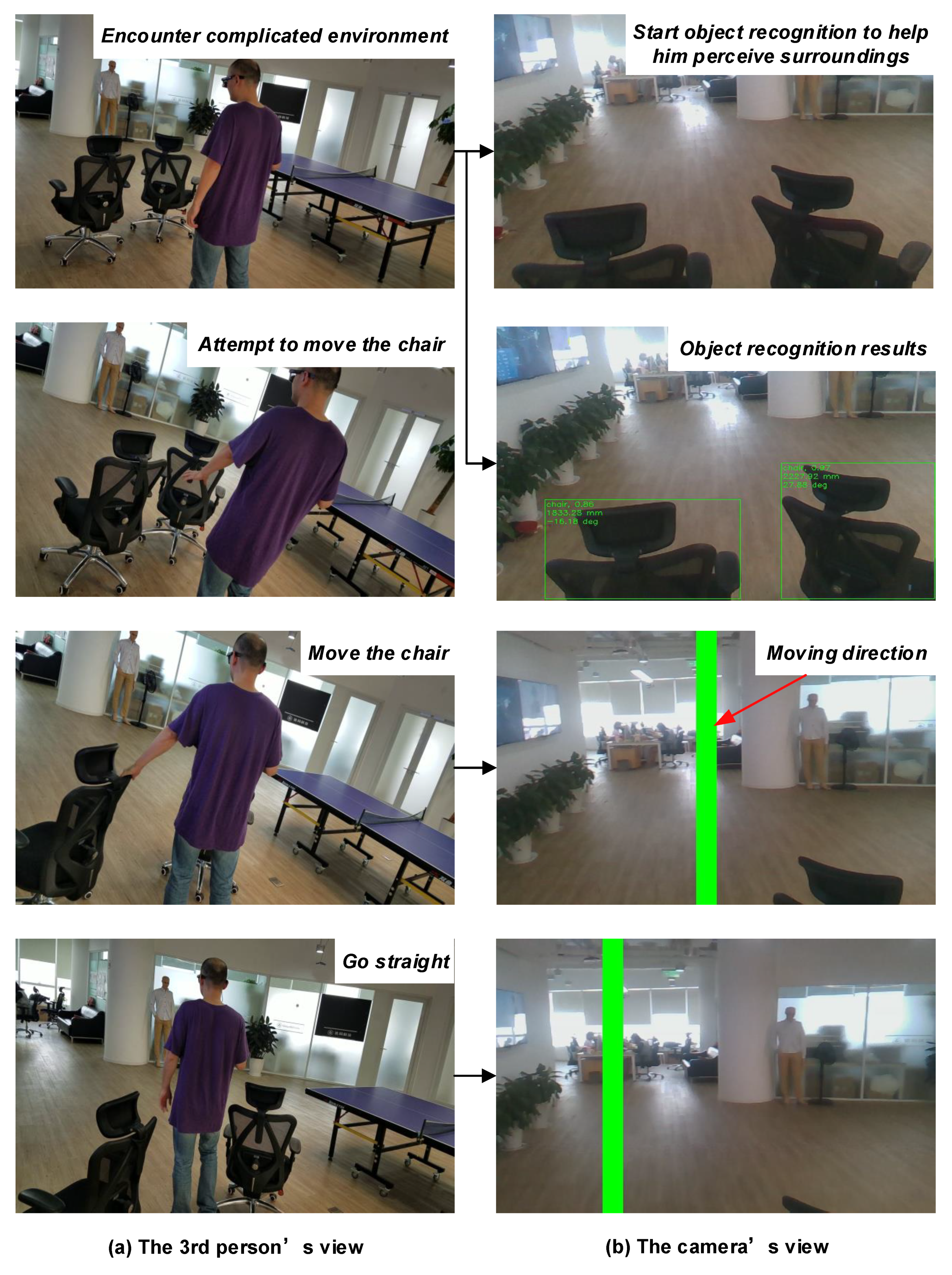
4.3. Qualitative Analysis

After the real-world test, 10 participants were asked four simple questions including whether the device was easy to wear, whether the system provided assistance to move in unfamiliar scenarios, whether the feedback is timely, and where do you think the system can be improved. The questionnaire is shown in Table 4, where all users answered that the system is useful and could guide them to the destination and help them perceive semantic surrounding information.
Regarding their detailed feelings, User 2 thinks the device is useful for avoiding the hanging obstacles, and believes that a detailed tutorial will be helpful to better use this device. User 3 thinks that the beeping sound may cause an uncomfortable feeling if using this device for a long time, and suggests using tactile feedback, such as vibration. User 4 thinks that the pair of glasses seems a little too heavy for her nose, and advises that the device is integrated in a backpack. User 6 thinks that the object recognition is very useful, and if face recognition is added, he could greet with his friends actively. User 7 thinks that the device is useful for her daily traveling, but it is still not satisfactory when she wants to move across different floors. She strongly suggests designing feedback regarding staircases. User 9 thinks that the navigation system is acceptable, which is very useful in navigating to an unfamiliar place, and the recognition capability can become more powerful, such as recognizing characters, cash, and traffic signals.

4.4. Computational Cost

All algorithms are implemented on a smartphone with Qualcomm Snapdragon 820 CPU 2.0 GHz and RAM of 4 GB. We counted the total time that each module takes to process 1000 frames and then computed the average processing time of these modules as shown in Table 5. The data acquisition, ground segmentation, moving direction search, global path planning, and object detection cost about 38.06 ms, 13.53 ms, 7.19 ms, 18.22 ms, and 114.13 ms, respectively. The indoor and outdoor localization takes about 45.36 ms and 13.06 ms, respectively. As global path-planning does not work while guiding the VIP, object detection is only activated when the user wants to know the surrounding information, and the localization runs in parallel with obstacle avoidance; the proposed system achieves a real-time performance (approximate 20 fps) on a smartphone.

5. Conclusions

Most literature on blind assistance focuses on navigation or obstacle avoidance, and some also consider object detection. However, the works that integrate both guidance and recognition capabilities into a single device still have some limitations, such as complex computation, and indoor-only application. Therefore, this paper presents a wearable device which provides real-time navigation and object-recognition assistance for VIPs in both indoor and outdoor environments.
Based on our previous work [10,11], we expand the navigation capability to realize outdoor applications by fusing GPS and IMU information. Furthermore, we use the RGB-D camera that can work in both indoor and outdoor environments to perceive the surroundings. We also propose a depth-based ground segmentation method that leverages the ground height continuity between two adjacent frames to detect the ground adaptively and robustly. On the basis of the detected ground, we search an optimal moving direction to guide the user to the desired destination. Moreover, we design a lightweight CNN-based object-recognition system to increase the environmental perception ability of the VIP, and promote the navigation system. Through a comprehensive set of experiments, the proposed system is demonstrated to be an efficient assistance for navigating VIPs.
In the future, we aim to improve the obstacle-avoidance algorithm. Specifically, the RGB image will be incorporated to detect small-size obstacles. In addition, we will continuously enhance the object-recognition capability, especially staircase detection as the participants suggested, and add tactile feedback. Moreover, it is necessary to run a larger study with VIPs to test the proposed system in different indoor (e.g., supermarket and home) and outdoor (e.g., park, community, and campus) scenarios.

Author Contributions

This work was conceptualized by J.B., who also was responsible for writing, reviewing, and editing this paper, and Z.L., who also oversaw project administration. Y.L. (Yimin Lin) designed the indoor and outdoor localization algorithm, Y.L. (Ye Li) developed the ground segmentation method, J.B. proposed the moving direction search method, and trained the object-detection network with the help of Z.L., S.L. and D.L. developed the audio feedback interface. J.B., Y.L. (Yimin Lin), Y.L. (Ye Li) and Z.L. carried out the data curation, experimental validation and formal analysis. S.L. and D.L. reviewed this paper and supervised the whole work.

Funding

This research received no external funding.

Acknowledgments

We thank the Bejing Fangshan District Disabled Persons’ Federation for helping us to recruit the participants, and thank the participants to give us the valuable advice to improve the system performance or usage. We also thank the anonymous reviewers for the insightful comments and valuable suggestions.

Conflicts of Interest

The authors declare no conflict of interest.

Abbreviations

The following abbreviations are used in this manuscript:
WHOWorld Health Organization
VIPVisually Impaired Person
RGB-DRed, Green, Blue and Depth
IMUInertial Measurement Unit
CNNConvolutional Neural Network
RANSACRANdom SAmple Consensus
GPUGraphics Processing Unit
GPRGaussian Process Regressors
ICPIterative Closest Point
GMMGaussian Mixture Model
TTSText-to-Speech
POIPoints of Interest
RCNNRecursive Convolutional Neural Network
HMIHuman–Machine Interaction
VSLAMVisual Simultaneous Localization and Mapping
IOUIntersection Over Union

References

  1. WHO. Available online: https://www.who.int/news-room/fact-sheets/detail/blindness-and-visual-impairment (accessed on 11 October 2018).
  2. Mekhalfi, M.L.; Melgani, F.; Zeggada, A.; De Natale, F.G.; Salem, M.A.M.; Khamis, A. Recovering the sight to blind people in indoor environments with smart technologies. Expert Syst. Appl. 2016, 46, 129–138. [Google Scholar] [CrossRef]
  3. Bhatlawande, S.; Mahadevappa, M.; Mukherjee, J.; Biswas, M.; Das, D.; Gupta, S. Design, development, and clinical evaluation of the electronic mobility cane for vision rehabilitation. IEEE Trans. Neural Syst. Rehabil. Eng. 2014, 22, 1148–1159. [Google Scholar] [CrossRef]
  4. Islam, M.M.; Sadi, M.S.; Zamli, K.Z.; Ahmed, M.M. Developing walking assistants for visually impaired people: A review. IEEE Sens. J. 2019, 19, 2814–2828. [Google Scholar] [CrossRef]
  5. Sivan, S.; Darsan, G. Computer vision based assistive technology for blind and visually impaired people. In Proceedings of the International Conference on Computing Communication and Networking Technologies, Dallas, TX, USA, 6–8 July 2016. [Google Scholar]
  6. Fei, Z.; Yang, E.; Hu, H.; Zhou, H. Review of machine vision-based electronic travel aids. In Proceedings of the 2017 23rd International Conference on Automation and Computing (ICAC), Huddersfield, UK, 7–8 September 2017; pp. 1–7. [Google Scholar]
  7. Jafri, R.; Ali, S.A.; Arabnia, H.R.; Fatima, S. Computer vision-based object recognition for the visually impaired in an indoors environment: A survey. Vis. Comput. 2014, 30, 1197–1222. [Google Scholar] [CrossRef]
  8. Tian, Y. RGB-D sensor-based computer vision assistive technology for visually impaired persons. In Computer Vision and Machine Learning with RGB-D Sensors; Shao, L., Han, J., Kohli, P., Zhang, Z., Eds.; Springer: Cham, Switzerland, 2014; pp. 173–194. [Google Scholar]
  9. Aladrén, A.; López-Nicolás, G.; Puig, L.; Guerrero, J.J. Navigation assistance for the visually impaired using RGB-D sensor with range expansion. IEEE Syst. J. 2016, 10, 922–932. [Google Scholar] [CrossRef]
  10. Bai, J.; Lian, S.; Liu, Z.; Wang, K.; Liu, D. Virtual-blind-road following-based wearable navigation device for blind people. IEEE Trans. Consum. Electron. 2018, 64, 136–143. [Google Scholar] [CrossRef]
  11. Bai, J.; Lian, S.; Liu, Z.; Wang, K.; Liu, D. Smart guiding glasses for visually impaired people in indoor environment. IEEE Trans. Consum. Electron. 2017, 63, 258–266. [Google Scholar] [CrossRef]
  12. Söveny, B.; Kovács, G.; Kardkovács, Z.T. Blind guide—A virtual eye for guiding indoor and outdoor movement. In Proceedings of the 2014 5th IEEE Conference on Cognitive Infocommunications (CogInfoCom), Vietri sul Mare, Italy, 5–7 November 2014; pp. 343–347. [Google Scholar]
  13. Kanwal, N.; Bostanci, E.; Currie, K.; Clark, A.F. A navigation system for the visually impaired: A fusion of vision and depth sensor. Appl. Bionics Biomech. 2015, 2015, 479857. [Google Scholar] [CrossRef]
  14. Kang, M.C.; Chae, S.H.; Sun, J.Y.; Yoo, J.W.; Ko, S.J. A novel obstacle detection method based on deformable grid for the visually impaired. IEEE Trans. Consum. Electron. 2015, 61, 376–383. [Google Scholar] [CrossRef]
  15. Kang, M.C.; Chae, S.H.; Sun, J.Y.; Lee, S.H.; Ko, S.J. An enhanced obstacle avoidance method for the visually impaired using deformable grid. IEEE Trans. Consum. Electron. 2017, 63, 169–177. [Google Scholar] [CrossRef]
  16. Yang, K.; Wang, K.; Hu, W.; Bai, J. Expanding the detection of traversable area with RealSense for the visually impaired. Sensors 2016, 16, 1954. [Google Scholar] [CrossRef]
  17. Yang, K.; Wang, K.; Bergasa, L.M.; Romera, E.; Hu, W.; Sun, D.; Sun, J.; Cheng, R.; Chen, T.; López, E. Unifying terrain awareness for the visually impaired through real-time semantic segmentation. Sensors 2018, 18, 1506. [Google Scholar] [CrossRef]
  18. Ye, C.; Hong, S.; Qian, X.; Wu, W. Co-robotic cane: A new robotic navigation aid for the visually impaired. IEEE Syst. Man Cybern. Mag. 2016, 2, 33–42. [Google Scholar] [CrossRef]
  19. Zhang, H.; Ye, C. An indoor wayfinding system based on geometric features aided graph SLAM for the visually impaired. IEEE Trans. Neural Syst. Rehabil. Eng. 2017, 25, 1592–1604. [Google Scholar] [CrossRef]
  20. Ye, C.; Qian, X. 3-D object recognition of a robotic navigation aid for the visually impaired. IEEE Trans. Neural Syst. Rehabil. Eng. 2018, 26, 441–450. [Google Scholar] [CrossRef]
  21. Ţepelea, L.; Gavriluţ, I.; Gacsádi, A. Smartphone application to assist visually impaired people. In Proceedings of the 2017 14th International Conference on Engineering of Modern Electric Systems (EMES), Oradea, Romania, 1–2 June 2017; pp. 228–231. [Google Scholar]
  22. Vera, D.; Marcillo, D.; Pereira, A. Blind guide: Anytime, anywhere solution for guiding blind people. In World Conference on Information Systems and Technologies; Springer: Cham, Switerland, 2017; pp. 353–363. [Google Scholar]
  23. Wang, H.C.; Katzschmann, R.K.; Teng, S.; Araki, B.; Giarré, L.; Rus, D. Enabling independent navigation for visually impaired people through a wearable vision-based feedback system. In Proceedings of the 2017 IEEE International Conference on Robotics and Automation (ICRA), Singapore, 29 May–3 June 2017; pp. 6533–6540. [Google Scholar]
  24. Mancini, A.; Frontoni, E.; Zingaretti, P. Mechatronic system to help visually impaired users during walking and running. IEEE Trans. Intell. Transp. Syst. 2018, 19, 649–660. [Google Scholar] [CrossRef]
  25. Eckert, M.; Blex, M.; Friedrich, C.M. Object detection featuring 3D audio localization for Microsoft HoloLens. In Proceedings of the 11th International Joint Conference on Biomedical Engineering Systems and Technologies, Funchal, Portugal, 19–21 January 2018; Volume 5, pp. 555–561. [Google Scholar]
  26. Long, N.; Wang, K.; Cheng, R.; Yang, K.; Hu, W.; Bai, J. Assisting the visually impaired: Multitarget warning through millimeter wave radar and RGB-depth sensors. J. Electron. Image 2019, 28, 013028. [Google Scholar] [CrossRef]
  27. Li, B.; Munoz, J.P.; Rong, X.; Chen, Q.; Xiao, J.; Tian, Y.; Arditi, A.; Yousuf, M. Vision-based mobile indoor assistive navigation aid for blind people. IEEE Trans. Mob. Comput. 2019, 18, 702–714. [Google Scholar] [CrossRef]
  28. Tapu, R.; Mocanu, B.; Bursuc, A.; Zaharia, T. A smartphone-based obstacle detection and classification system for assisting visually impaired people. In Proceedings of the 2013 IEEE ICCV Workshops, Sydney, Australia, 2–8 December 2013; pp. 444–451. [Google Scholar]
  29. Krizhevsky, A.; Sutskever, I.; Hinton, G. ImageNet classification with deep convolutional neural networks. In Proceedings of the 25th International Conference on Neural Information Processing Systems, Lake Tahoe, NV, USA, 3–6 December 2012; pp. 1097–1105. [Google Scholar]
  30. Russakovsky, O.; Deng, J.; Su, H.; Krause, J.; Satheesh, S.; Ma, S.; Huang, Z.; Karpathy, A.; Khosla, A.; Bernstein, M.; et al. Imagenet large scale visual recognition challenge. IJCV 2015, 115, 211–252. [Google Scholar] [CrossRef]
  31. Tapu, R.; Mocanu, B.; Zaharia, T. DEEP-SEE: Joint object detection, tracking and recognition with application to visually impaired navigational assistance. Sensors 2017, 17, 2473. [Google Scholar] [CrossRef]
  32. Lin, B.; Lee, C.; Chiang, P. Simple smartphone-based guiding system for visually impaired people. Sensors 2017, 17, 1371. [Google Scholar] [CrossRef]
  33. Parikh, N.; Shah, I.; Vahora, S. Android smartphone based visual object recognition for visually impaired using deep learning. In Proceedings of the 2018 International Conference on Communication and Signal Processing (ICCSP), Chennai, India, 3–5 April 2018; pp. 0420–0425. [Google Scholar]
  34. Bashiri, F.S.; LaRose, E.; Badger, J.C.; D’Souza, R.M.; Yu, Z.; Peissig, P. Object detection to assist visually impaired people: A deep neural network adventure. In International Symposium on Visual Computing; Springer: Cham, Switerland, 2018; pp. 500–510. [Google Scholar]
  35. Trabelsi, R.; Jabri, I.; Melgani, F.; Smach, F.; Conci, N.; Bouallegue, A. Indoor object recognition in rgbd images with complex-valued neural networks for visually-impaired people. Neurocomputing 2019, 330, 94–103. [Google Scholar] [CrossRef]
  36. Kaur, B.; Bhattacharya, J. A scene perception system for visually impaired based on object detection and classification using multi-modal DCNN. arXiv 2018, arXiv:1805.08798. [Google Scholar]
  37. Forrest, N.I.; Song, H.; Matthew, W.M.; Khalid, A.; William, J.D.; Kurt, K. SqueezeNet: AlexNet-level accuracy with 50x fewer parameters and <0.5MB model size. arXiv 2016, arXiv:1602.07360. [Google Scholar]
  38. Howard, A.G.; Zhu, M.; Chen, B.; Kalenichenko, D.; Wang, W.; Weyand, T.; Andreetto, M.; Adam, H. Mobilenets: Efficient convolutional neural networks for mobile vision applications. arXiv 2017, arXiv:1704.04861. [Google Scholar]
  39. Chollet, F. Xception: Deep learning with depthwise separable convolutions. In Proceedings of the IEEE Conference on Computer Vision and Pattern Recognition, Honolulu, HI, USA, 22–25 July 2017; pp. 1800–1807. [Google Scholar]
  40. Zhang, X.; Zhou, X.; Lin, M.; Sun, J. ShuffleNet: An extremely efficient convolutional neural network for mobile devices. In Proceedings of the IEEE Conference on Computer Vision and Pattern Recognition, Salt Lake City, UT, USA, 18–22 June 2018; pp. 6848–6856. [Google Scholar]
  41. Sandler, M.; Howard, A.; Zhu, M.; Zhmoginov, A.; Chen, L. Mobilenetv2: Inverted residuals and linear bottlenecks. In Proceedings of the IEEE Conference on Computer Vision and Pattern Recognition, Salt Lake City, UT, USA, 18–22 June 2018; pp. 4510–4520. [Google Scholar]
  42. Wang, R.J.; Li, X.; Ling, C.X. Pelee: A real-time object detection system on mobile devices. In Proceedings of the Advances in Neural Information Processing Systems, NIPS 2018, Montréal, QC, Canada, 2–8 December 2018; pp. 1963–1972. [Google Scholar]
  43. Mur-Artal, R.; Tardos, J.D. Orb-slam2: An open-source slam system for monocular, stereo, and rgb-d cameras. IEEE Trans. Robot. 2017, 33, 1255–1262. [Google Scholar] [CrossRef]
  44. Tong, Q.; Peiliang, L.; Shaojie, S. Vins-mono: A robust and versatile monocular visual-inertial state estimator. IEEE Trans. Robot. 2018, 34, 1004–1020. [Google Scholar]
  45. QQMAP. Available online: https://lbs.qq.com/android_v1/index.html (accessed on 25 March 2019).
  46. Caron, F.; Duflos, E.; Pomorski, D.; Vanheeghe, P. GPS/IMU data fusion using multisensor kalman filtering: Introduction of contextual aspects. Inf. Fusion 2006, 7, 221–230. [Google Scholar] [CrossRef]
  47. Otsu, N. A threshold selection method from gray-level histograms. IEEE Trans. Syst. Man Cybern. 1979, 9, 62–66. [Google Scholar] [CrossRef]
  48. Fischler, M.A.; Bolles, R.C. Random sample consensus: A paradigm for model fitting with applications to image analysis and automated cartography. Commun. ACM 1981, 24, 381–395. [Google Scholar] [CrossRef]
  49. Alkhanifer, A.; Ludi, S. Towards a situation awareness design to improve visually impaired orientation in unfamiliar buildings: Requirements elicitation study. In Proceedings of the IEEE 22nd International Requirements Engineering Conference (RE), Karlskrona, Sweden, 25–29 August 2014; pp. 23–32. [Google Scholar]
  50. Endsley, M.R. Toward a theory of situation awareness in dynamic systems. Hum. Factors 1995, 37, 32–64. [Google Scholar] [CrossRef]
  51. Arditi, A.; Tian, Y. User interface preferences in the design of a camera-based navigation and wayfinding aid. J. Vis. Impair. Blind. 2013, 107, 118–129. [Google Scholar] [CrossRef]
  52. Golledge, R.G.; Marston, J.R.; Loomis, J.M.; Klatzky, R.L. Stated preferences for components of a personal guidance system for nonvisual navigation. J. Vis. Impair. Blind. 2004, 98, 135–147. [Google Scholar] [CrossRef]
Figure 1. The prototype of the proposed wearable assistive device.
Electronics 08 00697 g001
Figure 2. System overview: PerMsg-perception message, NavMsg-navigation message.
Electronics 08 00697 g002
Figure 3. Examples of planned path: (a) A global path from bar to room3311 is represented by the red arrow. (b) A global path from an office building to a 7-eleven is depicted by the dashed line.
Electronics 08 00697 g003
Figure 4. Coordinate system transformation.
Electronics 08 00697 g004
Figure 5. Ground fitting.
Electronics 08 00697 g005
Figure 6. Point cloud that projects on the plane X w O Z w .
Electronics 08 00697 g006
Figure 7. Example of CNN-based object detection.
Electronics 08 00697 g007
Figure 8. 2.5-D object detection (the yellow region (i.e., C in Equation (12))).
Electronics 08 00697 g008
Figure 9. HMI operational mode.
Electronics 08 00697 g009
Figure 10. Labeled samples of the ground in indoor and outdoor environment. (a) RGB image, (b) depth image, (c) ground truth of ground segmentation (the yellow region is the ground truth of the ground). (iiii) indoor environment, (ivviii) outdoor environment. (i) floor with reflections of sunlight, (ii) floor under normal light, (iii) floor with reflections of light, (iv) ground under normal sunlight, (v) ground under strong sunlight, (vi) ground after raining, (vii) ground before sunset, (viii) ground at night.
Electronics 08 00697 g010
Figure 11. Precision of ground segmentation in different measuring distance and different IOU.
Electronics 08 00697 g011
Figure 12. Samples of ground segmentation in the indoor environment. (a) RGB image, (b) the ground (the yellow region) detected by RANSAC algorithm, (c) the ground (the yellow region) detected by the proposed algorithm, (d) the ground truth (the yellow region).
Electronics 08 00697 g012
Figure 13. Errors of ground segmentation. (a) RGB image, (b) depth image, (c) the ground (the yellow region) detected by the proposed algorithm. The images of the first row show the outdoor scenario of overexposure where the proposed ground segmentation method failed to detect the ground. The images in the second row show the indoor scenario with ground reflection, where some areas are missed by the proposed method.
Electronics 08 00697 g013
Figure 14. Test paths.
Electronics 08 00697 g014
Figure 15. Collisions when the VIP use a white cane.
Electronics 08 00697 g015
Figure 16. Test scenario of object recognition to improve the navigation.
Electronics 08 00697 g016
Figure 17. Example of object recognition to promote the navigation.
Electronics 08 00697 g017
Table 1. Summary of vision-based assistive systems for VIP.
WorksYearSensorsFeedbackIndoor/outdoorWeightCostCapabilitiesLimitations
LocalizationObstacle AvoidanceObject Detection/Recognition
Söveny et al. [12]2014Two RGB camerasAudioBothLightLow-YesYesGround texture changes or other large plane such as wall in indoor scenarios may cause errors of free path detection.
Kanwal et al. [13]2015RGB-D cameraAudioBothBulkyLow-Yes-The system has no recognition capability and the obstacle detection performance degrades severely under strong sunlight.
Kang et al. [14,15]2015, 2017RGB cameraStereophonicBothLightHigh-Yes-The system cannot detect obstacles that are closed to non-textured regions such as a door or a wall.
Yang et al. [16,17]2016, 2018RGB-D cameraStereophonicBothLightHigh-YesYesThe system needs GPU to accelerate the semantic segmentation and detects obstacles only in a short range.
Mekhalfi et al. [2]2016RGB-D camera, IMU and laser sensorSpeechIndoorBulkyHigh-YesYesThe system requires the prior information about indoor environment to train the GPR, which limits its universal application in other scenarios.
Aladrén et al. [9]2016RGB-D cameraSpeech and stereo beepsIndoorLightHigh-Yes-The algorithm is complicated and only operates in indoor environment.
Ye et al. [18,19,20]2016, 2017RGB and IR cameraSpeechIndoorBulkyHighYesYesYesThe navigation and recognition systems perform separately.
Tepelea et al. [21]2017RGB camera, MEMS and ultrasonic sensorsAudioBothLightLowYesYes-The system is not tested in buildings and outdoor environment to find the optimum obstacle detection distance.
Vera et al. [22]2017RGB camera and ultrasonic sensorsAudioBothBulkyLow-YesYesThe system can only works in the scene with internet access and the recognition works well only with good light conditions.
Wang et al. [23]2017Depth cameraVibrationIndoorLightLow-YesYesThe system applies to only indoor environment and recognizes only some common objects in engineered indoor scenes, such as tables, chairs, and loungers.
Mancini et al. [24]2018RGB cameraVibrationOutdoorLightHigh--YesThe system is not suitable in crowded scenarios due to its weak obstacle-avoidance capability.
Eckert et al. [25]2018RGB-D camera and IMU sensorsAudioIndoorLightHigh--YesThe system has low recognition accuracies on small objects and needs network connection to provide the recognition service, which limits its mobility.
Long et al. [26]2019RGB-D camera and MMW radarStereophonicBothBulkyHigh-Yes-The prototype still runs on a PC, which is not portable for navigation application.
Li et al. [27]2019RGB-D cameraAudioIndoorLightHighYesYes-The semantic map needs annotation functionality of adding POI, which is not easily accessible for VIP.
Our previous works [10,11]2017, 2018RGB camera and ultrasonic sensorsAudioIndoorLightLowYesYes-The system has no recognition capability and only works in indoor environment.
Not mentioned: -.
Table 2. Speech of the system.
CategorySpeechDescription
User’s commands“Go to” + destinationThe user tells the system to guide him/her to the destinations, such as toilet, Room3301, supermarket
“Where am I”The user queries his/her current location.
System instructions“Will you start navigation to” + destinationAsk the user to make sure the destination is his/her desired one.
“You are in the” + current location.Tell the user his/her current location, such as hall, XXX road.
“There is a” + an object + distance + “meters ahead of your” + orientationInform the user about the perception information, including objects category location, and orientation. For example, “There is a chair one point eight meters ahead of your left side two degree.”
“Walk” + distance + ”meters then take a” + turn direction + “Walk” + ...+ “arrive at the destination”Allow the user to have a holistic cognition about the whole path. For example, “Walk 30 m then take a left, then walk 20 m then take a right, then walk ten meters and then arrive at the destination.”
“The destination is arrived, the navigation is over.”Inform the user that he/she arrives at the destination.
System exceptions“The camera is not connected.” “The IMU is not connected” “The power is lower than ten percent”Alert the user about the status of the key hardware components.
Table 3. Results of navigation with Cane and our assistance.
ScenarioPathLength (m)ObstaclesAverage Time (s)Total Collisions
OursCaneOursCane
IndoorP1 (Desk→Reception)∼213 (avg)60.861.500
P2 (Desk→Meeting Room)∼528 (avg)172.3183.2032
P3 (Desk→Washroom)∼ 305 (avg)101.1108.3322
OutdoorP1 (Office→Wal-Mart)∼86081 (sum)2157.52204.205
P2 (Office→Bank)∼45074 (sum)1112.31208.2520
P3 (Bank→Bus Station)∼19057 (sum)485.1502.3012
avg: average number, sum: total number.
Table 4. The questionnaire.
UsersTotally Blind or Partially SightedEasy to Wear?Useful?Feedback in Time?Advice for Future Improvement
User1Partially sightedYesYesYes
User2Partially sightedYesYesYesProvide a detailed tutorial
User3Totally blindYesYesYesAdd tactile feedback
User4Partially sightedNoYesYesDesign the device in a backpack
User5Partially sightedYesYesYes
User6Totally blindYesYesYesAdd face recognition
User7Totally blindYesYesYesFeedback about staircases
User8Partially sightedYesYesYes
User9Totally blindYesYesYesAdd character recognition, cash recognition
User10Partially sightedYesYesYes
Table 5. Computational cost of the main modules.
Processing StepAverage Time (ms)
Data acquisition38.06
Ground segmentation13.53
Moving direction search7.19
Global path planning18.22
Indoor localization45.36
Outdoor localization13.08
Object detection114.13

