Article

A Compact Crossed Inverted-V Antenna with a Common Reflector for Polarization Diversity in the IoT

School of Electrical and Electronics Engineering, Chung-Ang University, 84 Heukseok-ro, Dongjak-gu, Seoul 06974, Korea
*
Author to whom correspondence should be addressed.
Electronics 2019, 8(6), 637; https://doi.org/10.3390/electronics8060637
Submission received: 3 May 2019 / Revised: 3 June 2019 / Accepted: 3 June 2019 / Published: 6 June 2019
(This article belongs to the Special Issue IoT in 5G)

Abstract

:
This article presented a compact and high gain antenna with reconfigurable polarization based on two inverted-V dipoles fabricated in a crossed configuration, and with a common planar reflector. The proposed antenna could generate four different types of polarizations, such as vertical polarization (VP), horizontal polarization (HP), right-hand circular polarization (RHCP), and left-hand circular polarization (LHCP). A pair of inverted-V dipoles drove the polarization diversity, where each dipole had an integrated matching circuit and a microstrip balun. Using a crossed inverted-V configuration with a ground plane as the common reflector, we could achieve compactness in size, high directivity, and a wider beamwidth than a normal dipole antenna. To verify the performance of the proposed antenna, we fabricated a sub-6GHz antenna with a Taconic TLX-9 substrate, which had a relative permittivity of 2.5. The proposed antenna showed a measured 10-dB impedance bandwidth of 752 MHz (5.376 GHz to 6.128 GHz). The peak gains for the VP, HP, RHCP and LHCP operations at 5.8 GHz were about 5.2 dBi, 4.61 dBi, 5.25 dBic, and 5.51 dBic, respectively. In addition, the half-power beamwidth (HPBW) for all the polarizations were greater than 78° in the operation band.

1. Introduction

Since South Korean carriers have officially launched the world’s first commercial fifth generation (5G) service, the demand for high speed, low latency, large capacity, and massive connectivity in communication has grown more rapidly [1,2,3]. Moreover, given the rise of 5G communication, the demand for extended or new applications has accelerated, are more intensive research is required on the Internet of Things (IoT), specifically on devices that converge with the 5G network. Thus, in order to deploy successful and reliable 5G services, improvements are necessary in the 5G IoT device technologies. Although there is a broad spectrum for advanced research in the 5G IoT, the challenges in antenna technology are a primary concern. Owing to increased device connectivity in the 5G environment, simultaneous multi-device communication is unavoidable and, therefore, high electromagnetic (EM) interferences may cause a significant degradation in the device performances [4,5,6,7]. To facilitate multi-device communication with a reliable interference rejection, an antenna or antennas supporting polarization diversity are required. Especially, all types of polarizations, including horizontal polarization (HP), vertical polarization (VP), right-hand circular polarization (RHCP), and left-hand polarization (LHCP) are required to achieve the maximum spectral efficiency [8,9,10,11,12,13,14,15]. Figure 1 shows the conceptual diagram for the 5G IoT devices or sensors possessing a limited polarization and polarization diversity, as proposed in this article. As shown in Figure 1a, if multiple devices carrying various information are connected and simultaneously communicating with other devices, then signal interferences from neighboring devices cannot be avoided. However, if we transmit and receive various information through different polarizations, as shown in Figure 1b, the spectral channels can be isolated, thereby achieving greater immunity to interferences.
To provide polarization diversity, it is possible to adapt and use multiple antennas with different types of fixed polarizations, although the increase in overall size is not preferable. Since most of the modern antenna technology needs to support array architectures, a single radiation antenna by itself should also be as compact as possible. However, due to the trade-off relationship between the antenna size and radiation gain characteristics, an efficient technique to achieve high directivity whilst keeping the antenna size as compact as possible should be investigated. Additionally, the antenna characteristics at near-6 GHz changes significantly from the same antenna architecture operating below 3 GHz, citing a stronger coupling effect for compact designs. Thus, effective researches are also required on near-6 GHz compact antenna structures for IoT applications. There have been previous researches to realize the antennas with various polarization characteristics [8,9,10,11,12,13,14,15,16,17,18,19]. Some of the previous studies showed antennas with dual- or quadri-polarizations [8,9,12,15], but they suffered from low gain, large size, complicated air-bridge implementation, or large gain variation in the different polarization modes. Moreover, some antennas used crossed-dipole structures to drive circular polarizations [13,14,16,17,19]. However, the antennas also had drawbacks via the large number of PIN diode switches, only single or dual polarizations, or the requirement for conducting-walls. Other types of researches showed reconfigurable radiation patterns, although multiple polarizations were not supported [20,21,22]. In addition, several other researches showed reconfigurable polarizations based on a reconfigurable feed network, but a large number of PIN diode switches, large antenna size, or limited number of polarization types remained unsolved [23,24,25,26,27]. Moreover, there are few antennas in a crossed configuration satisfying near-6 GHz realization, compactness in volume, and reconfigurability for all polarization types. Therefore, in this article, we proposed a new compact antenna based on a crossed inverted-V structure, with a ground plane as the common reflector at 5.8 GHz. The proposed structure can generate four different types of polarizations (HP, VP, RHCP, and LHCP), and it can provide high directivities for all polarizations, despite its compact size. That is, for the first time, using the proposed structure, we verified the advanced qualifications, including the compactness in volume, high gain compared to a regular dipole, quad-polarizations, and the practical performance of the crossed structure above 5 GHz. In Section 2, we discuss the analysis for antenna design, including the feed network and matching circuit. Then, in Section 3, we presented the simulated and measured results at the center frequency of 5.8 GHz to verify the performance of the proposed work at sub-6 GHz IoT applications. Lastly, we drew our conclusion in Section 4.

2. Antenna Design

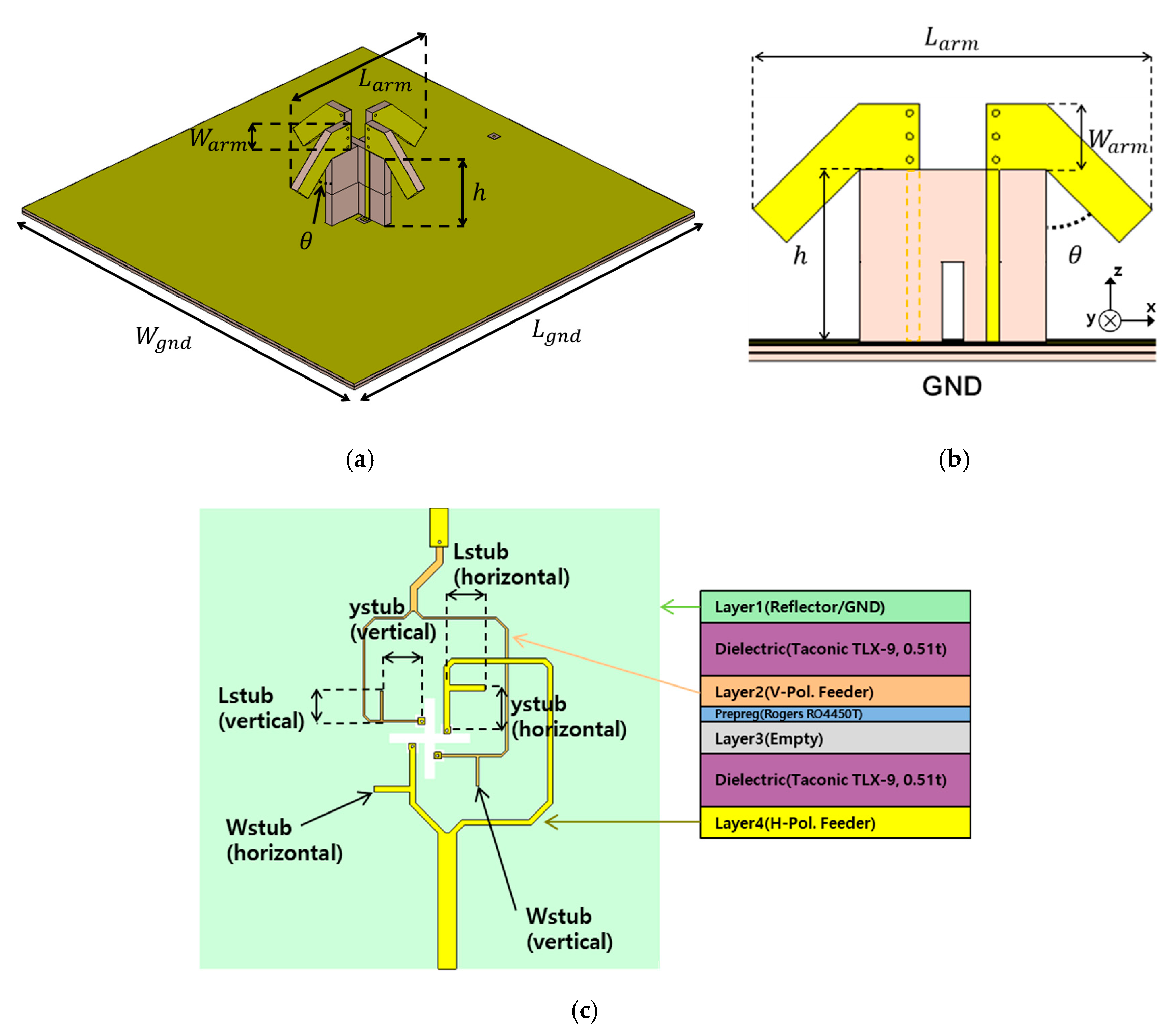
Figure 2a shows the proposed antenna with a pair of inverted-V dipoles and a ground plane as the common reflector. Figure 2b shows a single inverted-V dipole and total two inverted-V dipoles, designed in a crossed configuration for the proposed architecture. Figure 2c shows the integrated feed network and the layer information for the proposed architecture. The feed network was based on a microstrip line balun with tuning stubs, which considered a strong coupling due to the tightly crossed configuration. Thus, one inverted-V dipole could generate a HP and the other inverted-V dipole could generate a VP when they were individually excited. In addition, when both the inverted-V dipoles were simultaneously excited with a 90° phase difference, the RHCP or LHCP could be generated depending on the 90° phase lead or the lag relationship between the two inverted-V dipoles. Unlike a normal inverted-V configuration, we placed the ground reflector below the crossed inverted-V to make a radiation pattern towards the broadside with a high directivity.
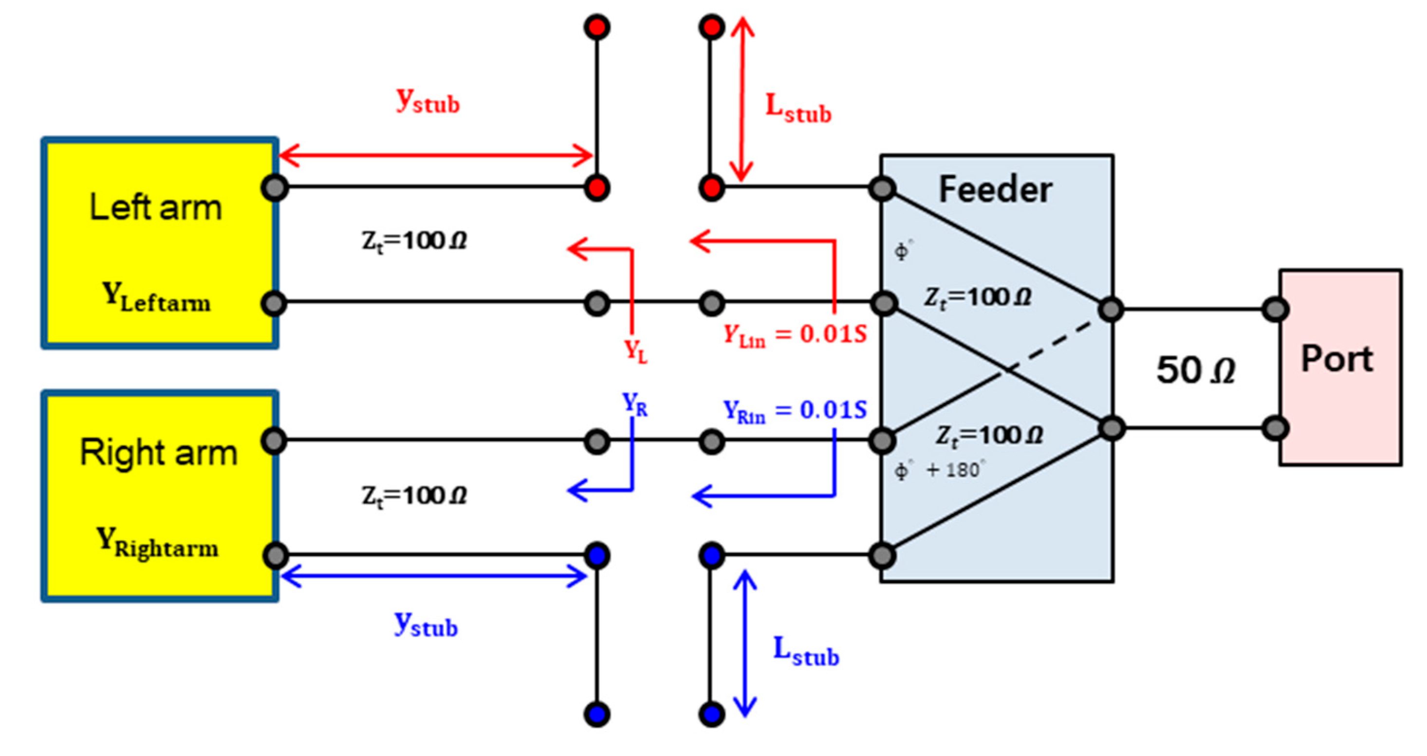
As shown in Figure 2c, we used a 4-layer feed network including a reflector plane to drive the polarization diversity. We integrated one feed network on the second layer for the VP inverted-V dipole and the other feed network was integrated on the bottom layer (layer-4) for the HP inverted-V dipole. Additionally, the third layer was only inserted for rigidity and implementation purposes. Each feed network consisted of two 100 Ω lines with a phase difference of 180°, and it was matched to a 50 Ω input impedance as shown in Figure 3. The admittances of the right and left arms of the feed network can be expressed by
y R i g h t a r m = y L e f t a r m = G a r m + j B a r m
where Garm and jBarm denote the conductance and susceptance seen at each arm, respectively. Owing to the symmetric condition, the right and left arms of the feed network had an identical admittance. Using transmission lines, the conductance (or real value) of the input admittance looking into the end of transmission line could be transformed to 0.01 S with susceptance as follows.
y R = y L = 0.01 + j B
Then, an additional microwave stub could be used to eliminate the remaining susceptance of the input admittance. After transforming the input admittance to 0.01 S (i.e., impedance of 100 Ω), each line of the feed network could be connected to each arm of the inverted-V dipole. However, due to the strong coupling between the two crossed inverted-V dipoles, the impedance matching circuit needed to be further fine-tuned after realization.
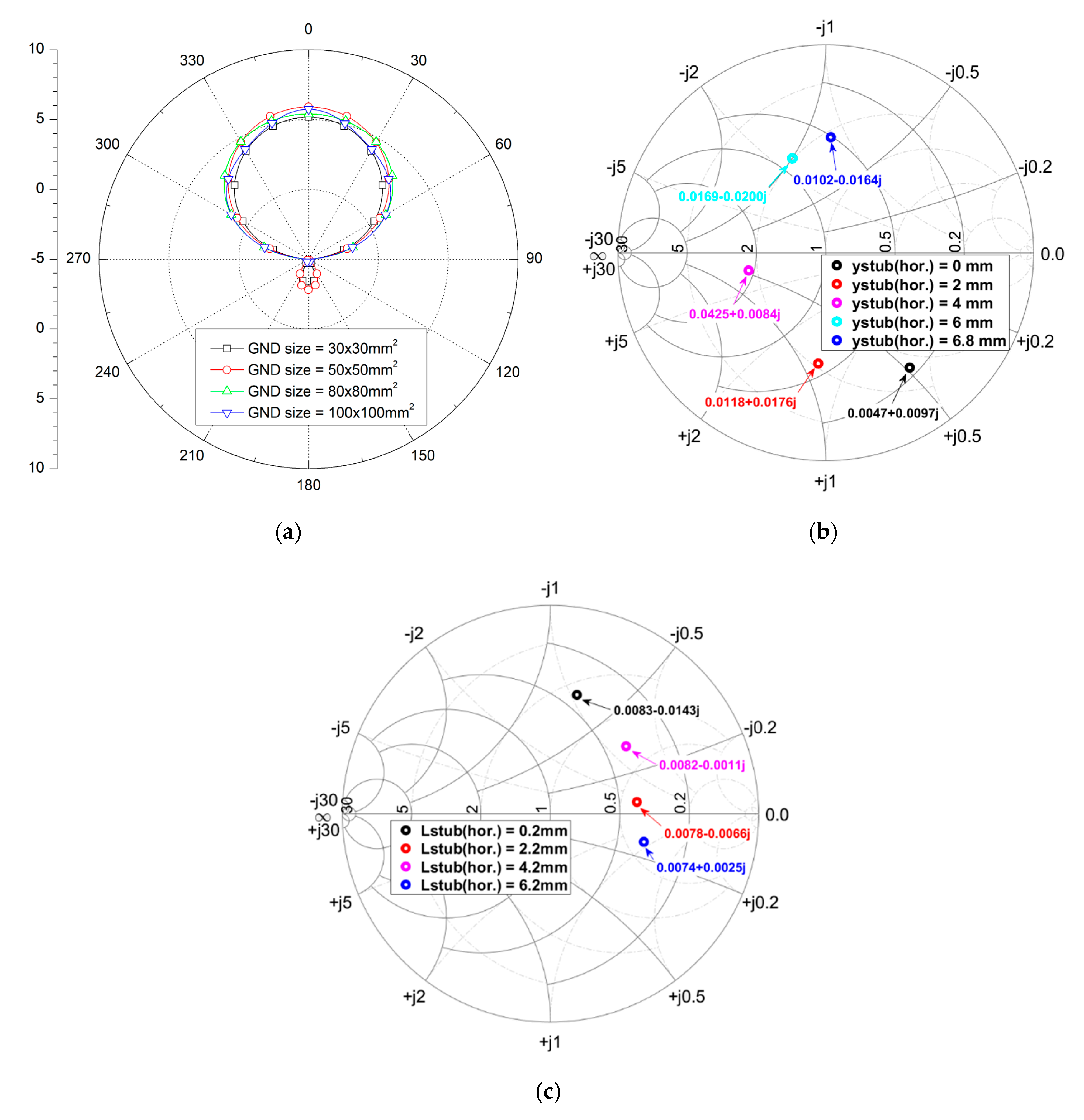
Since the radiation pattern of the proposed structure varied with respect to the height of the inverted arms, inclined angle, and length of each arm in the inverted-V dipole configuration, we performed the optimization process to determine each geometric parameter as described in Figure 2. First, in order to determine the optimized ground size, we simulated a single inverted-V dipole with respect to the changes in the ground plane size (Wgnd × Lgnd). The simulated radiation patterns on the xz-plane (referring to Figure 2b) for various ground sizes are shown in Figure 4a. For the purpose of faster simulation, the feed network was not included here and the optimized ground plane of 80 × 80 mm2 (1.5λ0 × 1.5λ0 at 5.8 MHz) was chosen for the broad beam pattern. Then, with the chosen ground plane size, the feed networks were included for the simulation. Referring to the geometric parameters of the feed network shown in Figure 2c, the stub sizes were optimized using impedance matching simulation as shown in Figure 4b.
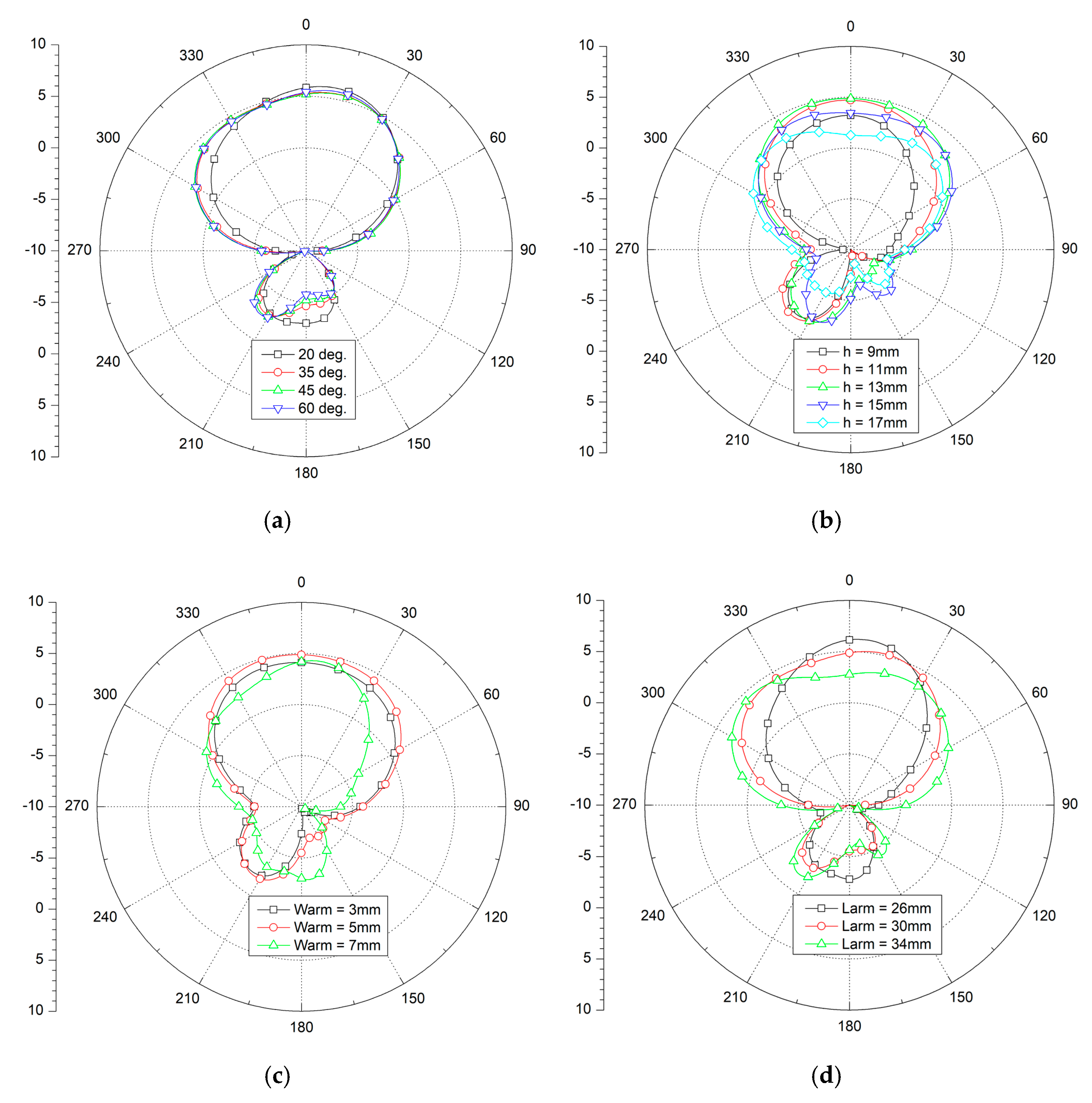
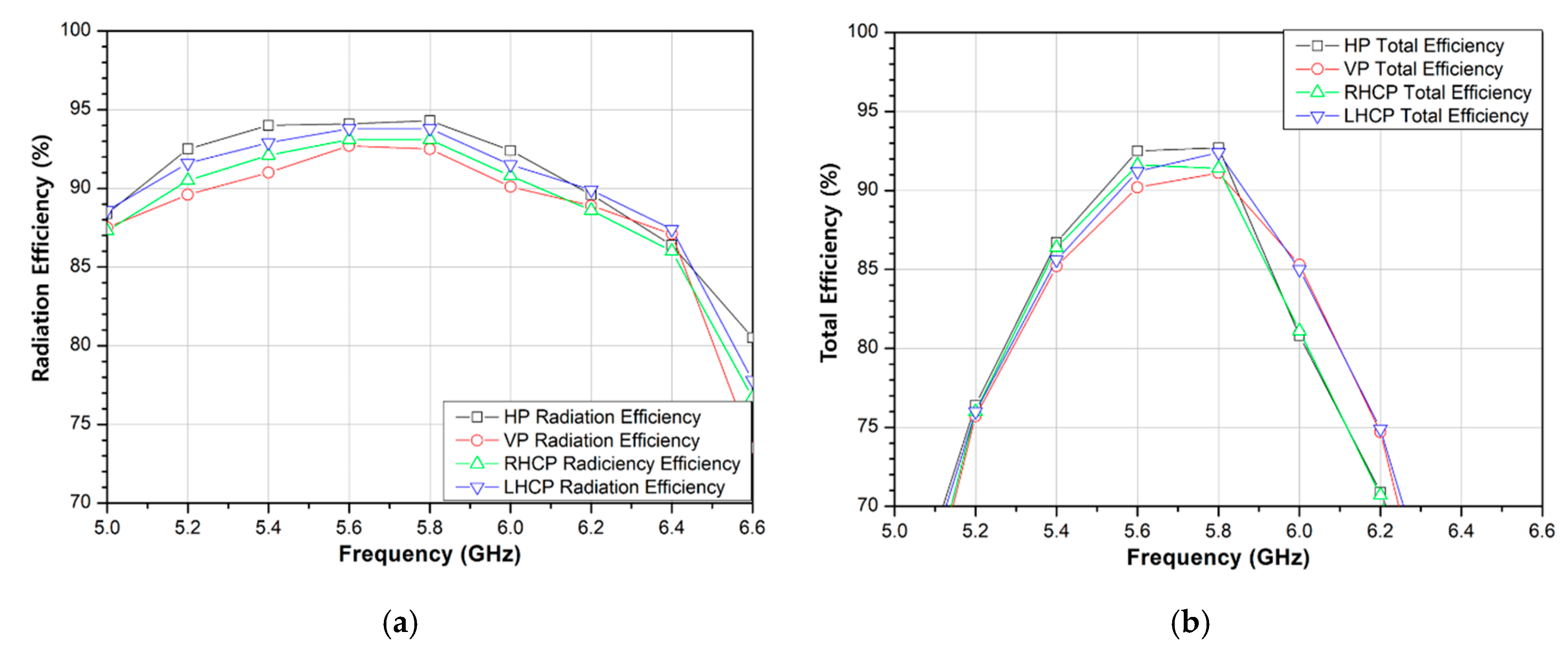
Once the feed network and ground size were determined, we simulated the radiation patterns for the different inclined angles (θ) of inverted-V arms as shown in Figure 5a. Since the half-power beamwidth (HPBW) characteristic changes according to the angle variation, we chose the optimized angle of 45° for the proposed structure to ensure the broad beam pattern. Then, we simulated the effect of the height of the inverted-V arms, as shown in Figure 5b. Here, the simulated result showed a strong dependency of the peak gain and HPBW on the height, resulting in the optimized height of 13 mm for the proposed structure. Lastly, we optimized the width and length of the inverted-V arms using the simulated radiation patterns as shown in Figure 5c,d, respectively. If the width and length of the arms become too large, the effect of the ground reflector for the inverted-V configuration decreases. Therefore, to optimize the balance in peak gain and HPBW characteristics, we chose 5 mm for the width and 30 mm for the length. In addition, Figure 6a,b show the simulated radiation efficiency and total efficiency, respectively. At the center frequency of 5.8 GHz, the radiation efficiencies for the HP, VP, RHCP, and LHCP were about 94.3%, 92.5%, 93.1%, and 93.8%, respectively. According to Figure 6a,b, the total efficiency decreases faster with being away from the center frequency because of the integrated feed network. Since we designed both the antenna radiation element and the feed network with the same substrate, which had the relative permittivity of 2.5, the low permittivity of the feed network caused extra radiation, resulting in the reduction in total efficiency. The total efficiency could be further improved by fabricating the feed network with a high permittivity substrate, although the fabrication cost would also increase due to the use of multiple substrates. Finally, we summarized these design parameters based on the 3-D EM simulations in Table 1.

3. Measurements

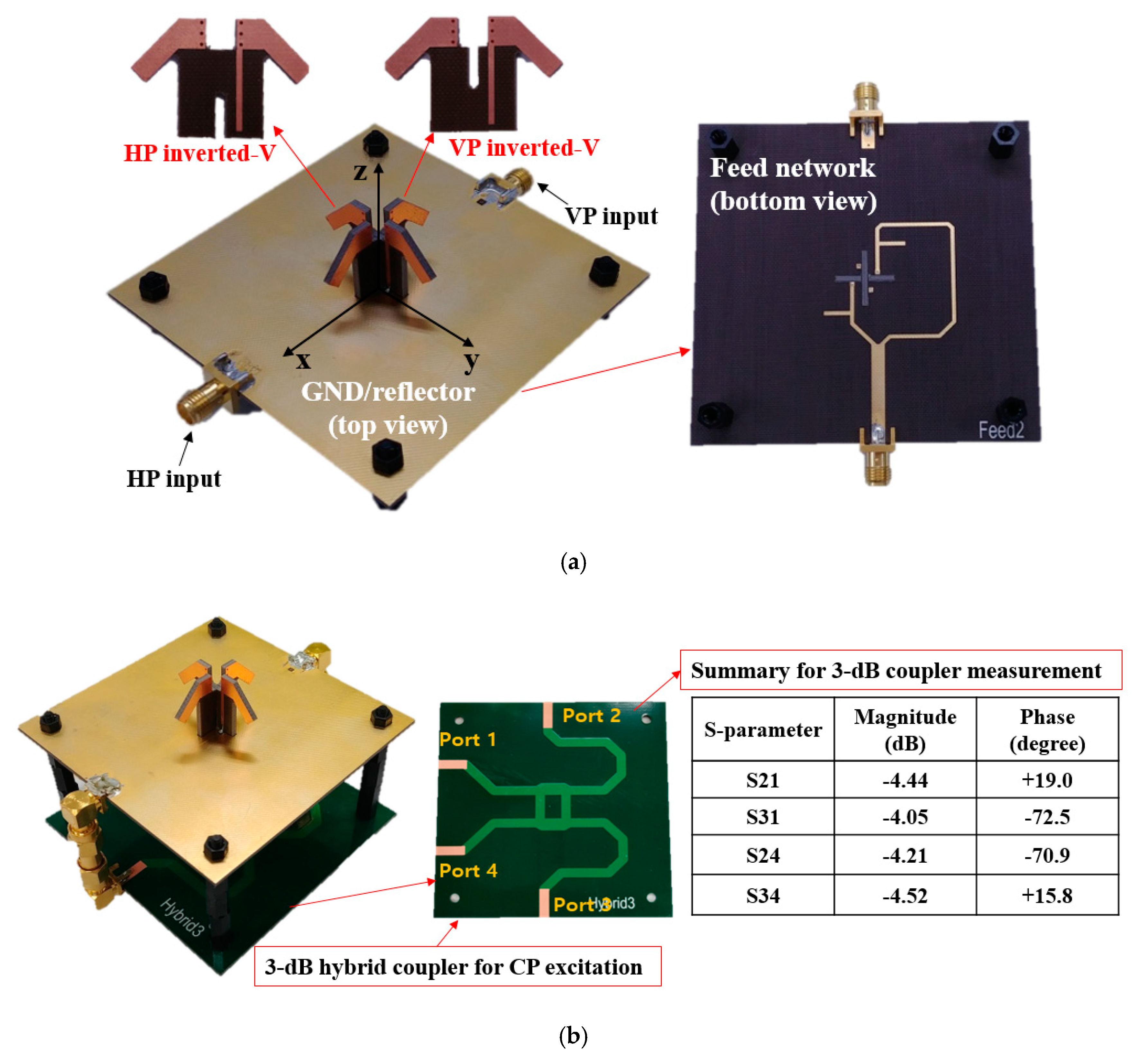
To verify the polarization diversity, we fabricated the proposed antenna with a Taconic TLX-9 substrate, which had a relative permittivity of 2.5. Figure 7 shows the implementation of the proposed inverted-V antenna with the design parameters summarized in Table 1. Two inverted-V antennas were fabricated in the crossed manner, and then they were integrated on the ground plane possessing the feed network as shown in Figure 7a. By using each input port at a time, the HP or VP could be generated. For CP verification, a 90° phase difference with equal magnitude was required at both the HP and VP input ports. Thus, a 3-dB hybrid coupler was implemented and used as shown in Figure 7b, where we also summarized the measured S-parameters at 5.8 GHz. According to Figure 7b, the measured magnitude deviation was less than 0.4 dB and the measured phase deviation was less than 3.5° at 5.8 GHz. Depending on the use of port 1 or port 4 of the hybrid coupler as an input port, the RHCP or LHCP could be excited.
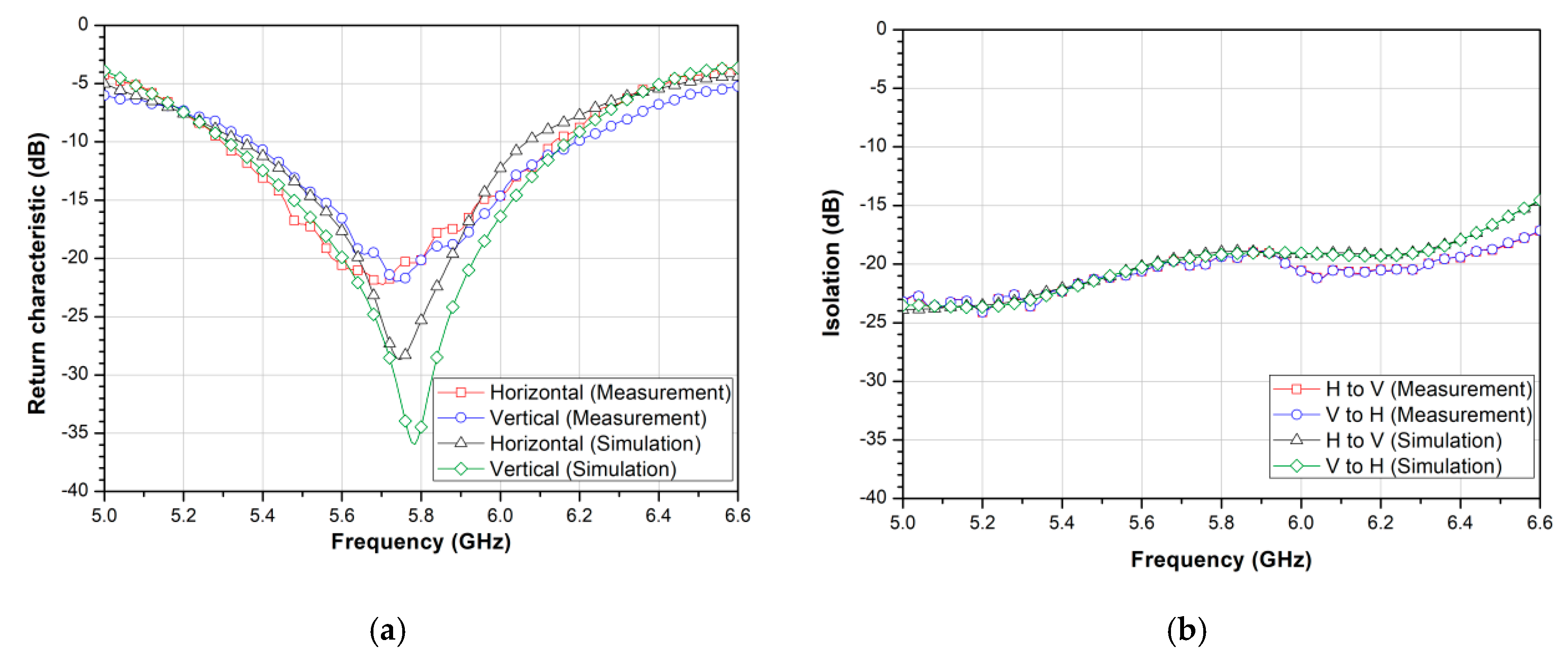
Figure 8 shows the measured return characteristics and isolation characteristics in comparison to the simulation results for the crossed inverted-V antenna. The proposed antenna showed a measured 10-dB impedance bandwidth (IBW) of 752 MHz (5.376 GHz to 6.128 GHz). In addition, the isolation between the HP and VP input ports was about 20 dB at the target frequency of 5.8 GHz.
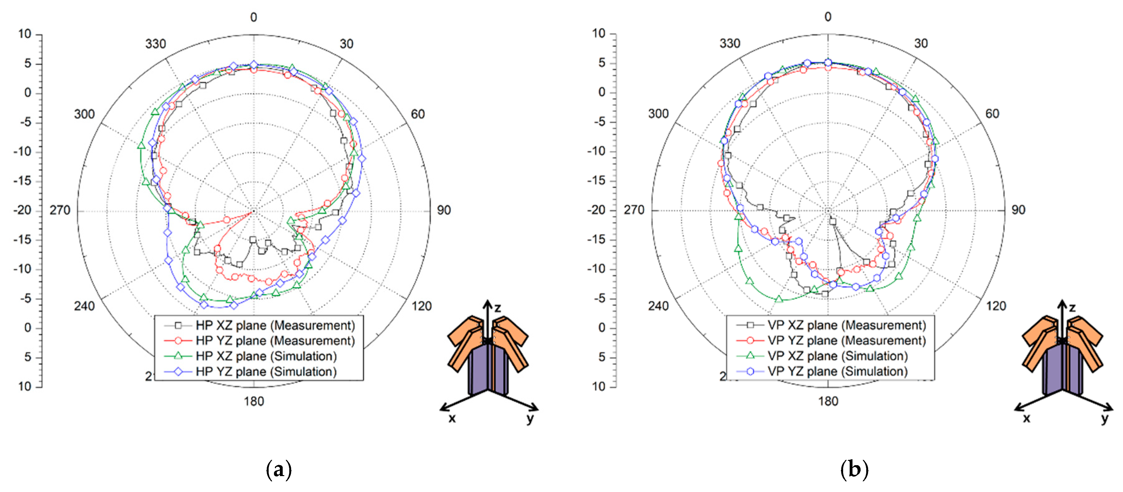
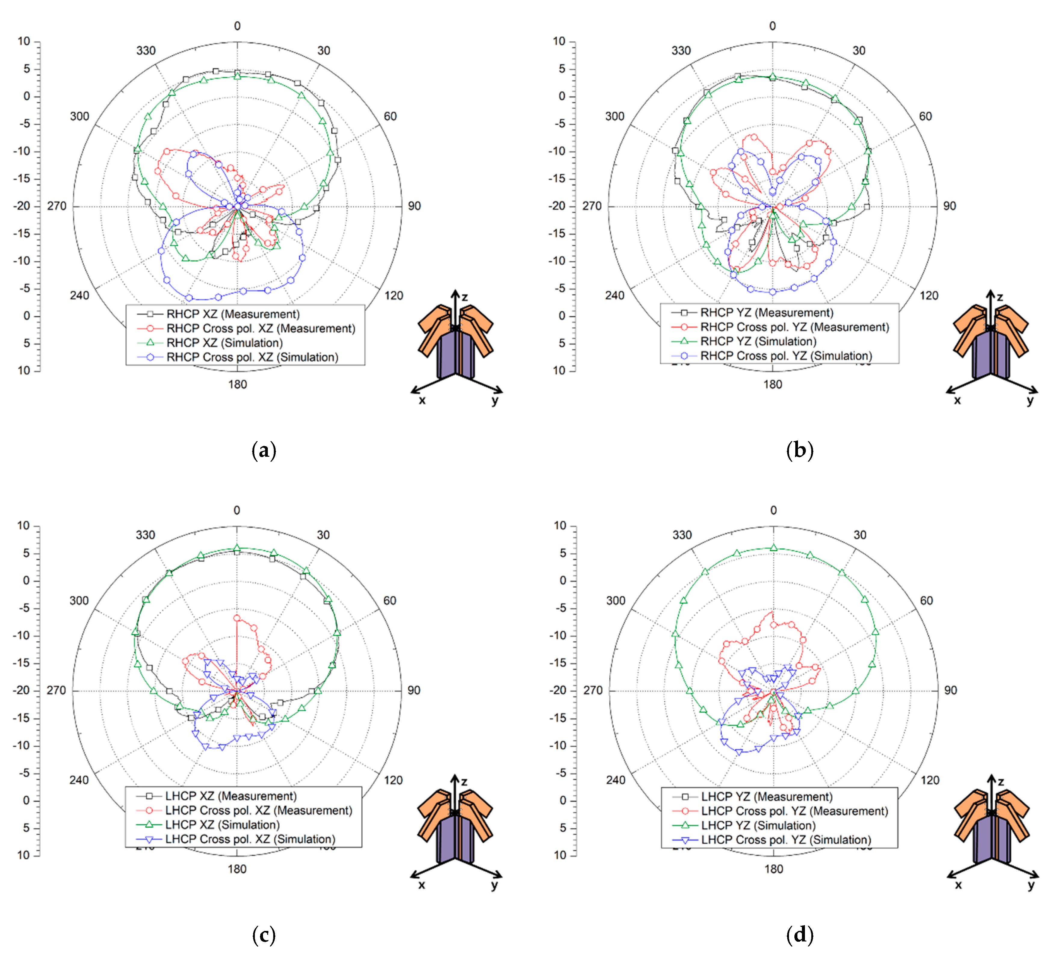
Figure 9 shows the simulated and measured radiation patterns for both the HP and VP on the xz and yz planes with good agreement. Table 2 summarizes the measured gain and HPBW for the HP and VP, as well as the measured gain and HPBW for the RHCP and LHCP. In addition, Table 2 also compares the ratios for gain to Q-factor. However, this ratio cannot be directly judged to reflect the electrical limitations like the electrically small antennas [28,29,30], since the proposed antenna has ka larger than 1. Finally, Figure 10 shows the simulated and measured radiation patterns with cross-polarization characteristics for both the RHCP and LHCP of the proposed antenna.
To compare the characteristics of the proposed antenna, we summarized some of the state-of-the art crossed dipole antenna configurations in Table 3. Here, the antenna volume denotes the radiation element’s pure volume excluding the ground plane size. The antennas in References [16,17] had conducting walls surrounding the radiation elements, thereby achieving high gains. However, the HPBW was sacrificed and extra conducting walls were required. Moreover, only a single type of polarization was verified in References [16,17,19]. Therefore, the proposed antenna overall showed an excellent qualification for IoT applications whilst possessing polarization diversity, compactness in size, and reasonable gain.

4. Conclusions

This article proposed a compact crossed inverted-V antenna with reconfigurable polarization characteristics. The proposed antenna could generate four different types of polarizations (VP, HP, RHCP, and LHCP), and it was analyzed using both 3-D EM simulations and measurements at 5.8 GHz. To verify the polarization diversity performance, we fabricated the proposed antenna with a Taconic TLX-9 substrate, which had a relative permittivity of 2.5. The overall volume of the proposed antenna including the whole ground plane was 80 × 80 × 15 mm3. The antenna showed a measured 10-dB impedance bandwidth of 752 MHz (5.376 GHz to 6.128 GHz). The peak gains for the VP, HP, RHCP, and LHCP operations were about 5.2 dBi, 4.61 dBi, 5.25 dBic, and 5.51 dBic, respectively, at 5.8 GHz. In addition, the HPBWs for all the polarizations were greater than 78°.

Author Contributions

Writing-original draft preparation and formal analysis, K.P.; investigation and validation, J.J.; validation and project administration, S.L.; writing-review and editing, and supervision, H.L.L.

Funding

This research was funded by the National Research Foundation of Korea (NRF) and Chung-Ang Univeristy.

Acknowledgments

This research was supported by the National Research Foundation of Korea (NRF) grant funded by the Korea government (MSIT) (2018R1A4A1023826) in part, and it was supported by the Chung-Ang University Graduate Research Scholarship in 2017 in part.

Conflicts of Interest

The authors declare no conflict of interest.

References

  1. Panwar, N.; Sharma, S.; Singh, A.K. A survey on 5G: The next generation of mobile communication. Phys. Commun. 2016, 18, 64–84. [Google Scholar] [CrossRef] [Green Version]
  2. Agiwal, M.; Roy, A.; Saxena, N. Next generation 5G wireless networks: A comprehensive survey. IEEE Commun. Surv. Tutor. 2016, 18, 1617–1655. [Google Scholar] [CrossRef]
  3. Andrews, J.G.; Choi, W.; Hanly, S.V.; Soong, C.K.; Zhang, J.C. What will 5G be? IEEE J. Sel. Areas Commun. 2014, 32, 1065–1082. [Google Scholar] [CrossRef]
  4. Wiklundh, K.; Stenumgaard, P. EMC challenges for the internet of things. In Proceedings of the IEEE EMC 2017, Angers, France, 4–7 September 2017. [Google Scholar]
  5. Xu, L.D.; He, W.; Li, S. Internet of things in industries: A survey. IEEE Trans. Ind. Inform. 2014, 10, 2233–2243. [Google Scholar] [CrossRef]
  6. Li, S.; Xu, L.D.; Zhao, S. 5G internet of things: A survey. J. Ind. Inf. 2018, 10, 1–9. [Google Scholar] [CrossRef]
  7. Cheng, J.; Chen, W.; Tao, F.; Lin, C. Industrial IoT in 5G environment towards smart manufacturing. J. Ind. Inf. 2018, 10, 10–19. [Google Scholar] [CrossRef]
  8. Al-Yasir, Y.I.A.; Abdullah, A.S.; Parchin, N.O.; Abd-Alhameed, R.A.; Noras, J.M. A new polarization-reconfigurable antenna for 5G applications. Electronics 2018, 7, 293. [Google Scholar] [CrossRef]
  9. Tang, H.; Zong, X.; Nie, Z. Broadband dual-polarized base station for fifth-generation (5G) applications. Sensors 2018, 18, 2701. [Google Scholar] [CrossRef]
  10. Qin, P.; Guo, Y.J.; Liang, C. Effect of antenna polarization diversity on MIMO system capacity. IEEE Antennas Wirel. Propag. Lett. 2010, 9, 1092–1095. [Google Scholar] [CrossRef]
  11. Sung, Y.J. Reconfigurable patch antenna for polarization diversity. IEEE Trans. Antennas Propag. 2008, 56, 3053–3054. [Google Scholar] [CrossRef]
  12. Wu, Y.; Wu, C.; Lai, D.; Chen, F. A reconfigurable quadri-polarization diversity aperture-coupled patch antenna. IEEE Trans. Antennas Propag. 2007, 55, 1009–1012. [Google Scholar] [CrossRef]
  13. Row, J.; Wei, Y. Wideband reconfigurable crossed-dipole antenna with quad-polarization diversity. IEEE Trans. Antennas Propag. 2018, 66, 2090–2094. [Google Scholar] [CrossRef]
  14. Su, D.; Qian, J.J.; Yang, H.; Fu, D. A novel broadband polarization diversity antenna using a cross-pair of folded dipoles. IEEE Antennas Wirel. Propag. Lett. 2005, 4, 3–5. [Google Scholar]
  15. Khaleghi, A.; Kamyab, M. Reconfigurable single port antenna with circular polarization diversity. IEEE Antennas Wirel. Propag. Lett. 2009, 57, 555–559. [Google Scholar] [CrossRef]
  16. Yang, W.; Pan, Y.; Zheng, S.; Hu, P. A low-profile wideband circularly polarized crossed-dipole antenna. IEEE Antennas Wirel. Propag. Lett. 2017, 16, 2126–2129. [Google Scholar] [CrossRef]
  17. Feng, G.; Chen, L.; Xue, X.; Shi, X. Broadband circularly polarized crossed-dipole antenna with a single asymmetrical cross-loop. IEEE Antennas Wirel. Propag. Lett. 2017, 16, 3184–3187. [Google Scholar] [CrossRef]
  18. Nakamura, T.; Honho, T. Single-fed crossed V-dipoles with four masts for circular polarization. Electron. Commun. 2002, 85, 44–51. [Google Scholar] [CrossRef]
  19. Feng, C.; Zhang, F.; Sun, F. A broadband crossed dipole antenna with wide axial ratio beamwidth for satellite communications. Prog. Electromagn. Res. Lett. 2018, 77, 59–64. [Google Scholar] [CrossRef]
  20. Parchin, N.O.; Basherlou, H.J.; Al-Yasir, Y.I.A.; Abd-Alhameed, R.A.; Abdulkhaleq, A.M.; Noras, J.M. Recent developments of reconfigurable antennas for current and future wireless communication systems. Electronics 2019, 8, 128. [Google Scholar] [CrossRef]
  21. Hu, W.; Wen, G.; Inserra, D.; Huang, Y.; Li, J.; Chen, Z. A circularly polarized antenna array with gain enhancement for long-range UHF RFID systems. Electronics 2019, 8, 400. [Google Scholar] [CrossRef]
  22. Iqbal, A.; Smida, A.; Mallat, N.K.; Ghayoula, R.; Elfergani, I.; Rodriguez, J.; Kim, S. Frequency and pattern reconfigurable antenna for emerging wireless communication systems. Electronics 2019, 8, 407. [Google Scholar] [CrossRef]
  23. Tsai, J.; Row, J. Reconfigurable square-ring microstrip antenna. IEEE Trans. Antennas Propag. 2013, 61, 2857–2860. [Google Scholar] [CrossRef]
  24. Ji, L.; Qin, P.; Guo, Y.J.; Ding, C.; Fu, G.; Gong, S. A wideband polarization reconfigurable antenna with partially reflective surface. IEEE Trans. Antennas Propag. 2016, 64, 4534–4538. [Google Scholar] [CrossRef]
  25. Fan, Y.; Li, R.; Cui, Y. Development of polarisation reconfigurable omnidirectional antennas using crossed dipoles. IET Microw. Antennas Propag. 2019, 13, 485–491. [Google Scholar] [CrossRef]
  26. Feng, B.; Luo, T.; Zeng, Q.; Chung, K. Frequency reconfigurable antenna with triple linear polarization and wide H-plane characteristic for future smart communications. IET Microw. Antennas Propag. 2018, 12, 2276–2284. [Google Scholar] [CrossRef]
  27. Bhattacharjee, A.; Dwari, S.; Mandal, M.K. Polarization-reconfigurable compact monopole antenna with wide effective bandwidth. IEEE Trans. Antennas Propag. 2019, 18, 1041–1047. [Google Scholar] [CrossRef]
  28. Chu, L.J. Physical limitations of omni-directional antennas. J. Appl. Phys. 1948, 19, 1163–1175. [Google Scholar] [CrossRef]
  29. Geyi, W. Optimization of the ratio of gain to Q. IEEE Trans. Antennas Propag. 2013, 61, 1916–1922. [Google Scholar] [CrossRef]
  30. Pigeon, M.; Clemente, A.; Delaveaud, C.; Rudant, L. Analysis of harrington limit for electrically small antenna directivity. In Proceedings of the 8th European Conference on Antennas and Propagation (EuCAP 2014), The Hague, The Netherlands, 6–11 April 2014. [Google Scholar]
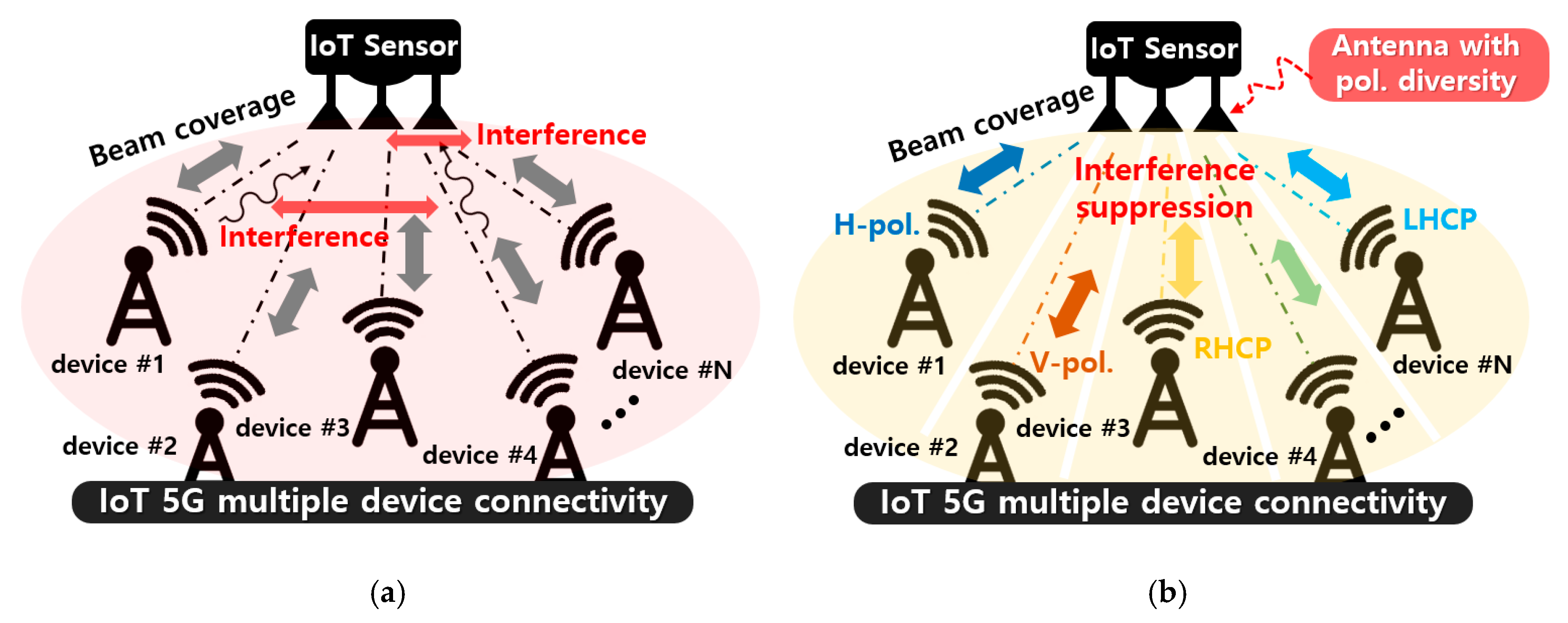
Figure 1. Multiple-input multiple-output (MIMO) communication of IoT sensors or devices through (a) a single polarization, and (b) polarization diversity (horizontal, vertical, right-hand circular, and left-hand circular polarizations).
Electronics 08 00637 g001
Figure 2. The proposed antenna structure with: (a) a 3-dimensional view, (b) a single inverted-dipole, and (c) a multi-layered feed network and layer information.
Electronics 08 00637 g002
Figure 3. Antenna feed network with tuning stubs for a single inverted-V dipole.
Electronics 08 00637 g003
Figure 4. Simulation for (a) the radiation patterns on the xz-plane according to different ground plane sizes, and the smith chart impedance matching using the (b) ystub (horizontal) and (c) Lstub (horizontal) of the feed network, referring to Figure 2c, at 5.8 GHz.
Electronics 08 00637 g004
Figure 5. Simulated radiation patterns according to the different (a) inclined angle, θ, on the xz-plane (b) height, h, on the yz-plane, (c) width, Warm, on the xz-plane, and (d) length, Larm, on the xz-plane of the inverted-V arms. Here, different radiation planes are plotted for the best view of variation.
Electronics 08 00637 g005
Figure 6. Simulated (a) radiation efficiency and (b) total efficiency over the operation frequencies.
Electronics 08 00637 g006
Figure 7. Implementation of the proposed crossed inverted-V antenna for the (a) horizontal polarization (HP) and vertical polarization (VP) test, and (b) the right-hand circular polarization (RHCP) and the left-hand circular polarization (LHCP) test with an additional 3-dB hybrid coupler.
Electronics 08 00637 g007
Figure 8. Simulated and measured (a) return and (b) isolation characteristics.
Electronics 08 00637 g008
Figure 9. Simulated and measured radiation patterns: (a) HP and (b) VP on both the xz and yz planes.
Electronics 08 00637 g009
Figure 10. Simulated and measured radiation patterns with cross-polarization characteristics for the (a) RHCP on the xz-plane, (b) RHCP on the yz-plane, (c) LHCP on the xz-plane, and (d) LHCP on the yz planes.
Electronics 08 00637 g010
Table 1. Design parameters of the proposed inverted-V antenna.
Inverted-VLarmWarmhθLgndWgndLstubystubWstub *
Horizontal30 mm5 mm13 mm45°80 mm80 mm6.2 mm6.8 mm1 mm
Vertical30 mm5 mm13 mm45°80 mm80 mm5.1 mm6.4 mm0.5 mm
* Wstub denotes the width of the stubs used in the feed network.
Table 2. Measured gain, the half-power beamwidth (HPBW), and Gain/Q ratio of the proposed antenna.
HP (XZ/YZ)VP (XZ/YZ)RHCP(XZ/YZ)LHCP (XZ/YZ)
Gain4.43 dBi/4.61 dBi4.40 dBi/5.20 dBi4.67 dBic/5.25 dBic5.51 dBic/4.41 dBic
HPBW82°/94°78°/106°91°/101°106°/110°
Gain/Q0.57/0.600.57/0.600.61/0.680.71/0.57
Table 3. Comparison table with the previously reported crossed-dipole structure.
Ref.Center Freq. (GHz)Volume (λo3) *kaPeak Gain (dBic)HPBW (°)IBW (%)Polarizations
[16]5.51.28 × 1.28 × 0.134.0310.4-66.9RHCP
[17]5.51.57 × 1.57 × 0.314.9610.62-67.5RHCP
[19]2.80.51 × 0.51 × 0.351.614.818770.6RHCP
This work5.80.58 × 0.58 × 0.251.825.5111013.0HP, VP, RHCP, LHCP
* λo denotes the free-space wavelength at the center frequency.