Abstract
Unmanned aerial vehicles (UAV), like other complex mechatronics systems, use servomechanisms for the accurate positioning of construction elements. Servomechanisms are stable, reliable and easy to control. However, occasionally they fail and cause issues for the electrical system. In this paper, the authors present a full analysis of the system operations after a specific fault and the consequences of it. The authors propose a test bench and show the experimentation results that contain servo motor electrical parameters at loaded and idle states, the relations to the manufacturer technical specifications, and possible fault detection and elimination solutions. The obtained results could be implemented into existing popular UAV control systems to improve reliability and fault tolerance of commercial products.
1. Introduction
In mission-critical systems where reliability and safety are a priority, the investigation of the weakest link of the whole system of developed unmanned aerial vehicles (UAV) architecture must be performed [1]. At the moment, most UAVs are developed without such analysis because it is considered that the reliability of all electrical, electronic and electro-mechanic components is sufficient. This does not apply to major aerospace companies that strictly adhere to engineering standards. Very rarely, support is given for the time and resources to investigate and design reliable systems. However, in rare cases, components can fail, which influences the operations of the entire system and could lead to failure of the whole project.
Failures of servomechanisms and the faults they influence can be different. For example, the servomechanism could be stuck in a non-correct position or a short circuit could occur, or at the starting moment current or voltage values could exceed maximum possible values, or external influence could be too high. These variables could cause a significant increase in current usage by a broken device. The fault of the entire system happens at this moment because the supplied voltage drops significantly and not all components can receive enough electrical power to function correctly. UAVs may become uncontrollable and unsafe. They might not only cause the destruction of a vehicle, but additional serious damage to the ground objects or persons as well.
Investigation of servomechanism reliability for low-cost UAVs is widely discussed in remote control model and UAV related forums, and an open source project named OpenServo of improved servomechanism controller was initiated [2], but no fully applicable solution is found. The scientific approach to this problem is very limited–only a few papers were found. The testbed for measuring servomechanism, which is used in Boeing Insitu ScanEagle to control its ailerons position under variable load, is presented and positioning accuracy is evaluated [3]. The experimental determination of servomechanism reliability, based on measurement of operation time to failure and statistical evaluation using the Weibull model to obtain the failure rate profile is presented [4]. These results can be useful for evaluation matching the requirements of low-risk UAV operations, but no cause analysis and improvement solutions are presented. In addition, the redundant power bus for reliable UAV operation is discussed [5], but the presented solution is only oriented to eliminate the impact of supply faults.
Some recommendations for practical motor protections are provided by the Institute of Electrical and Electronics Engineers (IEEE) [6]. In any case, the methodology needs to be developed to check the performance of the servomotors by externally applying forces of different sizes in order to create fault prevention measures. In addition, the methodology could allow for quick testing of the servo motors before integrating them into the system.
For example, the estimation of the amount of the external force by measuring the motor drive current is proposed in [7]. The system estimates the external force using a current sensor, where current is provided by a power supply and calculates the output angle.
To understand external forces needed for estimates it is good practice to understand the mathematical model of the servo motors. Mathematical models are presented in [8,9,10]. The mathematical model of the servo motor gives a brief description of the physical and electrical structure of the analysed device with constraints.
To supply the internal equipment of UAV and other remote-controlled objects, the universal battery eliminator circuits (UBEC) which functions as a voltage regulator are often used. Principally it is a simple voltage regulator, which converts the main battery pack voltage to a lower voltage for the controller and servomechanisms supply. Typically, the output voltage is equal to 5 V or 6 V, and the UBEC inside is a linear or switching buck converter, which has some internal circuitry for overload protection. In case of failure, this device isolates the load from a battery pack, but it does not monitor faults or there is no possibility of isolating only damaged devices.
There are a number of possibilities to solve such issues. For example, authors in [11,12] propose an integrated driver solution for the monitoring of the motor work that provides current sensing and fault/protection feedback. However, for the simple servo motor control, it is not needed due to direct control by pulse wide modulation (PWM), where only power supply monitoring is needed.
For overcurrent monitoring and protection, the Fuzzy logic and neural network algorithms are proposed at [13,14]. Here authors are solving identical problems where the starting current is very high. Authors proposed to monitor current and time moment when overcurrent appears. If overcurrent takes too long, fuzzy logic or other algorithms make the decision to power off a motor. Solution size and price increases because of microcontroller usage in this approach.
Using inverters for the overcurrent protection are proposed in papers [15,16]. In this case, algorithms decrease voltage reference if overcurrent is detected.
In this paper, authors solve overcurrent protection for the airplane with the mass of a few kilograms. The analysis section explains object characteristics, electrical and data flow architecture, discuss possible weaknesses, and shows malfunction consequences of the servomotors. In the research section, authors present experimental results of the tested servomotors and summarize recommendations for the reliability improvements. The solution is based on adding prediction and prevention of the fault abilities to the system, and fault-tolerance–keeping the system operational when hardware or software faults occur [17], supporting the increase of safe operation and life-cycle conditions [18,19].
2. Materials and Methods
The Spartan UAV fixed wing aircraft (Figure 1) was developed for reconnaissance tasks. A unique feature of aircraft is the hand-launch start with the capability of accommodating quite large payload of up to 2 kg. The total mass of this aircraft is up to 14 kg (depending on configuration).
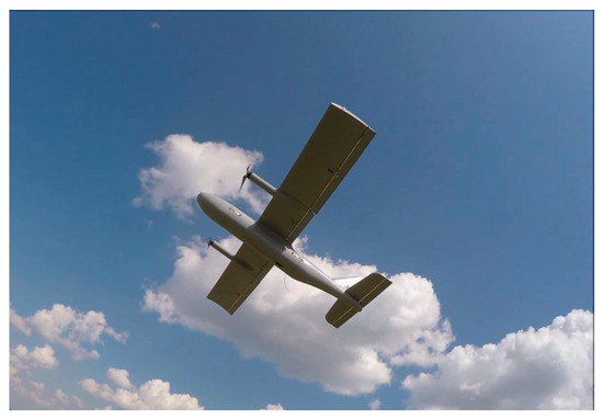
Figure 1.
The “Spartan” unmanned aerial vehicle (UAV) in flight.
The aircraft propulsion is ensured by two low speed (which ensure minimal noise level) brushless alternating current (AC) electric motors. To perform fully automated operations the aircraft is equipped with a PixHawk type autopilot. The entire electrical system is powered by a 6S (18–25.2 V) 25–50 Ah lithium polymer battery. The aircraft control system is powered by 5 V supply, which is obtained via several voltage converters (BECs). A basic structural diagram of the aircraft power system is shown in Figure 2.
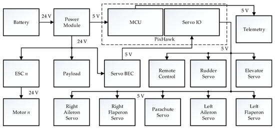
Figure 2.
Typical diagram of unmanned aircraft power supply chain.
As can be seen from Figure 2, the aircraft is powered from the 6S (18–25.2 V; 24 V nominal) 25–50 Ah lithium polymer battery. The main power consumers in the system are two brushless electric motors, which consume up to 60 A (30 A each) during takeoff and ascent of an aircraft and 8–10 A during the cruise flight. The main aircraft control system (aircraft control servos) is powered by a single 10 A 5 V voltage converter. The autopilot and its systems (telemetry etc.) are powered from the separate 3 A 5 V voltage converter to ensure the power separation from the main 5 V system (since noise produced by power servomechanisms often disturb the normal functioning of the sensitive autopilot systems), therefore functioning of autopilot is fully power separated from the aircraft servomechanism control. The aircraft motors are powered by the dedicated engine speed controllers (ESCs); the function of ESC is to convert the battery provided direct current (DC) to 3 phase AC powering the motor and changing the voltage and frequency of AC to ensure motor RPM control.
The system shown in Figure 2 is quite basic and very widely implemented for controlling most UAV vehicles. Voltage converters are considered quite reliable and not in need of any backup systems.
As can be seen from Figure 2, all of the servomechanisms in the Spartan aircraft are powered from a single voltage converter. In addition to normal control servos (aileron, elevator, rudder) Spartan aircraft does have the safety feature in the form of a parachute which automatically deploys at a certain preset minimal altitude; the parachute is deployed by the specially dedicated servomechanism which is powered from the same system.
During one of the aircraft test flights (second flight during the same day) on the 7th minute of the automated flight, the aircraft started losing control and descending rapidly. The malfunction was noticed by the operator and the aircraft control was switched to manual which allowed for a regaining of control for a certain time; nonetheless, in less than a minute the aircraft went out of control again, dived and crashed into the ground. Neither automated parachute deployment nor the manual one worked as expected.
After the post-flight analysis of logged data, it was determined that the loss of control was caused by a rapid decrease in the aircraft servo control power circuit. The normal 5 V voltage in the servo circuit dropped down to 2.5–3 V at a certain moment. The graph showing the normal 5 V supply voltage and its drop during the flight is shown in Figure 3.
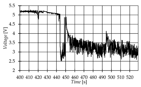
Figure 3.
The voltage diagram of servomechanism power supply logged during the crash.
As can be seen from the graph (Figure 3) the normal 5 V voltage rapidly dropped during the flight and did not regain until the crash. The battery voltage (24 V nominal) and the autopilot voltage (5 V) were normal (therefore the autopilot continued functioning and writing the flight data to its memory). According to further investigation it was determined that the aircraft servos would remain barely controllable (though with much lower torque) at the power voltage of down to 3 V and would totally lose control at the voltage of 2.5 V. Therefore, it was obvious that the aircraft lost control due to the rapid drop of voltage in the servomechanism supply circuit below the allowed minimum. The same reason caused the impossibility of parachute deployment.
During the crash investigation, a burned parachute servomechanism was discovered, the wires of the servo were cut during the crash, therefore it was concluded that the servomechanism burned (short-circuited) before the crash happened. Further investigation showed that the 5 V voltage converter in case of short-circuiting (of one of the consumers) and an increase in current consumption drops down the voltage instead of malfunctioning. Since no other malfunctions in the electric system were discovered (other servos functioned properly after the crash) were concluded the parachute servomechanism failed during the flight (due to unknown reasons), short-circuited the power converter, which increased the current in it. That caused the output voltage drop in the servomechanism voltage converter down to 2.5–3 V, a low voltage not sufficient for normal servo functioning, and the aircraft control servos ceased functioning or were not functioning improperly. Due to the loss of servo control, the aircraft control was lost as well (due to the short-circuiting of parachute servo the parachute could neither be deployed).
The damaged servomechanism (type DS339HV, made by Corona) was taken under detailed examination with an objective to find a reason for the fault. Pictures of the disassembled servomechanism are presented in Figure 4. The electronic circuitry was found totally damaged; most of the parts were de-soldered because of overheating, and motor control transistors also short-circuited. Motor wiring had visibly overheated as well.
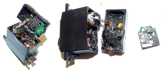
Figure 4.
Pictures of servomechanism from the crashed plane.
For a better understanding of the circuitry of damaged servomechanism, the similar one was taken under examination. The typical H-bridge for the brushed DC motor control was found. This H-bridge consists of AO4800B type dual n-channel metal-oxide-semiconductor field-effect transistor (MOSFET) and AO4801A type dual p-channel MOSFET, both in SOIC-8 packages, directly connected to the incoming power supply wires. None of the internal overcurrent protection circuitry was found. Motor winding parameters for both servomechanisms were measured: resistance R = 2.50 Ω and inductance L = 435 μH for the new one and R = 1.23 Ω, L = 28.3 μH for the damaged, so the internal short-circuited winding is obvious in a damaged servomechanism. No damages in internal gear circuit were found. In conclusion, a possible reason for the fault was an external mechanical overload on the servomechanism axis, which raised the motor overcurrent and overheating with sequential destruction of winding and control circuitry. Decreased servomechanism resistance overloaded the power supply line, and the internal protection circuit of UBEC reduced the output voltage. As a result, all other servomechanisms connected to the same UBEC supply became inoperative, and there was no one circuit for protection.
To avoid this kind of accident it should be possible to install individual overload monitoring and protection circuits for all connected devices, and set the protection parameters corresponding to working conditions and power consumption parameters. At the moment, on the market there are several types of servomechanisms for UAV usage: analogue and digital controllers, with brushed or brushless DC motors, and very different parameters. For accurate protection circuit design, detailed knowledge about the current consumption, parameters of exact servomechanism at exact load conditions are required, and this data cannot be collected directly on the plane.
For the servomechanism examination under different load conditions, the custom test bench (Figure 5) was made. The servomechanism was mounted on exchangeable steel plate 1 to make the test bench universal for different size servomechanisms. For the measurement of the tension force of the spring 2, the usual luggage weighing scale 3 was installed. For the adjustment of the tension force, the screw 4 was used. To keep the scale joint to the screw on axial line the rigid screw mount using two right angle couplings was made, and the tough enough M10 steel screw was used. The luggage weighing scale with a maximum load of 40 kg and resolution of 20 g was used. Schematic diagram of the test bench is presented in Figure 6.
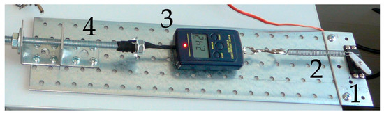
Figure 5.
Test bench for the servomechanism examination under adjustable load torque.
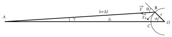
Figure 6.
Schematic diagram of the test bench for the servomechanism examination.
The magnitude of the torque τ on the servomechanism axis O (Figure 6) is a product of the lever arm length r and the perpendicular component F┴ of the tension force F (1):
where θ is the angle between the force vector and the lever arm vector. Because θ is an external angle of triangle ABO, it can be expressed as a sum (2):
where α is an angle of the servomechanism arm from an initial position on the axial line, and γ is an angle of the spring deviation from the axial line. The deviation angle γ can be calculated using an Equation (3):
where l0 is the initial distance between the scale and the adjustment screw joint point A and the spring connection to the servomechanism arm at point C. Extension Δl of the spring if the arm of the servomechanism rotated by angle α can be calculated using the Equation (4):
The spring tension force F is proportional to the extension Δl and can be expressed as a sum of initial tension force F0, measured when the arm of the servomechanism is on an axial line, i. e., angle α = 0, increase of tension force by the extension Δl, presented in the Equation (5):
where k is the spring constant. Finally, the torque applied to the servomechanism axis can be calculated using Equation (6):
where γ can be calculated using Equation (3). Equations (3)–(6) were implemented in the MS Excel spreadsheet, and calculated values compared to the measured tension force results for the model verification. For the used equipment the spring constant k = 750 N/m was found experimentally measuring the increase of tension force on the extension. The estimated torque dependences on servomechanism arm angle for defined initial tension force F0 = 10; 20; 30 and 40 N are presented in Figure 7. For calculations, servomechanism arm length r = 15 mm was used, and initial distance l0 = 0.258; 0.271; 0.284 and 0.298 m for the defined tension force was measured on the built test bench. These dependencies have sufficient linearity in the usual ± 50° arm rotation range for plane model servomechanisms and matches measured results, so calculated torque values can be used for experimental tests.
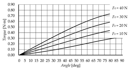
Figure 7.
The estimated torque dependence on servomechanism arm angle for defined initial tension force F0.
For the servomechanism current measurement, the high-side shunt resistor with an INA169 type unipolar current monitor was used (Figure 8).
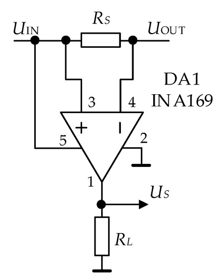
Figure 8.
Schematic diagram of the servomechanism current measurement circuit.
Because the operating current values of servomechanisms under tests were below 3.5 A the shunt resistor value RS = 0.1 Ω was selected. The load resistor value RL = 10 kΩ was used, and as a result the current monitor output voltage , i.e. the output voltage, was proportional to the load current as 1 A to 1 V.
The full setup for the experimental servomechanism examination is presented in Figure 9. The setup consists of a steel plate mounted servomechanism 1, spring 2, weighing scale 3, adjustment screw 4, high side current shunt circuit 5, servomechanism control circuit 6, voltage regulator (UBEC) TURNIGY UBEC-7.5A 7 (for better match the real supply conditions in plane), 12 V 20 A power supply 8, four channel oscilloscope ROHDE&SCHWARZ HMO3034 9 for the current and voltage shape measurement, and digital multimeter MASTECH MS8059 with computer interface 10 for average current measurement.
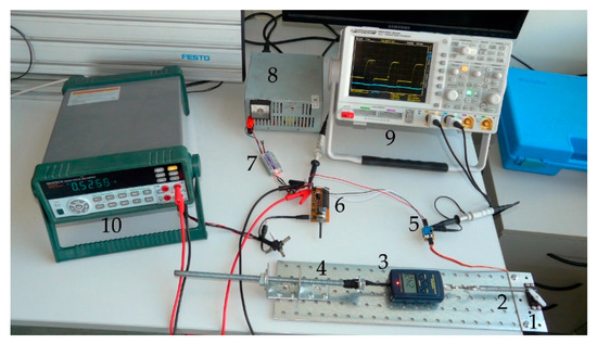
Figure 9.
Equipment setup for the servomechanism examination under adjustable load torque.
3. Results
For a detailed investigation, the same model to the damaged servomechanism (type DS339HV, made by Corona) was taken. This is a 32.5 × 17 × 34.5 mm size 32 g weight digital servomechanism with metal gear, which can work with supply voltage up to 7.4 V. The manufacturer declared parameters are presented in Table 1 [20].

Table 1.
DS339HV manufacturer declared parameters [20].
For the supply voltage 5 V parameters are not declared, but if calculated using proportional reduction operating current should be 0.28 A, and stall torque equal to 0.35 N∙m. Measurements were made using supply voltage equal to 5 V, 6V and 7.4 V, with variable load in the fixed servomechanism arm angle position in range ± 50° and travelling from 0 to 50° and backwards arm angle position. The measured idle current was equal to 3.2 mA at all used supply voltages.
The 20 N load force at 0° servomechanism arm position was selected for the measurement result representation because of the match the real load conditions–using the arm with length r = 15 mm in angle range from 0 to 50° the load torque linearly increased from 0 to 0.288 N∙m. The obtained current measurement oscilloscope pictures using a 5 V power supply are presented in Figure 10.
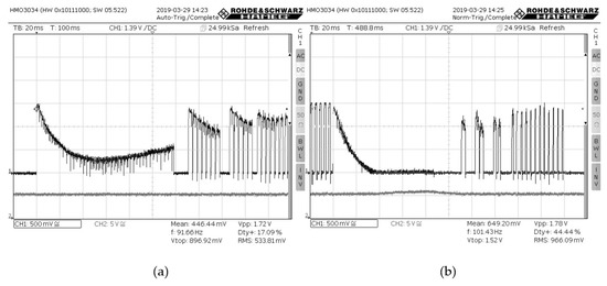
Figure 10.
The DS339HV servomechanism current diagram rotating from 0° to 50° arm position (a) and from 50° to 0° position (b) with a 5 V power supply and initial tension force F0 = 20 N.
The upper line (channel 1) represents the servomotor current change (0.5 A per division) rotating from 0 to 50° arm position (torque changes from 0 to 0.288 N∙m) in Figure 10a, and rotating from 50° to 0 arm position (torque changes from 0.288 N∙m to 0) in Figure 10b. The lower line (channel 2) shows the supply voltage (5 V per division). Rotation with increasing load torque shows a high current jump at startup where the maximum value (approximately 1.57 A in this case) is limited only by active circuitry resistance, and a further exponential decrease in around 50 ms. At this point, the current starts to linearly increase until the defined position is reached in 120 ms after the start. The final positioning process depends on implemented regulator firmware, and in this servomechanism takes another 130 ms adjusting the motor current by pulse width modulation (PWM). The resulting values, in this case, were measured–the current maximum level at 1.57 A, modulation frequency 252 Hz, duty cycle 48% and mean value 0.75 A. The defined position is continually regulated in ~130 ms cycles. Rotating from 50° to 0 arm position external force supports the movement, and the motor current decreases to 0 in 35 ms after start (Figure 10b). The defined position is reached in 110 ms after the start, and from 35 to 110 ms of the movement, an increase of supply voltage in 20 % can be observed because of motor turn to the generation mode. After that, the ~90 ms current pulses shows the final positioning by regulator firmware.
Investigation of the servomechanism under different load and positioning conditions resulted in similar processes with only different duty cycle and mean current values or timing changes. The main difference is only for stall torque below ~0.16 N∙m, when the gearbox braking is enough to keep position without additional motor force and current consumption. If the stall torque exceeded this value, or servomechanism was in continuous cycling mode, the heating of the motor was noticed. During the tests two similar servomechanisms were damaged: one after a 2 min position keeping process with 0.288 N∙m stall load, and another after a similar time of cycling from 0 to 0.4 N∙m. Both damaged servomechanisms had similar symptoms: short circuit of motor windings (R = 0.308 Ω, L = 0.549 μH and R = 0.297 Ω, L = 0.959 μH) and part of H bridge transistors. The resulting increase in current consumption for damaged servomechanisms is presented in Figure 11. Because of only one damaged motor winding the current on stall torque load (Figure 11a, first 40 ms) seems to be unaffected, but rotating the peak current spikes reaches 3.8 A. At the next turn to the 50° position (Figure 11b), where oscilloscope settings were changed to 1.0 A per division, it is visible in more detail, and the average current increase is obvious–mean value is shown equal to 2.46 A. Because of current increase, the supply voltage pulsations are increased as well (lower line in Figure 11a,b).
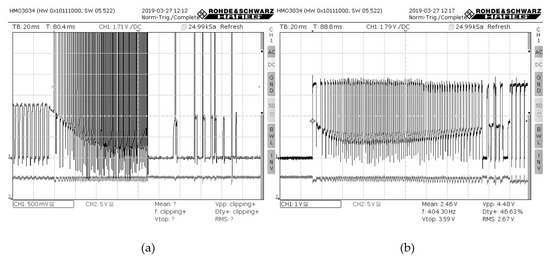
Figure 11.
Current diagrams of the damaged DS339HV servomechanism rotating from 50° to 0° arm position (a) and from 0° to 50° position (b) with 5 V power supply and initial tension force F0 = 20 N.
Resuming investigation of the Corona DS339HV servomechanism there could be noted, that the manufacturer declared stall torque value was not exceeded, but the measured operating current values exceeded the declared ones, and it causes overheating and damages of servomechanisms. Therefore, for the reliable circuit protection design, the appropriate investigations should be made; peak and average current values should be measured for the corresponding load.
Servomechanisms for UAV usage are made using different technologies, not only brushed DC motors. The usage of brushless DC motors in servomechanisms grows up, and the internal circuitry can vary. For the comparison, the GOTECK BL1511S was selected. This is a 40.8 × 20.2 × 26.1 mm size 45 g weight brushless digital servomechanism with metal gear, which can work with supply voltage from 4.8 to 6.0 V. The manufacturer declared parameters are presented in Table 2 [21].
Table 2.
BL1115S manufacturer declared parameters [21].
For the BL1511S servomechanism, investigation of the 10 N load force at 0° servomechanism arm position was selected for the measurement result representation because of the match of the real load conditions, using the arm with length r = 18 mm in angle range from 0 to 50° the load torque linearly increases from 0 to 0.168 N∙m. The obtained current measurement oscilloscope pictures using a 5 V power supply are presented in Figure 12. The upper line (channel 1) represents the servomotor current change (0.5 A per division) rotating from 0 to 50° arm position (torque changes from 0 to 0.168 N∙m) in Figure 12a, and rotating from 50° to 0 arm position (torque changes from 0.168 N∙m to 0) in Figure 12, b. The lower line (channel 2) shows the supply voltage (5 V per division). The measured idle current consumption was equal to 43 mA, the current at 0.168 N∙m stall torque load–0.411 A, at 0.360 N∙m–0.836 A, at 0.502 N∙m–1.95 A. The current pulses had much better filtering in comparison to DS339HV servomechanisms; pulsations on stall torque load were below 0.5 A, but the starting current increase remains high; measured peak reaches 3.0 A (Figure 12b). Therefore, for the reliable circuit protection design, the different mechanisms of overload detection should be used for the investigated servomechanisms.
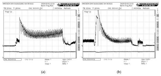
Figure 12.
The BL1511S servomechanism current diagram rotating from 0° to 50° arm position (a) and from 50° to 0° position (b) initial tension force F0 = 10 N.
4. Discussion
The simplest way to eliminate the fatal impact of the malfunctioned no mission-critical device to the whole system is a solution to have separate power supplies for components, or use separate power converters with short circuit protection (UBECs). This solution can be inconvenient due to additional costs, weight and power consumption, so there is a reason to design an intelligent power distribution system with an ability to evaluate healthiness of every device, log the data, send a report and make a decision about necessity to disconnect or limit some consumers when fault is detected to keep the system operable. The controller of the power distribution system should have a separate power supply converter from controlled devices to avoid influences of malfunction. The implementation of overcurrent protection into servomechanism as it was done in OpenServo [2] project cannot be accepted as a reliable solution because the controller will become powerless if the H bridge transistors are shortened.
The primary aircraft aerodynamic control surfaces, which are critical for the flight (or emergency landing) and the functionality of which servomechanism has to be tested, even in case of partial failure: ailerons, elevator. Parachute release servomechanism can also be considered as critical in some cases; nonetheless, parachute servomechanism becomes critical only in case of failure of one of the above-mentioned control servomechanisms. Aileron servomechanisms are critical for aircraft control, although malfunction of one of the servomechanisms in some cases does not lead to critical situations (depending on conditions). Nonetheless, malfunction of elevator servomechanism will most likely lead to the total loss of control of an aircraft.
The non-critical servomechanisms (in particular Spartan UAV) could be considered: flaps, rudder. In the case of malfunction of one of the flap servomechanisms, it would be preferable to deactivate the servomechanism on the other side of a wing to avoid asymmetrical lift of a wing and therefore the roll. Nonetheless, since the position of a failed servomechanism (and therefore the position of flap) could not be known, deactivation of the opposite flap servomechanism might not have an expected effect in some cases. Rudder deactivation in flight is not considered critical or dangerous since rudder control does not influence performance of a fixed-wing aircraft too much.
The intelligent power switches with overload protection are not new. They are widely used for automotive, avionics and other mission-critical operations. For example, on the market single drivers with an analogue current sense for automotive operation can be found [22], providing inrush current active management by power limitation, overtemperature and under voltage shutdown, overvoltage clamp, and off-state open-load detection, applicable for resistive, inductive and capacitive loads. The application examples for different types of loads and parameter adjustment guidance are provided by the manufacturer [23]. Similar solutions are provided by different manufacturers, including multichannel switching with individual current limiting adjustment. Some products have individual automatic restart timers with programmable delay time and restart period [24], or different types of operations (re-triggerable, latched or foldback) can be selected, including the ability to operate in a rad-hard environment [25]. In our case, the overcurrent protection should be provided for the dynamically variable load; the peak, short term and long-term overcurrent should be evaluated, and different protection scenarios could be used to realize the fault tolerance of the power distribution system, and to keep the maximum available level of UAV operation.
5. Conclusions
In conclusion, the main rules for the UAV intelligent power distribution system design could be defined:
Each consumer should be connected to the supply through the individual high side power switch (e.g. p-channel MOSFET).
Each consumer should have the individual high side current monitor circuitry (e.g. high side shunt resistor with a monitor circuit or Hall Effect current sensor).
The controller should have the independent supply and ability to program the problem recognition features (e.g. peak overcurrent value, short term average overcurrent value, long term average overcurrent value, term intervals; based on measured current consumption conditions using proposed test bench) and action on a problem definition (based on controlled device usage) with a condition reporting by telemetry system and full data storage for the further analysis. For example, for the investigated DS339HV servomechanism used for parachute control could be recommended two types of action:
- a)
- If in 10 s timing interval (normal operation there are few seconds for parachute servomechanism) the average current is more than 500 mA the protection circuit should limit the current to the 300 mA (declared operation level) to avoid the overheating;
- b)
- If in 1 s timing interval the peak current five or more times exceeds 2 A, the servomechanism current should be limited or disconnected–there are symptoms of damage.
It is advisable to provide connectivity to the existing popular UAV controllers (e.g. PixHawk, OpenPilot, etc.).
Author Contributions
Conceptualization, D.U.; data curation, D.B.; formal analysis, D.U. and R.P.; investigation, D.U.; methodology, D.U.; resources, D.B.; validation, D.U. and D.B.; visualization, R.P.; writing–original draft, D.U., D.B. and R.P.; writing–review & editing, D.U. and D.B.
Funding
This research received no external funding.
Conflicts of Interest
The authors declare no conflict of interest. The funders had no role in the design of the study; in the collection, analyses, or interpretation of data; in the writing of the manuscript, or in the decision to publish the results.
References
- Petritoli, E.; Leccese, F.; Ciani, L. Reliability Assessment of UAV Systems. In Proceedings of the 2017 IEEE International Workshop on Metrology for AeroSpace (MetroAeroSpace), Padua, Italy, 21–23 June 2017; pp. 266–270. [Google Scholar] [CrossRef]
- SparkFun OpenServo Servomechanism Parameters. Available online: https://www.sparkfun.com/products/retired/9014 (accessed on 5 May 2019).
- A Test Bed for Measuring UAV Servo Reliability. Available online: https://www.groundai.com/project/a-test-bed-for-measuring-uav-servo-reliability/1 (accessed on 28 May 2019).
- Sarson-Lawrence, J.; Sabatini, R.; Clothier, R.; Gardi, A. Experimental Determination of Low-Cost Servomotor Reliability for Small Unmanned Aircraft Applications. J. Appl. Mech. Mater. 2014, 629, 202–207. [Google Scholar] [CrossRef]
- Build A Redundant Power Bus for Reliable UAV Operation. Available online: https://www.digikey.com/en/articles/techzone/2016/nov/build-a-redundant-power-bus-for-reliable-uav-operation (accessed on 28 May 2019).
- 3004.8-2016—IEEE Recommended Practice for Motor Protection in Industrial and Commercial Power Systems—IEEE Standard. Available online: https://ieeexplore.ieee.org/document/7930540 (accessed on 3 April 2019).
- Hayashi, M.; Koide, Y.; Matsuhara, K.; Ushida, S.; Oku, H.; Kongprawechon, W. Adaptive modeling and Compliance control for RC Servo motor. In Proceedings of the 2017 56th Annual Conference of the Society of Instrument and Control Engineers of Japan (SICE), Kanazawa, Japan, 19–22 September 2017; pp. 664–667. [Google Scholar] [CrossRef]
- Bencsik, L.A. Appriopriate mathematical model of DC servo motors applied in SCARA Robots. Acta Polytech. Hung. 2004, 1, 99–111. [Google Scholar]
- Schwarz, M.; Behnke, S. Compliant robot behavior using servo actuator models identified by iterative learning control. In Proceedings of the 17th RoboCup International Symposium, Eindhoven, The Netherlands, 24–30 June 2013; pp. 207–208. [Google Scholar] [CrossRef]
- Digital Servo Calibration and Modeling. Available online: https://www.ri.cmu.edu /pub_files/2009/3/CMU-RI-TR-09-41.pdf (accessed on 10 April 2019).
- Giacomini, D.; Bianconi, E.; Martino, L.; Palma, M. A new fully integrated Power Module for three phase Servo Motor Driver applications. In Proceedings of the 2001 IEEE Industry Applications Conference 36th IAS Annual Meeting (Cat. No.01CH37248), Chicago, IL, USA, 30 September–4 October 2001; pp. 981–987. [Google Scholar] [CrossRef]
- Klarenbach, C.; Schimirgel, H.; Krah, O.J. Design of fast and robust current Controllers for servo drives based on space vector modulation. In Proceedings of the PCIM Europe 2011, Nurenberg, Germany, 17–19 May 2011; pp. 182–188. [Google Scholar]
- Thoeurn, M.; Priyadi, A.; Tjahjono, A.; Purnomo, M.H. Overcurrent relay modeling using artificial neural network. In Proceedings of the 2017 International Electrical Engineering Congress (iEECON), Pattaya, Thailand, 8–10 March 2017. [Google Scholar] [CrossRef]
- Sutar, P.P.; Panchade, V.M. Induction motor faults mitigation using microcontroller. In Proceedings of the 2017 International Conference on Energy, Communication, Data Analytics and Soft Computing (ICECDS), Chennai, India, 1–2 August 2017; pp. 489–493. [Google Scholar] [CrossRef]
- Wang, Y.; Xu, Z.; Wu, D. Coordination between inverter short-circuit characteristics and overcurrent protection for shipboard electrical systems. In Proceedings of the 2017 IEEE 2nd Advanced Information Technology, Electronic and Automation Control Conference, Chongqing, China, 25–26 March 2017; pp. 2634–2638. [Google Scholar] [CrossRef]
- Salha, F.; Colas, F.; Guillaud, X. Virtual resistance principle for the overcurrent protection of PWM voltage source inverter. In Proceedings of the 2010 IEEE PES Innovative Smart Grid Technologies Conference Europe (ISGT Europe), Gothenberg, Sweden, 11–13 October 2010; pp. 1–6. [Google Scholar] [CrossRef]
- Dubrova, E. Fault-Tolerant Design; Springer: Berlin, Germany, 2013; p. 194. ISBN 1461421139. [Google Scholar]
- Smith, D.J.; Simpson, K.G.L. Safety Critical Systems Handbook: A Straightfoward Guide to Functional Safety, IEC 61508 (2010 Edition) and Related Standards, Including Process IEC 61511 and Machinery IEC 62061 and ISO 13849; Butterworth-Heinemann: Oxford, UK, 2010; p. 288. ISBN 0080967817. [Google Scholar]
- Fowler, K. Mission-Critical and Safety-Critical Systems Handbook: Design and Development for Embedded Applications; Newnes: Burlington, MA, USA, 2009; p. 592. ISBN 0750685670. [Google Scholar]
- Corrona DS339HV Servomechanism Parameters. Available online: http://www.corona-rc.com/coproductshowE.asp?ArticleID=220 (accessed on 5 May 2019).
- Goteck BL1511S Servomechanism Parameters. Available online: http://www.goteckrc.com/Download/DC1511S-English.doc (accessed on 5 May 2019).
- VN5E016AFH-E. 16 mΩ High-Side Driver WITH Analog Current Sense for Automotive Applications. Available online: https://www.st.com/resource/en/datasheet/vn5e016afh-e.pdf (accessed on 28 May 2019).
- AN1596. VIPower: High Side Drivers FOR Automotive. Available online: https://www.st.com/content/ccc/resource/technical/document/application_note/3d/a1/c3/a0/fc/65/46/81/CD00004389.pdf/files/CD00004389.pdf/jcr:content/translations/en.CD00004389.pdf (accessed on 28 May 2019).
- LT1161 Quad Protected High-Side MOSFET Driver. Available online: https://www.analog.com/media/en/technical-documentation/data-sheets/1161fa.pdf (accessed on 28 May 2019).
- Rad-hard RHRPMICL1 Integrated Current Limiter for Space Applications. Available online: https://www.st.com/resource/en/datasheet/rhrpmicl1a.pdff (accessed on 28 May 2019).
© 2019 by the authors. Licensee MDPI, Basel, Switzerland. This article is an open access article distributed under the terms and conditions of the Creative Commons Attribution (CC BY) license (http://creativecommons.org/licenses/by/4.0/).