Article

Active-Model-Based Control for the Quadrotor Carrying a Changed Slung Load

1
State Key Laboratory of Robotics, Shenyang Institute of Automation, Chinese Academy of Sciences, Shenyang 110016, China
2
Institutes for Robotics and Intelligent Manufacturing, Chinese Academy of Sciences, Shenyang 110016, China
3
University of Chinese Academy of Sciences, Beijing 100049, China
4
Institute of Robotics and Automatic Information System, College of Artificial Intelligence, Nankai University, Tianjin 300350, China
5
Tianjin Key Laboratory of Intelligent Robotics, Nankai University, Tianjin 300350, China
*
Author to whom correspondence should be addressed.
Electronics 2019, 8(4), 461; https://doi.org/10.3390/electronics8040461
Submission received: 19 March 2019 / Revised: 17 April 2019 / Accepted: 18 April 2019 / Published: 25 April 2019
(This article belongs to the Special Issue Autonomous Navigation Systems for Unmanned Aerial Vehicles)

Abstract

:
In this paper, a simple active-model-based control scheme is developed for the quadrotor slung load (QSL) system. The scheme works to improve the rejection of the influences caused by the abruptly changed load as a complementary enhancement while maintaining the structure and parameters of the original controller. A linearized model is first constructed with respect to the hovering state of a quadrotor. Modeling error is then introduced to describe the uncertainties caused by the load change and the simplified model. The modeling error is actively estimated by a Kalman filter (KF), while the estimation is further integrated into a normal controller, to enhance its performance of disturbance rejection. Experiments are conducted on a quadrotor controlled by the Pixhawk, which is one of the most popular controllers commercially available on the market. The improvements of the proposed scheme are shown by the comparisons between the controls with and without the active-model-based enhancement. The experiments also indicate that, with its simple structure and less computational algorithm, this active-model-based enhancement would be a feasible approach to enhance the commercial UAV controller to handle more uncertainties.

1. Introduction

A quadrotor carrying a cable-suspended load is usually called a quadrotor slung load (QSL) system. There are distinct advantages for using a QSL system to transport cargos [1,2,3]. A QSL system can freely pass complex terrains and access the locations which are hard for the ground vehicle transportation. Also, the QSL system has better tolerance with respect to the shape and size of the cargo, while the suspended cargo can be easily loaded and unloaded even without landing the quadrotor. However, in spite of the benefits the QSL system could provide, the swing load will seriously influence the dynamics of the QSL system [4] and increase its degrees of freedom [5]. The dynamics of a QSL system are strongly nonlinear, coupled, and underactuated, remaining many challenging problems in the controller design [1,2,3,4,5]. Generally, there are two ways to improve the performance of a QSL system, namely: (1) trying to construct a more accurate model that meets the QSL dynamics so that the controller can use it to compensate the complex dynamics; and (2) designing a controller that could reject the unmodeled uncertainties effectively, while achieving good control performance at the same time.
Recently, extensive studies have been carried out for modeling the QSL system [4,5,6,7,8,9,10,11,12,13]. Researchers used Euler–Lagrange method [6,7], Udwadia-Kalaba Equations [8,9], Newton-Euler method [10] and Kane’s method [11], to model the QSL system. For examples, in [4], the QSL dynamics were described as a second-order Euler–Lagrange model while ignoring the aerodynamic effects. In [12], a planar scenario was considered by using Euler–Lagrange method. Theoretically, we probably could obtain a high-fidelity model if the load of the QSL system and its motion states were exactly known. However, in most of the real applications, either the motion of the load or its influence to the aerodynamics is time-varying and unknown.
Besides the modeling techniques, control strategies were also proposed to improve the performance of the QSL system [2,3,4,5,6,7,8,9,10,11,12,13,14,15,16,17,18,19,20,21,22,23]. Xu et al. used both PD and sliding mode controller for the QSL system, and showed that the sliding mode control exhibited a strong robustness against the effects of the cable-suspended load [13]. A nested saturation controller was proposed in [12] by decomposing the nonlinear system into several independent plants. In [2,14,15], input shaping techniques were utilized, and Ivler et al. in [16] used the measurements of the slung load motions as well as the conventional fuselage feedback to improve the control performance for hovering and low speed flights. Other input shaping controllers [17,18,19,20], adaptive controllers [21,22], as well as vision based controllers [20,22,23] were also proposed for the QSL or helicopter slung load system. Specifically, in [21], a state estimator was used to estimate the oscillation frequency of the suspended load, and the estimated results were further utilized to adaptively update an input shaping controller to reject the disturbances.
In this paper, we develop a simple active-model-based control scheme for the QSL system. The scheme works to improve the rejection of the influences caused by the abruptly changed load as a complementary enhancement while maintaining the structure and parameters of the original controller. Experiments are conducted on a quadrotor to demonstrate that the proposed scheme can be easily implemented on the cascade PID controller of Pixhawk, which is one of the most popular controllers commercially available on the market. The improvements of the proposed scheme are shown by the comparisons between the controls with and without the active-model-based enhancement, while indicating that, with its simple structure and less computational algorithm, this active-model-based enhancement would be a feasible way to upgrade a commercial UAV controller to handle more uncertainties.
The rest of this paper is organized as follows. In Section 2, the linearized model of a quadrotor is formulated as pre-knowledge. In Section 3, the modeling error is introduced and the KF-based active estimation method is described. The active-model-based complementary control is designed in Section 4. Experiments and the relative results are demonstrated and analyzed in Section 5, followed by the concluding remarks in Section 6.

2. Pre-Knowledge: Quadrotor Dynamics

The dynamics of a quadrotor can be described by the following nonlinear differential equations [24]:
x ¨ = s φ s ψ + s θ c ψ c φ u 1 / M y ¨ = s φ c ψ + s θ s ψ c φ u 1 / M z ¨ = c θ c φ u 1 / M g φ ¨ = u 2 + I y y θ ˙ ψ ˙ I z z θ ˙ ψ ˙ / I x x θ ¨ = u 3 + I z z φ ˙ ψ ˙ I x x φ ˙ ψ ˙ / I y y ψ ¨ = u 4 + I x x φ ˙ θ ˙ I y y φ ˙ θ ˙ / I z z ,
where x, y, z are the quadrotor positions in inertial frame; M is the mass of quadrotor; I x x , I y y and I z z are the inertia with respect to x, y, z-axis, respectively; φ , θ and ψ represent the roll, pitch, yaw angles, respectively; g is the gravitational acceleration; u 1 , u 2 , u 3 and u 4 are control inputs, which are defined as:
u = u 1 u 2 u 3 u 4 T = f 1 τ 1 τ 2 τ 3 T ,
f 1 = k f v 1 2 + v 2 2 + v 3 2 + v 4 2 τ 1 = k f v 1 2 v 2 2 v 3 2 + v 4 2 l sin π / 2 τ 2 = k f v 1 2 v 2 2 + v 3 2 + v 4 2 l sin π / 2 τ 3 = k τ v 1 2 + v 3 2 v 2 2 + v 4 2 ,
where k f and k τ are, respectively, the coefficient of thrust and torque; l is the length between the motor and the center of gravity; f 1 is the total thrust provided by the four motors; τ 1 , τ 2 , τ 3 represent the torques of the roll, pitch, yaw directions, respectively; v i is the propeller rotation speed and i = 1 , 2 , 3 , 4 ; c θ = cos θ ; s θ = sin θ ; c φ = cos φ ; s φ = sin φ ; c ψ = cos ψ ; s ψ = sin ψ .
In this paper, the state vector is defined as:
x = x x ˙ y y ˙ z z ˙ φ φ ˙ θ θ ˙ ψ ψ ˙ T y = x .
For the purpose of simplicity, we make the following definitions:
s 1 = 1 / M s 2 = s φ s ψ + s θ c ψ c φ s 3 = s φ c ψ + s θ s ψ c φ s 4 = c θ c φ s 5 = I y y I z z / I x x s 6 = I z z I x x / I y y s 7 = I x x I y y / I z z s 8 = 1 / I x x s 9 = 1 / I y y s 10 = 1 / I z z .
When the quadrotor is hovering, φ and θ tend to 0, and ψ is close to π / 2 . So, by assuming sin φ = φ , cos φ = 1 , sin θ = θ , cos θ = 1 , sin ψ = 1 , cos ψ = π 2 ψ , φ ˙ = 0 , θ ˙ = 0 , ψ ˙ = 0 , the following equations can be yielded from Equation (4):
s 2 = s φ s ψ + s θ c ψ c φ = φ + π 2 θ ψ θ s 3 = s φ c ψ + s θ s ψ c φ = φ ψ π 2 φ + θ s 4 = c θ c φ = 1 .
Therefore, substituting Equations (4) and (5) into (1), we get the nominal model of the quadrotor in state space form:
x ˙ t = F 0 x t + G 0 u n t + S y t = H 0 x t ,
where the matrices F 0 , G 0 , S, and H 0 are given as:
F 0 = 0 1 0 0 0 0 0 0 0 0 0 0 0 0 0 0 0 0 0 0 0 0 0 0 0 0 0 1 0 0 0 0 0 0 0 0 0 0 0 0 0 0 0 0 0 0 0 0 0 0 0 0 0 1 0 0 0 0 0 0 0 0 0 0 0 0 0 0 0 0 0 0 0 0 0 0 0 0 0 1 0 0 0 0 0 0 0 0 0 0 0 0 0 0 0 0 0 0 0 0 0 0 0 0 0 1 0 0 0 0 0 0 0 0 0 0 0 0 0 0 0 0 0 0 0 0 0 0 0 0 0 1 0 0 0 0 0 0 0 0 0 0 0 0 ,
G 0 = 0 0 0 0 s 1 s 2 0 0 0 0 0 0 0 s 1 s 3 0 0 0 0 0 0 0 s 1 s 4 0 0 0 0 0 0 0 0 s 8 0 0 0 0 0 0 0 0 s 9 0 0 0 0 0 0 0 0 s 10 , S = 0 0 0 0 0 g 0 0 0 0 0 0 , H 0 = I 12 × 12 ,
and I m × n is a m × n unit matrix.

3. Modeling Error and Its Estimation

In order to describe the disturbances caused by the slung load, we define the modeling error as [25,26]:
f t = x ˜ ˙ t x ˙ t
where f t is the modeling error; x ˜ t represents the real states of the QSL system; x t is the model states of Equation (6). And we further assume that f t is driven by a white noise, i.e.,
f ˙ t = r t
where r t is a noise vector, and
E r k = 0 C o v ( r k , r j ) = D k δ k , j ,
Combining Equations (6) and (7), we get the dynamics of “the real QSL system”:
x ˜ ˙ t = F 0 x t + G 0 u t + S + f t + w t y ˜ t = H 0 x ˜ t + v t ,
where w t is the process noise vector; and v t is the measurement noise vector.
In this paper, we use Kalman filter to estimate the modeling error of f t actively. To do this, we put the modeling error into the state vector, and define the extended state as:
x k a = x k f k T .
Then we have the discrete state-space equation of Equation (10),
x k a = F d a x k 1 a + G d a u k 1 + S k 1 a + w k 1 a y k = H d a x k a + v k ,
where F d a = F d E f d 0 12 × 12 I 12 × 12 ; G d a = G d 0 12 × 4 ; S k a = S d 0 12 × 1 ; w k a = w k r k ; H d a = H d 0 12 × 12 ; E f d = T s E f ; E f is the matrix related to modeling error; 0 m × n is a m × n zero matrix; I m × n is a m × n unit matrix; F d , G d , S d , H d is the discrete expression of F 0 , G 0 , S , H 0 ; k is the sampling point; and T s is the sampling time.
We further assume that w k and v k are white Gaussian noises, i.e.,
E w k = E v k = 0 C o v ( w k , w j ) = Q k δ k , j C o v ( v k , v j ) = R k δ k , j C o v ( w k , v j ) = 0 ,
and
E x 0 = u 0 V a r x 0 = E ( x 0 u 0 ) ( x 0 u 0 ) T = P 0 C o v ( x 0 , w k ) = C o v ( x 0 , v k ) = 0 ,
where E . , C o v ( . ) and V a r ( . ) represent related mean, covariance and variance values, respectively.
Then, the KF estimator can be described as [26]:
x ^ k k 1 = F d a x ^ k 1 y ^ k k 1 = H d a F d a x ^ k 1 y ˜ k k 1 = y k H d a F d a x ^ k 1 x ^ k = F d a x ^ k 1 + K k ( y k H d a F d a x ^ k 1 ) K k = P k k 1 H d a T H d a P k k 1 H d a T + R k 1 P k = ( I K k H d a ) P k k 1 ( I K k H d a ) T + K k R k K k T P k k 1 = F d a P k 1 F d a T + Q k 1 ,
where Q k is the covariance matrix of process noise w k a ; R k is the covariance matrix of measurement noise v k ; x ^ k k 1 is the estimation of extended state x ^ k ; P k k 1 is the estimation of covariance matrix P k ; and I is an identity matrix. Thus, we can use Equation (15) to estimate the modeling error of f k in Equation (11) iteratively.

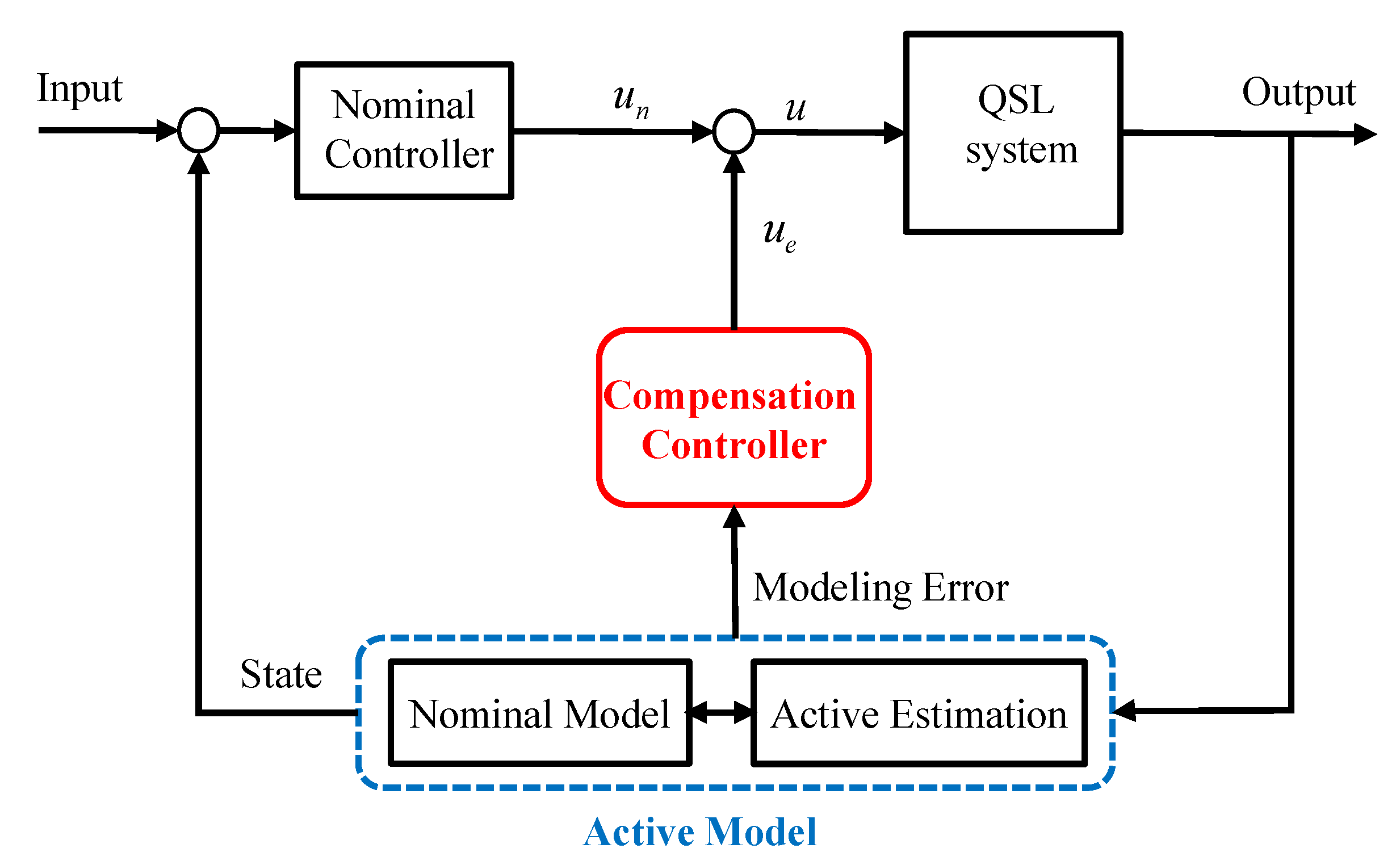
4. Design of Active Model Based Control
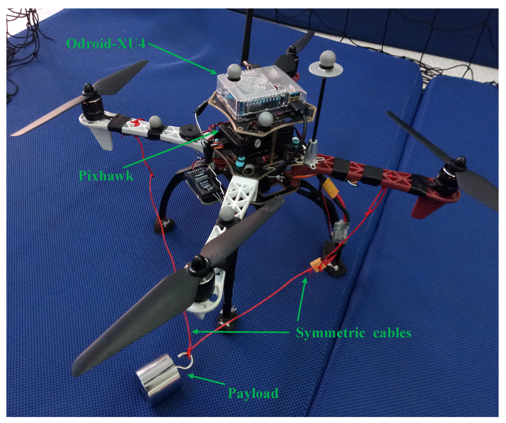
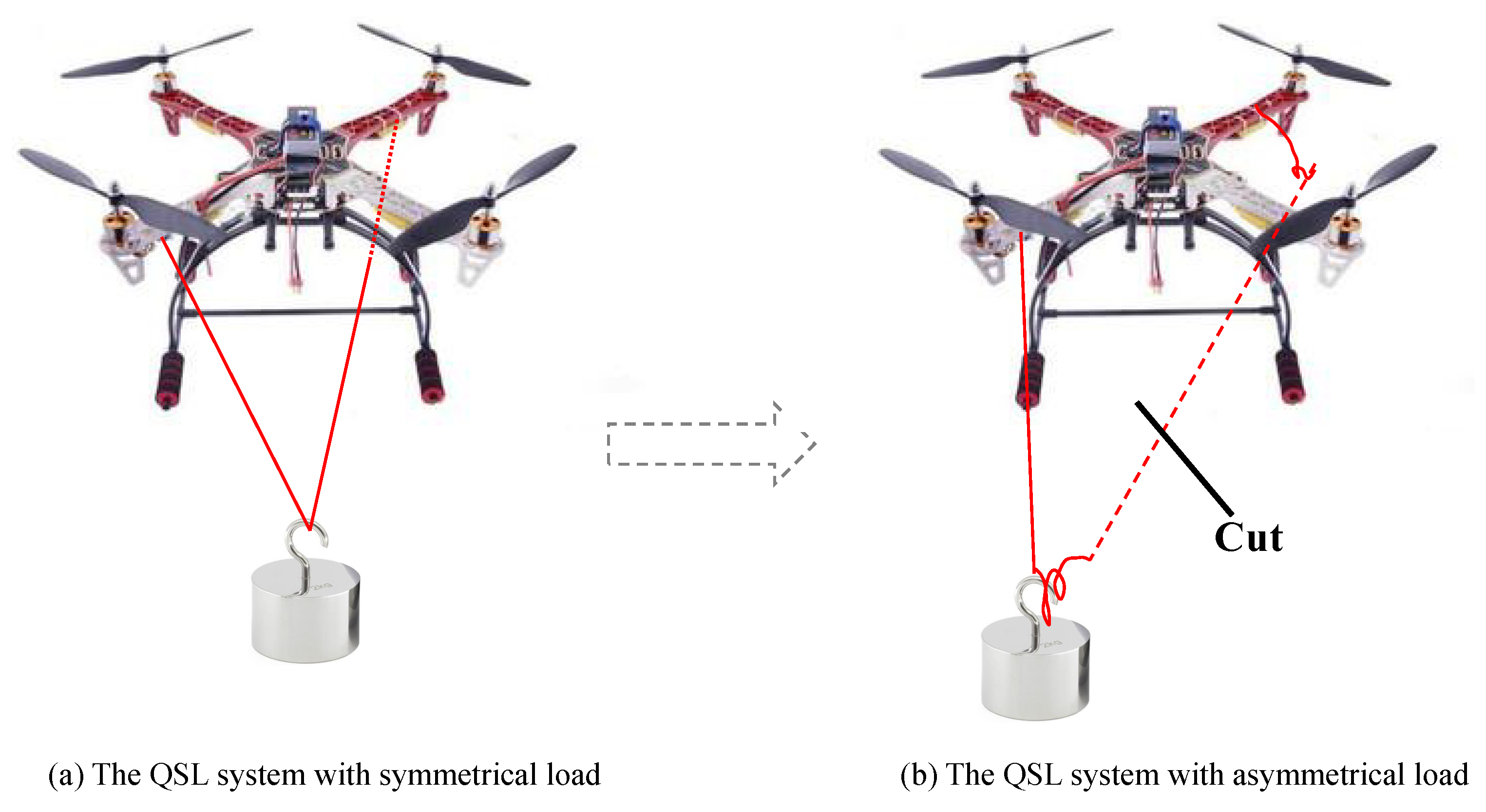
Shown as Figure 1, the active model based control is designed as a complementary enhancement of the normal controller, i.e.,
u = u n + u e
where u is the control input of Equation (12); u n is the nominal control; and u e is the compensation control.
The nominal control is designed according to the reference model of Equation (6), or any other controller which the quadrotor uses already. The compensation control, on the other hand, is designed based on the estimated model error f k . The purpose of the compensation control is to achieve
f t = x ˜ ˙ x ˙ = 0 .
Substituting Equations (6) and (10) into Equation (17), we have
G 0 u + f G 0 u n = 0 .
Substituting Equation (16) into Equation (18) yields
G 0 u e + f = 0 .
To solve Equation (19), the following optimization method [26], i.e., the following cost function with a quadratic form is considered:
u e * = arg min u e Γ k u e Γ k u e = ( G 0 u e + f ^ ) T L 1 ( G 0 u e + f ^ ) + u e T L 2 u e ,
where Γ k is the defined cost function; L 1 , L 2 are positive definite weight matrices, which are set previously; and f ^ is the estimated value of f . In particular, L 1 is an identity matrix. To minimize Γ k u e , we can derive
Γ k u e u e = 0 .
Combing Equations (20) and (21), we can yield
Γ k u e u e = 2 ( G 0 T L 1 G 0 + L 2 ) u e + 2 G 0 T L 1 f ^ .
Therefore, the compensation control input is chosen as:
u e = ( G 0 T L 1 G 0 + L 2 ) 1 G 0 T L 1 f ^ .

5. Experiments

The quadrotor we use to test the proposed scheme is shown in Figure 2. It has the cross X configuration, and a Pixhawk flight controller where the original PID algorithm of Equation (24) is embedded as the normal control [27,28]. The proposed active estimation and enhancement control are implemented on the added controller, i.e., Odroid XU4. The motion states of the quadrotor, shown in Figure 3, are measured by the Qualisys motion capture system [29], and the sampling rate is 200 Hz.
u n = K p e ( k T ) + K i j = 0 k e ( j T ) + K d [ e ( k T ) e ( ( k 1 ) T ) ]
Shown in Figure 3, we use a counterweight as the slung load. Initially, the counterweight is attached to the quadrotor by two symmetrical cables, so the load is aligned along the center of gravity (CoG) of the quadrotor (Figure 3a). The length of each cable is 0.39 m and the mass of the load is 0.5 kg. During the hovering flight, one of the cables is cut abruptly so that the load become asymmetrically attached and will influence the weight balance of the quadrotor (Figure 3b). The active modeling error estimation, the nominal PID control, the active estimation of modeling error, as well as the active-model-based compensation control, are respectively tested with respect to this load change scenario. And the experimental video is available as supplementary material.
Before the experiments, the nominal model of the quadrotor with respect to hovering mode is identified offline by least square method [30,31], and we get the parameters of Equations (3)–(6), i.e.,
M ^ = 1.473 k g g ^ = 9.8 m / s 2 l ^ = 0.225 m I ^ x x = 17 . 195 g · m 2 I ^ y y = 18 . 648 g · m 2 I ^ z z = 22 . 853 g · m 2 k ^ τ = 1.39 × 10 2 g f / ( r a d / m s ) 2 k ^ f = 9.02 × 10 3 N m / ( r a d / m s ) 2 .

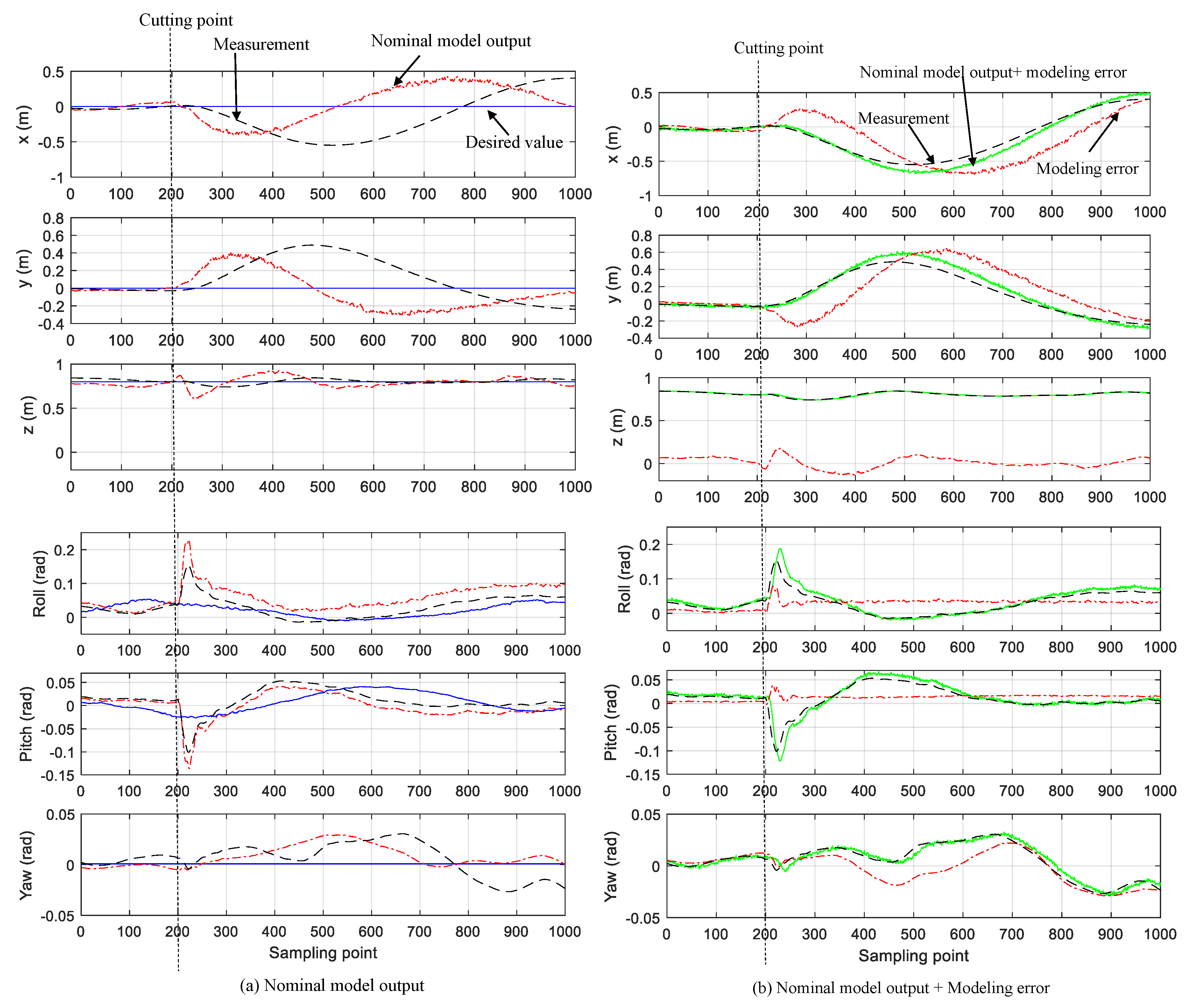
5.1. Experimental Results on Modeling Error Estimation

The experiment is conducted to verify the modeling error estimation technique. The QSL system is in the hovering state controlled by the nominal controller only, while one of the cables is cut abruptly to generate the load change (Figure 3). The experimental results are shown in Figure 4, where the cable is cut at the sampling point of 200.
There are 3 plots in each of the figures of Figure 4a which are, respectively, the desired value, the measurements of the quadrotor motion state, and the nominal model outputs. We can see that the nominal model outputs meet the measurements well before the cut occurring, which indicates that the offline-identified model matched the quadrotor well in the hovering state. After the cutting, the nominal model outputs deviate significantly from the corresponding measurements, which means the model can not describe the load change. Therefore, the real measurements of the quadrotor bias the desire values significantly, which means the quadrotor vibrates clearly after the abrupt change of the load.
Figure 4b demonstrates the performance of the active estimation of modeling error. There are also 3 plots in each figure of Figure 4b, which are the measurements of the motion state, modeling error estimation, and the nominal output + modeling error. We can see that the deviation of the model outputs from the corresponding measurements has been effectively rejected by the proposed active modeling technique.
In order to demonstrate the effectiveness of the active estimation in quantify, we propose the following index [32] to calculate the average errors between two states:
E ¯ = 1 N j = 1 N q j a q j b ,
where j represents sampling point and j = 1 , 2 , 3 , , N ; E ¯ is the average error between q j a and q j b . While q j a are the “normal model output” and the “normal model output + the modeling error” respectively, and q j b is the corresponding measurement, the average errors calculated by Equation (26) are listed in Table 1. We can see that the average position errors have been rejected more than 80% by the active modeling method, and the attitude errors have been rejected more than 58%.

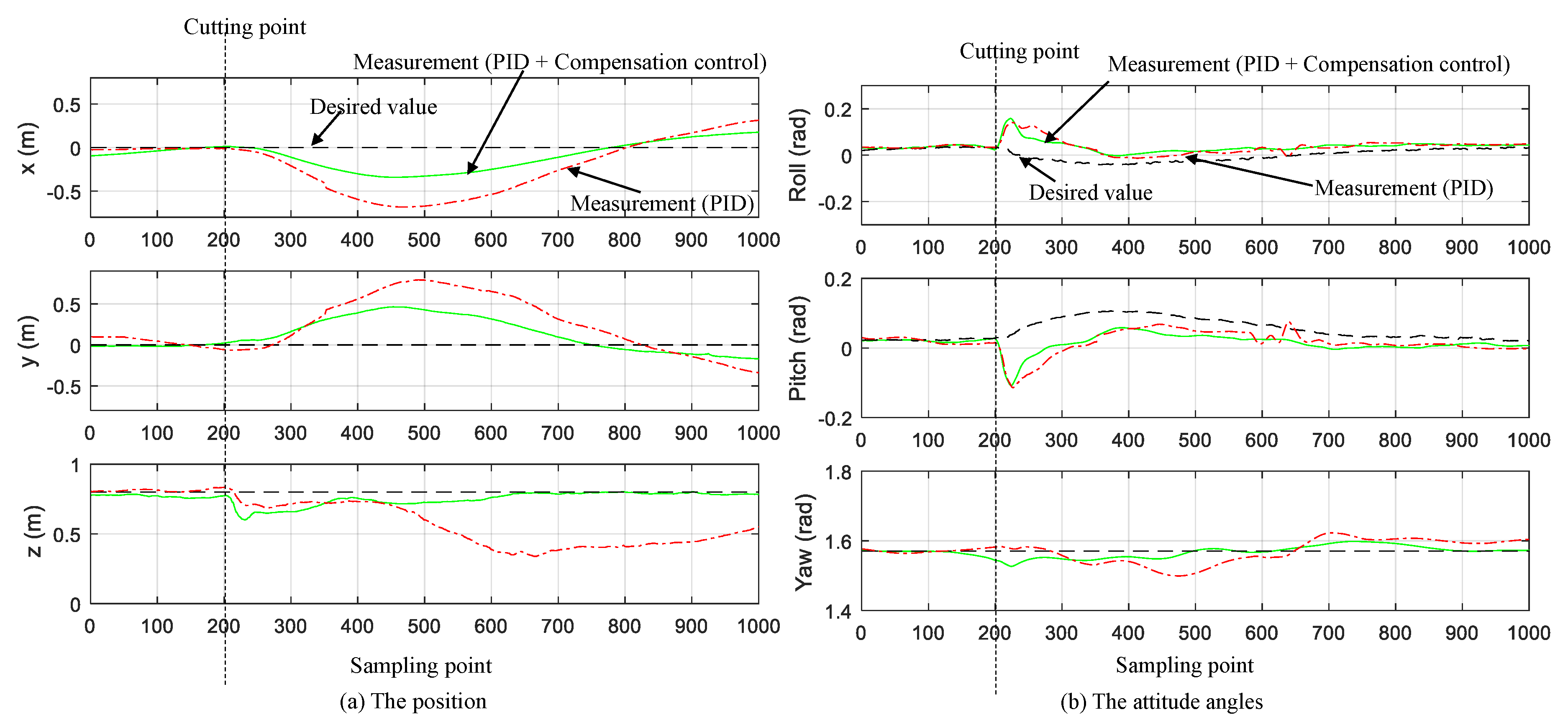
5.2. Experimental Results on the Active-Model-Enhanced Control

Figure 5 demonstrates the control performance with and without the active-model-based enhancement. The compensation control is designed according to Equation (24). There are 2 plots in each figure of Figure 5, which are, respectively, the measurements by “the normal cascade PID control” only, and the measurements by “the normal cascade PID + active-model-based enhancement”. From Figure 5 we can see that after the cable-cutting, the deviations of the measurements by enhanced PID control are much smaller than those by the normal PID control.
While q j a are the motion states under the “normal PID control” and the “enhanced PID control” respectively, and q j b is the corresponding measurement, the average errors of Equation (26) are listed in Table 2. We can see that after the active-modeling-error-based enhancement, the position tracking errors caused by the abrupt load change have been rejected more than 40%, and the attitude errors more than 27%, while being compared with the normal PID control.

6. Conclusions

Active modeling error estimation and the corresponding compensation control scheme have been proposed in this paper. The performance of both the active estimation and enhancement control are verified by experimental flight tests. One of the advantages of this scheme is that the compensation enhances the rejection of the modeling errors in a “decoupled way” with the normal control, namely, the compensation based on the active estimation is completely decoupled with the nominal control, so it may be combined with any normal controls as an enhancement. With its simple structure and less computational algorithm, the proposed scheme may be feasible for a commercial quadrotor to handle payload uncertainties during some real applications.

Supplementary Materials

Supplementary File 1

Author Contributions

Conceptualization, K.Y. and X.L.; methodology, K.Y.; software, K.Y.; validation, X.L., Y.H., L.Y. and J.H.; formal analysis, K.Y. and J.H.; investigation, K.Y. and X.L.; resources, X.L., Y.H., L.Y. and J.H.; data curation, K.Y.; writing—original draft preparation, K.Y.; writing—review and editing, K.Y., X.L., Y.H., L.Y. and J.H.; visualization, X.L.; supervision, J.H.; project administration, X.L. and Y.H.; funding acquisition, Y.H., L.Y. and J.H.

Funding

This work was supported in part by the National Key Research and Development Program of China under Grant 2017YFD0701002, and in part by the National Natural Science Foundation of China under Grant 91848203, U1508208 and 61503369.

Acknowledgments

The authors would like to thank Ning Sun at Nankai University, Zhihong Man at Swinburne University of Technology, the Editor-in-Chief, the Associate Editor, and the anonymous reviewers for their valuable comments for improving this work.

Conflicts of Interest

The authors declare no conflict of interest.

References

  1. Yi, K.; Liang, X.; He, Y.; Yang, L.; Han, J. KF-Based Active Modeling for a Quadrotor Slung Load System. In Proceedings of the 2018 IEEE International Conference on Robotics and Biomimetics (ROBIO), Kuala Lumpur, Malaysia, 12–15 December 2018; pp. 2279–2284. [Google Scholar]
  2. Adams, C.; Potter, J.; Singhose, W. Input-Shaping and Model-Following Control of a Helicopter Carrying a Suspended Load. J. Guid. Control Dyn. 2015, 38, 94–105. [Google Scholar] [CrossRef]
  3. Yi, K.; Gu, F.; Yang, L.; He, Y.; Han, J. Sliding Mode Control for a Quadrotor Slung Load System. In Proceedings of the 2017 36th Chinese Control Conference (CCC), Dalian, China, 26–28 July 2017; pp. 3697–3703. [Google Scholar]
  4. Pizetta, I.H.B.; Brandao, A.S.; Sarcinelli-Filho, M. Control and Obstacle Avoidance for an UAV Carrying a Load in Forestal Environments. In Proceedings of the International Conference on Unmanned Aircraft Systems, Dallas, TX, USA, 12–15 June 2018; pp. 62–67. [Google Scholar]
  5. Liang, X.; Fang, Y.; Sun, N.; Lin, H. Nonlinear Hierarchical Control for Unmanned Quadrotor Transportation Systems. IEEE Trans. Ind. Electron. 2018, 65, 3395–3405. [Google Scholar] [CrossRef]
  6. Goodarzi, F.A.; Lee, D.; Lee, T. Geometric Stabilization of a Quadrotor UAV with a Payload Connected by Flexible Cable. In Proceedings of the American Control Conference, Portland, OR, USA, 4–6 June 2014; pp. 4925–4930. [Google Scholar]
  7. Almeida, M.M.D.; Raffo, G.V. Nonlinear Control of a TiltRotor UAV for Load Transportation. IFAC Papersonline 2015, 48, 232–237. [Google Scholar]
  8. Lee, B.Y.; Hong, S.M.; Yoo, D.W.; Lee, H.I.; Moon, G.H.; Tahk, M.J. Design of a Neural Network Controller for a Slung-Load System Lifted by 1 Quad-Rotor. J. Autom. Control. Eng. 2015, 3, 9–14. [Google Scholar] [CrossRef]
  9. Lee, B.Y.; Lee, H.I.; Yoo, D.W.; Moon, G.H.; Lee, D.Y.; Kim, Y.Y.; Tahk, M.J. Study on Payload Stabilization Method with the Slung-load Transportation System Using a Quad-rotor. In Proceedings of the European Control Conference (ECC), Linz, Austria, 15–17 July 2015; pp. 2097–2102. [Google Scholar]
  10. Jain, R.P.K. Transportation of Cable Suspended Load Using Unmanned Aerial Vehicles: A Real-Time Model Predictive Control Approach. Master’s Thesis, Delft University of Technology, Delft, The Netherlands, 2015. [Google Scholar]
  11. Klausen, K.; Fossen, T.I.; Johansen, T.A. Nonlinear Control of a Multirotor UAV with Suspended Load. In Proceedings of the International Conference on Unmanned Aircraft Systems, Denver, CO, USA, 9–12 June 2015; pp. 176–184. [Google Scholar]
  12. Nicotra, M.M.; Garone, E.; Naldi, R.; Marconi, L. Nested Saturation Control of an UAV Carrying a Suspended Load. In Proceedings of the American Control Conference, Portland, OR, USA, 4–6 June 2014; pp. 3585–3590. [Google Scholar]
  13. Zhou, X.; Liu, R.; Zhang, J.; Zhang, X. Stabilization of a Quadrotor with Uncertain Suspended Load Using Sliding Mode Control. In Proceedings of the ASME International Design Engineering Technical Conferences & Computers and Information in Engineering Conference, Charlotte, NC, USA, 21–24 August 2016. [Google Scholar]
  14. Potter, J.; Singhose, W.; Costelloy, M. Reducing Swing of Model Helicopter Sling Load using Input Shaping. In Proceedings of the IEEE International Conference on Control and Automation, Santiago, Chile, 19–21 December 2011; pp. 348–353. [Google Scholar]
  15. Adams, C.; Potter, J.; Singhose, W. Modeling and Input Shaping Control of a Micro Coaxial Radio-Controlled Helicopter Carrying a Suspended Load. In Proceedings of the International Conference on Control, Automation and Systems, JeJu Island, Korea, 17–21 October 2012; pp. 645–650. [Google Scholar]
  16. Ivler, C.M.; Tischler, M.; Powell, J.D. Cable Angle Feedback Control Systems to Improve Handling Qualities for Helicopters with Slung Loads. In Proceedings of the AIAA Guidance, Navigation, and Control Conference, Portland, OR, USA, 8–11 August 2011. [Google Scholar]
  17. Bisgaard, M.; Courharbo, A.L.; Bendtsen, J. Input Shaping for Helicopter Slung Load Swing Reduction. In Proceedings of the AIAA Guidance, Navigation and Control Conference and Exhibit, Keystone, CO, USA, 21–24 August 2006. [Google Scholar]
  18. Bisgaard, M.; Courharbo, A.L.; Bendtsen, J. Full State Estimation for Helicopter Slung Load System. In Proceedings of the AIAA Guidance, Navigation and Control Conference and Exhibit, Hilton Head Island, SC, USA, 20–23 August 2007. [Google Scholar]
  19. Bisgaard, M.; Bendtsen, J.; Courharbo, A.L. Modelling of Generic Slung Load System. J. Guidance Control Dyn. 2009, 32, 573–585. [Google Scholar] [CrossRef]
  20. Bisgaard, M. Modeling, Estimation, and Control of Helicopter Slung Load System. Ph.D. Thesis, Aalborg University, Aalborg, Denmark, 2008. [Google Scholar]
  21. Bisgaard, M.; Cour-Harbo, A.L.; Bendtsen, J.D. Adaptive Control System for Autonomous Helicopter Slung Load Operations. Control Eng. Pract. 2010, 18, 800–811. [Google Scholar] [CrossRef]
  22. Bisgaard, M.; Cour-Harbo, A.L.; Bendtsen, J.D. Swing Damping for Helicopter Slung Load Systems using Delayed Feedback. In Proceedings of the AIAA Guidance, Navigation, and Control Conference and Exhibit, Chicago, IL, USA, 10–13 August 2009. [Google Scholar]
  23. Bisgaard, M.; Cour-Harbo, A.L.; Johnson, E.N.; Bendtsen, J.D. Vision Aided State Estimator for Helicopter Slung Load System. In Proceedings of the 17th IFAC Symposium On Automatic Control In Aerospace, Toulouse, France, 25–29 June 2007; pp. 425–430. [Google Scholar]
  24. Shi, D.; Wu, Z.; Chou, W. Harmonic Extended State Observer Based Anti-Swing Attitude Control for Quadrotor with Slung Load. Electronics 2018, 7, 83. [Google Scholar] [CrossRef]
  25. Abbeel, P.; Coates, A.; Ng, A.Y. Autonomous Helicopter Aerobatics Through Apprenticeship Learning. Int. J. Rob. Res. 2010, 29, 1608–1639. [Google Scholar] [CrossRef]
  26. Zhang, D.; Zhao, X.; Han, J. Active Model-Based Control for Pneumatic Artificial Muscle. IEEE Trans. Ind. Electron. 2017, 64, 1686–1695. [Google Scholar] [CrossRef] [Green Version]
  27. Dai, B.; He, Y.; Gu, F.; Yang, L.; Han, J.; Xu, W. A Vision-Based Autonomous Aerial Spray System for Precision Agriculture. In Proceedings of the IEEE International Conference on Robotics and Biomimetics, Macau, China, 5–8 December 2017; pp. 507–513. [Google Scholar]
  28. Mellinger, D.; Kumar, V. Minimum Snap Trajectory Generation and Control for Quadrotors. In Proceedings of the IEEE International Conference on Robotics and Automation, Shanghai, China, 9–13 May 2011; pp. 2520–2525. [Google Scholar]
  29. Qualisys Motion Capture System. Available online: https://www.qualisys.com/ (accessed on 12 August 2018).
  30. Reséndiz, V.M.A.; Rivas-Araiza, E.A. System Identification of a Quadrotor in X Configuration from Experimental Data. Res. Comput. Sci. 2016, 118, 77–86. [Google Scholar]
  31. Liu, J.; Shen, X.; Zhao, L. System Identification Theory and MATLAB Simulation; Publishing House of Electronics Industry: Beijing, China, 2013. [Google Scholar]
  32. Sheng, Z.; Xie, S.; Pan, C. Probability and Mathematical Statistics, 4th ed.; Higher Education Press: Beijing, China, 2008. [Google Scholar]
Figure 1. Scheme of the active-model-enhanced control
Electronics 08 00461 g001
Figure 2. The experimental testbed
Electronics 08 00461 g002
Figure 3. The experimental scenario. (a) The quadrotor slung load (QSL) system with symmetrical load; (b) The QSL system with asymmetrical load.
Electronics 08 00461 g003
Figure 4. The performance of the active model error estimation (The measurements (black dashed), the nominal model outputs (red dashdot), the desired values (blue solid), or estimated model errors (red dashdot), and the nominal model + modeling errors (green solid) before and after the load change). (a) Nominal model output; (b) Nominal model output + Modeling error.
Electronics 08 00461 g004
Figure 5. The experimental results. (a) The position; (b) The attitude angles.
Electronics 08 00461 g005
Table 1. The E ¯ of modeling.
State E ¯ of Nominal Model E ¯ of Nominal Model + Active EstimationImprovement
x 0.3276 m 0.0620 m81.07%
y 0.2724 m 0.0507 m81.39%
z 0.0504 m 0.0045 m91.07%
φ 0.0345 rad 0.0092 rad73.33%
θ 0.0151 rad 0.0063 rad58.28%
ψ 0.0136 rad 0.0033 rad75.7%
Table 2. The E ¯ of control.
State E ¯ of Nominal Control E ¯ of Nominal Control + Compensation ControlImprovement
x 0.3304 m 0.1693 m48.76%
y 0.3656 m 0.2062 m43.6%
z 0.2308 m 0.0426 m81.54%
φ 0.0509 rad 0.0336 rad34%
θ 0.0530 rad 0.0387 rad27%
ψ 0.0297 rad 0.0122 rad58.9%

