Abstract
This paper applies modified feedback technology to carry out the exact steady-state and fast transient in a high-performance alternating current (AC) power supply. The presented scheme displays the virtues of a finite-time convergence control (FTCC) and a discrete grey prediction model (DGPM). The FTCC, derived from a terminal sliding-mode (TSM) design principle, can produce the finite system-state convergence time and evade the singularity. It is noteworthy that the chattering/steady-state error around the FTCC may occur because of the overestimated or underestimated uncertainty bound. The DGPM with the bound estimate ability is integrated into the FTCC to cope with internal parameter variations and external load disturbances. The less chattering and steady-state error can be obtained, providing more robust performance in the AC power supply. The combination of the FTCC and the DGPM extends the standard TSM design for the purpose of faster singularity-free convergence, as well as introducing the grey modeling method in the case of a more exact uncertainty estimate. The modified control technology has a high-precision tracking performance and a fast convergent speed. Simulated and experimental results point out that the modified control technology can effectuate low total harmonic distortion (THD) and fast dynamic response in the presence of rectifier loads and abrupt step load changes.
1. Introduction
Alternating current (AC) power supplies have been employed as an important unit for power conversion systems, such as uninterruptible power systems, solar photovoltaic systems, and wind turbine generating systems [1,2]. A high-performance AC power supply should comprise the following: (1) low harmonic distortion for linear/nonlinear loads. The IEEE standard 519-1992 suggests that the voltage total harmonic distortion (THD) is below 5%. (2) As applied to abrupt load changes, the dynamic response with smaller voltage sag and faster transient recovery time. According to IEEE standard 1159-1995, the voltage sag specifies a decrease in RMS (root mean square) voltage/current at the power frequency for durations from 0.5 cycles to one minute. The values of normal voltage sags are between 0.1 and. 0.9 per unit. (3) Nearly zero steady-state tracking errors. Sliding mode control (SMC) can provide the insensitivity to system uncertainties [3,4]; a number of SMCs presented for the AC power supply have been performed [5,6,7]. A fixed switching frequency sliding mode is applied to uninterruptible power supplies. The standard SMC is employed and the distorted output-voltage yields under nonlinear loading [5]. To enhance the system performance of the AC power supply, a standard SMC with an adaptive method is designed. Although the good performance in the steady-state and the transient can be obtained, the presented algorithm is complicated [6]. The combination of the standard SMC and the sensor number reduction is developed for three-phase inverters. The sophisticated hardware design is improved, but the chattering phenomenon still exists [7]. As previously mentioned, these standard SMC approaches display linear sliding surfaces, leading to a non-finite-time convergence. To raise the convergence speed, a finite-time convergence control (FTCC) is used with the nonlinear sliding surface in this paper. By appropriately designing the FTTC parameters, the system states will reach the sliding surface and converge to the equilibrium within a finite time, yielding a stable closed-loop system [8,9,10]. Nevertheless, the chattering will appear in the AC power supply output if a highly nonlinear load is applied. The chattering brings a high harmonic distortion and thermal breakdown in transistors, thus leading to instability and unreliability of the AC power supply system. Several approaches, such as observer methodology and adaptive control, for removing the chattering have strived to estimate the bounds of system uncertainties. These approaches indeed reduce the chattering, but the control designs incur long tracking times [11,12,13]. Since the 1980s, the discrete grey prediction model (DGPM) has tempted broad research interests because of its efficient and fast computation [14,15]. The DGPM just needs a few sampled data to depict the tendency of the time-series data from the anterior system dynamics, acquiring the dependable and acceptable forecast accuracy [16,17,18,19]. The DGPM is thus employed to lessen the chattering when the dynamic system with uncertainty bounds is overestimated. Using the modified control technology, the tracking errors can be minimized and the AC power supply creates the low distorted harmonics, the fast dynamics, the chattering reduction, and the steady-state error mitigation. Though the eventual performance results of the modified control system do not top the THD results of recent former research, the reinforcement of the FTCC methodology has produced a robust and more exact estimate of the uncertainty bounds. As can be noticed, the presented association of the FTCC and the DGPM contributes to a closed-loop feedback AC power supply with the small steady-state distortion and fast response under different load cases. The competence of the modified control technology is ratified via a digital implementation on a digital signal processing (DSP)-based AC power supply and the modified control system is also simulated using MATLAB/SIMULINK software.
2. System Modeling
Figure 1 illustrates the system block diagram of the AC power supply, which comprises transistor switches, an LC (inductor capacitor) filter, and a load. The denotes the output-voltage, stands for the desired sine wave, is the voltage error, and represents the load. Using a high switching frequency, the AC power supply and its PWM (pulse width modulation) are frequently modeled as a constant gain . Therefore, the error dynamics can be formulated as
where represents , stands for , is , and signifies the system uncertainty. It is noteworthy that the component values for the LC filter of the AC power supply can be chosen by the suggested methods as follows [20,21,22]. (i) Choose the switching frequency [21,22]—to decrease the size of the filter, a high enough switching frequency between 3 kHz to 15 kHz is frequently selected for IGBT (insulated gate bipolar transistor) switches. (ii) Choose a factor related to the cut-off frequency of the LC filter [20]—if the factor is lager, there is a great degradation and a small magnification in the switching frequency and the fundamental frequency, respectively. The minimum of the factor can be computed while the modulation value is recommended below 0.95. (iii) Choose a factor related to both switching frequency and inductor ripple current [22]—the inductor ripple current from 20% to 40% is an advisable range. Then, from (8), (20), (25), and (26) in the work of [20], the factor can be selected, and L and C component values are computed.
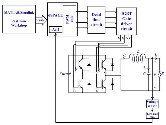
Figure 1.
A control structure of an alternating current (AC) power supply system. PWM—pulse width modulation; IGBT—insulated gate bipolar transistor.
The control signal in (1) has to be designed adequately, so as to coerce and to zero. Namely, the FTCC impels the system tracking behavior to converge to the origin in a finite time. Nevertheless, the load condition of the AC power supply may be a sudden large step change or a severe nonlinearity, the FTCC system effortlessly has the chattering or steady-state error, incurring in an aberrant tracking. As described in the introduction section, considerable studies have been conducted to reveal a diminution in the amount of the chattering or to make the steady-state error as small as possible. Recently, the practical application of the prediction methods has swiftly become a hot topic in both engineering and science. On the basis of such a prompting, it will be a good notion to introduce predictive modeling techniques into the FTCC design, affording better system robustness and an alternative reference to researchers interested in AC power supply applications. The FTCC with the DGPM assistance is presented to enhance the classic FTCC for the chattering/steady-state error mitigation providing a more exact tracking. The AC power supply system using this modified control technology allows a higher performance AC output-voltage in response to uncertain perturbations.
3. Control Technology Design
For the tracking error dynamics (1), the terminal sliding function is written as
where and .
The and are reached within a finite time. The control law can be designed to insure the subsistence of the TSM as follows:
with the items of and as follows:
where the is the equivalent control constituent and supervises the unperturbed dynamics, thus letting and . stands for the sliding control constituent with the disturbance rejection and, in consequence, the state behavior can arrive at the sliding mode and accomplish a finite system-state convergence time. However, there are the following problems occurring in the equivalent control constituent. (1) containing the may induce a singularity if , while and . The singularity leads to an unbounded control signal and the stability of the feedback system. (2) As a matter of fact, may generate an imaginary number under the constraint .
To subdue the singularity problem, the following FTCC is formed as
Then, a sliding-mode reaching equation is utilized; thereupon, the control law is restated as
with
where represents the equivalent control without the singularity that conducts the system dynamics. represents the sliding control with the fast convergence, and can arrest the influence of system uncertainties. The control law expressed in (7) is modified by the annexation of the DGPM (), which can relieve the chattering in the AC power supply system. The modeling operation of the DGPM is illustrated in the following:
Step 1: Input the prime data
The prime data sequence is presumed as
where is the number of the recorded data.
Step 2: Applying the mapping generating operation (MGO)
The employment of the MGO can map the prime data sequence onto the non-negative sequence because of the positive or negative data sequence existing in the control system:
The relatedness and can be described as
Step 3: Applying the accumulated generating operation (AGO)
The first-order AGO sequence can be acquired by using the AGO on as follows:
Step 4: Grey model
By employing the accumulated data sequence, , a first-order ordinary differential grey model is established as
where indicates the developing coefficient and is the grey input.
In order to attain the grey background value, the data sequence is formulated by employing the following MEAN generating operation to the .
While the sampling interval is one unit, the differential of the generating sequence can be expressed as
In order to decide the values of and , (16) can be written as
where , , and .
By the least-squares method, the estimated parameters and can be solved as
Substituting (18) into the differential equation, the count of the forecasted value yields
Step 5: Applying the inverse accumulated generating operation (IAGO)
The data sequence can be obtained by applying the IAGO on the below.
Step 6: Applying the inverse mapping generating operation (IMGO)
By using the IMGO, the forecasted value of the prime data sequence can be stated as
where can eschew a negative sequence . Thus, the control law of (13) is re-described as
where the annexed compensation part, that is, discrete grey prediction control, , is capable mitigating the phenomenon of the chattering.
where indicates a constant, connotes the forecasted value of , and is the system boundary.
4. Simulation and Experimental Results
The performance of the presented AC power supply is investigated through the simulations and experiments. The system parameters of the AC power supply are offered in Table 1. Figure 2 and Figure 3 plot the simulated waveforms under a step change in load (from 12 ohm to no load) obtained using the modified control technology and the classic FTCC, respectively. Expectably, the modified control technology achieves a fast and an exact trajectory tracking, that is, the swift transient response of the output-voltage can be acquired and there is approximately no output-voltage swell at the firing angle. Reversely, the classic finite-time convergence controlled AC power supply system reveals an observable output-voltage swell at the firing angle. To examine a stricter situation (abrupt load change from no load to 12 ohm), the simulated waveforms obtained using the modified technology and the classic FTCC are shown in Figure 4 and Figure 5, respectively. Contrary to the classic FTCC, the modified control technology displays a slight voltage slump and a swift output-voltage recovery, thus corroborating the finite-time reachable sliding surface. Because of the effectual compensation of the DGPM, after a tiny instant voltage slump (3 Vrms), the output voltage with the modified control technology can be reverted to the sinusoidal reference voltage; nevertheless, the classic FTCC brings a great voltage slump (32 Vrms). Figure 6 depicts that the modified control technology is capable of enduring the random variations of the filter parameters L and C from 20% to 150% and 20% to 150%, respectively, of the nominal values under a resistive load of 12 ohm. The classic FTCC shown in Figure 7 generates the sensitivity with conspicuous wobble to the LC variation, which degrades the system’s robustness. The simulated comparison of the voltage slump and the %THD under a step loading and an LC variation is offered in Table 2. Figure 8 shows the different load situations used in the experiments, in order to test the transient and steady-state behavior of the AC power supply. Figure 9 and Figure 10 illustrate the experimental waveforms obtained using the modified control technology and the classic FTCC in the presence of step load changes (from no load to full load), respectively. Figure 9 exhibits a petty voltage slump with a swift retrieval time, but the classic FTCC system revealed in Figure 10 has a poor transient and the recovery of the voltage slump takes a long time. The output voltage of the modified control system can reach 110 V RMS sine reference in the back of the 5 Vrms puny voltage slump. Nevertheless, there is a nearly 30 Vrms output voltage slump in the classic FTCC system, producing a disappointing transient response. When a full resistive load of 12 ohm is applied, the system performance in response to the random variations (20%~150% of the nominal value) of the filter parameters is also explored. The experimental output voltage shown in Figure 11 obtained using the modified control technology gives the tolerable ability of the larger parametric variations. For the classic FTCC, from the start to the termination of the waveform, an output voltage distortion shown in Figure 12 is seen with the sensitivity. The experimental result of the modified controlled AC power supply under a rectifier load (a 270 μF capacitor and a 35 Ω resistor in parallel) is displayed in Figure 13. Though the load current shows high spikes, the distortion of the output-voltage is tiny (voltage %THD = 1.35%). Inversely, the results yielded by the classic finite-time convergence controlled AC power supply under the identical load situation are illustrated in the Figure 14 with a severely distorted waveform (voltage %THD = 8.92%). Table 3 compares the experimental dissimilarity between the modified control technology and the classic FTCC. The experimental tracking errors of the modified control technology, traditional (standard) SMC, and improved SMC are provided in Figure 15. The modified controlled system creates a swift convergence to the origin in a short time and is nearly free of oscillation, as compared with the traditional SMC and the improved SMC. Really, a superior tracking preciseness, a minor harmonic distortion, and a quicker convergence speed were obtained by the modified control technology, which is suitable for the use of the AC power supply. In addition, the classic FTCC law in (3) contains the equivalent control term with the occurrence of the singularity, and the sliding control term with the phenomenon of the chattering. The singularity can be solved by using the modified control technology shown in (8); nevertheless, the parameter that exists in (5) is frequently more than or equal to the interference . The sliding control term of the classic FTCC is replaced by (9) and (23). Under the circumstance of the unknown upper bound of the parameter uncertainties and the external disturbances, the feedback gain of the over-conservatism may generate a large chattering in the classic FTCC. To reduce the gain magnitude and the chattering that exists in the sliding control term, the compensation of (23) can be aroused once overruns the boundary layer width. The feedback gain shown in (9) of the over-conservatism in the modified control technology is divided into two terms, containing the sliding control term and DGPM compensator. The gain magnitude of the modified control technology will become smaller than that of the classic FTCC if the upper bound of the parameter uncertainties and the external disturbances is unknown. Thereby, a robust system performance with reduced chattering in the face of high system uncertainties can be yielded by using the modified control technology. A brief summary of the simulated and experimental results is given to expound the dissimilitude between the modified control technology and the classic FTCC. In practice, the classic FTCC switching gain is proportional to the perturbation upper bound/system uncertainty. The greater switching gain endeavors to stabilize the classic FTCC system if the stern parametric uncertainties and external perturbations transpire. This may bring an undesirable acute chattering. So, the DGPM attempts to adjust the switching gain well, displaying moderation of the chattering and reinforcement of the system performance.

Table 1.
System parameters. DC—direct current.
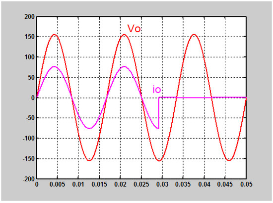
Figure 2.
Simulated waveforms under the load suddenly turn off for the modified control technology (50 V/div; 10 A/div).
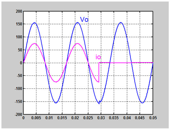
Figure 3.
Simulated waveforms under the load suddenly turn off for the classic finite-time convergence control (FTCC) (50 V/div; 10 A/div).
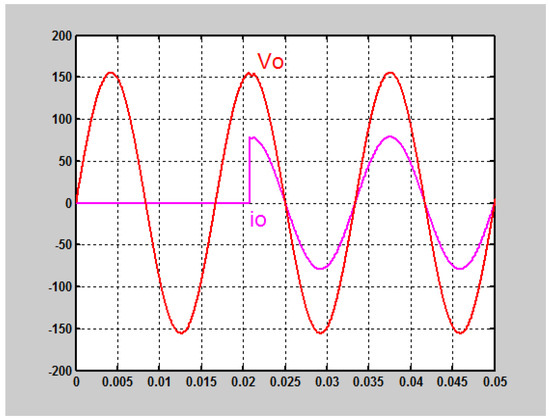
Figure 4.
Simulated waveforms in response to the load suddenly turn on for the modified control technology (50 V/div; 10 A/div).
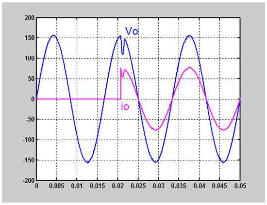
Figure 5.
Simulated waveforms in response to the load suddenly turn on for the classic FTCC (50 V/div 10 A/div).
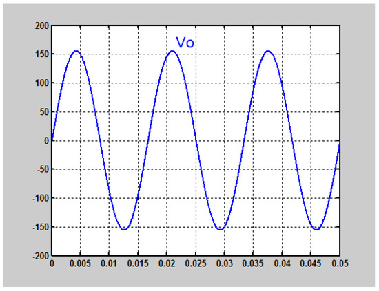
Figure 6.
Simulated waveforms in response to the inductor capacitor (LC) variation for the modified control technology (50 V/div).
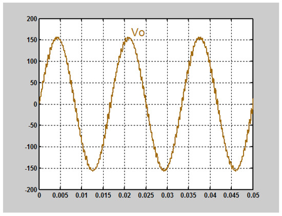
Figure 7.
Simulated waveforms in response to the LC variation for the classic FTCC (50 V/div).
Table 2.
Simulated output-voltage slump and voltage total harmonic distortion (THD) under a step loading and an inductor capacitor (LC) variation. FTCC—finite-time convergence control.
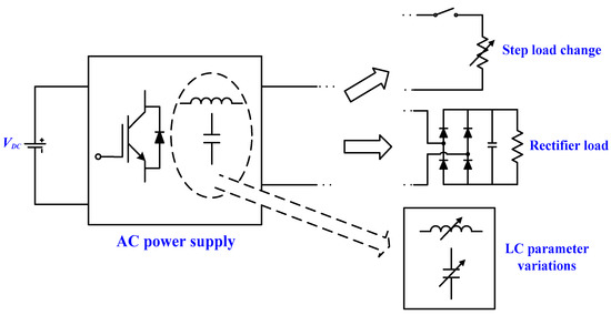
Figure 8.
Experimental tests under different load situations.
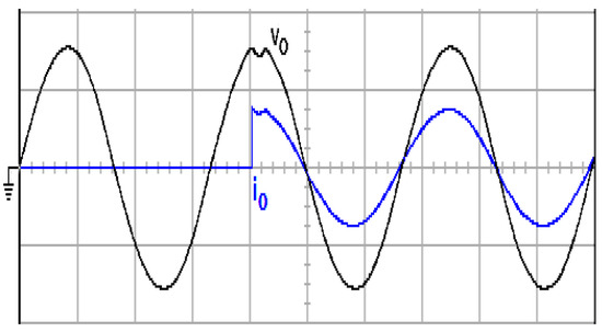
Figure 9.
Experimental waveform under a step change in load for the modified control technology (100 V/div; 20 A/div; 5 ms/div).
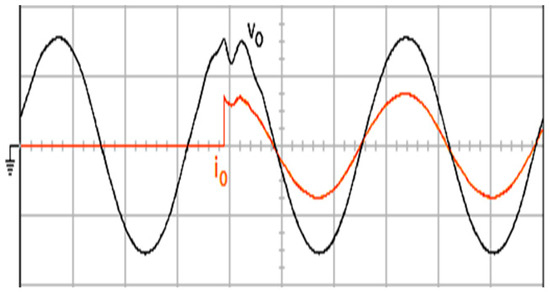
Figure 10.
Experimental waveforms under a step change in load for classic FTCC (100 V/div; 20 A/div; 5 ms/div).
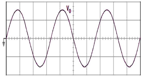
Figure 11.
Experimental waveform under a LC variation for the modified control technology (100 V/div; 5 ms/div).
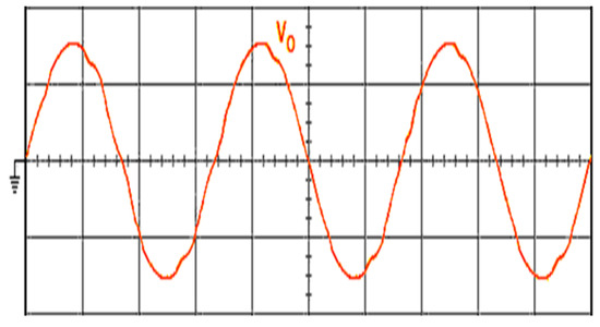
Figure 12.
Experimental waveform under an LC variation for the classic FTCC (100 V/div; 5 ms/div).
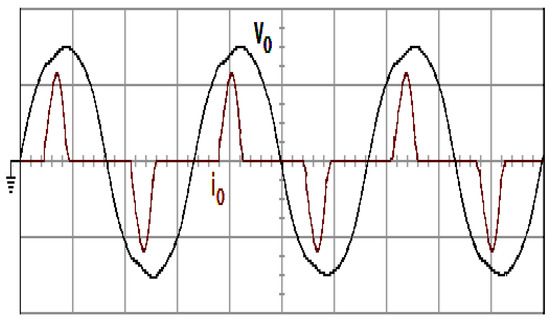
Figure 13.
Experimental waveform under a rectifier load for the modified control technology (100 V/div; 25 A/div; 5 ms/div).
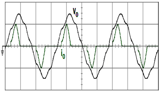
Figure 14.
Experimental waveform under a rectifier load for the classic FTCC (100 V/div; 25 A/div; 5 ms/div).
Table 3.
Experimental output-voltage slump and voltage THD under a step loading and a rectifier load.
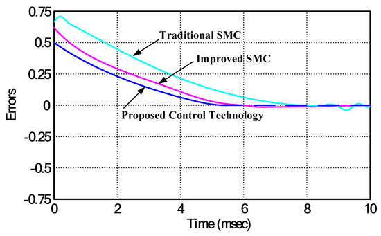
Figure 15.
A comparison of tracking errors. SMC—sliding mode control.
5. Discussion
The modified control technology has been proposed for chattering mitigation, steady-state error moderation, and larger perturbation rejection, thus furnishing a good system performance. Nevertheless, for the purpose of the future research, we have reviewed the wide literature in other robust approaches (such as H-infinity controller, mu-synthesis method, and game-theoretic strategy) and high-order SMC (HOSMC) as follows. A discrete-time H-infinity controller is proposed for uninterruptible power supply systems to achieve a nearly zero steady-state error and a mitigate output-voltage distortion caused by non-linear loads. However, this controller is in need of the sophisticated algorithm [23]. Consolidating a mu-synthesis method into the H-infinity controller has attempted to control the islanded micro-grid so that the effects of the parametric uncertainties and external perturbations can be minimized. The digital realization of the mu-synthesis is complex and the resulting waveform yields a conspicuous harmonic distortion, particularly in the strong non-linearity [24]. A game-theoretic strategy is developed for the control of DC (direct current) microgrids, oppressing the harmonic emergence. Although this strategy reveals a good transient and steady state in the face of an abrupt load change and a non-linear load, it is strongly dependent on the exactness of the plant parameters [25]. The traditional (standard) SMC with a linear sliding surface of a single-phase inverter is investigated and scarcely distorts the output-voltage under a linear load. However, the traditional SMC has a long convergence time and chattering effect [26]. The combination of a proportional-resonant and a traditional sliding surface is suggested to improve the transience in the single-phase inverter. The transient behavior can be enhanced, but this methodology results in steady-state errors [27]. The HOSMC approaches are thus used well to control the AC power supply related systems. A grid connected wind system is presented by the multiple-input multiple-output (MIMO) HOSMC, thus regulating the active and reactive powers. This method generates some satisfactory profits, such as the strong robustness to the uncertain perturbations, the mitigation of the chattering, and the finite time convergence of the system states [28]. A backstepping HOSMC strategy is developed for the grid-connected distributed generation (DG) units. It can regulate the inverter output currents and offer the sinusoidal balanced currents to the grid so that the good performance of the distributed generation unit can be obtained in the presence of system uncertainties [29]. A HOSM observer is introduced into the control design of the AC power supply for the sake of rejecting the parametric variations, complex nonlinearities, and external perturbations. The criterion-based Lyapunov function has sternly vouched for the system stability and the virtue of the HOSM observer [30]. As described above, the HOSMC sustains the primordial robustness of the traditional SMC, and simultaneously produces a minor chattering and a preferable convergence precision. Consequently, the HOSMC approaches will stimulate further investigations following this paper in the AC power supply related areas.
6. Conclusions
In this paper, the FTCC with DGPM to design an AC power supply to improve the transient and steady-state behaviors is reported. The FTCC maintains the robustness of the traditional SMC and yields the finite-time convergence of the system state. The employment of the DGPM can estimate the upper bound of the parametric uncertainties and the external perturbations, relieving the overcautious design of the FTCC. The problem of chattering occurring in the FTCC can be solved as a result of the diminution of the overcautious switching gain that enhances the system performance. The modified control technology thus possesses the reachable sliding surface within a finite time, the closed-loop asymptotic stability, and the finite-time convergence to the zero of the tracking errors. On the basis of the theoretic derivation and analysis, simulations, and experimental results, the potency of the modified control technology is successfully attested and very becoming for the use of the single-phase AC power supply. On the other hand, the modified control technology will also offer exciting opportunities to be applied in other circuit structures (such as a high-step-up DC–DC converter, an LED driver, and an online insulation fault detection circuit) [31,32,33], thus yielding more contributions towards future work.
Author Contributions
E.-C.C. conceived and designed the circuit and developed the methodology. S.-C.Y. and R.-C.W. prepared software resources and set up simulation software. E.-C.C. performed circuit simulations. E.-C.C. carried out the prototype power supply and measured, as well as analyzed, experimental results. E.-C.C. wrote the paper and revised it for submission.
Funding
This research was funded by Ministry of Science and Technology of Taiwan, R.O.C., grant number MOST 107-2221-E-214-006.
Acknowledgments
The authors gratefully acknowledge the financial support of the Ministry of Science and Technology of Taiwan, R.O.C., under project number MOST 107-2221-E-214-006.
Conflicts of Interest
The author declares that there is no conflict of interest regarding the publication of this article.
References
- Wilamowski, B.M.; Irwin, J.D. Power Electronics and Motor Drives; CRC Press: Boca Raton, FL, USA, 2011. [Google Scholar]
- Lu, N.J.; Yang, S.F.; Tang, Y. Ripple Current Reduction for Fuel-Cell-Powered Single-Phase Uninterruptible Power Supplies. IEEE Trans. Ind. Electron. 2017, 64, 6607–6617. [Google Scholar] [CrossRef]
- Vaidyanathan, S.; Lien, C.H. Applications of Sliding Mode Control in Science and Engineering; Springer: New York, NY, USA, 2017. [Google Scholar]
- LWu, G.; Shi, P.; Su, X.J. Sliding Mode Control of Uncertain Parameter-Switching Hybrid Systems; Wiley: New York, NY, USA, 2014. [Google Scholar]
- Pichan, M.; Rastegar, H. Sliding-Mode Control of Four-Leg Inverter with Fixed Switching Frequency for Uninterruptible Power Supply Applications. IEEE Trans. Ind. Electron. 2017, 64, 6805–6814. [Google Scholar] [CrossRef]
- Gautam, A.R.; Gourav, K.; Guerrero, J.M.; Fulwani, D.M. Ripple Mitigation with Improved Line-Load Transients Response in a Two-Stage DC–DC–AC Converter: Adaptive SMC Approach. IEEE Trans. Ind. Electron. 2018, 65, 3125–3135. [Google Scholar] [CrossRef]
- Altin, N.; Ozdemir, S.; Komurcugil, H.; Sefa, I. Sliding-Mode Control in Natural Frame with Reduced Number of Sensors for Three-Phase Grid-TiedLCL-Interfaced Inverters. IEEE Trans. Ind. Electron. 2019, 66, 2903–2913. [Google Scholar] [CrossRef]
- Lu, K.F.; Xia, Y.Q.; Yu, C.M.; Liu, H.L. Finite-Time Tracking Control of Rigid Spacecraft Under Actuator Saturations and Faults. IEEE Trans. Autom. Sci. Eng. 2016, 13, 368–381. [Google Scholar] [CrossRef]
- Hussian, A.; Zhao, X.D.; Zong, G.D. Finite-Time Exact Tracking Control for a Class of Non-linear Dynamical Systems. IET Control Theory Appl. 2017, 11, 2020–2027. [Google Scholar] [CrossRef]
- Golestani, M.; Mobayen, S.; Tchier, F. Adaptive Finite-Time Tracking Control of Uncertain Non-linear n-Order Systems with Unmatched Uncertainties. IET Control Theory Appl. 2016, 10, 1675–1683. [Google Scholar] [CrossRef]
- Peltoniemi, P.; Nuutinen, P.; Pyrhonen, J. Observer-Based Output Voltage Control for DC Power Distribution Purposes. IEEE Trans. Power Electron. 2013, 28, 1914–1926. [Google Scholar] [CrossRef]
- Wu, X.B.; Liu, Q.; Zhao, M.L.; Chen, M.Y. Monolithic Quasi-Sliding-Mode Controller for SIDO Buck Converter with a Self-Adaptive Free-wheeling Current Level. J. Semicond. 2013, 34, 1–7. [Google Scholar] [CrossRef]
- Shen, L.; Lu, D.D.; Li, C. Adaptive Sliding Mode Control Method for DC-DC Converters. IET Power Electron. 2015, 8, 1723–1732. [Google Scholar] [CrossRef]
- Liu, S.F.; Lin, Y. Advances in Grey Systems Research; Springer: Heidelberg/Berlin, Germany, 2010. [Google Scholar]
- Deng, J.L. Introduction to grey system theory. J. Grey Syst. 1989, 1, 1–24. [Google Scholar]
- Wang, M.H.; Tsai, H.H. Fuel cell fault forecasting system using grey and extension theories. IET Renew. Power Gener. 2012, 6, 373–380. [Google Scholar] [CrossRef]
- Wang, M.D.; Wang, X.K.; Su, X.J.; Li, X.Y.; Yang, Y.H. Generator governing system based on grey prediction and extension control. IET Gener. Transm. Distrib. 2017, 11, 3776–3782. [Google Scholar] [CrossRef]
- Truong, D.Q.; Ahn, K.K.; Trung, N.T. Design of An Advanced Time Delay Measurement and A Smart Adaptive Unequal Interval Grey Predictor for Real-Time Nonlinear Control Systems. IEEE Trans. Ind. Electron. 2013, 60, 4574–4589. [Google Scholar] [CrossRef]
- Samet, H.; Mojallal, A. Enhancement of Electric ARC Furnace Reactive Power Compensation Using Grey-Markov Prediction Method. IET Gener. Transm. Distrib. 2014, 8, 1626–1636. [Google Scholar] [CrossRef]
- Ahmad, A.A.; Abrishamifar, A.; Farzi, M. A New Design Procedure for Output LC Filter of Single Phase Inverters. In Proceedings of the International Conference Power Electronics and Intelligent Transportation System, Shenzhen, China, 13–14 November 2010; pp. 86–91. [Google Scholar]
- Dahono, P.A.; Purwadi, A.; Qamaruzzaman. An LC filter Design Method for Single-Phase PWM Inverters. In Proceedings of the International Conference Power Electronics and Drive Systems, Singapore, 21–24 February 1995; pp. 571–576. [Google Scholar]
- Kim, H.S.; Sul, S.K. A Novel Filter Design for Output LC Filters of PWM Inverters. J. Power Electron. 2011, 11, 74–81. [Google Scholar] [CrossRef]
- Darvishzadeh, S.; Rahmati, A.; Abrishamifar, A. Comparative Study of Different Switching Surfaces for Sliding Mode Control of a 40 kVA Single-phase UPS Inverter. Int. J. Comput. Electr. Eng. 2012, 4, 933–936. [Google Scholar] [CrossRef]
- Aamir, M.; Kalwar, K.A.; Mekhilef, S. Proportional-Resonant and Slide Mode Control for Single-Phase UPS Inverter. Electr. Power Compon. Syst. 2017, 45, 11–21. [Google Scholar] [CrossRef]
- Ribas, S.P.; Maccari, L.A.; Pinheiro, H.; Oliveira, R.C.; Montagner, V.F. Design and Implementation of a Discrete-time H-infinity Controller for Uninterruptible Power Supply Systems. IET Power Electron. 2014, 7, 2233–2241. [Google Scholar] [CrossRef]
- Bevrani, H.; Feizi, M.R.; Ataee, S. Robust Frequency Control in an Islanded Microgrid: H-infinity and Mu-Synthesis Approaches. IEEE Trans. Smart Grid 2016, 7, 706–717. [Google Scholar] [CrossRef]
- Ekneligoda, N.C.; Weaver, W.W. Game-Theoretic Cold-Start Transient Optimization in DC Microgrids. IEEE Trans. Ind. Electron. 2014, 61, 6681–6690. [Google Scholar] [CrossRef]
- Valenciaga, F.; Fernandez, R.D. Multiple-Input–Multiple-Output High-Order Sliding Mode Control for a Permanent Magnet Synchronous Generator Wind-Based System with Grid Support Capabilities. IET Renew. Power Gener. 2015, 9, 925–934. [Google Scholar] [CrossRef]
- Dehkordi, N.M.; Sadati, N.; Hamzeh, M. A Robust Backstepping High-Order Sliding Mode Control Strategy for Grid-Connected DG Units with Harmonic/Interharmonic Current Compensation Capability. IEEE Trans. Sustain. Energy 2017, 8, 561–572. [Google Scholar] [CrossRef]
- Chen, D.; Jun, Y.; Wang, Z.; Li, S.H. Universal Active Disturbance Rejection Control for Non-linear Systems with Multiple Disturbances via a High-Order Sliding Mode Observer. IET Control Theory Appl. 2017, 11, 1194–1204. [Google Scholar]
- Cheng, C.A.; Cheng, H.L.; Chang, C.H.; Chang, E.C.; Yang, F.L. Design and Implementation of a Novel High-Step-Up DC-DC Converter. Appl. Mech. Mater. 2013, 284–287, 2498–2501. [Google Scholar]
- Cheng, C.A.; Chang, E.C.; Tseng, C.S.; Chung, T.Y. A Novel High-Power-Factor LED-Lamp Driver Based on a Single-Stage Power Conversion. In Proceedings of the 2014 International Symposium on Computer, Consumer and Control, Taichung, Taiwan, 10–12 June 2014; pp. 1287–1290. [Google Scholar]
- Liu, Y.C.; Chang, E.C.; Lin, Y.L.; Lin, C.Y. A Novel Online Insulation Fault Detection Circuit for DC Power Supply Systems. Int. J. Smart Grid Clean Energy 2018, 7, 64–73. [Google Scholar] [CrossRef]
© 2019 by the authors. Licensee MDPI, Basel, Switzerland. This article is an open access article distributed under the terms and conditions of the Creative Commons Attribution (CC BY) license (http://creativecommons.org/licenses/by/4.0/).