Abstract
In this paper, the concept of a forward balancing technique fed by a buck converter for lithium-based batteries in Electrical Vehicle (EV) applications is investigated. The proposed active topology equalizes eight cells in a series in a battery pack, by using a forward converter for each battery pack and the whole battery packs, using a buck converter. The battery bank consists of four battery packs, which are in series. Therefore, the proposed system will equalize 32 cells in series. In this paper, the proposed circuit employs a single transistor used in a Zero Voltage Switch (ZVS) for the forward converter. In practice, this means a capacitor in parallel with the switch at the same time a demagnetizing of the transformer is obtained. The circuit realizes a low Electromagnetic Interference (EMI) and reduces ringing. To overcome the problem of many pins on a coil former, the transformer secondary windings are made by using hairpin winding, on a ring core. It permits, e.g., having eight secondaries and uniform output voltages. Each secondary winding is made by two hairpin turns using two zero-Ohm resistors in series. The proposed topology has less components and circuitry, and it can equalize multiple battery packs by using a single buck converter and several forward converters for each battery pack. Experimental and simulation results are performed to verify the viability of the proposed topology.
1. Introduction
Notwithstanding the evidence that traditional fuel such as petrol, gasoline, and diesel is necessitated in order to supply automobiles, the source of fossil fuels is limited and decreasing rapidly, and it will be depleted in the future [1,2,3,4]. Furthermore, the world is becoming opposed to incomparable problems such as global warming and sea level rising. Therefore, the demand for electrical vehicles is increasing [5]. They can achieve low pollution and low noise. In electrical vehicles, the cost of the batteries is often more than 50% of the vehicle. As a consequence, batteries with a longer life cycle are desired. Many types of batteries have been proposed for electrical vehicles during the last few decades such as lead acid, nickel-cadmium, lithium-ion (Li-ion), and lithium iron phosphate (LiFePO4) batteries. The Lead acid battery is cost effective for short ranges. However, higher weight, higher volume, and low density are the disadvantages of these batteries [6]. In nickel metal hydride batteries (NiMH), a high discharge rate and a long life time are their advantages, but low energy density and low efficiency are their disadvantages. Lithium ion batteries have an improved energy density and have a long life time as compared to other types [7]. They have the greatest electrochemical potential and provide higher energy per weight.
Currently, lithium-based batteries are the most common electrical energy storage devices. They are widely used in many application such as electrical vehicles, motor bikes, and Uninterruptible Power Supplies (UPS) [8,9]. The greatest advantages of lithium batteries are high density, low self-discharge rate, lower weight, higher safety, and no memory effect [10,11,12,13,14]. In many applications, lithium batteries are connected in series due to the fact that the voltage of a single cell is low. The battery packs are assembled by connecting multiple cells in series in order to provide the desired voltage level [15]. These applications may employ hundreds of Lithium battery cells for modules, connecting them in series or in parallel to apply to high voltage and high capacity systems. The capacity of the battery is gradually reduced due to erosion, passivation, outgassing, temperature, decomposition of materials and changes on the electrode surface during its operation [16,17].
In lithium-based batteries, voltage differences exist between cells caused by the charging and discharging process. These unpreventable voltage differences are due to the chemical and electrical characteristics, such as asymmetrical degradation with aging, production tolerance, and internal impedance [14,18], and will reduce the life cycle and utilization rate of the battery [19,20]. The voltage imbalance is the main aspect that degenerates the proficiency and validity of the battery pack due to the reduction in the usable capacity and the explosion hazard because of overcharging. In addition, these imbalances result in a diminution in the charge storage potential and the life time of the battery pack.
Therefore, in order to overcome the problem of imbalances, a battery management system is introduced to monitor battery modules, and it provides early warning protection; thus, it increases the life cycle and available capacity of the battery. Moreover, it detects battery voltage, battery charge, battery temperature, and discharge current and has over-voltage protection, under-voltage protection, over-current protection, over-temperature protection, and short-circuit protection.
Many battery equalizers have been proposed during the last few years [10,11,15,19,21,22,23]. These techniques are mainly divided into two major categories: active balancing and passive balancing. A passive balancing technique uses resistors that shunt the charging current around each cell as they become fully charged. The objective is to remove excess energy from the higher voltage cells by bypassing the current of this cell, until it is the same level as low voltage cells. On the other hand, an active cell balancing employs an active charge shunting element to remove energy from one cell to another cell. It equalizes the voltage of the battery cells by transferring charge from the higher cells to the lower cells. They are divided into some categories such as inductor balancing, Switched Capacitor Converter balancing (SCC), Resonant Switched Capacitor Converter balancing (RSCC), flyback or forward balancing, and single/multi-winding transformer balancing.
The resistor balancing technique is a passive method and can be divided into two categories: fixed shunt resistor and switched shunt resistor. The first method uses a continuous path, by passing the current for all cells. The advantages is simplicity, but the disadvantage is more losses [24,25]. The second method uses switches to control shunting resistors. This method removes energy form high cells in a controlled manner. When unbalancing occurs, it decides which resistor should be shunted. The disadvantages of this method are the requirement for a large power dissipating resistor and high current switches [26,27].
The capacitor balancing technique is an active balancing technique and employs an active charge shunting element to remove energy from one cell to another cell. It mainly can be divided into three categories: single switched capacitor, switched capacitor, and double-tiered switched capacitor. The switched capacitor has two conditions, charging and discharging operation. A group of capacitors is used to shift charge among batteries. The switched capacitor type has a simple control because it has two states that can be applied in both recharging and discharging operation [28,29]. The disadvantage is long equalization time. A single switched capacitor requires one capacitor to equalize cells [25,26]. The third type uses two capacitors for energy transferring. The advantage is that the extra capacitor reduces the equalizing time [23,30]. However, resonant switched capacitor balancing improves the balancing time [11].
The transformer balancing technique is an active method to transfer energy from a cell to another cell, and it has a magnetic core with one primary and multiple secondary windings for each cell. The advantages of the transformer balancing method are fast balancing time and being easy to control because it decreases the number of voltage sensors and facilitates the control strategy. Furthermore, straight energy transfer is possible between non-neighbor cells [31,32,33]. However, because of the non-uniform turn-ratio of secondary winding leakage inductance, the voltages of the secondary windings are not equal.
The inductor balancing technique transfers energy from one cell to other cells by using inductors. It has a fast equalization time and low cost as compared with capacitor balancing [10,34]; however, the main disadvantage of the conventional method is the long balancing time, because the energy transfer from the first cell to the last cell is long [35].
The forward balancing technique has a fast balancing time and is easy to control. It has one magnetic core with one primary winding, and based on the desired application, it can have multiple secondaries [36,37,38]. When the switch is on, the energy is transferred to the secondaries, unlike the flyback balancing, which is designed to store energy for a fraction of time in the switching period, and after being switched off, the energy will be transferred to the secondaries. The core of the flyback has an air gap to store energy. In the forward balancing type, the core of the transformer could be saturated, if there is no supplement circuit. Therefore, the energy stored in the transformer should be reset in order to avoid transformer saturation. It can be implemented by an extra reset winding, RCDsnubber circuit, or a two-switch forward type [39,40]. An extra demagnetizing winding results in more complexity. Similarly, an RCD circuit has a low efficiency, because the magnetic energy will be dissipated through a resistor. The two-switch type also requires more switches and provides more losses.
In this paper, a non-dissipative Zero Voltage Switch (ZVS) is used for the forward converter with a single transistor design. The paper is focused on the minimum and maximum voltage equalizing, which can be easily done using dissipative techniques. The circuit requires only one MOSFET as a switch and one capacitor in order to reset the transformer and has no extra demagnetizing winding. The conventional forward converter circuit has two diodes and one inductor at the output. In addition, to overcome the problem of the non-uniform voltage of the secondaries, in the proposed topology, the transformer secondary windings are made by using hairpin winding, on a ring core. The secondary windings are made by two zero-Ohm resistors in series for each secondary winding. The battery packs consist of four packs, and each pack includes eight cells in series. The forward converters equalize each individual pack, and the buck converter equalizes whole packs because all forward converters are fed by the buck converter from the battery packs. In the proposed forward converter, in the output, a diode and no inductor are used for each cell.
2. The Conventional Forward Balancing Circuit
The conventional forward balancing circuit has a fast balancing time, a simpler structure, and high efficiency as compared to a multi-winding transformer. It has one magnetic core with one primary winding and multiple secondaries. The forward converter can be controlled with one switch; thus, the number of components is decreased. They are mainly used for low voltage and high current applications [36,37,38].
Even though the forward converter has magnificent features, the main disadvantage is that the core of the transformer could be saturated, if there is not an accessory circuit. The energy stored in the magnetizing inductor should be reset in order to avoid transformer saturation when the switch is off [41].
A supplement circuit can be implemented by either an extra reset winding (lossless), RCD snubber circuit (loss-reset) [39,40], or a two-switch forward type. An additional demagnetizing winding results in a bulky size and more complexity. Comparably, an RCD circuit has a low efficiency, due to the magnetic energy being dissipated through a resistor. In Figure 1a,b, the schematic of a forward converter with an extra reset winding and a forward converter with an RCD circuit is presented, respectively.
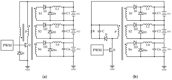
Figure 1.
(a) Schematic of the forward converter circuit with reset winding; (b) schematic of the RCDforward converter circuit.
The extra reset winding circuit is a lossless circuit. When the switch is on, the energy is transferred to the secondaries. The reset winding diode is reverse biased. When the switch is off, the negative voltage will be induced in the reset winding; thus, the core will be reset through the diode, which is forward biased.
The RCD circuit consists of a reset resistor, capacitor, and diode. When the switch is turned on, the higher cell will be discharged because of the increase in the current, but the lower cells start to charge. The voltage of the reset capacitor and resistor decreases, because the capacitor voltage will be discharged through the resistor; therefore, the efficiency of this circuit is low.
Similarly, two-switch forward converter types require one more switch and two extra diodes, resulting in more components. In Figure 2, the schematic of a two-switch forward is shown. When the switches Q1 and Q2 are turned on, the energy will be induced to the primary, and this energy will be transferred to the secondaries. In the next mode, when the switches are turned off, the voltage polarity of the primary and secondary will be reversed; therefore, the diodes D1 and D2 will be forward biased and will reset the transformer core. Therefore, the magnetizing energy is recovered.
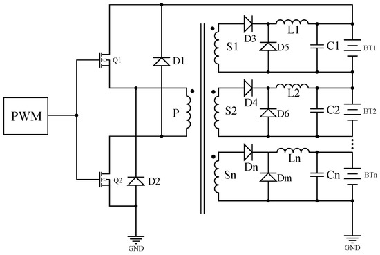
Figure 2.
Schematic of a two-switch forward converter circuit.
In order to investigate the difference between a conventional forward converter and the proposed forward converter with ZVS, the simulation results of the two-switch forward converter are presented.
The switching frequency was 50 kHz. The battery cells were modeled with the capacitors in series with the value of 0.5 F. The cell voltages were chosen from 3.1 V–3.6 V to present voltage differences. The switch was a MOSFET with a body diode, and it was controlled with PWM generated by a pulse generator. The transformer was a multi-winding transformer with one primary and eight secondaries. In Figure 3a, the cell voltages after balancing are presented. The transformer primary and secondary voltages are presented in Figure 3b. The primary current is shown in Figure 3c. The MOSFET and diode voltages are shown in Figure 3d.
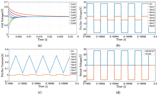
Figure 3.
(a) Cell voltages vs. time of the circuit; (b) primary/secondary voltages vs. time; (c) primary current vs. time of the circuit in the steady state; (d) MOSFET and diode voltages vs. time in the steady state.
3. The Proposed Forward Converter Circuit
In this section, the proposed forward balancing topology for lithium-based batteries will be given. The schematic of the forward circuit is presented in Figure 4. It consisted of eight cell in a series for a battery pack. The forward converter balancing method poses a fast balancing time, a simpler structure, and higher efficiency. The conventional forward balancing methods require an extra reset winding or RCD circuit in order to demagnetize the primary winding. The objective of the reset winding is to avoid the core of the transformer being saturated. Thus, more primary winding results in more circuitry and bulky size.
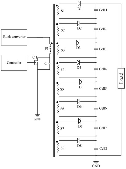
Figure 4.
Schematic of the proposed forward converter balancing circuit for eight lithium-based battery cells.
In the proposed circuit, a capacitor was implemented in parallel with the switch in order to demagnetize the transformer. The nominal voltage of each cell was 3.3 V, and the whole battery pack consisted of eight cells. Therefore, the whole battery voltage was 26.4 V. The voltage drop across each Schottky diode was considered as 0.3 V.
The operational principle can be divided into two stages.
In Stage 1, when the switch is turned on, the voltage will be transferred to the secondaries through the diodes. The primary and secondary voltage can be expressed as:
where N is the turn ratio , which can be calculated as:
For the forward converter, energy is transferred from the source to the load while the switch is closed. Therefore, magnetizing inductance was not a parameter included in the input-output relationship, and it was considered to be large.
In Stage 2, when the switch is turned off, the diode will be reverse biased; therefore, the energy cannot be transferred to the secondaries. The primary and secondary voltage can be written as:
The voltage through the magnetizing inductance is ; therefore, the average current through can be written as:
It can be noted in Equation (5) that the current is increasing linearly in when the switch is closed. The switch current can be expressed as:
The transformer was a ferrite ring core (dimensions of R25 × 14.8 × 10) with one primary and eight secondaries. In order to avoid non-uniform voltages of the secondaries, the proposed transformer topology used hairpin winding, which was made with zero-Ohm resistors as secondaries to allow an automated inspection and to keep distance in order to avoid short-circuit.
Each two hairpins (resistors in series) formed one secondary, which were connected in series on a PCB. In total, 16 resistors were used in order to implement eight secondaries, as shown in Figure 5. A magnetizing inductance of the transformer with the value of 1 mH was measured with an LCRmeter.
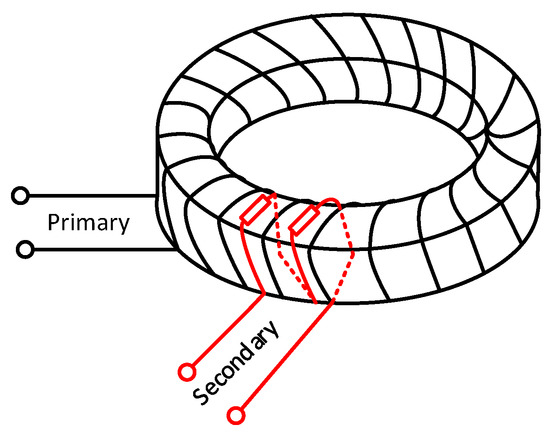
Figure 5.
Schematic of the core with the primary and one secondary.
The desired voltage at the output was 3.6 V, which is a 3.3-V nominal voltage of the battery plus 0.3 V the the diode voltage drop (Schottky diode), and the primary voltage was 40 V delivered from the buck converter. The secondary winding had two turns; therefore, the primary turn can be calculated as:
4. The Buck Converter
In order to equalize the battery packs, a buck converter was added to the circuit to balance the whole system. Each battery pack will be equalized by a separate forward converter and then the whole pack using a buck converter. The schematic of the buck converter and forward converters is presented in Figure 6. The duty cycle of the buck converter can be expressed as:
The inductor voltage can be calculated as:
by choosing , at 1% of the output current, which is 1 A. The inductance value can be calculated as:
The output capacitor for the buck with 1% of the full voltage ripple can be estimated as:
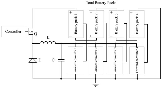
Figure 6.
Schematic of the buck converter and forward converters.
The buck converter switch was an N-channel MOSFET controlled by PWM with a frequency of 45 kHz and a duty cycle of 37.87%. The inductor was made by EE Ferrite Core Transformers with an air gap with a value of 4.96 mH. The input voltage was the voltage of the whole battery pack, which was 105.6 V, and the output voltage of 40 V.
5. Simulation Results
In this section, the simulation results are give to verify the viability of the proposed topology. The battery cells were modeled with the capacitors in series with the value of 0.5 F with different initial voltages, in order to model the cells. The cell voltages were chosen form 3.1 V–3.6 V to present significant voltage differences. The switch was a MOSFET with a body diode, and it was controlled with PWM generated by a pulse generator.
The switching frequency was chosen to be 50 kHz, with a 50% duty cycle. The diodes were considered to be ideal diodes. The transformer was a multi-winding transformer with one primary and eight secondaries.
The forward converter balancing had a fast balancing time and a simpler structure; however, the main disadvantage was that, the core of the transformer can be saturated without an accessory circuit.
A supplement circuit can be implemented by either an extra reset winding or RCD clamp circuit. The idea of additional demagnetizing winding results in a bulky size and a more complex implementation. Correspondingly, the RCD circuit has low efficiency, due to the fact that the magnetic energy will be dissipated through a resistor. Thus, the proposed forward converter employed neither an extra reset winding, nor an RCD snubber circuit.
The proposed topology applied the Zero Voltage Switching (ZVS) topology, which required a capacitor in parallel with the switch in order to demagnetize the transformer.
The gate to source voltage of the MOSFETs for the forward and buck converter is presented in Figure 7a,b, respectively. The forward had a duty cycle of 50%, and the transformer primary voltage was 40 V, while secondary was 3.6 V.

Figure 7.
(a) Gate to source voltage of the forward converter; (b) gate to source voltage of the buck converter.
The buck had a duty cycle of 36.63% in order to deliver 40 V for the forward converters. The buck should feed four forward converters, which were connected to the battery cells. Each pack consisted of eight cells. The number of packs can be extended for the desired application.
In Figure 8a, the cell voltages of the circuit with imbalances are presented. As can be seen, the voltage imbalances were chosen from 3.1 V–3.6 V, in order to verify the balancing time. The figure shows that all cells were equalized around 0.025 s (with 0.5 F). The primary and secondary voltages of the transformer in the steady state are shown in Figure 8b. The figure presents that the ZVS was achieved.
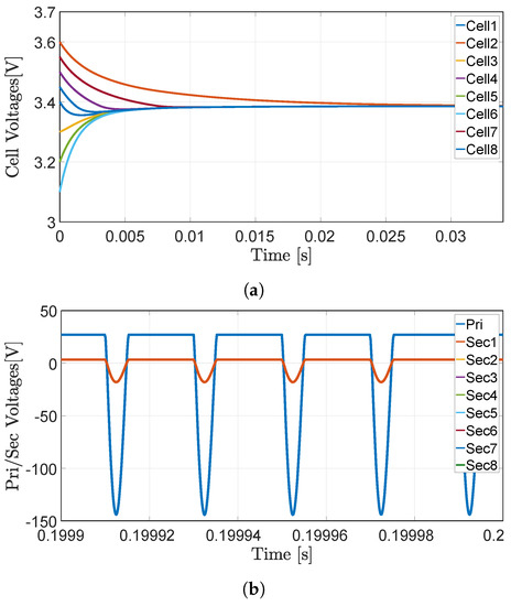
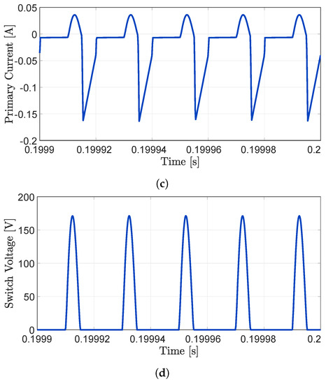
Figure 8.
(a) Cell voltages vs. time of the circuit; (b) primary and secondary voltages vs. time; (c) primary current vs. time of the circuit in the steady state; (d) switch voltage vs. time of the circuit in cells in the steady state.
The primary current waveform in the steady state is presented in Figure 8c. The switch voltage in the steady state is shown in Figure 8d. The drain to source voltage rating of the MOSFET should be at least two-times higher than the primary voltage.
To equalize the whole battery pack, a buck converter was designed. The buck converter will receive its input voltage from the battery pack, which was 105.6 V when all packs were fully charged. The output of the buck feed each forward converter to equalize every pack at the same time. In Figure 9, the battery pack (1–4) output voltages after balancing are shown. Each pack had different voltage imbalances.
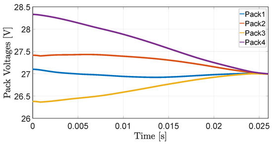
Figure 9.
Battery packs’ (1–4) equalized voltages (with 0.5 F/cell).
6. Experimental Results
In this section, the experimental results of the proposed forward-buck converter are presented. The forward converter was implemented with a ferrite ring core transformer with 22 primary winding turns and two turns for the secondaries. The secondary windings were made in such way that they had the same output voltages. To avoid non-uniform output voltage, the secondary windings were made with two hairpins made by two zero-Ohm resistors in series for each winding.
The resistors were soldered on the PCB and were connected at the bottom layer of the PCB, which would result in less leakage inductance and easy insertion in manufacturing. A magnetizing inductance of 1.06 mH was obtained. The secondary output voltages are presented in Table 1. As can be seen in the table, the output voltages were almost the same.

Table 1.
Secondary voltages at no-load.
The switch for the forward converter was a Surface-Mount Device (SMD) N-channel MOSFET with body diode. An N-channel MOSFET was chosen, in order to have less , and it was controlled by a microcontroller with a frequency of 45 kHz and a duty cycle of 45%. A capacitor was implemented in parallel with the switch to reset the transformer by the ZVS technique. With the ZVS technique, an extra reset winding would be unnecessary, resulting in less circuitry and being easy to implement. The capacitor value can be calculated as:
With the switching frequency of 46 kHz and magnetizing inductance value of 1.01 mH, the 11 nF capacitor was calculated. However, according to the parasitic capacitance of the transistor, the value of 2 nF was chosen to give the best result.
When the switch is turned on, the primary will receive the energy from buck converter, and it will be delivered to the secondaries through the SMD diodes. Unlike the conventional forward converter, which uses an extra diode and inductor as an output, this method requires only one diode and capacitor as an output, resulting in less components, which makes it more efficient. The N-channel MOSFET characteristics are shown in Table 2.

Table 2.
MOSFET characteristics.
All diodes were surface-mounted on a Schottky barrier rectifier in order to have less voltage drop across it, and this would waste less power, resulting in more efficiency. The diodes can be cooled via the PCB surface by increasing the copper area for each diode. The diode characteristics are shown in Table 3.

Table 3.
Schottky diode characteristics.
The output capacitors were an SMD multi-layer ceramic capacitor with the value of 100 F, a voltage rating of 6.3 V DC, and an operating temperature range of −55–85 °C. As was discussed before, the forward converters were fed by the buck converter. This operated based on the current control topology. In order to control the buck converter, an LED driver constant current control IC(HV9861A) was chosen. The controller was a fast average current controller, which was programmable with constant off-time switching.
The IC was equipped with a current limit comparator for hiccup-mode output short circuit, and also, internal over-temperature protection was provided. The internally-regulated voltage () was 7.5 V. The IC can be powered from a 15 V–450 V supply. The output current can be programmed by an internal 270-mV reference and a shunt.
The IC employed a patented control scheme, achieving fast and very accurate control of average current in the buck inductor through sensing the switching current only. Therefore, no compensation of the current-control loop was required. The timing resistor connected to the RTpin determined the off-time of the gate driver. The equation governing the off-time according to the datasheet can be expressed as:
The desired off-time was 20 s, according to a maximum switching frequency of 50 kHz. Thus, a value of 492.5 k for RT was obtained. Therefore, finally, the nearest value of 500 k was chosen for the resistor. The inductor value can be calculated as:
The desired output current was 1.5 A DC, 3 A (peak). Therefore, the inductance value can be obtained as 270 H. In order to calculate the capacitor value, first the charge Q need to be estimated. The total time was 20 s, and the value of Q can be expressed as:
Therefore, with the charge value of Q = 15 C, the capacitor value C = 37.5 F can be calculated according to Equation (18).
The duty-ratio range of the current control feedback was limited to D ≤ 0.8. A reduction in the current may occur when the voltage is greater than 80% of the input voltage. Therefore, there would be no problem, since the output voltage was 40 V. In the concept, it was taken into account that, the vehicle could operate using two packs instead of four packs, when two packs are discharged. The input voltage of the IC can vary from 15–450 VDC.
When this voltage was applied to the VINpin, it maintained a constant 7.5-V level at VDD. This voltage can also be used to power the IC and external circuitry connected to VDD. The VDD pin must be bypassed by a low ESRcapacitor to provide a low impedance path for the high frequency current of the gate driver.
The gate output was used to drive an external MOSFET. The gate charge, QG, of the switch should be less than 25 nC for the switching frequencies of ≤100 kHz. In Figure 10, the simplified schematic of the proposed buck converter is presented. The input was fed by the whole battery pack, which can vary from 105.6 V with all cells at nominal voltage to lower than this value. The sensing resistor R can determine the output current.
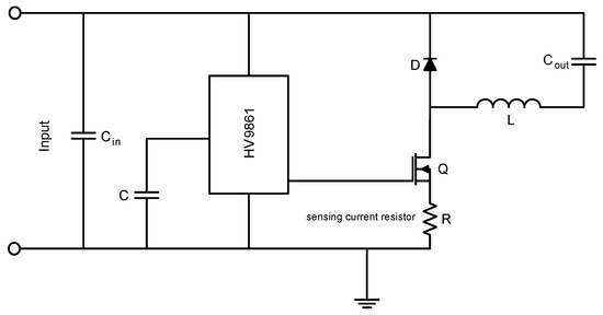
Figure 10.
Schematic of the buck converter.
The schematic of the buck-forward converter with one forward converter is shown in Figure 11. The output of the buck converter will feed four forward converter in parallel, but for simplicity one of them is presented in the figure. All forward converter will be fed by a fixed 40 V voltage which is originated from the whole battery pack voltage.
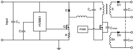
Figure 11.
Schematic of the buck-forward converter.
If some battery cells are below the nominal voltage, the input voltage of the buck will be decreased, but the system had a fixed regulated output voltage; therefore, the input voltage to the forward converters will be a fixed voltage of 40 V.
Figure 12 shows the gate to source and drain to source of the buck-forward circuit. As can be found in the figure, the zero switching voltage was achieved. The red waveform is the gate to source voltage, while the blue is drain to source voltage. In order to measure the drain to source voltage, the oscilloscope probe was applied.
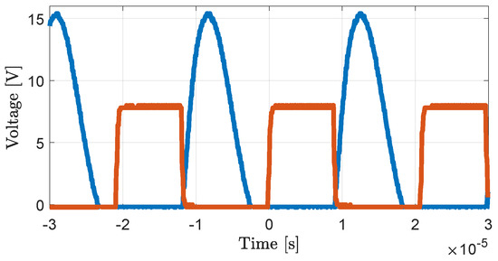
Figure 12.
Gate to source and drain to source voltages of the forward converter MOSFET Q1.
The primary and secondary voltage in the no-load condition is shown in Figure 13a,b, respectively. The oscilloscope probe and probe were applied to the primary and secondary side, respectively.

Figure 13.
(a) Primary voltage waveform of the forward converter circuit; (b) secondary voltage waveform of the forward converter.
In order to verify the buck-forward circuit, the proposed circuit was tested on lithium-ion batteries with a nominal voltage of 3.3 V and 1000-mAh capacity. The cell voltages were measured with the isolated circuit to the Arduino in order to extract the data. To test the system, some conditions were considered to obtain the experimental results.
Firstly, the cell charging process without balancing circuit was tested, and the result is shown in Figure 14a. It can be noticed that the cells started with different voltage values and showed the beginning of the charging process.
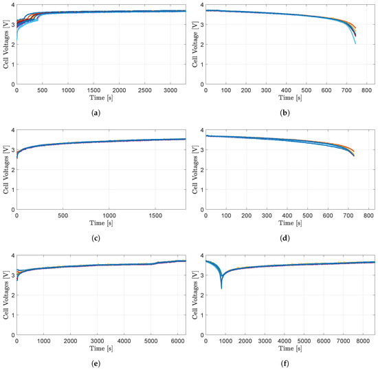
Figure 14.
(a) Cell charging voltages vs.time without the balancing circuit; (b) cell discharging voltages vs. time without the balancing circuit; (c) cell charging voltages vs. time with the proposed balancing circuit; (d) cell discharging voltages vs. time with the proposed balancing circuit; (e) cell charging voltages vs. time with the proposed balancing circuit with significant voltage differences; (f) cell discharging and charging voltages vs. time with the proposed balancing circuit.
In Figure 14b, the discharge process is presented. Firstly, all cells were fully charged and balanced to the nominal voltage. When the discharging was done, it can be seen that the cells were not discharged with the same voltage level, showing imbalanced cells with major voltage differences.
In order to test the balancing circuit, the cells with minor voltage differences were charged with the proposed buck-forward balancing circuit.
In Figure 14c, the charging with balancing circuit process is shown. It can be seen, during the charging/balancing process, that all cells were at the same voltage level, and they reached the nominal voltage at the end of the process with converging. Figure 14d shows the discharging process while the balancing circuit is present. It can be noticed that, at the end of the discharging, the cells were almost at the same value.
To verify the speed of the balancing circuit, the cells with major voltage differences were tested. The cell voltages were chosen from 2.74 V for the lower cell to 3.27 V for the higher one to have sufficient voltage differences. As can be seen in Figure 14e, all cells were fully charged and balanced at the same values with the balancing circuit.
Figure 14f shows the discharging and charging process at the same time. Firstly, all the cells were discharged with the balancing circuit, and then, they were charged again with the balancing circuit. As can found in the figure, during discharging and charging, all cells were converging at the beginning.
The efficiency of the buck-forward combination was calculated as an additional work, and the result is shown in Figure 15. In order to estimate the efficiency of the system, the circuit was tested with different loads. The output current varied from 0.11 A–0.92 A to achieve the result.
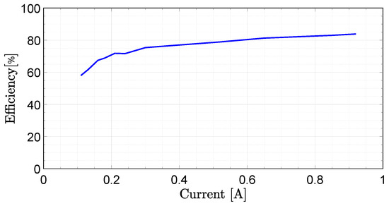
Figure 15.
The efficiency of the forward-buck combination.
It has been found that the higher efficiency of 83.84% can be obtained with a 0.92-A output current for the buck-forward converter circuit.
The practical implementation of the whole battery balancing system and PCB prototype of the forward converter are presented in Figure 16a,b, respectively. As can be seen in Figure 16a, the buck converter was fed from whole battery packs, which was 105.6 V if all cells were at the nominal voltage and lower than this value for the imbalanced cells.
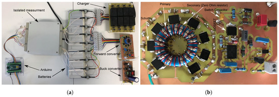
Figure 16.
(a) Practical implementation of the forward-buck converter; (b) PCB prototype of the forward converter.
The proposed buck converter can operate from 80 V–150 V input voltage and delivered 40-V regulated output. In the next stage, the forward converters that were connected to each battery pack will be fed by the buck converter.
7. Conclusions
In this paper, a special multiple output forward converter equalizing circuit is proposed. It is fed by a buck converter from lithium-based batteries in ultralight electrical vehicles. The special arrangement makes it possible to equalizing eight cells or more in series in a battery pack. It can be repeated for the other battery packs in the full battery. A common 40-V buck converter is feeding them, so it is a solution for a full battery equalization. Each battery pack consists of eight cells in series, and the whole battery bank consists of four battery packs in series. The proposed method combines a simple structure with a fast balancing time. This method applies a single-transistor ZVS technique, which also avoids a demagnetizing winding. It needs only one transistor, has lower switching losses, and does not require a demagnetizing winding. The proposed circuit equalizes each battery pack starting from a common voltage, made by a buck converter. Hence, all cells are equalized in the same way, without sophisticated or sensitive voltage measurements. The buck converter is used in current mode, with a limited voltage. The proposed forward type uses only one diode per cell and one transistor, making it cost effective. The secondaries of the proposed transformer use hairpin windings, using two zero-Ohm resistors in series as secondaries. This permits a large number of secondaries and guaranties uniform voltage by symmetry. Each of the two hairpins form one secondary, which are connected in series at the bottom of the PCB. The system can also be used to finalize charging of the batteries or equalizing the cells after a replacement of a cell or a battery set. The number of cells or battery packs can be extended to the desired numbers. Experimental and simulation results were performed to testify the feasibility of the system.
Author Contributions
Conceptualization, A.F.M. and A.V.d.B.; methodology, A.F.M.; software, A.F.M.; validation, A.F.M.; formal analysis, A.F.M.; investigation, A.F.M.; resources, A.F.M.; data curation, A.F.M.; writing, original draft preparation, A.F.M.; writing, review and editing, A.F.M.; visualization, A.F.M.; supervision, A.V.d.B.
Funding
This research received no external funding.
Conflicts of Interest
The authors declare no conflict of interest.
References
- Danilov, D.; Notten, P.H.L. Adaptive Battery Management Systems for the new generation of Electrical Vehicles. In Proceedings of the 2009 IEEE Vehicle Power and Propulsion Conference, Dearborn, MI, USA, 7–10 September 2009; pp. 317–320. [Google Scholar]
- Sen, C.; Kar, N.C. Battery pack modeling for the analysis of battery management system of a hybrid electric vehicle. In Proceedings of the 2009 IEEE Vehicle Power and Propulsion Conference, Dearborn, MI, USA, 7–10 September 2009; pp. 207–212. [Google Scholar]
- Miniguano, H.; Raga, C.; Barrado, A.; Lázaro, A.; Zumel, P.; Olías, E. A comparative study and parameterization of electrical battery models applied to hybrid electric vehicles. In Proceedings of the 2016 International Conference on Electrical Systems for Aircraft, Railway, Ship Propulsion and Road Vehicles & International Transportation Electrification Conference (ESARS-ITEC), Toulouse, France, 2–4 November 2016; pp. 1–6. [Google Scholar]
- Saxena, N.; Hussain, I.; Singh, B.; Vyas, A.L. Implementation of a Grid-Integrated PV-Battery System for Residential and Electrical Vehicle Applications. IEEE Trans. Ind. Electron. 2018, 65, 6592–6601. [Google Scholar] [CrossRef]
- Bonfiglio, C.; Roessler, W. A cost optimized battery management system with active cell balancing for lithium ion battery stacks. In Proceedings of the 2009 IEEE Vehicle Power and Propulsion Conference, Dearborn, MI, USA, 7–10 September 2009; pp. 304–309. [Google Scholar]
- Xu, J.; Cao, B.; Cao, J.; Zou, Z.; Mi, C.C.; Chen, Z. A Comparison Study of the Model Based SOC Estimation Methods for Lithium-Ion Batteries. In Proceedings of the 2013 IEEE Vehicle Power and Propulsion Conference (VPPC), Beijing, China, 15–18 October 2009; pp. 1–5. [Google Scholar]
- Lu, L.; Han, X.; Li, J.; Hua, J.; Ouyang, M. A review on the key issues for lithium-ion battery management in electric vehicles. J. Power Sources 2013, 226, 272–288. [Google Scholar] [CrossRef]
- Mi, C.; Masrur, M.A. Hybrid Electric Vehicles: Principles and Applications with Practical Perspectives; John Wiley & Sons: Hoboken, NJ, USA, 2017. [Google Scholar]
- Moghaddam, A.F.; Van den Bossche, A. Electric Vehicles Charging Concepts for Lithium Based Batteries. In Proceedings of the 2018 7th International Conference on Renewable Energy Research and Applications (ICRERA), Paris, France, 14–17 October 2018; pp. 397–401. [Google Scholar]
- Moghaddam, A.F.; Van den Bossche, A. An Active Cell Equalization Technique for Lithium Ion Batteries Based on Inductor Balancing. In Proceedings of the 2018 9th International Conference on Mechanical and Aerospace Engineering (ICMAE), Budapest, Hungary, 10–13 July 2018; pp. 274–278. [Google Scholar]
- Moghaddam, A.F.; Van den Bossche, A. A Cell Equalization Method Based on Resonant Switched Capacitor Balancing for Lithium Ion Batteries. In Proceedings of the 2018 9th International Conference on Mechanical and Aerospace Engineering (ICMAE), Budapest, Hungary, 10–13 July 2018; pp. 337–341. [Google Scholar]
- Lievre, A.; Sari, A.; Venet, P.; Hijazi, A.; Ouattara-Brigaudet, M.; Pelissier, S. Practical Online Estimation of Lithium-Ion Battery Apparent Series Resistance for Mild Hybrid Vehicles. IEEE Trans. Veh. Technol. 2016, 65, 4505–4511. [Google Scholar] [CrossRef]
- Shang, Y.; Xia, B.; Zhang, C.; Cui, N.; Yang, J.; Mi, C. An automatic battery equalizer based on forward and flyback conversion for series-connected battery strings. In Proceedings of the 2017 IEEE Applied Power Electronics Conference and Exposition (APEC), Tampa, FL, USA, 26–30 March 2017; pp. 3218–3222. [Google Scholar]
- Uno, M.; Tanaka, K. Single-Switch Cell Voltage Equalizer Using Multistacked Buck-Boost Converters Operating in Discontinuous Conduction Mode for Series-Connected Energy Storage Cells. IEEE Trans. Veh. Technol. 2011, 60, 3635–3645. [Google Scholar] [CrossRef]
- Emadi, A.; Lee, Y.J.; Rajashekara, K. Power Electronics and Motor Drives in Electric, Hybrid Electric, and Plug-In Hybrid Electric Vehicles. IEEE Trans. Ind. Electron. 2008, 55, 2237–2245. [Google Scholar] [CrossRef]
- Hussein, A.A. Capacity fade estimation in electric vehicles Li-ion batteries using artificial neural networks. In Proceedings of the 2013 IEEE Energy Conversion Congress and Exposition, Denver, CO, USA, 15–19 September 2013; pp. 677–681. [Google Scholar]
- Liu, X.; Zeng, G.; He, Y.; Dong, B.; Xu, X. Research on the capacity fading characteristics of a Li-ion battery based on an equivalent thermal model. In Proceedings of the 2015 International Conference on Intelligent Computing and Internet of Things, Harbin, China, 17–18 January 2015; pp. 145–150. [Google Scholar]
- Uno, M.; Tanaka, K. Accelerated Charge–Discharge Cycling Test and Cycle Life Prediction Model for Supercapacitors in Alternative Battery Applications. IEEE Trans. Ind. Electron. 2012, 59, 4704–4712. [Google Scholar] [CrossRef]
- Lin, X.; Stefanopoulou, A.G.; Li, Y.; Anderson, R.D. State of Charge Imbalance Estimation for Battery Strings Under Reduced Voltage Sensing. IEEE Trans. Control Syst. Technol. 2015, 23, 1052–1062. [Google Scholar]
- Kim, Y.; Samad, N.A.; Oh, K.; Siegel, J.B.; Epureanu, B.I.; Stefanopoulou, A.G. Estimating state-of-charge imbalance of batteries using force measurements. In Proceedings of the 2016 American Control Conference (ACC), Boston, MA, USA, 6–8 July 2016; pp. 1500–1505. [Google Scholar]
- Kim, C.; Kim, M.; Kim, Y.; Moon, G. A modularized charge equalizer using battery monitoring IC for series connected Li-Ion battery strings in an electric vehicle. IEEE Trans. Power Electron. 2013, 28, 3779–3787. [Google Scholar] [CrossRef]
- Park, H.; Kim, C.; Park, K.; Moon, G.; Lee, J. Design of a Charge Equalizer Based on Battery Modularization. IEEE Trans. Veh. Technol. 2009, 58, 3216–3223. [Google Scholar] [CrossRef]
- Baughman, A.C.; Ferdowsi, M. Double-Tiered Switched-Capacitor Battery Charge Equalization Technique. IEEE Trans. Ind. Electron. 2008, 55, 2277–2285. [Google Scholar] [CrossRef]
- Kutkut, N.H.; Divan, D.M. Dynamic equalization techniques for series battery stacks. In Proceedings of the Intelec’96—International Telecommunications Energy Conference, Boston, MA, USA, 6–10 October 1996; pp. 514–521. [Google Scholar]
- Zhang, X.; Liu, P.; Wang, D. The design and implementation of smart battery management system balance technology. J. Converg. Inf. Technol. 2011, 6, 108–116. [Google Scholar]
- Kobzev, G.A. Switched-capacitor systems for battery equalization. In Proceedings of the 6th International Scientific and Practical Conference of Students, Post-graduates and Young Scientists. Modern Techniques and Technology (MTT’2000), Tomsk, Russia, 3 March 2000; pp. 57–59. [Google Scholar]
- Zhi-Guo, K.; Chun-Bo, Z.; Ren-Gui, L.; Shu-Kang, C. Comparison and evaluation of charge equalization technique for series connected batteries. In Proceedings of the 2006 37th IEEE Power Electronics Specialists Conference, Jeju, Korea, 18–22 June 2006; pp. 1–6. [Google Scholar]
- Stuart, T.A.; Zhu, W. Fast equalization for large lithium ion batteries. IEEE Aerosp. Electron. Syst. Mag. 2009, 24, 27–31. [Google Scholar] [CrossRef]
- Lindemark, B. Individual cell voltage equalizers (ICE) for reliable battery performance. In Proceedings of the Thirteenth International Telecommunications Energy Conference, INTELEC 91, Kyoto, Japan, 5–8 November 1991; pp. 196–201. [Google Scholar]
- Baughman, A.C.; Ferdowsi, M. Double-tiered capacitive shuttling method for balancing series-connected batteries. In Proceedings of the 2005 IEEE Vehicle Power and Propulsion Conference, Chicago, IL, USA, 7 September 2005; pp. 109–113. [Google Scholar]
- Moghaddam, A.F.; Van den Bossche, A. Multi-Winding Equalization Technique for Lithium Ion Batteries for Electrical Vehicles. In Proceedings of the 2018 7th International Conference on Renewable Energy Research and Applications (ICRERA), Paris, France, 14–17 October 2018; pp. 139–143. [Google Scholar]
- Li, S.; Mi, C.C.; Zhang, M. A High-Efficiency Active Battery-Balancing Circuit Using Multiwinding Transformer. IEEE Trans. Ind. Appl. 2013, 49, 198–207. [Google Scholar] [CrossRef]
- Lim, C.-S.; Kim, R.-Y.; Hyun, D.-S. Battery voltage sensorless charge equalizer using the multi-winding transformer. In Proceedings of the 2012 IEEE Vehicle Power and Propulsion Conference, Seoul, Korea, 9–12 October 2012; pp. 789–793. [Google Scholar]
- Moghaddam, A.F.; Van den Bossche, A. An Efficient Equalizing Method for Lithium-Ion Batteries Based on Coupled Inductor Balancing. Electronics 2019, 8, 136. [Google Scholar] [CrossRef]
- Moo, C.S.; Hsieh, Y.C.; Tsai, I.S.; Cheng, J.C. Dynamic charge equalisation for series-connected batteries. IEE Proc. Electr. Power Appl. 2003, 150, 501–505. [Google Scholar] [CrossRef]
- Sun, J.; Lu, R.; Wei, G.; Xu, B.; Zhu, C. A high efficiency equalizer based on forward converter for series connected battery string. In Proceedings of the 2012 IEEE Vehicle Power and Propulsion Conference, Seoul, Korea, 9–12 October 2012; pp. 376–379. [Google Scholar]
- Lee, Y.; Yun, J.; Bae, S. Active cell balancing circuit based on the forward converter with an RCD circuit. In Proceedings of the 2015 9th International Conference on Power Electronics and ECCE Asia (ICPE-ECCE Asia), Seoul, Korea, 1–5 June 2015; pp. 2887–2892. [Google Scholar]
- Gerislioglu, B.; Ozturk, F.; Sanli, A.E.; Gunlu, G. The multi-windings forward structure battery balancing. In Proceedings of the 2014 11th International Conference on Electronics, Computer and Computation (ICECCO), Abuja, Nigeria, 29 September–1 October 2014; pp. 1–4. [Google Scholar]
- Tan, F.D. The forward converter: from the classic to the contemporary. In Proceedings of the Seventeenth Annual IEEE Applied Power Electronics Conference and Exposition, Dallas, TX, USA, 10–14 March 2002; pp. 857–863. [Google Scholar]
- Bridge, C.D. Clamp voltage analysis for RCD forward converters. In Proceedings of the Fifteenth Annual IEEE Applied Power Electronics Conference and Exposition, New Orleans, LA, USA, 6–10 February 2000; pp. 959–965. [Google Scholar]
- Qin, X.; Hu, H.; Wu, H.; Xing, Y.; Ma, X. A series-input forward converter with shared RCD cell for high-reliability and wide input voltage range applications. In Proceedings of the 2013 IEEE Energy Conversion Congress and Exposition, Denver, CO, USA, 15–19 September 2013; pp. 154–158. [Google Scholar]
© 2019 by the authors. Licensee MDPI, Basel, Switzerland. This article is an open access article distributed under the terms and conditions of the Creative Commons Attribution (CC BY) license (http://creativecommons.org/licenses/by/4.0/).