Article

Power Supply Switch Circuit for Intermittent Energy Harvesting

1
Department of Mechanical Engineering, Virginia Polytechnic Institute and State University, Blacksburg, VA 24061, USA
2
Department of Mechanical Engineering, University of Maryland Baltimore County, Baltimore, MD 21250, USA
*
Author to whom correspondence should be addressed.
Electronics 2019, 8(12), 1446; https://doi.org/10.3390/electronics8121446
Submission received: 31 October 2019 / Revised: 21 November 2019 / Accepted: 23 November 2019 / Published: 1 December 2019
(This article belongs to the Special Issue Energy Harvesting and Storage Applications)

Abstract

:
Energy harvesters generate power only when ambient energy is available, and power loss is significant when the harvester does not produce energy and its power management circuit is still turned on. This paper proposes a new high-efficiency power management circuit for intermittent vibration energy harvesting. The proposed circuit is unique in terms of autonomous power supply switch between harvester and storage device (battery), as well as self-start and control of the operation mode (between active and sleep modes). The self-start controller saves power during an inactive period and the impedance matching concept enables maximum power transfer to the storage device. The proposed circuit is prototyped and tested with an intermittent vibration energy harvester. Test results found that the daily energy consumption of the proposed circuit is smaller than that of the resistive matching circuit: 0.75 J less in sleep mode and 0.04 J less in active mode with self-start.

1. Introduction

The operation and maintenance (O&M) cost is very high for wind energy and it makes wind energy difficult to be economically competitive energy sources [1,2,3]. To reduce O&M costs of a wind turbine, predictive maintenance is necessary via smart remote monitoring that enables wind operators to plan maintenance (e.g., repairs or replacement) only when needed and avoid unnecessary and costly up-tower jobs [4,5,6,7,8,9]. The predictive maintenance system for a nacelle (central unit) has been well established, but the one for a turbine blade is very challenging because of the lack of proper power supply. Wired power is difficult to use because the long cables (up to 80 m) require additional maintenance and possibly attract lightning. The use of the battery is an alternative choice, but its limited energy and lifetime make it an inappropriate solution [10].
A self-powered wireless monitoring system is a promising solution for sustainable wind turbine blade monitoring. Photovoltaic and vibrational energy harvesting is a possible solution that converts sunlight and kinematic/rotational energy into electrical energy, respectively. However, a photovoltaic energy harvesting system cannot be mounted on the blade due to its adverse effect on blade aerodynamics [11]. An electromagnetic energy harvesting system can be mounted within the blade and does not affect blade aerodynamics, but it should be designed as compact, not to affect the blade motion due to its heavy weight [12,13]. A piezoelectric energy harvester (PEH) is lightweight compared to the electromagnetic option. However, the design of an efficient vibrational energy harvesting system (electromagnetic, piezoelectric) is still challenging because it does not effectively capture random vibrations in a wind turbine blade [14,15].
To transfer the output power efficiently from PEH to a wireless sensor node (WSN), power management circuits have been actively researched [16,17,18,19,20,21]. Synchronized Switch Harvesting on Inductor (SSHI) is one of the popular options for PEH. SSHI can reduce the internal capacitance of PEH’s effects so that PEH can continuously supply the power to the load. In [22], SSHI showed 85% of AC-DC conversion efficiency. However, SSHI can increase the efficiency of AC-DC conversion only when both electromechanical coupling factor k2 and mechanical quality factor Qm are low [23]. Considering intermittent and random ambient vibration, maximum power point tracking (MPPT) was actively researched. When the vibration frequency of PEH is changed, the impedance of PEH is also changed. MPPT can adaptively match the impedance with the PEH’s to maintain the maximum power transfer condition. Among the previous studies, Shim et al. [24] showed the highest MPPT efficiency (99%).
Still, the research on the power management circuit considering intermittent and random input energy is in infancy. Gyorgy et al. [25] proposed a self-start circuit, but it has some drawbacks such as 340 s of cold-starting time for activating a power management circuit, and no sleep mode control. In [26,27,28], junction gate field-effect transistor (JFET) based start-up circuits were proposed for low voltage start-up, which can boost the several mV to the start-up voltage level (>1.5 V) for starting operation of power management circuit. However, this topology is only beneficial to energy harvesters that generate low voltage such as electromagnet and thermoelectric energy harvester. Our previous studies designed start-up circuits that are suitable to PEH with the intermittent and random input conditions [29,30,31] in which the controllers autonomously switch between sleep and active modes considering random and intermittent energy. In [29], the impedance matching circuit with sleep mode reduced the power loss using a controller powered by a storage device (e.g., battery) when there is no harvested energy. But the storage device needs to be precharged to start the circuit. If the storage device is fully drained initially, the impedance matching circuit cannot operate. In [30,31], self-start impedance matching circuits were designed to operate the circuit even if the storage device is fully drained. However, the significant voltage drop from the PEH (several tens volts) to the oscillator (its minimum operation voltage) causes a larger power consumption of the controller. In [32], a self-powered impedance matching with MPPT is proposed to self-start the circuit when a battery is fully drained, and power the circuit by the battery when it has enough energy. The microcontroller unit (MCU) in [33], however, consumes over 400 µW and it is not a practical solution for small power harvesting.
The objective of this study is the minimization of power consumption of the controller considering the intermittence and randomness of ambient source in the wind turbine blade. The proposed PEH vibrates its natural frequency regardless of operating conditions of wind turbines and it does not need to track the maximum power point. Also, the proposed self-start controller is designed for ultra-low power consumption by self-start and switching the power supply to the oscillator between the PEH and the storage device. The rest of the paper is organized as follows: Section 2 presents a conceptual design of the PEH with gravity-induced rotator as well as its analysis and experimental verification. Section 3 proposes the power management circuit with the self-start controller. Section 4 presents the experimental results to demonstrate the efficiency of the circuit. Section 5 concludes the paper.

2. PEH with Gravity-Induced Disk

The harvester studied in this paper can be installed on a large scale rotating object (e.g., inside wind turbine blade) to convert its kinetic energy to vibration and electrical energy. In a normal operation of a wind turbine (as shown in Figure 1), for example, the disk orientation is toward the ground due to gravity while the cantilevered harvester (PEH) follows the blade orientation. This setup generates relative motion between the disk and the PEH, and vibration of the cantilevered PEH due to the magnetic force between the disk and the beam.
The harvester studied in this research consists of a cantilevered PZT beam (PPA-2011, MIDE corporation, MA, USA) with a tip magnet (BC84, K&J Magnetics, Inc.), and a rotating disk with another magnet as illustrated in Figure 1 and Figure 2 [15,33]. The material properties of the piezoelectric cantilever are presented in Table 1. The disk diameter used in this paper is approximately 15 cm, but is exaggerated in Figure 1 for a better understanding of the mechanism. The test setup in Figure 2 is composed of a wooden plate (replicating a small wind turbine blade, about 1.2 meter long), a DC motor for blade rotation, a slip ring for acquiring the electrical signals from the PEH on the blade, and rpm sensor for measuring the blade rotation speed. The blade speed is set to 10 rpm, which is a typical rotation speed of the wind turbine blade.

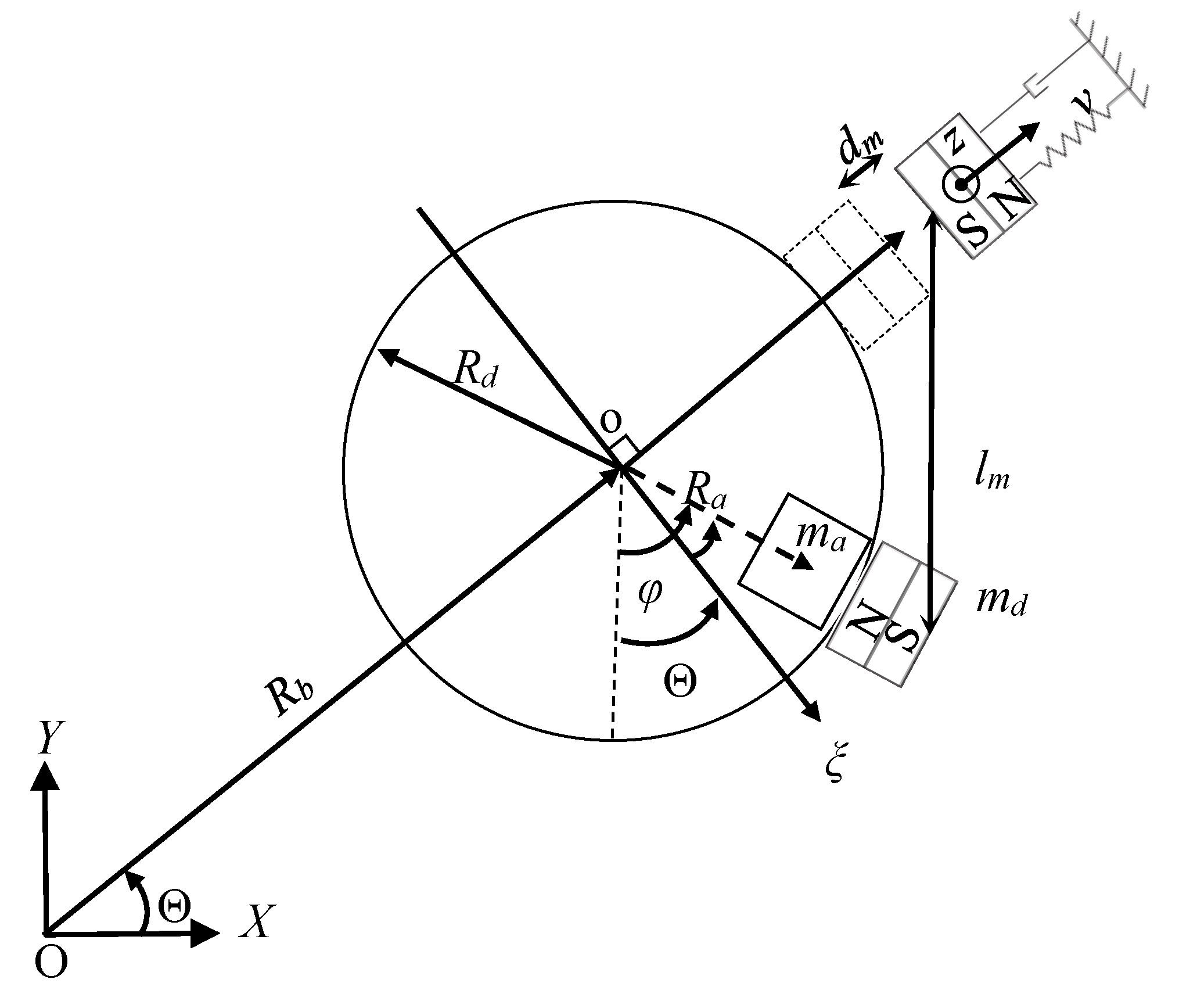
2.1. Dynamics Modeling of Harvester and Simulation

The schematic model of the PEH part is illustrated in Figure 3. Three coordinate systems are defined in this figure: A global coordinate system (X,Y) at the blade center, and two local coordinate systems fixed on the blade: (1) (ξ,η) at the disk center, and (2) (z,v) at the fixed end of the PEH beam.
The system equations of motion are derived using Lagrange’s equation, with the parameter defined in Table 2, as [15]:
θ ¨ c 1 Θ ˙ R b I Θ ˙ 2 cos θ + g I sin ( θ + Θ ) + R m s ( R m s b + ϕ ( l ) q ( t ) ) cos θ I c × l m 2 ( θ , q ( t ) ) × ( a e b × l m ( θ , v ( l ) ) + c e d × l m ( θ , v ( l ) ) ) = 0
q ¨ ( t ) + α q ( t ) + τ sin Θ c 2 q ˙ χ V ( t ) ϕ n ( l ) ( R m s b + ϕ n ( l ) q ( t ) ) R m s ϕ n ( l ) sin θ l m 2 ( θ , q ( t ) ) × ( a e b × l m ( θ , v ( l ) ) + c e d × l m ( θ , v ( l ) ) ) ( γ 1 + γ 2 q ( t ) ) Θ ˙ 2 = 0
V ˙ ( t ) κ V ( t ) ς q ˙ ( t ) = 0
where q(t) is the normal coordinate to describe the PEH vibration by variable separation concept v(z,t) = φ(t)q(t) where φ(t) is the first mode shape of the cantilever beam. θ is the local angular position of the disk, and Θ is the global blade orientation. Equations (1) and (2) describe the disk motion and the PEH vibration, respectively. They are coupled with the magnetic force term. Equation (3) describes the voltage output of the PEH, coupled with Equation (2) by the electromechanical coupling term χ. The constants I, Ida, Ic, α, χ, τ, κ, ϛ, γ1, and γ2 are defined as
I = m a R a 2 + m m R m 2 + I d a m a R a + m m R m
I d a = 1 2 m d R d 2 + m a 12 ( l a 2 + w a 2 ) + m m 12 ( l m 2 + w m 2 )
I c = m a R a 2 + m m R m 2 + I d a
α = 0 l E I ( 2 ϕ n ( z ) z 2 ) 2 d z
χ = 1 2 0 l υ p 2 ϕ n ( z ) z 2 d z
τ = m t g ϕ n ( l )
γ 1 = l m s p l s d + m t l t
γ 2 = m s p 0 l ϕ n ( z ) d z + m t ϕ n ( l )
κ = 1 R C p
ς = χ C p .
The three equations of motion, Equations (1) to (3), are solved using the ODE45 function in MATLAB software. The PEH vibration response v(z=lp,t) at blade speed 10 rpm is studied in Figure 4. The PEH experiences magnetic force by the passing the magnet on the disk and bends initially (about 0.9 mm around 1 s and 7 s, Figure 4), and vibrates at its natural frequency (34 Hz) right after the disk magnet passes the harvester beam (around 1–3 s and 7–9 s). This vibration behavior is repeated whenever the disk magnet passes the harvester beam. The fixed vibration frequency of the PEH results in a fixed electrical impedance, which dramatically simplifies the design of the charging circuit because it doesn’t need to track the optimum impedance load. This is one of the advantages of the proposed frequency up conversion technique. The beam deflection due to the gravitation is also observed between magnetic impact (less than 0.05 mm), but it does not seriously affect the harvester performance. More detailed dynamic model analysis and experimental verification are available in our previous study [15].

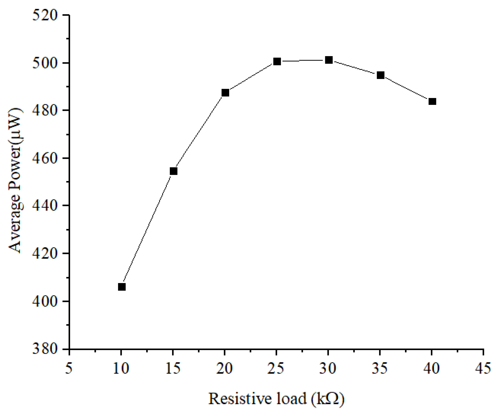
2.2. Prototype of A PEH With Gravity-Induced Rotator and Experimental Results

Before connecting the PEH to the power management circuit, the PZT cantilever is directly connected to an adjustable resistive load where the average power is measured. The time history of the voltage measured at the resistive load is shown in Figure 5. One voltage generation cycle is composed of two parts: The output voltage generation period for 1 s and the rest period for 5 s. These durations correspond to the PEH beam vibration right after magnetic impact for about 1 s and the rest for 5 s in Figure 4. The average power of PEH versus load resistance is shown in Figure 6 that finds the optimal PEH resistance at 30 kΩ and the average power as 0.501 mW. Understanding intermittent power generation mode of the PEH as well as power charging efficiency depending on impedance, there is a need for smart power management circuit to effectively charge the energy.

3. Proposed Power Management Circuit

The proposed circuit consists of a full-bridge rectifier, a buck-boost converter, a self-start controller, and an oscillator as shown in Figure 7. Especially the self-start controller is designed to minimize the power consumption of the circuit by (1) self-start, (2) control of the operation mode (active and sleep modes), and (3) switching the power supply to the oscillator between PEH and storage device. The oscillator is used for driving the buck-boost converter that matches impedance.

3.1. Rectifier and Buck-Boost DC–DC Converter

A full-bridge rectifier converts AC voltage generated by the piezoelectric cantilever to DC voltage. In general, the power loss of the rectifier is negligible in most PEH harvesting for two reasons. First, the peak voltage from the PEH is sufficiently large, up to several tens of volts, and the voltage drop across the rectifier (diodes) is not critical. Second, the diode current is small due to the large impedance of the PEH.
An impedance matching circuit is required when supplying power from PEH to a wireless sensor node (WSN) because the resistive impedance of the wireless sensor node is extremely lower than that of the PEH. The input impedance of buck converter and boost converter in critical conduction mode (CCM) and discontinues conduction mode (DCM) are affected by the output resistance and input voltage that are continuously changed in a real application. Thus, buck converter and boost converter with CCM and DCM mode cannot maintain an optimum impedance to match with PEH. In the proposed power management circuit (PMC), a buck-boost DC-DC converter is used to match the input resistance of buck-boost converter to the impedance of the PEH for maximum power transfer. The emulated input impedance Rin of a buck-boost converter operated in the DCM is expressed as [14]:
R i n = 2 · L T s · D 2
where L is the inductance, Ts is the switching period of the converter, and D is the duty cycle. The target impedance is usually obtained by adjusting the duty cycle D and/or the switching period Ts. A major advantage of the buck-booster converter operated in DCM is that the input impedance is independent of its operating conditions, such as input and output voltages and load resistance.

3.2. Self-Start Controller and Oscillator

The proposed self-start controller is designed to enable both self-start and switching the power supply to the oscillator between the PEH and the storage device. The oscillator is powered from the storage device when sufficient power is available in the storage device. When the storage device is fully drained, however, the self-start controller switches the power supply from the storage device to the PEH. Power consumption by the PEH is bigger because of the high voltage drop process, so powering the oscillator from the PEH is limited only when the storage device is fully drained. When the PEH stops power generation, the self-start controller switches the operation mode from active to sleep mode to minimize its power consumption.

3.2.1. Self-Start Controller

The self-start controller consists of a Schottky diode D5, a low drop out regulator (LDO) U5, capacitors C3, C4, an AND logic gate U3, an inverter logic gate U4, and a comparator with reference U2. D11 is used to prevent the energy stored in C5 from backing up to the DC-DC converter when Q1 is turned “on”. LDO U5 is used to step down the voltage from Vcc to the operation voltage of the oscillator. The ON/OFF pin in LDO is used for controlling the sleep and active mode of LDO, and C3 and C4 are used for the stabilization of LDO. The comparator with reference U2 controls to switch the power supply of the oscillator between the PEH and the storage device. The input of the AND logic gate U3 is connected with the rectified voltage from the PEH Vcc and the output voltage of comparator VU2, and they generate the logic signal to control active and sleep mode of the circuit as well as power the oscillator. The inverter logic gate U4 reverses signal VU2 to control ON and OFF of LDO. The operation of the self-start controller is described per two different operation cases depending on the storage device voltage as below:
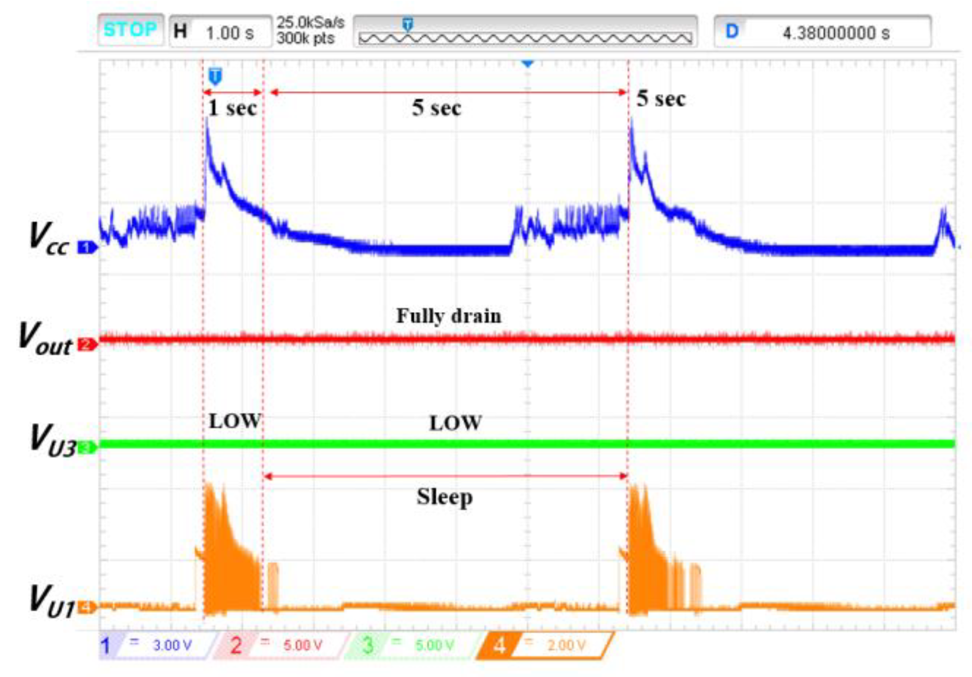
  • Case 1: When the storage device is fully drained and Vcc is higher than the threshold because of the energy generated by the PEH. In this case, Vout is lower than the threshold voltage, and both the comparator U2 and the AND gate U3 are deactivated because the storage device voltage is lower than the minimum operating voltage of U2 and U3. That makes the output of U2 and U3 LOW signal. The inverter logic gate U4 receives LOW and reverses it to HIGH that turns ON LDO U5 that starts powering the oscillator for impedance matching. When the PEH stops power generation, the inverter logic gate U4 and LDO U5 automatically stop the operation to save power.
  • Case 1 to Case 2: When Vout is higher than the threshold value (2 V), U2 is activated to compare Vref and the output of voltage divider sourced by Vout. When this output is higher than Vref, an operation case is changed from Case 1 to Case 2.
  • Case 2: When the storage device is charged to power the controller. In this case, Vout becomes higher than the threshold and the comparator U2 sends HIGH signal to one input of AND gate U3 and the inverter gate U4. The inverter gate U4 receives HIGH from U2 and sends LOW to the LDO (ON/OFF pin) to deactivate the LDO and save power. When the PEH generates power, Vcc is higher than the threshold, and all of the inputs to the AND gate U3 are HIGH as well as its output. Then it starts powering the oscillator. When the PEH stops power generation and Vcc becomes lower than the threshold voltage, the output of AND gate U3 becomes LOW and it stops power supply to the oscillator. In this case, LDO turns naturally off because the current does not flow to LDO.
The proposed self-start circuit enables self-start in Case 1, and it saves several hundreds of microwatts because it can eliminate the step-down process of LDO in Case 2. In addition, the proposed self-start circuit switches the operation mode of the controller from active to sleep with ultra-low power consumption.

3.2.2. Oscillator

The oscillator is designed to generate the square wave to control the buck-boost DC–DC switching converter based on Kong’s work [16]. The duty cycle D and the switching period Ts of the square wave are given as Equations (15) and (16) for controlling the DC-DC converter.
T S = 1 F S =   ( R 6 + R 7 ) C 5 l n 2 1
D 1 = R 6 R 7
The capacitor (C5) is charged from the output voltage of U1. Once the capacitor voltage reaches two-thirds of the supply voltage, the output voltage comparator goes zero, and C5 is discharged through R7. If the capacitor voltage reaches one-third of the supply voltage, the output voltage of the comparator becomes high. The entire cycle is repeated for generating the square wave. The switching frequency of the buck-boost converter is around 3 kHz.

4. Prototype and Experimental Results

The proposed circuit is implemented using the electrical components listed in Table 3 that are selected to minimize the power dissipation. A supercapacitor is used for the energy storage device. The circuit is prototyped in a printed circuit board (PCB) and integrated with the proposed PEH as shown in Figure 1.

4.1. Self-Start Controller and Oscillator

4.1.1. Case 1

Case 1 tests when the storage device is fully drained. The voltage waveforms from the LDO input (Vcc, blue), the storage device (Vout, red), the output of AND gate (VU3, green), and the oscillator (VU1, orange) are shown in Figure 8. When the PEH starts to generate output voltage and its Vcc rapidly rises, self-start is enabled to power the oscillator via LDO U5, and the oscillator generates the signal for controlling the buck-boost converter. In this case, the AND gate U3 and the comparator U2 is deactivated to make the output of AND gate VU3 zero. After one cycle of power generation when Vcc becomes smaller than the threshold (1 s), the oscillator becomes inactive and the circuit enters the sleep mode for 5 s to save power.

4.1.2. Case 2

In Case 2, the storage device stores enough energy to power the controller and the comparator U2 sends HIGH signal to one input of AND gate U3. As shown in Figure 9, when Vcc rises at the beginning of power generation, the output of AND gate VU3 instantly becomes HIGH. At the same time, the oscillator is powered by the storage device via AND gate U3 for controlling the buck-boost converter. In Case 1, Vcc drops due to the large power consumption of LDO. In Case 2, however, LDO only consumes 0.1 µW and Vcc is higher than that of Case 1, and Vcc maintains the voltage level above the threshold for 1.2 s (0.2 s longer than Case 1).
After one cycle of power generation, Vcc becomes smaller than the threshold, and the output voltage of AND gate VU3 becomes LOW to stop supplying power to the oscillator. Then, the circuit enters the sleep mode for 4.8 s to save power. The experimental results show that the proposed self-start controller successfully controls the circuit to minimize the power consumption of the circuit.

4.2. Circuit Efficiency and Power Consumption

4.2.1. Circuit Efficiency

This section evaluates the performance of the proposed circuit on the power consumption and efficiency by experimental measurement. Table 4 shows the output power and efficiency of the circuit based on the PEH average output power 501 µW as shown in Figure 6. The average output power after the rectifier is 331 µW that corresponds to 66% of AC-DC conversion efficiency. The average output power of the buck-boost in Case 2 is 271 µW with 82% of converter efficiency but it decreases to 54% in Case 1 due to self-start.
In the microwatt scale of the PEH system, converter efficiency in the proposed circuit is relatively higher than the converter in the previous literature [29,30]. It is noted that this section shows the circuit efficiency in the active mode for a given PEH input power, but the efficiency is increased by the increased average PEH power because power consumption of the controller is maintained regardless of the PEH output power [30], and the output power is relatively higher than power consumption of the controller.

4.2.2. Power Dissipation of the Controller

The average power dissipation of the controller is measured with a current sensor chip INA 212 and a multimeter. Table 5 shows the power consumption of the proposed controller in active and sleep mode. In Case 1 with sleep mode, the proposed controller does not consume the power because the PEH stops the power supply to the controller in the sleep mode. Table 6 compares power consumption of the multiple controllers including the proposed one (last column) and four other controllers with resistive impedance matching: The controller with sleep mode [29], with self-start [30,31], and with self-start and MPPT [32]. Evaluation of the average power considering both active and sleep modes is very important when harvestable energy is not always available, such as wind turbine operation condition; it does stop and go. The benefit of the proposed controller is clearly shown by the measurement result in Table 5. The proposed circuit has multi-functionality from [25,26] (i.e., sleep mode, self-start) but consumes less power than any of two cases in both active and sleep modes.
If we assume the average operation of the wind turbine as 6 h per day, the PEH operates 6 h and becomes inactivate for 18 h per day. Table 7 shows the total daily energy consumption of the controller in both cases, based on the power measured in Table 6. This analysis shows that the proposed circuit consumes less power than any of two cases for wind turbine application: 1.6% and 38.3% less energy than [30,31] in Case 1, 40.5% and 99% less energy than [29,32] in Case 2. In [32], the power consumption of the controller is relatively higher than the other controllers due to MCU for MPPT.

5. Conclusions

This paper presents a piezoelectric energy harvesting system for a wind turbine blade monitoring, considering intermittent kinematic energy from the wind turbine blade. The proposed power management circuit is designed to eliminate unnecessary power consumption from conventional self-start circuits. The proposed self-start controller is designed to enable both self-start and switching the power supply to the oscillator between PEH and storage device. The power management circuit saves energy by (1) self-start only when the storage device is fully drained and (2) using the storage device only when there is available energy to power the circuit. The proposed circuit was prototyped with discrete components on a customized printed circuit board (PCB). Experimental results indicated that the impedance matching circuit efficiency was very high in Case 2 (82%), and the proposed circuit consumed less power than any of two cases for wind turbine application: 1.6% and 38.3% less energy than [30,31] in Case 1, 40.5% and 99% less energy than [29,32] in Case 2. Considering the average operating hours of wind turbines per day, test results indicated that the total energy consumption of the proposed controller per day is 0.75 J less than the existing resistive matching circuit in sleep mode and 1.57 J less than resistive matching circuit in active mode with self-start [3].
The integrated harvester is to be installed inside a wind turbine blade, so it is protected from severe outdoor operation environments such as rain/snow. However, outdoor temperature/humidity change, as well as sudden impact loading from unexpected gusts of wind or lightning, should be seriously considered in a future version of the harvester module. Resolution in a future version of the harvester module can be equipped with a housing with shock absorber, insulator, and the lighting surge protection module, revised throughout several field tests.

Author Contributions

Conceptualization, H.J.J. and S.L.; methodology, H.J.J. and S.L., and S.N.; validation, H.J.J. and S.N.; formal analysis, H.J.J. and S.L., and S.N.; investigation, H.J.J. and S.L.; data curation, H.J.J. and S.N.; writing—original draft preparation, H.J.J. and S.L.; writing—review and editing, H.J.J. and S.L.; visualization, H.J.J. and S.N.; supervision, S.L.; project administration, S.L.; funding acquisition, S.L.

Funding

This work is supported by TEDCO Maryland Innovation Initiative (MII) grant (Project number: 00012774, 2018).

Conflicts of Interest

The authors declare no conflict of interest. The funders had no role in the design of the study; in the collection, analyses, or interpretation of data; in the writing of the manuscript, or in the decision to publish the results.

References

  1. Wilkinson, M.; Spianto, F.; Knowles, M. Towards the Zero Maintenance Wind Turbine. In Proceedings of the 41st International Universities Power Engineering Conference, Newcastle-upon-Tyne, UK, 6–8 September 2006. [Google Scholar] [CrossRef]
  2. McMillan, D.; Ault, G.W. Quantification of Condition Monitoring Benefit for Offshore Wind Turbines. Wind. Eng. 2007, 31, 267–285. [Google Scholar] [CrossRef]
  3. Liu, W.; Tang, B.; Jiang, Y. Status and problems of wind turbine structural health monitoring techniques in China. Renew. Energy 2010, 35, 1414–1418. [Google Scholar] [CrossRef]
  4. Walford, C.A. Wind Turbine Reliability: Understanding and Minimizing Wind Turbine Operation and Maintenance Costs. Available online: https://www.osti.gov/biblio/882048/ (accessed on 9 January 2019).
  5. Hatch, C. Improved wind turbine condition monitoring using acceleration enveloping. Orbit 2004, 61, 58–61. [Google Scholar]
  6. Froese, M. Assessing Condition-Based Monitoring and Preventative Turbine Maintenance. Available online: https://www.windpowerengineering.com/operations-maintenance/condition-monitoring-maintenance/assessing-condition-based-monitoring-preventative-turbine-maintenance/ (accessed on 13 August 2018).
  7. Schubel, P.; Crossley, R.; Boateng, E.; Hutchinson, J.; Crossley, R. Review of structural health and cure monitoring techniques for large wind turbine blades. Renew. Energy 2013, 51, 113–123. [Google Scholar] [CrossRef]
  8. Song, Z.; Zhang, Z.; Jiang, Y.; Zhu, J. Wind turbine health state monitoring based on a Bayesian data-driven approach. Renew. Energy 2018, 125, 172–181. [Google Scholar] [CrossRef]
  9. Yang, W.; Court, R.; Jiang, J. Wind turbine condition monitoring by the approach of SCADA data analysis. Renew. Energy 2013, 53, 365–376. [Google Scholar] [CrossRef]
  10. Worms, K.; Klamouris, C.; Wegh, F.; Meder, L.; Volkmer, D.; Philipps, S.P.; Reichmuth, S.K.; Helmers, H.; Kunadt, A.; Vourvoulakis, J.; et al. Reliable and lightning-safe monitoring of wind turbine rotor blades using optically powered sensors. Wind Energy 2016, 20, 345–360. [Google Scholar] [CrossRef]
  11. Esu, O.; Lloyd, S.; Flint, J.; Watson, S.; Lloyd, S. Feasibility of a fully autonomous wireless monitoring system for a wind turbine blade. Renew. Energy 2016, 97, 89–96. [Google Scholar] [CrossRef]
  12. Joyce, B.S. Development of an Electromagnetic Energy Harvester for Monitoring Wind Turbine Blades. Available online: http://hdl.handle.net/10919/36354 (accessed on 27 July 2018).
  13. Nezami, S.; Lee, S.; Jin, J.; Kang, K.-W. Shape optimization of railroad vibration energy harvester for structural robustness and power generation performance. Eng. Struct. 2018, 173, 460–471. [Google Scholar] [CrossRef]
  14. Anton, S.R.; Sodano, H.A. A review of power harvesting using piezoelectric materials (2003–2006). Smart Mater. Struct. 2007, 16, R1–R21. [Google Scholar] [CrossRef]
  15. Nezami, S.; Jung, H.J.; Lee, S. Design of a disk-swing driven piezoelectric energy harvester for slow rotary system application. Smart Mater. Struct. 2019, 28, 074001. [Google Scholar] [CrossRef]
  16. Kong, N.; Ha, D.S.; Erturk, A.; Inman, D.J. Resistive Impedance Matching Circuit for Piezoelectric Energy Harvesting. J. Intell. Mater. Syst. Struct. 2010, 21, 1293–1302. [Google Scholar] [CrossRef]
  17. Ottman, G.; Hofmann, H.; Bhatt, A.; Lesieutre, G.; Lesieutre, G. Adaptive piezoelectric energy harvesting circuit for wireless remote power supply. IEEE Trans. Power Electron. 2002, 17, 669–676. [Google Scholar] [CrossRef]
  18. Yi, J.; Su, F.; Lam, Y.-H.; Ki, W.-H.; Tsui, C.-Y. An energy-adaptive MPPT power management unit for micro-power vibration energy harvesting. In Proceedings of the 2008 IEEE International Symposium on Circuits and Systems, Seattle, WA, USA, 18–21 May 2008; pp. 2570–2573. [Google Scholar]
  19. Kawai, N.; Kushino, Y.; Koizumi, H. MPPT controled piezoelectric energy harvesting circuit using synchronized switch harvesting on inductor. In Proceedings of the IECON 2015-41st Annual Conference of the IEEE Industrial Electronics Society, Yokohama, Japan, 9–12 November 2015. [Google Scholar] [CrossRef]
  20. Chew, Z.J.; Zhu, M. Microwatt power consumption maximum power point tracking circuit using an analogue differentiator for piezoelectric energy harvesting. J. Phys. Conf. Ser. 2015, 660, 012022. [Google Scholar] [CrossRef]
  21. Darmayuda, I.M.; Gao, Y.; Tan, M.T.; Cheng, S.-J.; Zheng, Y.; Je, M.; Heng, C.-H. A Self-Powered Power Conditioning IC for Piezoelectric Energy Harvesting From Short-Duration Vibrations. IEEE Trans. Circuits Syst. II Express Briefs 2012, 59, 578–582. [Google Scholar] [CrossRef]
  22. Wu, L.; Do, X.-D.; Lee, S.-G.; Ha, D.S. A Self-Powered and Optimal SSHI Circuit Integrated With an Active Rectifier for Piezoelectric Energy Harvesting. IEEE Trans. Circuits Syst. Regul. Pap. 2017, 64, 537–549. [Google Scholar] [CrossRef]
  23. Guyomar, D.; Lallart, M. Recent Progress in Piezoelectric Conversion and Energy Harvesting Using Nonlinear Electronic Interfaces and Issues in Small Scale Implementation. Micromachines 2011, 2, 274–294. [Google Scholar] [CrossRef]
  24. Shim, M.; Kim, J.; Jeong, J.; Park, S.; Kim, C. Self-powered 30 μw to 10 mw piezoelectric energy harvesting system with 9.09 ms/v maximum power point tracking time. IEEE J. Solid-State Circuits 2015, 50, 2367–2379. [Google Scholar] [CrossRef]
  25. Szarka, G.D.; Burrow, S.G.; Stark, B.H. Ultralow Power, Fully Autonomous Boost Rectifier for Electromagnetic Energy Harvesters. IEEE Trans. Power Electron. 2013, 28, 3353–3362. [Google Scholar] [CrossRef]
  26. Bohan, J.E., Jr. Google Patents, Assignee. Low Voltage Driven Oscillator Circuit. U.S. patent 4,734,658, 29 March 1988. [Google Scholar]
  27. Dunbar, S.; Popovic, Z. Low-power electronics for energy harvesting sensors. Wirel. Power Transf. 2014, 1, 35–43. [Google Scholar] [CrossRef]
  28. Jabbar, H.; Hong, S.D.; Hong, S.K.; Yang, C.H.; Jeong, S.Y.; Sung, T.H. Sustainable micro-power circuit for piezoelectric energy harvesting tile. Integr. Ferroelectr. 2017, 183, 193–209. [Google Scholar] [CrossRef]
  29. Chen, N.; Jung, H.J.; Jabbar, H.; Sung, T.H.; Wei, T. A piezoelectric impact-induced vibration cantilever energy harvester from speed bump with a low-power power management circuit. Sens. Actuators A Phys. 2017, 254, 134–144. [Google Scholar] [CrossRef]
  30. Chen, N.; Wei, T.; Jung, H.J.; Lee, S. Quick self-start and minimum power-loss management circuit for impact-type micro wind piezoelectric energy harvesters. Sens. Actuators A Phys. 2017, 263, 23–29. [Google Scholar] [CrossRef]
  31. Chen, N.; Wei, T.; Ha, D.S.; Jung, H.J.; Lee, S.; Dong, H. Alternating Resistive Impedance Matching for an Impact-Type Microwind Piezoelectric Energy Harvester. IEEE Trans. Ind. Electron. 2018, 65, 7374–7382. [Google Scholar] [CrossRef]
  32. Kong, N.; Ha, D.S. Low-Power Design of a Self-powered Piezoelectric Energy Harvesting System With Maximum Power Point Tracking. IEEE Trans. Power Electron. 2012, 27, 2298–2308. [Google Scholar] [CrossRef]
  33. Nezami, S.; Jung, H.J.; Sung, M.K.; Lee, S. Dynamics of Vibration Energy Harvester Governed by Gravity and Magnetic Force in a Rotating Wind Turbine Blade. In Proceedings of the ASME 2018 Conference on Smart Materials, Adaptive Structures and Intelligent Systems, San Antonio, TX, USA, 10–12 September 2018. [Google Scholar] [CrossRef]
Figure 1. Configuration of the rotary disk and cantilever beam-PZT (Lead (Pb) Zirconate Titanate) in vertical and inclined positions inside the blade [33].
Electronics 08 01446 g001
Figure 2. Test setup of rotating blade system with details on the harvester. (a) overall setup; (b) detailed harvester part.
Electronics 08 01446 g002
Figure 3. A two-dimensional schematic of the energy harvester.
Electronics 08 01446 g003
Figure 4. Structural response of the piezoelectric energy harvester (PEH) beam (tip displacement) at 10 rpm.
Electronics 08 01446 g004
Figure 5. Output voltage of proposed PEH at optimum resistive load.
Electronics 08 01446 g005
Figure 6. Output voltage of proposed PEH at optimum resistive load power versus load resistance of the proposed PEH.
Electronics 08 01446 g006
Figure 7. Proposed PMC.
Electronics 08 01446 g007
Figure 8. Voltage waveforms of rectified output, storage device, AND gate, oscillator in Case 1.
Electronics 08 01446 g008
Figure 9. Voltage waveforms of rectified output, storage device, AND gate, oscillator in Case 2.
Electronics 08 01446 g009
Table 1. Material properties of the piezoelectric energy harvester (PPA-2011).
ComponentPZT
Young’s modulus19 GPa
Density3.25 g/cm3
Elastic constants15.87 × 10−12 m2/N
Piezoelectric charge constants (d31)−320 × 10−12 M/V
Piezoelectric voltage constants (g31)−9.5 × 10⁻³ Vm/N
Table 2. Material properties of the piezoelectric energy harvester (PPA-2011).
SymbolDescriptionValue
bpWidth of PZT layer0.0208 [m]
bsWidth of PPA-20110.0254 [m]
c1Damping coefficient of the disk0.07 [N.s/rad]
c2Damping coefficient of the beam0.003 [N.s/m]
dmDistance between magnets0.012 [m]
d31PZT coupling coefficient−320 × 10−12 [C/N]
EpYoung’s modulus of PZT layer63 [GPa]
EsYoung’s modulus of PPA-201119 [GPa]
g31PZT coupling coefficient−9.5 × 10⁻³ [V.m/N]
hpThickness of PZT layer0.00015 [m]
hpsThickness of substrate between two PZT layers 0.00014 [m]
hsThickness of PPA-20110.00076 [m]
laLength of attached mass0.0465 [m]
lmaLength of magnet0.0191 [m]
lpLength of PZT layer0.0402 [m]
lsEffective length of PPA-20110.0465 [m]
maWeight of attached mass0.350 [kg]
mdWeight of disk0.11 [kg]
mmWeight of magnet0.0115 [kg]
msMass per length of PPA-20110.062738 [kg]
RElectrical resistive load25,000 [Ω]
RaDistance of center of attached mass from center of the disk0.02534 [m]
RbDistance of disk center from O 0.051 [m]
RdRadius of disk0.051 [m]
RmDistance of center of magnet on disk from center of the disk0.0542 [m]
waWidth of attached mass0.0335 [m]
wmWidth of magnet0.0064 [m]
Table 3. Components used in the proposed energy harvesting circuit.
ComponentPart numberNotes
Rectifier (D1D4)BAS3007 V F = 0.35V at 100 mA
MOSFET Q1TSM240N03CXRdson =34 mΩ at VGS = 4.5 V
Schottky Diode, D6D8MBRS240LT3GVF = 0.3 V at 10 mA
Inductor LELC18B103LL = 10 mH; DCR = 3.9 Ω
Comparator U1TLV3701Iq = 0.56 µA
Comparator with reference U2LTC1540Iq = 0.3 µA, Vref =1.2 V
AND gate U3 TS5A3160Rdson = 1 Ω
Inverter gate U4CSS 555CIq = 0.12 µA
LDO U5S-812C35BPIIq = 1 µA (Active), 0.1 µA (Sleep)
Table 4. Output power and efficiency of the circuit.
EHRectifierBuck-Boost Converter
Case 1Case 2
Average output power (µW)501331176271
Efficiency (%)-665482
Table 5. Power consumptions of the proposed controller.
ComponentActive ModeSleep Mode
Case 1Case 2Case 1Case 2
Comparator U136.1 µW36.1 µW 0 µW0 µW
Comparator U20 µW3.15 µW0 µW1.75 µW
AND Gate U30 µW2.1 µW0 µW0.35 µW
Inverter gate U41.2 µW3 µW0 µW0 µW
LDO U580 µW1.2 µW0 µW0 µW
Table 6. Power consumptions of controller.
Component[29][30][31][32]Proposed
Active modeCase 1N/A119 µW190µW408 µW 117.3 µW
Case 265 µWN/AN/A408 µW45.5 µW
Sleep modeCase 1N/A01 µW330 µW0 µW
Case 27 µWN/AN/A330 µW2.1 µW
Table 7. Power consumptions of controller.
Component[29][30][31][32]Proposed
Case 1N/A2.57 J4.10 J30.88 J2.53 J
Case 21.85 JN/AN/A30.88 J1.10 J

