Article

Sub-Transmission Network Expansion Planning Considering Regional Energy Systems: A Bi-Level Approach

by
Mohammad Navidi
1,
Seyed Masoud Moghaddas Tafreshi
1,* and
Amjad Anvari-Moghaddam
2
1
Department of Electrical Engineering, Faculty of Engineering, University of Guilan, Rasht 4199613776, Iran
2
Department of Energy Technology, Aalborg University, 9220 Aalborg, Denmark
*
Author to whom correspondence should be addressed.
Electronics 2019, 8(12), 1416; https://doi.org/10.3390/electronics8121416
Submission received: 29 October 2019 / Revised: 11 November 2019 / Accepted: 11 November 2019 / Published: 27 November 2019
(This article belongs to the Special Issue Active Regional Energy Systems and Microgrids)

Abstract

:
In order to facilitate the transformation of the existing generation and transmission networks’ structure into a scalable and competitive grid structure, this paper introduced regional energy systems (RGESs) that have the role of aggregating distributed energy resources (DERs) and flexible loads. The economic justification for the expansion of sub-transmission networks in the presence of regional energy systems was also investigated. To achieve this goal, multi-criteria optimization solutions were employed to find techno-economic solutions. While solving the proposed multi-criteria optimization problem, a Pareto front was determined to show the tradeoff between the criteria examined. In addition, fuzzy satisfying and the max-min method were used for finding equilibrium point. In order to demonstrate the performance and effectiveness of the proposed model, a realistic sub-transmission system in Guilan Province, Iran, was used as a test system and the results were compared to those from a traditional sub-transmission expansion planning model.

1. Introduction

In recent years, in order to increase efficiency; facilitate the use of renewable energy resources (RERs) and resolve environmental concerns; attract private sector participation; and use the potential of demand side management, the planning of moving power systems towards smart grid structures has been initiated [1]. Therefore, developing a reliable, economic, and scalable electric power system structure which also supports distributed controllability feature is a necessity. Traditionally, regional electric companies (RECs), which were responsible for the operation and expansion planning of sub-transmission systems, purchased electricity from large generation companies, and subsequently, delivered it to sub-transmission level consumers while paying all costs associated with power losses, lines, and substations expansion. This process was time consuming as it could create environmental and legal barriers. That method can be improved by utilizing regional energy systems (RGESs). RGESs, like multi-microgrids at the distribution voltage level, are aggregate systems that can increase the scalability, controllability, and competitiveness of power systems at the sub-transmission voltage level. Utilizing RGESs with the ability to supply regional loads is a suitable choice for upgrading energy efficiency, decreasing sub-transmission expansion costs, and reducing congestion on transmission lines and main sub-transmission feeders.

1.1. Literature Review

So far, an extensive amount of research has been reported on the optimal expansion planning of transmission and sub-transmission grids [2,3]. Some studies have only considered traditional expansion planning with or without considering distributed generation (DG) units [4,5,6,7,8,9], and others have focused on the expansion of aggregated systems regardless of the expansion of the generation and transmission networks [10,11]. However, an integration of different sectors, including power generation firms, service providers, transmission firms, and aggregated systems can be taken into account in restructured power systems [12,13,14,15,16]. The authors in [16] proposed an approach that investigates the utilization of an aggregate system in the network and addresses the effect of the system on generation/transmission expansion planning (GEP/TEP) considering uncertainties. The research has mainly considered the minimization of the total operation, investment, and load shedding costs for RGESs. The economic expansion planning of a sub-transmission grid and regional virtual power plant was investigated in [17] with the aim of minimizing the sub-transmission system’s cost. In the same work, the expansion planning problem was formulated in a centralized format in which the benefits of the regional players are neglected.
However, in practice, the investors in generation companies, transmission companies, and RGESs make expansion planning decisions based on profits [18,19,20]. Optimal GEP and TEP problems are also addressed in [21,22], respectively, considering the role of demand response (DR) aggregators. A model for congestion and investment reduction is proposed in [23], while a security-based co-planning of transmission line expansion and energy storage facilities is introduced in [24]. Likewise, a bi-objective model for grid expansion planning with the integration of microgrid aggregators is proposed in [25].
Additionally, different solution methods like multi-criteria optimization techniques have been developed to solve the multi-criteria expansion planning problems [26,27]. With two conflicting objectives, considered in the optimization process, it is impossible to get a single solution that can optimize both objectives simultaneously. A general method to solve this issue is to employ multi-criteria decision analysis method to determine a final solution from the Pareto frontier. A multi-objective approach for placement of multiple DGs in the radial distribution system is presented in [28]. Reference [29] stated that NSGA-II and MOPSO are the modern, random optimization methods that are able to find the Pareto frontier. Multi-objective PSO (MOPSO) was used for a distributed energy system integrated with energy storage in [30].

1.2. Contribution of This Paper

Although an extensive amount of research has been reported on the optimal expansion planning of transmission and sub-transmission grids, not much work has been carried out on developing a competitive and scalable model for the economic expansion planning of sub-transmission grids, considering integrated energy systems. In this paper, while introducing regional energy entities at the sub-transmission level, the new concept of a bi-level planning process is proposed, which is very helpful for the optimal planning of energy systems with cost-profit components. Furthermore, depending on technical and environmental constraints (such as legal barriers for new sub-transmission installations and emission limitations), conditional decision-making can be applied. Fuzzy, multi-criteria particle swarm optimization with a Pareto solution is proposed to solve the problem we examine.
The major contributions of this paper include:
  • Introducing RGES as a scalable and competitive player in the sub-transmission expansion planning model. In a feed-in-tariff market space, the investors of RGES and owners of REC are able to make optimal decisions;
  • Establishing a bi-level fuzzy multi-criteria optimization method to capture the interaction between RGES and REC for sub-transmission expansion planning;
  • Determining an archive of non-dominated solutions (Pareto front) that enables conditional decision-making according to the limitations of a network, such as environmental or legal barriers in lines and substations installation.

1.3. Paper’s Structure

The structure of the rest of the research is as follows. The problem statement together with the required definition is introduced in Section 2. The problem formulation is given in Section 3. The solution procedure is explained in Section 4. Numerical studies, including the case study and the discussion of the results, are detailed in Section 5. Conclusions and further developments are discussed in Section 6.

2. Problem Statement and Definition

This study’s aim was optimally determining the expansion plan of both RGES’s internal resources, such as DGs and flexible loads, and traditional sub-transmission systems (i.e., lines and substations’ expansion planning). The owner of the traditional sub-transmission network (i.e., REC) and the owner of RGES can both be either private or governmental. Figure 1 illustrates the proposed schematic diagram of an integrated sub-transmission network with a single RGES.
An RGES aims at profit maximization with respect to the network and other relevant constraints, while an REC aims at minimizing traditional expansion and operation costs. These objectives yield a multi-criteria optimization problem, which is detailed in the next sections.

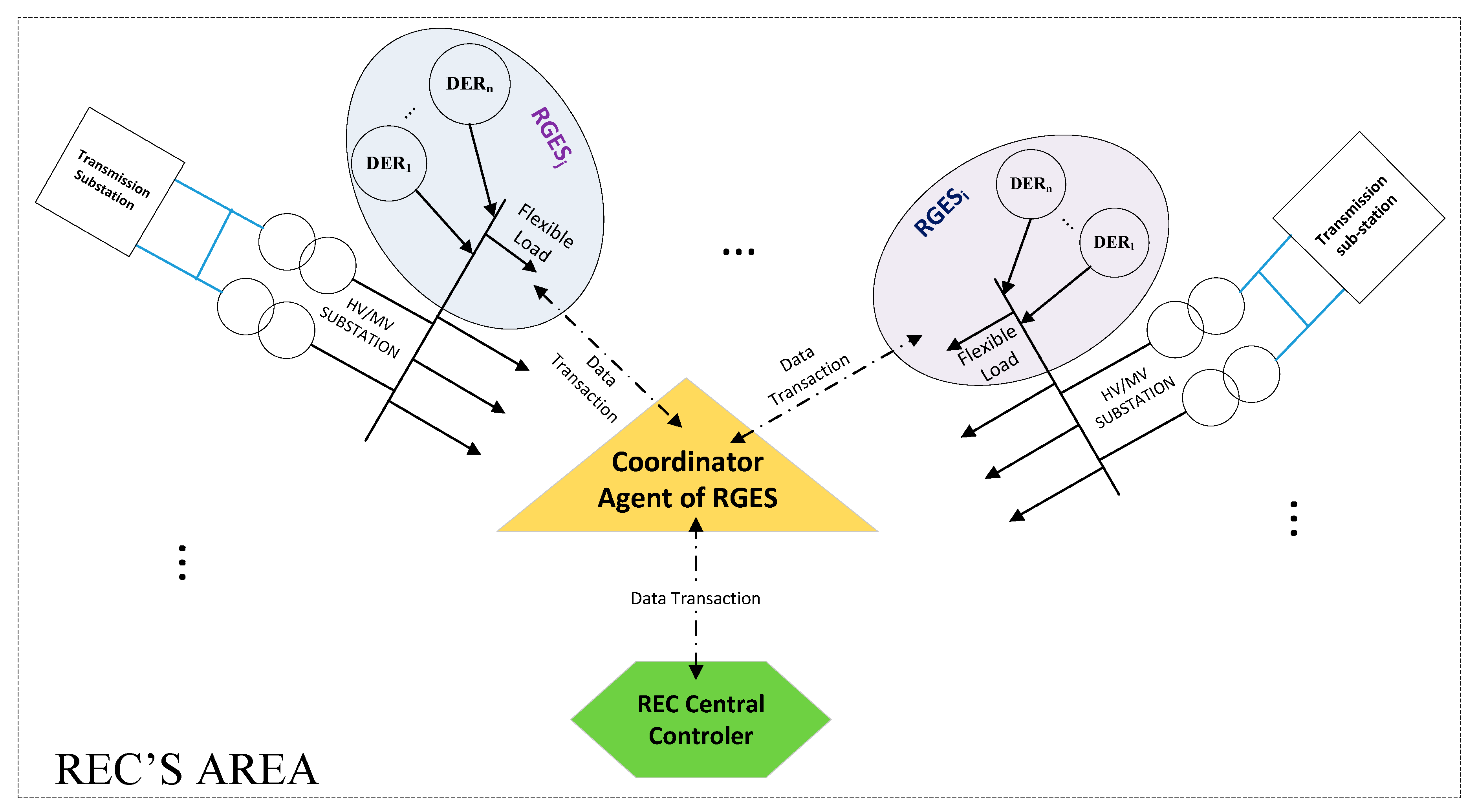
2.1. Regional Energy System (RGES)

The superiority of integrated energy systems over distributed generation sources is their greater controllability and visibility; they have a central coordinating agent and can facilitate the restructuring of the electricity industry from a centralized to a networked state. They can also, as an integrator of flexible loads, prevent the non-economic extension of the generation and sub-transmission networks over short periods of peak load. In the meantime, they can encourage small-cap private-equity partnerships to invest in the electricity industry. The RGES proposed in this study is configured as an energy network in a specific geographic region that is able to host a variety of renewable and non-renewable energy sources as well as flexible loads, representing a controllable entity in the power system. An RGES can be actively involved in the expansion planning of sub-transmission networks by investing in capacity addition and/or installation of new internal DERs. An investor in RGES can be a single entity or a number of private shareholders. An agent is referred to a coalition participant seeking to maximize the profit of the RGES.

2.2. Regional Electric Company (REC)

This paper assumes that RECs are responsible for supplying electricity for sub-transmission level consumers in a particular geographic region. They are also responsible for the expansion planning and operation of substations and lines at the sub-transmission and transmission voltage levels. Traditionally, they purchase electricity produced by large power plants and deliver it to the sub-transmission load centers. Therefore, in the traditional grid, their costs include the cost of purchasing energy from the upstream grid, the cost of energy losses, and costs incurred by substations and lines expansion planning programs. In the method we propose, in addition to purchasing power from upstream plants, REC can also purchase required energy from RGES’s resources. Here, it is also assumed that the costs of purchasing energy from upstream power plants and RGES’s resources are based on regulated tariffs. The purpose of REC is to minimize the related cost function.

3. Problem Formulation

3.1. First-Level Objective Function

At the first level, to get a maximized profit, RGES determines the optimal sizing and sitting of the resources in the local area considering time duration, the amount of load in each sub-transmission load center, the investments and operation costs of resources, the feed-in-tariff rate, the guaranteed purchase time, and geographic variables, such as irradiation and wind characteristics and flexible load behaviors. In fact, knowing the forecasted load in each load point in the planning horizon, an RGES is able to determine optimal site and size of its own resources in all sub-transmission substations (candidate site) to maximize its utility function according to Equation (1). Revenues include the present value of the energy sales to REC during the guaranteed purchase period, the energy sale to an REC after the guaranteed purchase period, and the salvaged revenue described in Equations (4)–(6). RGES’s costs include the present value of operation and investment costs, which are described by Equations (7) and (8).
O F R G E S = M a x { I C } ,
I = I T G + I A T G + I S A L ,
C = C O C + C I N V ,
I T G = i = 1 N T S k = 1 K t = 1 T τ = t t + T G k ( 1 + i r ) τ n = 1 N L D P t τ n k i × Π τ n k × T n τ ,
I A T G = i = 1 N T S k = 1 K t = 1 T τ = T G k t + 1 L F k ( 1 + i r ) τ n = 1 N L D P t τ n k i × Π τ n k × T n τ ,
I S A L = i = 1 N T S k = 1 K t = 1 T ( 1 + i r ) ( t + L F k ) × S A L k i ,
C O C = i = 1 N T S k = 1 K t = 1 T τ = 1 L F k t ( 1 + i r ) τ n = 1 N L D O C k i t τ ,
C I N V = t = 1 T ( 1 + i r ) t i = 1 N T S k = 1 K I C k i t .

Constraints of RGES

• Operational Constraint of RGES’s Resources
The generation of each unit within the RGES must be less than its nominal capacity.
0 P k n R G E S P k M a x R G E S ; k = 1 , 2 , , K ; n = 1 , 2 , , N L D ,
where P k j R G E S and S k j R G E S are the generated power and nominal power of the kth resource of each RGES in the nth level of the load duration curve (LDC) (MW), respectively. In this study, flexible loads have been also considered to be RGES resources, so the same constraint as in Equation (9) was applied to show the range in which responsive loads could react.
• Limitation of RGES Capacity
To enable the transfer of power generated by RGES’ s internal resource in single-event mode for the sub-transmission transformer of each substation, the maximum power generated by RGES that is fed to the sub-transmission network has to be limited to certain percentage according to Equation (10) [31]:
S R G E S i 0.5 S i T S . max + L min ,
where S i T S . max is the maximum transformer capacity of each sub-transmission substation determined in the expansion planning phase and Lmin is the minimum annual forecasted load in the planning horizon.

3.2. Second-Level Objective Function

At the second level, based on the results of sizing and sitting of RGES’s internal resources, REC applies load flow to get the amount of power required to be imported from the upstream network to satisfy the power balance constraint. It also determines energy loss cost and the costs related to the substation and lines’ expansion planning programs; and the cost function of the REC is ultimately determined. So, the objective function of REC is to minimize the total cost of REC subject to different constraints. This cost function can be considered as the combination of cost elements according to Equation (11):
O F R E C = M i n { S L L C + U G E C + S S E C + S L E C + R G E S E C }
In Equation (11), the economic assessment is made based on five terms, considering their current net values. SLLC is the transmission and sub-transmission lines’ losses obtained by Equation (12):
S L L C = t = 1 T ( 1 + i r ) t [ i = 1 N T S j = 1 N S S n = 1 N L D T n × L C × L i j S L × R i j S L × I i j n 2 +   j = 1 . j j N S S j = 1 . j j N S S n = 1 N L D T n × L C × L j j S L × R j j S L × I j j n 2 ]
The power losses in service transformers were neglected in this study as they are relatively low compared to the line losses.
UGEC is the cost of power purchased from the utility (i.e., transmission network) that can be calculated based on Equation (13). Generally, it is the REC who pays for the energy imported from the transmission network, which changes over the time based on the load duration curve (LDC). That cost is normally higher in peak hours and lower in other time intervals. The cost of providing energy by the transmission network is given by Equation (13):
U G E C = t = 1 T ( 1 + i r ) t i = 1 N T S n = 1 N L D P i n t G × T n t × π i n t G .
SSEC is the transmission and sub-transmission substation expansion cost obtained by Equation (14):
S S E C = t = 1 T ( 1 + i r ) t i = 1 N T S α i t T S × E C T S , i ( S T S , i t o l d , S T S , i t n e w ) + t = 1 T ( 1 + i r ) t j = 1 N S S α j t S S × E C S S , j ( S S S , j t o l d , S S S , j t n e w )
SLEC is the expansion cost for sub-transmission lines, as stated in Equation (15):
S L E C = t = 1 T ( 1 + i r ) t i = 1 N T S j = 1 N S S α i j t S L × E C T S L . i j t ( S T S L . i j t o l d . S T S L . i j t n e w ) + t = 1 T ( 1 + i r ) t j = 1 . j j N S S j = 1 . j j N S S α j j t T S L × E C S L . j j t ( S S L . i j t o l d . S S L . j j t n e w )
RGESEC is the cost of energy provision paid by the REC to the RGES given by Equation (16):
R G E S E C = j = 1 N S S k = 1 K t = 1 T τ = 1 T G k t ( 1 + i r ) τ n = 1 N L D P t τ n k j × Π τ n k × T n τ
Once the total number of guaranteed purchase years is over, the energy produced by RGES’s units (including DERs and services offered by flexible loads/DR programs) is no longer priced on feed-in-tariff basis but according to upstream network tariffs.

REC Constraints

• Line Loading Constraints
The loading of transmission and sub-transmission lines must be lower than their thermal capacity, as formulated in Equations (17) and (18):
| I i j T S L | 0.8 | I i j . max T S L | ; i { 1 , 2 , , N T S } . j { 1 , 2 , , N S S }
| I j j S L | 0.8 | I j j . max S L | ; j { 1 , 2 , , N S S } . j { 1 , 2 , , N S S } . j j .
In this paper, it is assumed that maximum permitted current of each transmission and sub-transmission line is 80% of lines thermal capacity [7].
• Sub-Transmission Substations Constraints
The loading of sub-transmission substations must be lower than their thermal capacity, as given in Equation (19):
j = 1 N L P γ i j l p S j L P ( 1 r f 1 ) × S i S S , max ; i { 1 , 2 , , N S S }
According to Equation (19), the allocated load to each substation is lower than the capacity of that substation. However, considering the reserve factor results in a higher network reliability.
• Transmission Substations Constraints
The load of transmission substations must be lower than their thermal capacity, as provided in Equation (20):
j = 1 N S S γ i j S S S i S S ( 1 r f i ) × S i T S . max ; i { 1 , 2 , , N S S } ,
where γ i j S S is the binary variable set to 1 if the sub-transmission substation j is supplied from the ith transmission substation, and 0 otherwise.
• Power balance constraint
In each time interval and each LDC segment, the following demand-supply balance constraint must be met:
k = 1 K P k R G E S + P t r = j = 1 J P L o a d j + P L o s s ,
where P k R G E S is the power generated by RGES in each time and Ptr is transaction power with other networks.

4. Solution Procedure

4.1. Multiobjective Particle Swarm Optimization (MOPSO)

MOPSO was presented in 2004 by Coello et al. [32]. This algorithm is population-based, and uses a geographically-based approach to maintain diversity. As it introduces external archiving, crowding distance, and a mutation operator, MOPSO uses a measure of performance similar to the fitness value used by evolutionary algorithms, and the adjustments of individuals are analogous to the use of a crossover operator. The algorithm updates the velocity and the position of each particle according to global bests of particles gained from last iteration; and mutation is carried out among individuals. Regarding the performance evaluation of MOPSO, authors in [33] conducted a comparative study among several multi-criteria problem-solving algorithms. The quality of the Pareto sets (in terms of distance, distribution, and extent) was presented accordingly to analyze the performance of algorithms. It was shown that MOPSO multiplies the chances to keep individuals’ changes and make it easier to maintain diversity compared to non-dominated sorting genetic algorithm II (NSGA-II). Additionally, the MOPSO method is faster at getting convergence compared to NSGA-II. Due to its design simplicity and effectiveness, MOPSO was also utilized in this study to solve the proposed bi-level optimization mode considering different technical constraints and regulatory frameworks. A typical MOPSO flowchart together with its building blocks and key functions are presented in [34,35].

4.2. Fuzzy Satisfying Method (FSM)

In this paper, a number of fuzzy sets were defined for all of the RGES’s profit functions and REC’s costs we calculated according to Equations (22) and (23), respectively. It was assumed that maximum and minimum values of profit functions of RGES (i.e., P F i max and P F i min ) and cost functions (i.e., C j max and C j min ) of REC could be predicted. When the individual’s profit and cost range are taken into account, the membership function μ(PF) and μ(C) for each objective function can be determined by Equations (22) and (23) [36]:
μ ( P F R G E S ) = { 0          P F R G E S   P F R G E S min P F R G E S P F R G E S min P F R G E S max P F R G E S min     P F R G E S min P F R G E S P F R G E S max 1          P F R G E S P F R G E S max
μ ( P F R E C ) = 1 μ ( C R E C ) .
The minimum value for all membership functions of a specific set represents the optimal value of that set. A set with larger minimum value of membership functions is more favorable, since it satisfies more objective functions in terms of individual optimum values. In case of multiple objective functions, the optimal solution (i.e., the equilibrium) can be realized by Equation (24):
M a x   ψ = M a x { min ( μ ( P F ) m ) }    m = 1 , , M ,
where m is the MOPSO archive member’s counter and M is the number of MOPSO archive members. According to Equation (24), an optimal plan for RGES and REC would be a combination in which ψ has the highest value.

4.3. Solution Procedure Description

In the proposed bi-level and bi-objective sub-transmission expansion planning, considering an aggregated energy system, initially, RGES obtains basic information, including estimations of different load levels in the planning horizon; the locations of load centers, current transmission, and sub-transmission lines; and substation information from the system operator. In this work, it was assumed that load centers are concentrated in the outgoing feeders of the sub-transmission substations. Additionally, sub-transmission and RGES expansion planning were considered based on the anticipated peak load in the planning horizon. And, due to the short duration of peak load duration, for achieving economic planning, a percentage of the planning program is executed on the basis of flexible loads by RGES. This paper assumes that 10% of the predicted peak load can be managed by flexible loads. In the first level of the proposed planning model, RGES randomly distributes its internal resource capacity among the load centers. Due to operational constraints and considering the single contingency mode for the transformer capacity of sub-transmission substation, according to Equation (10), the maximum internal resource capacity of RGES in each sub-transmission substation is considered to be half of the corresponding transformer capacity plus the minimum annual load of that substation. At the second level, according to the network constraint (Equations (17)–(21)) and the random sizing and siting of RGES’s internal resources, the REC applies a load flow program to quantify the amount of energy losses, the energy that must be purchased from the upstream network to maintain the power balance equation (Equation (21)), and the lines required and substation expansion planning. Afterwards, at the end of each iteration, OFRGES and OFREC are calculated according to Equations (1) and (11) and are stored in the MOPSO archive. OFRGES and OFREC are the RGES’s profit function and REC’s cost function, respectively. This bi-level process is repeated until the termination criteria are met and non-dominated responses are stored in the archive. Finally, by using the fuzzy satisfying method (FSM), the equilibrium point of RGES and sub-transmission expansion planning are determined.
Obviously, the higher the number of repetitions, the greater the likelihood of an optimal global response. Figure 2 shows the flowchart of the method.

5. Simulations and Test Results
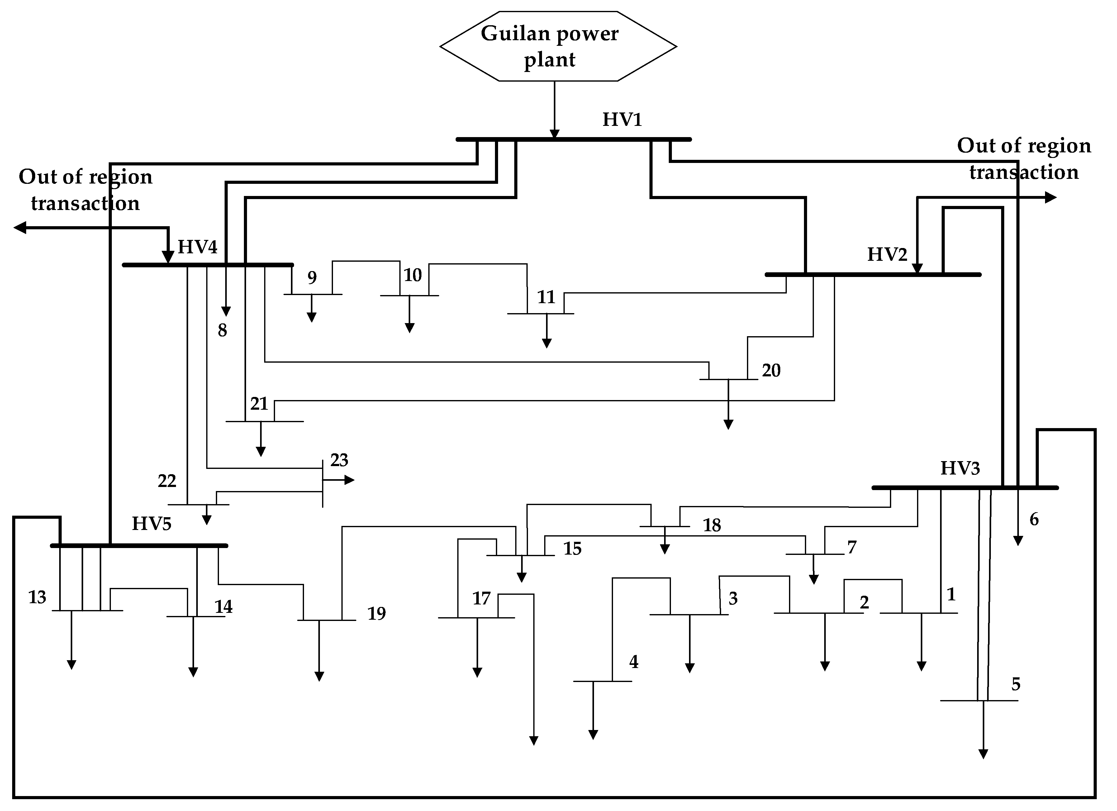
5.1. Input Data

To investigate the effectiveness of the proposed method, the representative sub-transmission system of Guilan Regional Electrical Company located in north of Iran was used as a test case. This electrical network includes twenty-three 63/20 kV sub-transmission substations. In this research, it was assumed that all load points were located in the existing sub-transmission substations. The 63/20 kV substations are fed by five 230/63 kV transmission substations. The single line diagram of the case study is depicted in Figure 3 and its details are given in Appendix A and Appendix B.
The annual load growth in all levels of LDC was assumed to be 7%. Each sub-transmission line has a capacity of 50 MW. The reserve factors for the lines and substation were supposed 20% and 30%, respectively [36], and the maximum constructible circuits of the lines at the corridors are 4. The number of study years in the expansion planning problem was chosen to be 5. Other requisite information is provided in Table 1.
To study the effects of RGES on sub-transmission expansion planning, two different cases were considered as follows:
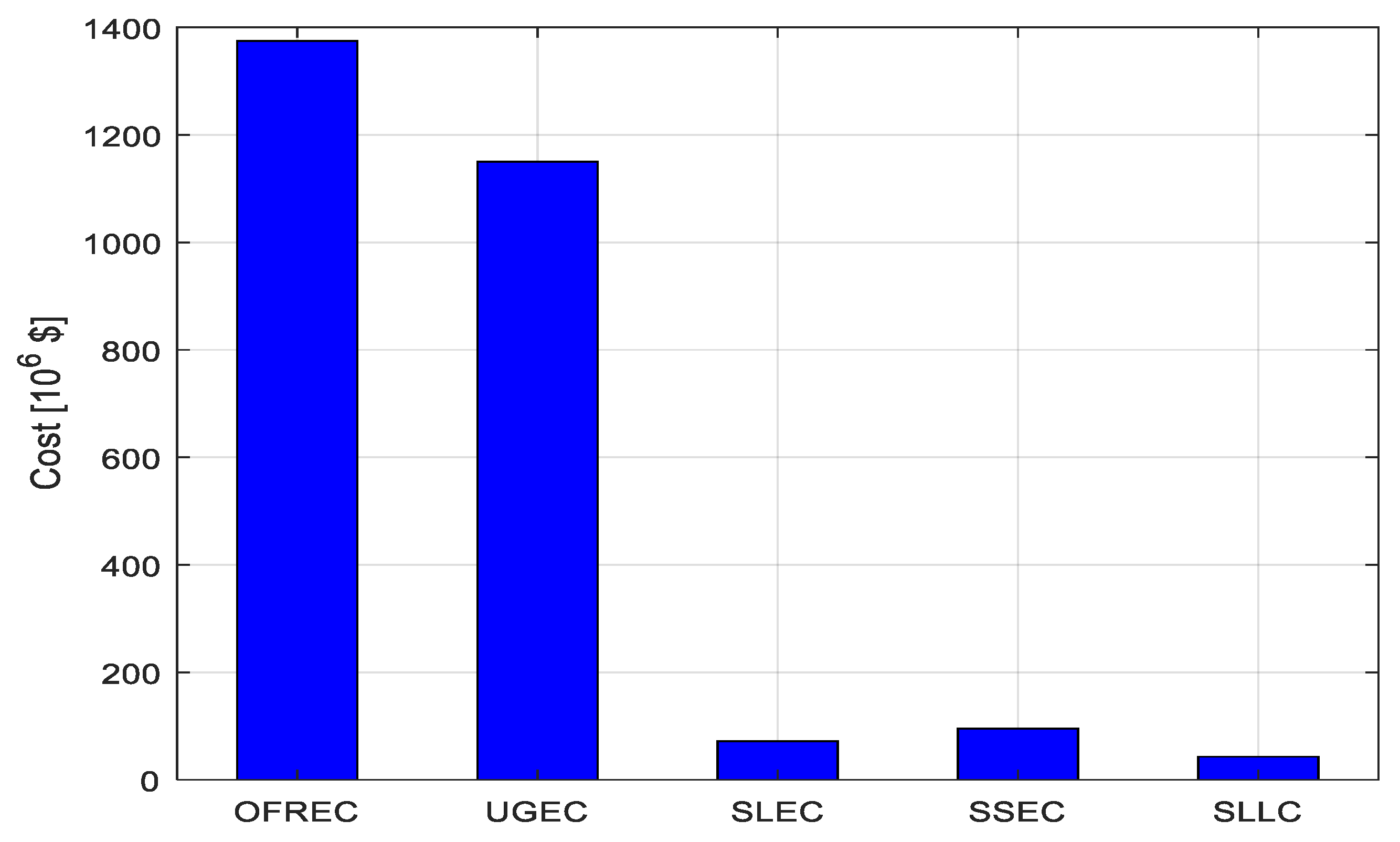
  • Base case (traditional sub-transmission expansion planning method): There are no RGES units installed in the local area and the load of the sub-transmission system is totally supplied by the transmission network. This case represents the traditional sub-transmission network model where there is no contribution from local energy sources. Additionally, the optimal expansion planning model for such a network should primarily consider OFREC as an objective.
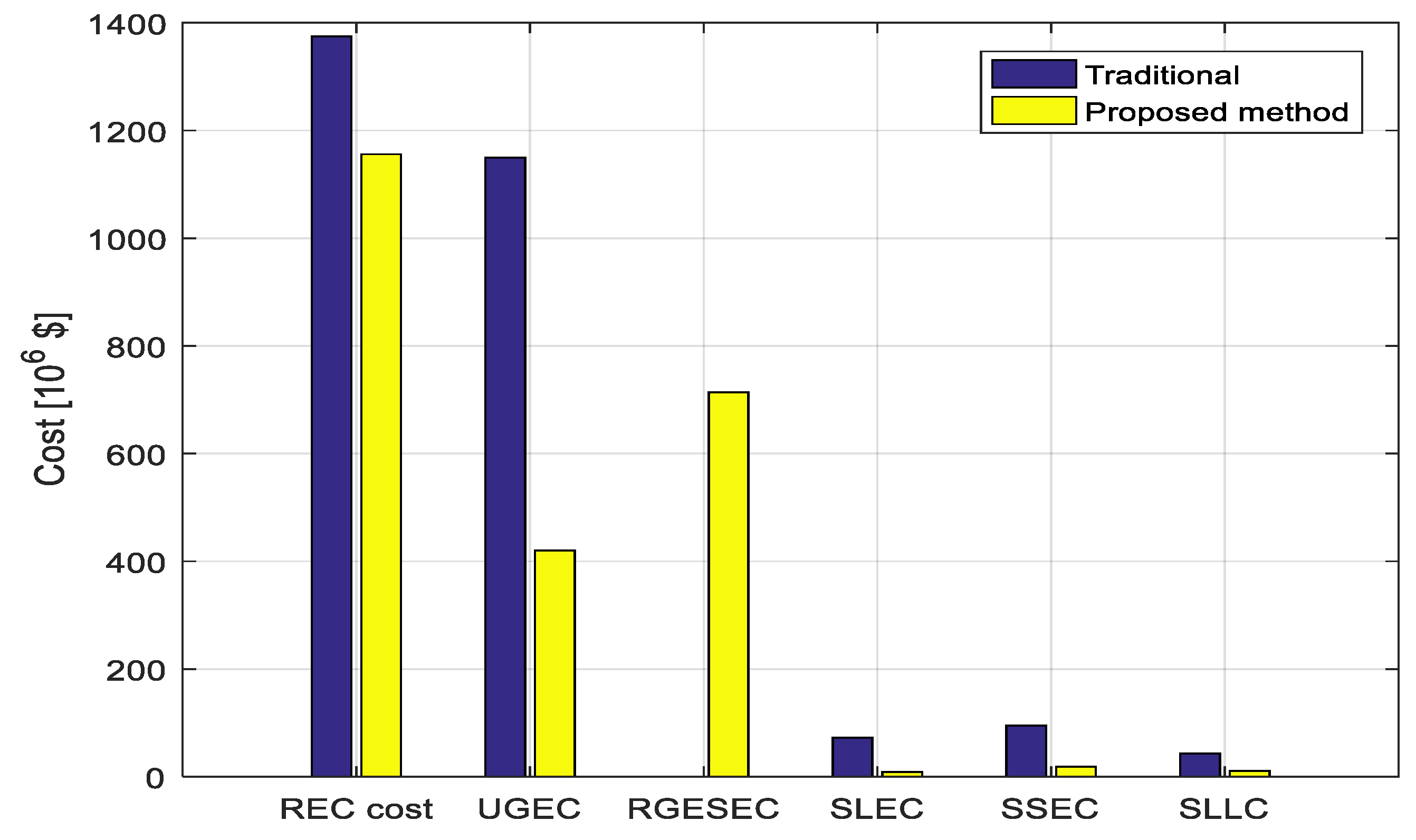
  • Case 2 (the proposed method): In this case, for the base case network, instead of the traditional method, the bi-level approach proposed in this paper is utilized and the results are compared with the results of traditional method for validating the new approach.
In Table 2 and Table 3, data requirements for the technical and economic evaluations of the sub-transmission expansion planning model and MOPSO parameters are provided, respectively. Real information of the test system we examined was used for both case studies.

5.2. Discussion

Results of the optimal expansion planning in each case study are included in Table 4 in terms of different objectives and cost/benefit components. Obviously, incorporation of RGES resources into the expansion planning model could not only decrease overall system losses, but also mitigate the costs of lines and substations expansion, and the energy purchased from the transmission network.
It can be observed from simulation results that the main cost component in a traditional expansion plan (base case) relates to the UGEC (Figure 4). The results of the second case study are tabulated in the other rows of Table 4. By solving the proposed two-objective optimization problem using an MOPSO algorithm, a set of non-dominated solutions were found.
The Pareto front of optimal solutions for the problem, which are stored in a finite-sized repository, is shown in Figure 5. As observed, the proposed multi-criteria optimization model yields a valid and well-distributed set of Pareto-optimal solutions, providing the system planers (e.g. REC and RGES owners) various options to select an appropriate expansion plan according to economic and/or technical considerations. As an illustrative example, in Guilan Regional Electric Company’s network, which is our real test case in this study, the total cost of a given expansion plans can be very different according to several factors, such as large-scale land acquisitions and leases, weather conditions, and legal considerations. These factors can push an expansion plan to a highly expensive and time-consuming point or even to the verge of infeasibility. Getting back to the results shown in Table 4, it is understood that, although the first point in the Pareto set, named Pareto (1) herein, involves the smallest cost for REC, it denotes the most extensive lines expansion plan, which enforces the least profit for the RGES, accordingly. On the other hand, Pareto (2) shows a situation where the expansion plan results in a maximum OFRGES for the RGES and low SLEC and SSEC. In Pareto (2), SLLC is also a minimum that is good for the REC. Pareto (7) presents the maximum losses, lines and substations expansion costs, and least profit for the RGES, which is not favorable for the RGEC and Guilan Regional Electric Company. In the next sub-section, fuzzy satisfying and the max-min method are used to determine the economic equilibrium point according to the Equations (22)–(24).

5.3. Applying the Fuzzy Satisfying Method for Evaluating MOPSO’s Archive

The simulation results of the traditional and proposed methods for sub-transmission expansion planning were analyzed in the previous subsection. In this subsection, apart from the constituent elements of the OFRGES and OFREC, the equilibrium point of investment in view point of RGES and REC’s investor were obtained using the FSM method described in Section 3.2. Using Equations (22) and (23), the fuzzy values of RGES profits and REC costs are provided in Table 5 and Table 6.
Using Equation (24), Pareto (10) is the equilibrium point for RGES and REC. However, as explained in Section 4.2, depending on the degree of importance of the OFRGES and OFREC components and other specific conditions of RGES and REC, another Pareto point could also be considered for expansion planning.
Figure 6 shows a comparison between the expansion costs of substations and lines, and the loss cost in the traditional expansion planning model and the proposed method (conducted for Pareto (10)). It was observed that a joint expansion planning model could decrease the costs of lines and substations’ expansions and losses by 88%, 80%, and 74%, respectively, in comparison with the traditional method.

6. Conclusions

The aim of this paper was to propose an efficient, bi-level expansion-planning method considering the regional energy system (RGES) at sub-transmission level. The RGES could not only participate in the sub-transmission grid expansion planning, but also contribute to energy provision services in the long term.
The proposed bi-level planning process with all system constraints was presented as an optimization model with two objectives, including different cost-profit components. Through a real test system and using computer simulations in two different approaches (traditional and proposed methods), the effectiveness of the approach we proposed was demonstrated. Results showed that expansion planning of sub-transmission grid considering RGES could significantly reduce power loss cost, costs of lines’ and substation expansions, and the total cost of a given REC while accruing profits for RGES. Additionally, given the relative importance of the RGES’s cost function elements, it is possible to decide the conditional decision making from non-dominated responses.
The extension of this work will mainly consider the effect of uncertainties, such as the impact of the uncertainty of renewable energy units of RGESs on making expansion plans. Contingency analysis in the presence of RGES will also be an aspect of future work.

Author Contributions

Conceptualization, S.M.M.T., M.N., and A.A.-M.; data curation, M.N.; formal analysis, S.M.M.T., M.N., and A.A.-M.; funding acquisition, A.A.-M.; investigation, S.M.M.T., M.N., and A.A.-M.; methodology, S.M.M.T., M.N., and A.A.-M.; project administration, S.M.M.T. and A.A.-M.; resources, M.N.; software, M.N. and A.A.-M.; supervision, S.M.M.T., M.N., and A.A.-M.; validation, S.M.M.T., M.N., and A.A.-M.; visualization, M.N.

Funding

This research received no external funding.

Conflicts of Interest

The authors declare no conflict of interest.

Nomenclature

Sets
TNumber of years in the planning horizon.LijThe total length of sub-transmission line along the ij path (km)
NTSNumber of transmission substations.IijCurrent flowing through the lines in ij path (A)
NSSNumber of sub-transmission substations.T(.)Time duration of each load level
NLDNumber of load levels.TGThe number of years electricity is purchased at a regulated tariff by the regional electric Company
KNumber of sources in a RGES.ПGElectricity price for energy purchasing from upstream utility (Transmission grid)
Indices ПkElectricity price for energy purchasing from regional energy system’s resources
tTime index, t = {1, …, T}ECTS (STSold, STSnew) The cost of upgrading the capacity of transmission substation j from STSold to STSnew
iTransmission subscript index, i = {1, …, NTS}ECSS (SSSold, SSSnew) The cost of upgrading the capacity of sub-transmission substation i from SSSold to SSSnew
j, j’Sub-transmission subscript indices, j, j’ = {1, …, NSS}ECSL (SSLold, SSLnew)The cost of upgrading the capacity of sub-transmission line i from SSLold to SSLnew
nTime duration index, n = {1, 2 …, NLD}ECTSL (STSLold, STSLnew)The cost of upgrading the capacity of transmission line j from STSLold to STSLnew
kEnergy source index in each regional energy system, k = {1, …, K}ПGElectricity price for energy purchasing from upstream utility (Transmission grid)
τGuaranteed year subscript index, τ = {1, …, TG}ПkElectricity price for energy purchasing from RGES’s resources
PopPopulation subscript index, Pop = {1, …, Popsize}rfThe reserve factor of substation which is a number between 0 up to 1
Parameters LFkThe life time of the kth resource in a RGES
irInterest rateICk Installation cost of the kth source in a RGES
OFRGESRGES’s profit functionOCkOperation cost of the kth source in a RGES
IRGES’s incomeSALkSalvage value of the kth resource in a RGES
CRGES’s costPtrTotal power transaction between considered region and other regions
ITGRGES’s revenue in the guaranteed purchase period PRGESGenerated power by RGES’ s resources
IATGRGES’s revenue after the guaranteed purchase periodSjLPThe power demand of the jth load point
ISALSalvage revenueSTSmaxMaximum transformer capacity of transmission substation
COCOperational costRijThe resistance of sub-transmission line along the ij path (Ohm/km)
CINVInvestment costSSSTransformer capacity of sub-transmission substation
OFRECREC’s cost functionSLSub-transmission Line
CSLLCCost of transmission/sub-transmissions lines lossesVariables
CUGECCost of the purchased power from the utility (i.e., transmission network),PGImported power from transmission grid into sub-transmission grid
CSSECCost of transmission/sub-transmission substations’ expansion,PkPurchased power from the kth sources of RGES
CSLECExpansion cost of sub-transmission linesPLOSSPurchased power from the kth sources of RGES
CRGESESCost of energy provision paid by the REC to the RGESαSL, αTSL, αTS, αSS, ϒLP, ϒSSBinary variables
LCLoss cost factor ($/MWh)

Appendix A

Table A1. Specification of substations and loads.
Substation (bus #)Voltage Level
(kV)
Existing Capacity
(MVA)
Extendable capacity
(MVA)
Peak-Load in Base Year (MW)Mid-Load in Base Year (MW)Low-Load in Base Year (MW)
163/202*303*30401910
263/202*30+153*30503817
363/202*403*40422815
463/202*403*4018117
563/202*403*4018127
663/201*302*3024276
763/202*152*3024176
863/201*152*151383
963/202*152*3019114.5
1063/202*152*30302218
1163/202*303*30362311
1263/202*403*4034189.5
1363/202*403*40664517
1463/202*303*3048248
1563/202*30+1*203*40614017
1663/202*303*30563517
1763/202*403*4066.55119
1863/202*403*40624818
1963/202*303*30583613
2063/202*403*4030188
2163/202*303*30603417
2263/202*403*40452110

Appendix B

Table A2. Specification of corridors.
CorridorLength (km)Capacity
(MVA)
Extendable Capacity (MVA)CorridorLength (km)Capacity
(MVA)
Extendable Capacity (MVA)
HV3-119.551*502*50HV5-1323*504*50
1-29.831*502*5013-1410.21*502*50
2-34.21*502*50HV4-229.11*502*50
3-47.21*502*50HV4-23111*502*50
HV3-513.362*503*5022-2391*502*50
HV3-1810.51*502*50HV4-21111*502*50
HV3-75.791*502*50HV4-921*502*50
7-155.51*502*50HV4-206.31*502*50
18-153.91*502*509-104.51*502*50
15-174.81*502*5010-1151*502*50
15-1991*502*50HV2-1111*502*50
HV5-1981*502*50HV2-21111*502*50
HV5-147.81*502*50HV2-2012.51*502*50

References

  1. Fang, X.; Misra, S.; Xue, G.; Yang, D. Smart Grid—The New and Improved Power Grid: A Survey. IEEE Commun. Surv. Tutor. 2011, 14, 944–980. [Google Scholar] [CrossRef]
  2. Sepasian, M.; Seifi, H.; AkbariForoud, A.; Hosseini, S.; Kabir, E.; Foroud, A. A New Approach for Substation Expansion Planning. IEEE Trans. Power Syst. 2006, 21, 997–1004. [Google Scholar] [CrossRef]
  3. Rad, H.K.; Moravej, Z. An approach for simultaneous distribution, sub-transmission, and transmission networks expansion planning. Int. J. Electr. Power Energy Syst. 2017, 91, 166–182. [Google Scholar]
  4. Rad, H.K.; Moravej, Z. Coordinated transmission substations and sub-transmission networks expansion planning incorporating distributed generation. Energy 2017, 120, 996–1011. [Google Scholar]
  5. Jalali, M.; Zare, K.; Hagh, M.T. A multi-stage MINLP-based model for sub-transmission system expansion planning considering the placement of DG units. Int. J. Electr. Power Energy Syst. 2014, 63, 8–16. [Google Scholar] [CrossRef]
  6. Asensio, M.; Munoz-Delgado, G.; Contreras, J. A Bi-level Approach to Distribution Network and Renewable Energy Expansion Planning considering Demand Response. IEEE Trans. Power Syst. 2017, 32, 4298–4309. [Google Scholar] [CrossRef]
  7. Shayeghi, H.; Bagheri, A. Dynamic sub-transmission system expansion planning incorporating distributed generation using hybrid DCGA and LP technique. Int. J. Electr. Power Energy Syst. 2013, 48, 111–122. [Google Scholar] [CrossRef]
  8. Jain, N.; Singh, S.N.; Srivastava, S.C. Particle swarm optimization based method for optimal siting and sizing of multiple distributed generators. In Proceedings of the 16th National Power Systems Conference, Hyderabad, India, 15–17 December 2010. [Google Scholar]
  9. Seethapathy, R.; Atwa, Y.; El-Saadany, E.; Salama, M. Optimal Renewable Resources Mix for Distribution System Energy Loss Minimization. IEEE Trans. Power Syst. 2009, 25, 360–370. [Google Scholar]
  10. Bagheri, A.; Monsef, H.; Lesani, H. Integrated distribution network expansion planning incorporating distributed generation considering uncertainties, reliability, and operational conditions. Int. J. Electr. Power Energy Syst. 2015, 73, 56–70. [Google Scholar] [CrossRef]
  11. Khayatian, A.; Barati, M.; Lim, G.J. Integrated Microgrid Expansion Planning in Electricity Market with Uncertainty. IEEE Trans. Power Syst. 2017, 33, 3634–3643. [Google Scholar] [CrossRef]
  12. Moreira, A.; Pozo, D.; Street, A.; Sauma, E. Reliable Renewable Generation and Transmission Expansion Planning: Co-Optimizing System’s Resources for Meeting Renewable Targets. IEEE Trans. Power Syst. 2016, 32, 3246–3257. [Google Scholar] [CrossRef]
  13. Hemmati, R.; Hooshmand, R.-A.; Khodabakhshian, A. Comprehensive review of generation and transmission expansion planning. IET Gener. Transm. Distrib. 2013, 7, 955–964. [Google Scholar] [CrossRef]
  14. Vahedipour-Dahraie, M.; Rashidizadeh-Kermani, H.; Anvari-Moghaddam, A. Risk-Constrained Stochastic Scheduling of a Grid-Connected Hybrid Microgrid with Variable Wind Power Generation. Electronics 2019, 8, 577. [Google Scholar] [CrossRef]
  15. Luo, F.; Yang, J.; Dong, Z.Y.; Meng, K.; Wong, K.P.; Qiu, J. Short-term operational planning framework for virtual power plants with high renewable penetrations. IET Renew. Power Gener. 2016, 10, 623–633. [Google Scholar] [CrossRef]
  16. Khodaei, A.; Shahidehpour, M. Microgrid-Based Co-Optimization of Generation and Transmission Planning in Power Systems. IEEE Trans. Power Syst. 2012, 28, 1582–1590. [Google Scholar] [CrossRef]
  17. Moghaddas Tafreshi, S.M.; Navidi, M. Economic Expansion Planning of Sub-Transmission Grid and Regional Virtual Power Plant. J. Energy Manag. Technol. 2019, 3, 65–74. [Google Scholar]
  18. Vatani, B.; Chowdhury, B.; Lin, J. The role of demand response as an alternative transmission expansion solution in a capacity market. In Proceedings of the IEEE Industry Applications Society Annual Meeting, Cincinnati, OH, USA, 1–5 October 2017. [Google Scholar]
  19. Garcia-Bertrand, R.; Minguez, R. Dynamic Robust Transmission Network Expansion Planning. IEEE Trans. Power Syst. 2016, 32, 2618–2628. [Google Scholar] [CrossRef]
  20. Roh, J.H.; Shahidehpour, M.; Fu, Y. Market-Based Coordination of Transmission and Generation Capacity Planning. IEEE Trans. Power Syst. 2007, 22, 1406–1419. [Google Scholar] [CrossRef]
  21. Tafreshi, S.M.M.; Lahiji, A.S. Long-Term Market Equilibrium in Smart Grid Paradigm with Introducing Demand Response Provider in Competition. IEEE Trans. Smart Grid 2015, 6, 2794–2806. [Google Scholar] [CrossRef]
  22. Lahiji, A.S.; Tafreshi, S.M.M. Merchant transmission planning in smart paradigm with introducing demand response aggregator in wholesale market. Int. Trans. Electr. Energy Syst. 2016, 26, 2148–2171. [Google Scholar] [CrossRef]
  23. Asadzadeh, V.; Golkar, M.A.; Moghaddas-Tafreshi, S.M. Economics-based transmission expansion planning in restructured power systems using decimal codification genetic algorithm. In Proceedings of the IEEE Jordan Conference on Applied Electrical Engineering and Computing Technologies (AEECT), Amman, Jordan, 6–8 December 2011; pp. 1–8. [Google Scholar]
  24. Gan, W.; Ai, X.; Fang, J.; Yan, M.; Yao, W.; Zuo, W.; Wen, J. Security constrained co-planning of transmission expansion and energy storage. Appl. Energy 2019, 239, 383–394. [Google Scholar] [CrossRef]
  25. Sardou, I.G.; Azad-Farsani, E. Network expansion planning with microgrid aggregators under uncertainty. IET Gener. Transm. Distrib. 2018, 12, 2105–2114. [Google Scholar] [CrossRef]
  26. Antunes, C.H. Multiobjective Optimization in the Energy Sector: Selected Problems and Challenges. In Economic Dynamics; Springer Science and Business Media LLC: Berlin/Heidelberg, Germany, 2019; pp. 357–370. [Google Scholar]
  27. Khan, I. Power generation expansion plan and sustainability in a developing country: A multi-criteria decision analysis. J. Clean. Prod. 2019, 220, 707–720. [Google Scholar] [CrossRef]
  28. Behera, S.R.; Panigrahi, B.K. A multi objective approach for placement of multiple DGs in the radial distribution system. Int. J. Mach. Learn. Cybern. 2019, 10, 2027–2041. [Google Scholar] [CrossRef]
  29. Hlal, M.I.; Ramachandaramurthya, V.K.; Padmanaban, S.; Kaboli, H.R.; Pouryekta, A.; Abdullah, T.A.R.B.T. NSGA-II and MOPSO Based Optimization for Sizing of Hybrid PV/Wind/Battery Energy Storage System. Int. J. Power Electron. Drive Syst. 2019, 10, 463–478. [Google Scholar] [CrossRef]
  30. Zhang, J.; Cho, H.; Mago, P.J.; Zhang, H.; Yang, F. Multi-Objective Particle Swarm Optimization (MOPSO) for a Distributed Energy System Integrated with Energy Storage. J. Therm. Sci. 2019, 28, 1221–1235. [Google Scholar] [CrossRef]
  31. Available online: http://www.tavanir.org (accessed on 17 April 2016).
  32. Coello, C.C.; Lechuga, M.S. MOPSO: A proposal for multiple objective particle swarm optimization. In Proceedings of the Congress on Evolutionary Computation. CEC’02 (Cat. No.02TH8600), Honolulu, HI, USA, 12–17 May 2002. [Google Scholar]
  33. Wöhling, T.; Vrugt, J.A.; Barkle, G.F. Comparison of Three Multiobjective Optimization Algorithms for Inverse Modeling of Vadose Zone Hydraulic Properties. Soil Sci. Soc. Am. J. 2008, 72, 305. [Google Scholar] [CrossRef]
  34. Anvari-Moghaddam, A.; Seifi, A.; Niknam, T. Multi-operation management of a typical micro-grids using Particle Swarm Optimization: A comparative study. Renew. Sustain. Energy Rev. 2012, 16, 1268–1281. [Google Scholar] [CrossRef]
  35. Anvari-Moghaddam, A.; Seifi, A.; Niknam, T.; Pahlavani, M.R.A. Multi-objective operation management of a renewable MG (micro-grid) with back-up micro-turbine/fuel cell/battery hybrid power source. Energy 2011, 36, 6490–6507. [Google Scholar] [CrossRef]
  36. Foroud, A.A.; Amirahmadi, M.; Bahmanzadeh, M.; Abdoos, A.A. Optimal bidding strategy for all market players in a wholesale power market considering demand response programs. Eur. Trans. Electr. Power 2011, 21, 293–311. [Google Scholar] [CrossRef]
Figure 1. Schematic diagram of the integrated sub-transmission grid we propose, with a single regional energy system (RGES).
Electronics 08 01416 g001
Figure 2. Flowchart of the proposed method.
Electronics 08 01416 g002
Figure 3. Single line of the case study.
Electronics 08 01416 g003
Figure 4. Traditional planning cost components.
Electronics 08 01416 g004
Figure 5. Pareto front diagram.
Electronics 08 01416 g005
Figure 6. A comparison of the elements of the traditional and proposed methods.
Electronics 08 01416 g006
Table 1. Data requirements for the simulation [31].
ParameterValueParameterValue
Interest rate (%)5Duration of night low-load(h)1500
Number of planning years5Duration of day peak-load(h)600
Annual growth rate of the guaranteed purchase (%)7Duration of day mid-load(h)2260
Maximum allowed voltage drop 5Duration of day low-load(h)1000
Maximum RGES’s resources penetration (%)50Transmission electricity price in the peak-load level ($/MWh)50
Installation cost of DG units ($/MW) 200,000Transmission electricity price in the mid-load level ($/MWh)30
Operating cost of DG units ($/MWh) 25Transmission electricity price in the low-load level ($/MWh)20
RGEC electricity price in the peak-load level ($/MWh)60Cost of DR in the peak-load level ($/MWh)80
RGEC electricity price in the mid-load level ($/MWh)35Cost of DR in the mid-load level ($/MWh)40
RGEC electricity price in the low-load level ($/MWh)25Cost of DR in the low-load level ($/MWh)30
Duration of night—peak load(h)400Penalty cost of load loss in sub-transmission ($/MWh) 15.22
Duration of night—mid load(h)3000
Table 2. Technical and economic data used to create the sub-transmission expansion planning model [31].
ParameterValue
Secondary voltage of sub-transmission substation (KV) 20
Cost of transformer capacity increment ($/MVA)12,500
Cost of each MV bay installation (with maximum capacity of 7 MW) ($)2850
Cost of each HV (63 kV) bay installation (with maximum capacity of 50 MVA) ($)285,000
Cost of 63 kV overhead line extension with 50 MVA capacity ($/km)80,000
Cost of 230 KV overhead line extension with 250 MVA capacity ($/km)200,000
Table 3. MOPSO Parameters.
ParameterValue
Number of iterations100
Number of population200
Repository size10
Inertia coefficient0.5
Mutation rate0.5
C11.5
C22
Table 4. Summary of the simulation results.
[Prices Are in Dollars]OFREC
(*106)
OFRGES
(*106)
Line Cost (SLEC)
(*106)
Substation Cost (SSEC)
(*106)
Loss Cost (SLLC)
(*106)
(UGEC)
(*106)
Base case
(Traditional)
137507295431150
Pareto (1)10722961218.7911.64678.5
Pareto (2)13507844.989.7410.33343.3
Pareto (3)11975248.7610.4310.85534
Pareto (4)11704815.6310.4911.18558
Pareto (5)114042552.1611.5311.13602
Pareto (6)13277434.789.5510.31399
Pareto (7)10923301319.5811.28655.7
Pareto (8)13097144.989.1810.6420
Pareto (9)12135448.5510.8610.8418
Pareto (10)11564428.5618.6010.91569
Table 5. Membership value of Pareto (1) to Pareto (5).
Pareto (1)Pareto (2)Pareto (3)Pareto (4)Pareto (5)
(μ(PF), μ(C)) (0.8, 0.37)(0.1, 0.98)(0.47, 0.65)(0.54, 0.6)(0.63, 0.53)
Table 6. Membership value of Pareto (6) to Pareto (10).
Pareto (6)Pareto (7)Pareto (8)Pareto (9)Pareto (10)
(μ(PF), μ(C)) (0.13, 0.93)(0.75, 0.41)(0.18, 0.89)(0.43, 0.68)(0.58, 0.55)

