1. Introduction
Microwave photonic link (MPL), microwave transmission over an optical fiber, or radio over fiber (RoF) are considered as good solutions for high speed wireless transmission [
1,
2,
3,
4,
5,
6,
7,
8,
9,
10] due to its low cost, its simple system architecture, its anti-interference, its large bandwidth, its low transmission loss, and its low power consumption. With the increase of new optical communication system [
11,
12,
13,
14] services, the ultra-high speed and high spectrum efficiency have become primary demands for improving microwave photonic transmission. In order to reach these goals, advanced modulation formats and optical coherent demodulation are employed [
15,
16,
17,
18,
19,
20,
21,
22]. However, the sophisticated coherent modulation and demodulation technology increase the complexity of the remote unit, which is contradictory to our objective of using a simplified and low-cost optical remote unit. Consequently, direct optoelectronic demodulation can be considered as the first choice under the condition of same transfer rate.
In [
23], X. Xue, W. JI, K. Huang, X. Li, and S. Zhang propose a simplified architecture with the use of the direct optoelectronic demodulation. However, the modulation format of orthogonal frequency division multiplexes (OFDM) aggravates peak-to-average-power ratio (PAPR).
In [
24], H. Huang, C. Lin, Y. Chiang, C. Wei, and C. Ho employ the single-sideband modulation to decrease the chromatic dispersion in a MPL. In [
25], C. Lin, C. Ho, H. Huang, and Y. Cheng adopt single-sideband single-carrier modulation to cancel the high PAPR.
For the two schemes [
24,
25], in order to realize an MPL with multiple-input multiple-output (MIMO), multiple wavelengths carry different radio frequency (RF) signals have to be utilized. Thus, multiple wavelengths, modulators, and optoelectronic detectors have to be employed, which not only make the architecture complicated and costly but also need to ensure phase synchronization of these multiple wavelengths.
A radio access network with centralized architecture not only decreases the network cost and system complexity but also improves network performance and network energy efficiency [
26]. Besides, in the centralized radio access network, the security of the internet communication link protocol between the core network and the central station (CS) is not necessary due to that the central stations are located in the locations with physical security [
27]. Consequently, in the MPL, all of the active optical precision modules such as laser source and erbium-doped optical fiber amplifier (EDFA) are centralized in the central station, which is a good arrangement for the spatial distributed RF remote units (RRUs) with simplified architecture. The concept of the arrangement has been proposed in [
28,
29,
30]. However, in the RRU, the laser source used for uplink is the primary problem to be solved.
In [
23], X. Xue, W. JI, K. Huang, X. Li, and S. Zhang propose an arrangement for a tunable multi-wavelength optical comb based on recirculation loop, where the wavelengths are employed for the downlink of RoF and the uplink of optical transmission. In these arrangements, the optical sources are centralized in the optical line terminal (OLT), and the optical network units (ONU) reuse some of the wavelengths transmitted from the OLT. However, in the ONU, to amplify the light wave transmitted from the OLT, the EDFA (contains one or more lasers) is used for uplink transmission. Thus this arrangement not only aggravates the complexity of the optical remote unit but also increases the cost of maintenance. Despite the use of direct optoelectronic detection, there is only one carrier mode for wireless propagation via an antenna.
By analyzing the latest researches in this field, we can conclude that:
(1) The direct optoelectronic demodulation of the RoF used for wireless communication is economical;
(2) OFDM signals with single-sideband are good for high spectral efficiency and low chromatic dispersion transmission in the RoF;
(3) The arrangement of the fiber-RF remote is a useful design for the spatial distribution microwave photonic communication networks, which collect the most active optical modules in the CS, and there is no independent laser source or EDFA in the RRU;
(4) If multiband RF signals can be directly transformed from an optical comb, it will be an unusual method.
Consequently, on account of the above conclusions, a microwave photonic communication system with simultaneous wireless multi-mode operation based on multi-wavelength optical comb using pulse shaping and direct detection is proposed in this paper. A multi-wavelength optical comb with 13 flat optical wavelengths and a wavelength space of 10 GHz is achieved by using RF-optics modulation and parameter configuration. A central station contains four adjacent optical wavelengths separated from the multi-wavelength optical comb by a wavelength division multiplexer, that one is modulated by 4QAM-OFDM signals with an up-converted carrier frequency of 5 GHz. The signals modulated with a single-sideband can be obtained by using pulse shaping. The single-sideband optical signals are combined with the other three optical wavelengths and then transmitted over a standard single-mode fiber with a length of 50 km.
In this arrangement, we can obtain wireless carriers with the frequency of 5 GHz, 25 GHz, 45 GHz, and 65 GHz by using photoelectric direct detection. These wireless carriers are used for wireless communication between the RF remote unit and the mobile terminal. Additionally, in the RF remote unit, we have three pure optical sources that are utilized for the uplink transmission. The optical and wireless transmission links with 10 Gbps can be accomplished in the whole process of transmission.
2. System Architecture
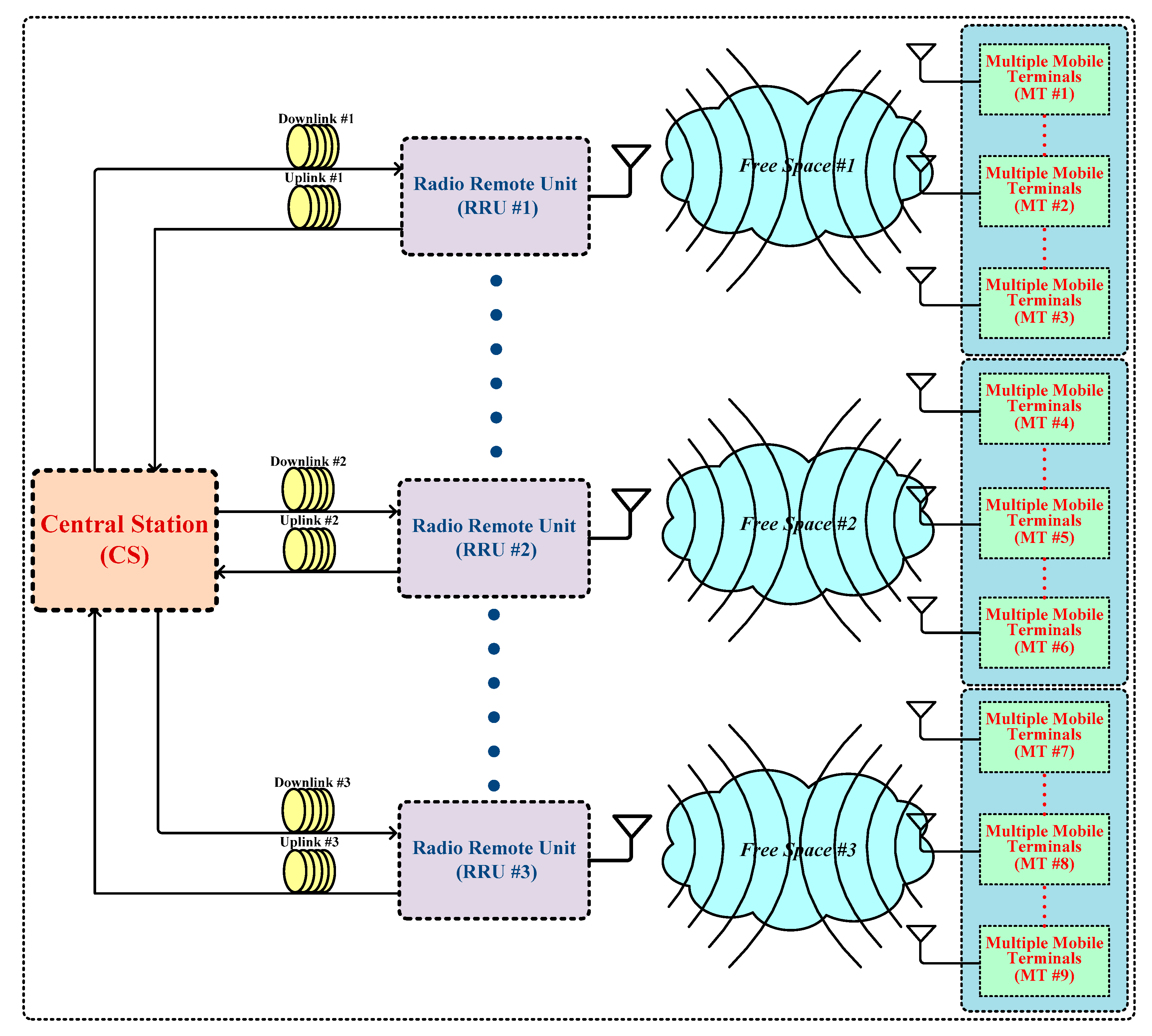
The setup of the RoF transmission system network with simultaneous wireless multi-mode operation based on the multi-wavelength optical comb, pulse sharping, and direct optoelectronic detection is shown in
Figure 1.
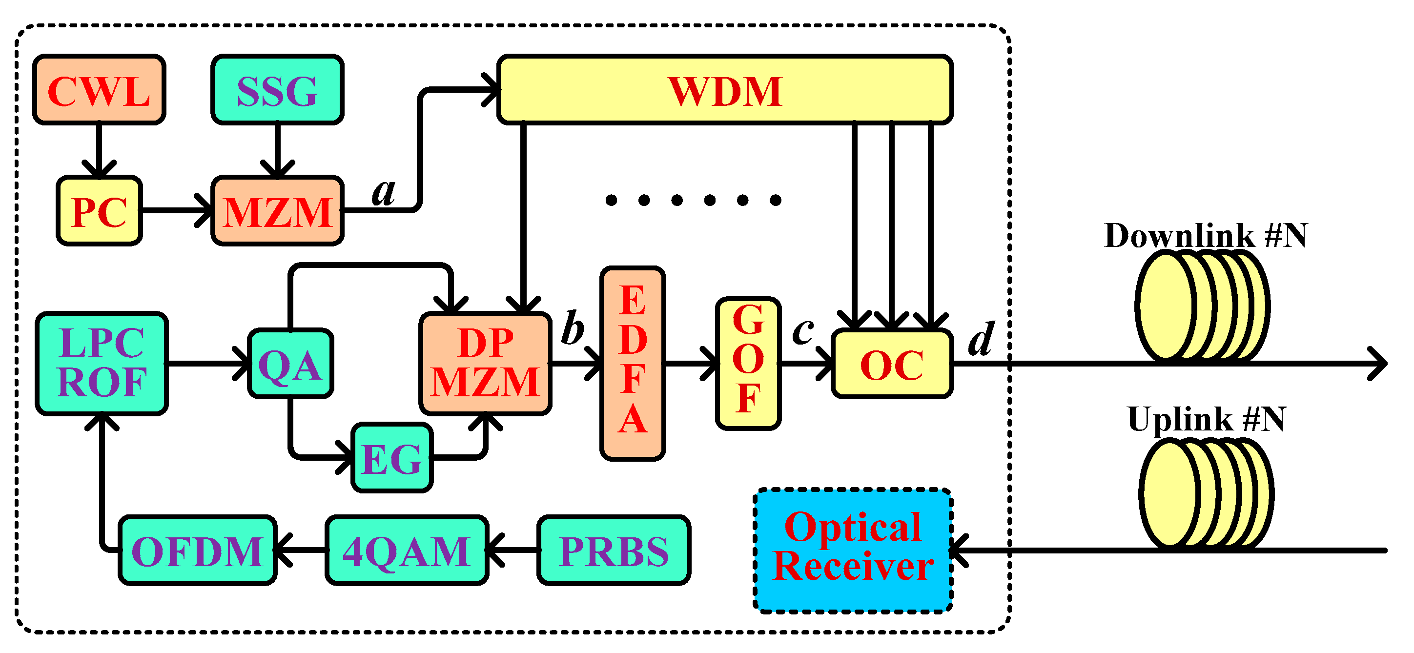
The RoF transmission system network with simultaneous wireless multi-mode operation contains one central station (CS), multiple radio remote units (RRUs), and multiple mobile terminals (MTs). The function block diagram of the CS can be seen in
Figure 2, and abbreviations for functional modules in the system diagrams can be seen below: CWL, continuous wave laser; PC, polarization controller; SSG, sine signal generator; MZM, Mach-Zehnder modulator; WDM, wavelength division multiplexing; DPMZM, dual port Mach-Zehnder modulator; EDFA, erbium-doped optical fiber amplifier; GOF, Gaussian optical filter; OC, optical combiner; PRBS, pseudo-random binary sequence; QAM, quadrature amplitude modulation; OFDM, orthogonal frequency division multiplexing; LPCROF, low pass cosine roll off frequency; QM, quadrature modulator; and EG, electrical gain.
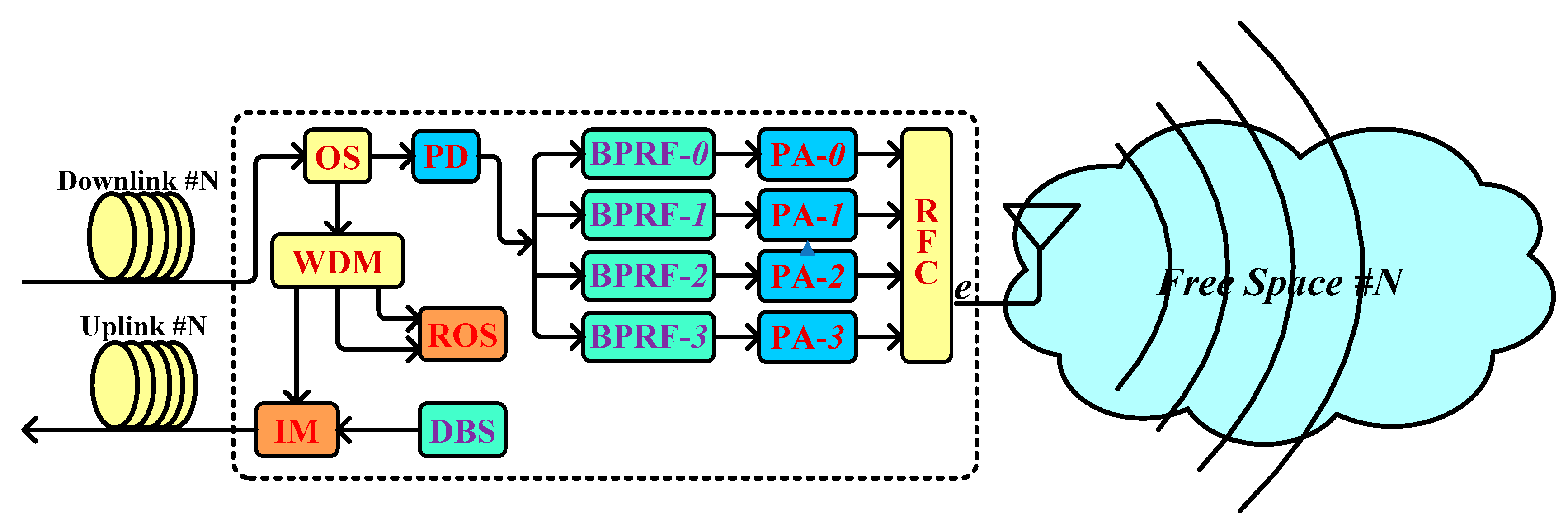
The function block diagram of the RRU can be seen in
Figure 3, and abbreviations for functional modules in the system diagrams can be seen below: OS, optical splitter; PD, photonic detector; BPRF, band pass rectangle optical filter; PA, power amplifier; RFC, radio frequency combiner; ROS, reserved optical source; DBS, digital baseband signal; and IM, intensity modulator.
These links between CS and RRUs are established through multiple pairs of the optical fiber downlink and the optical fiber uplink. These links not only can adopt multiple optical signals with the same wavelength split from one modulated optical carrier, but also can utilize multiple modulated optical carriers with different wavelength produced by multi-wavelength optical comb in the CS. The links between RRU and MTs are established by radio wave with the different RF bands, and the bands are produced by photo-electric detection via optical beat technique in the RRUs.
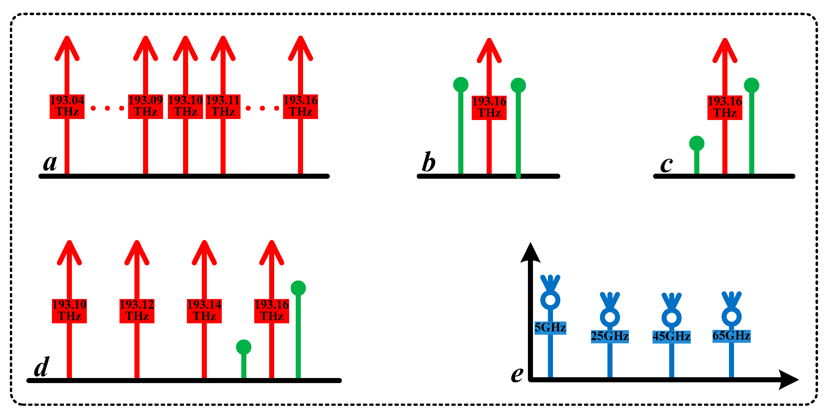
Consequently, the transport of radio signals in a centralized radio network center (i.e., CS) can be accomplished via the architecture of CS + RRUs + MTs. Using this approach, the schematic diagrams of spectra at the key points on the optical and microwave transmission links (i.e., ‘a’, ‘b’, ‘c’, ‘d’, and ‘e’, as shown in
Figure 2 and
Figure 3) are shown in
Figure 4.
The transmission rate is configured as 10 Gbps with the sequence length of 16384 and 32 simples per bit in the whole system. Continuous optical signals with the frequency of 193.1 THz, power of 15 dBm, and line-width of 10 MHz are emitted from the CWL. Sinusoidal signals with the frequency of 10 GHz are generated from the SSG. An optical signal is modulated by using a sinusoidal signal via the MZM with a symmetry factor of 0.85 and an extinction ratio (ER) of 30 dB. The bandwidth of the WDM is configured as 10 GHz. Multiple-channel optical signals can be obtained from the WDM.
An optical signal with a frequency of 193.16 THz output from the WDM is entered into the DPMZM with an extinction ratio of 30 dB, a switching bias voltage of 4 V, an insertion loss of 5 dB, a switching RF voltage of 4 V, a bias voltage-1 of 0 V, and a bias voltage-2 of 2 V. The optical signal is used as an optical carrier to carry 4QAM-OFDA signals. The PRBS with a bit rate of 10 Gbps, a sequence length of 32768, samples per bit of 32, and a symbol rate of 5 Gsps is employed. The QM with a frequency of 5 GHz is used for up-conversion. The gain of the EG is configured as –1.
The modulated signals output from the DPMZM are amplified by the EDFA with a gain of 20 dB and a noise figure of 4 dB. The amplified signals are filtered by the GOF with a frequency of 193.1625 THz and a bandwidth of 5 GHz. Then, the filtered signals and the three pure optical signals are filtered with frequencies of 193.14 THz, 193.12 THz, and 193.10 THz output from the WDM are coupled into a standard single mode fiber (SSMF) with a length of 50 km via the OC.
The BPRF-0 with a central frequency of 5 GHz, BPRF-1 with a central frequency of 25 GHz, BPRF-2 with a central frequency of 45 GHz, and BPRF-3 with a central frequency of 65 GHz are used for the wireless transmission of multiband mode. The gains of the PA-0, PA-1, PA-2, and PA-3 are all configured as 20 dB. Three optical sources with the frequency of 193.14 THz, 193.12 THz, and 193.10 THz are respectively obtained via the WDM in the RRU-1; one of the three sources is used for the uplink transmission with the length of 50 km, and the others are used as backup optical sources.
Therefore, multiple wireless communication links can be established between RRUs and MTs, which enables wireless microwave signals to be transmitted in the free space.
3. Multi-Wavelength Optical Comb
Multi-wavelength optical comb refers to optical spectra consisting of a series of uniform spaced frequency components with coherent and stable phase relations. With the rapid development of optical communication technology, multi-wavelength optical comb has been attracted more and more attention due to its wide application in the fields of optical arbitrary waveform generation, multi-wavelength ultra-short pulse generation and dense wavelength division multiplexing.
A multi-wavelength optical comb with the phase synchronization can be obtained by using RF-optics modulation and appropriate parameter configurations. The optical spectrum output from the MZM (i.e., point ‘a’) is the multi-wavelength optical comb that is shown in
Figure 2.
In
Figure 2, a continuous wave signal output from the CWL can be described as:
where
is the angle frequency of the optical field and
is the intensity of the optical field.
The MZM is an optical intensity modulator based on the optics interferometric principle, which consists of two 3 dB optical couplers. The mathematical model of the MZM can be described by:
where
is the phase difference between the two 3 dB optical couplers, which can be defined by:
where
; and
is the phase change, which can be defined as:
where
is the extinction ratio,
is the symmetry factor, and
is the modulation signal.
A sinusoidal signal output from the SSG can be described by:
where
is the amplitude, and
is the frequency.
In this paper, the extinction ration is configured as 30 dB, the symmetry factor is configured as 0.85,
is configured as 1, and
is configured as 10 GHz. From Equations (3)–(5), we can obtain:
From Equations (1), (2), (6), and (7), we can obtain:
where
.
Then, according to the Bessel function expansion method, the optical spectra output from the MZM can be obtained. The optical spectra are comprised of multiple optical sidebands with the frequency spacing of 10 GHz. These optical sidebands are distributed on both sides of .
From Equations (3), (4), (5), and (8), it can be seen that the amplitudes of the multiple optical sidebands are not only relevant to and the extinction ratio, but also relevant to the symmetry factor and the frequency of the sinusoidal signal. Consequently, when and the frequency of the sinusoidal signal are all constant, we can obtain multiple optical sidebands with appropriate amplitudes by adjusting the extinction and symmetry factor of the MZM. These optical sidebands not only have the same line-width but also have the synchronous phase.
In this paper, the amplitudes of multi-wavelength optical comb can be changed by adjusting the extinction and symmetry factor of the MZM. The optical spectra output from the MZM (i.e., multi-wavelength optical comb, the spectra of the point ‘a’ on the transmission link in
Figure 2) can be obtained by using the optical communication professional simulation software of OPTISYSTM and MATLAB. Then we can obtain a multi-wavelength optical comb with flat amplitudes by configuring the extinction as 30 dB and symmetry factor as 0.85. The multi-wavelength optical comb is shown in
Figure 5.
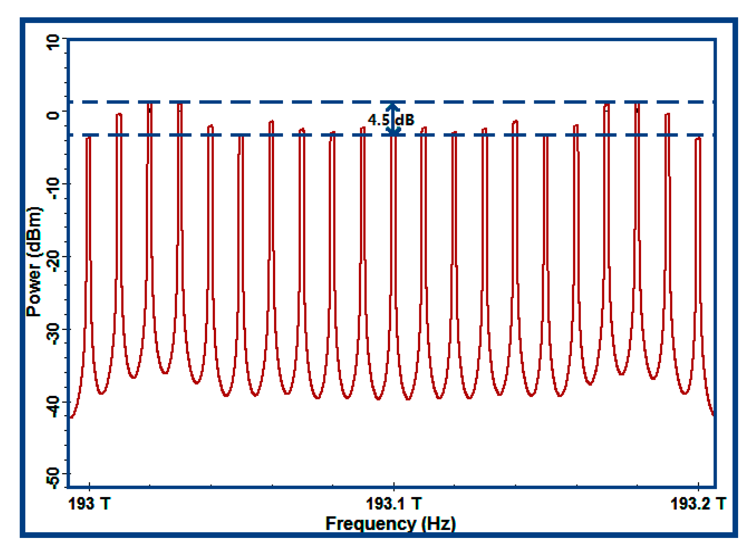
From
Figure 5, when the output of the multi-wavelength optical comb is 21 channels, we can notice that the intensity difference between the maximum and the minimum of these optical wavelengths was 4.5 dB. However, when the middle 13 wavelengths of the optical comb were taken, the intensity difference between the maximum and the minimum of these optical wavelengths would be reduced to 0.5 dB. Meanwhile, we could have a multi-wavelength optical comb with the best flatness, as shown in
Figure 6.
According to the needs for the frequency of an optical-millimeter wave signal, we can configure parameters to obtain the multi-wavelength optical comb with a suitable flatness.
In this paper, the multi-wavelength optical comb not only could provide multiple pure laser sources with the same line-width for downlink but also could supply them with the synchronous phase for the microwave photonic signal used to implement the transform of optics-RF directly via the PD. The scheme of multi-wavelength generation also supplied multiple laser optical sources for many remote RRUs (RRU-1, RRU-2, RRU-3, etc.) shown in
Figure 1. Consequently, the system architecture can be termed as fiber-RF remote (i.e., CS + RRUs).
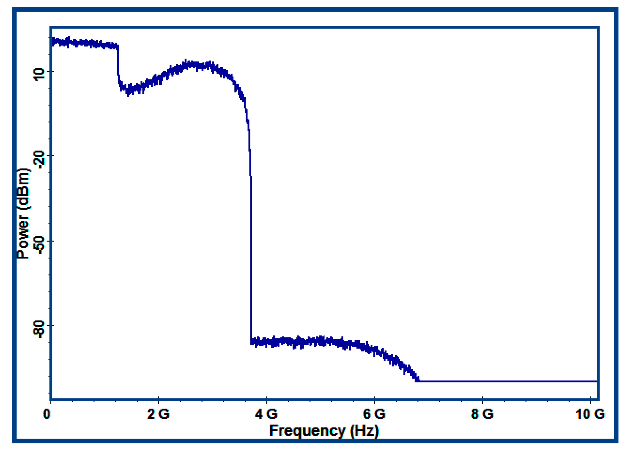
4. Results
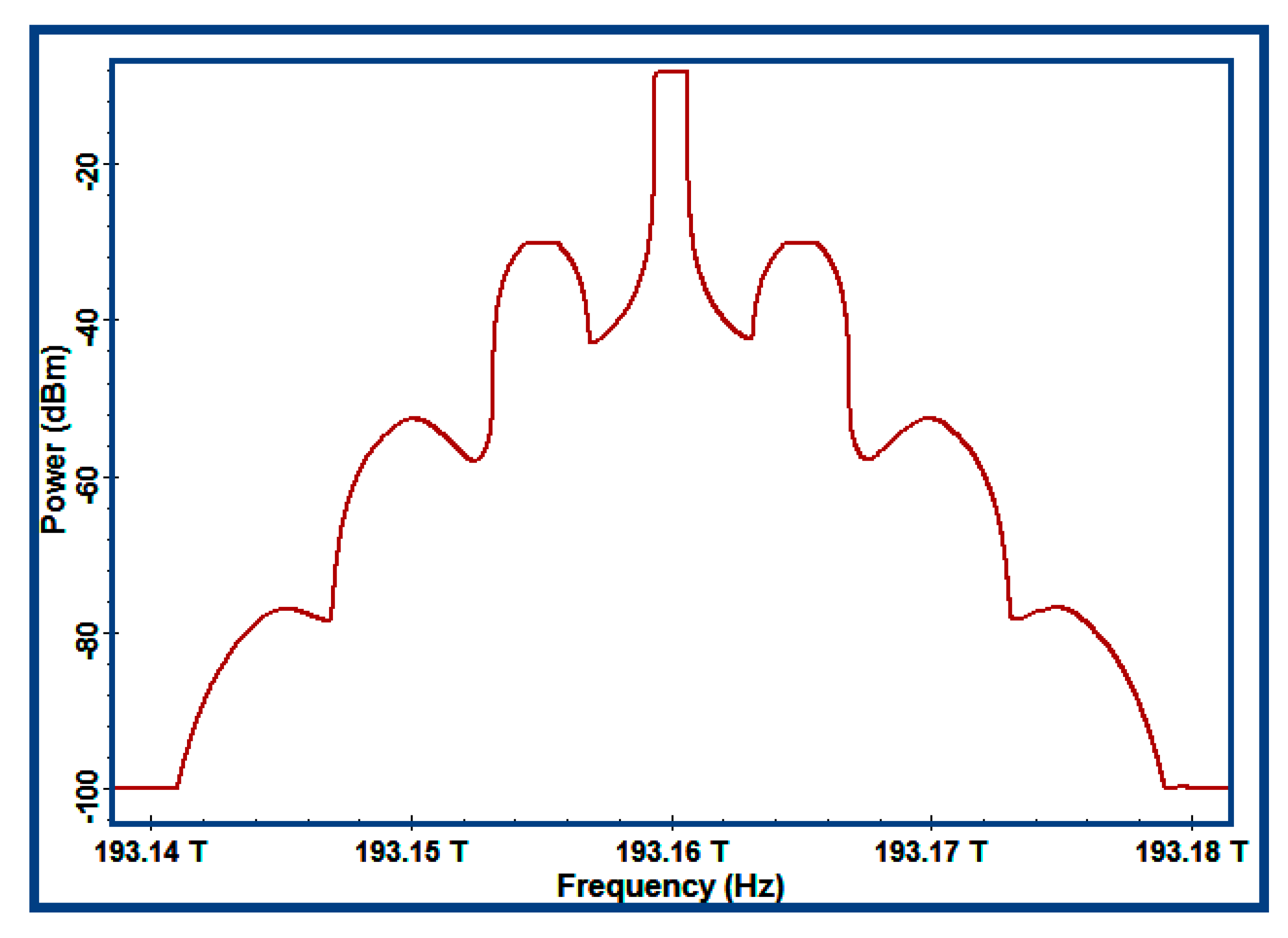
We could obtain the spectra output from the optoelectronic components by using the computer simulation. The output of the DPMZM (i.e., the optical spectrum of the point ‘b’ on the transmission link in
Figure 2.) is shown in
Figure 7, which also could be termed as the optical spectrum of the double-sideband modulated optical carrier.
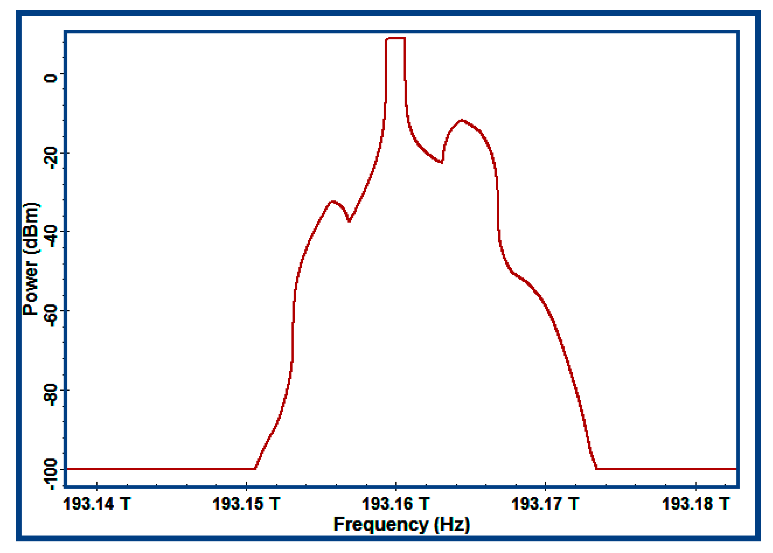
The output of the GOF (i.e., the optical spectrum of the point ‘c’ on the transmission link in
Figure 2) is shown in
Figure 8, which also could be termed as the optical spectrum of the single-sideband modulated optical carrier.
The single-sideband modulation format is not only good for decreasing the chromatic dispersion of the optical signals, but also cancelling the high PAPR of the OFDM signals [
23,
24]. In this paper, the single-sideband modulated optical signals have been obtained by the Gaussian optical filter, which is described by:
where
is transfer function of the GOF,
is the bandwidth,
is the insertion loss,
is the order of the filter,
is the center frequency, and
is the frequency of the signals. In this paper,
was configured as 5 GHz;
was configured as 1dB;
was configured as 1; and
was configured as 193.1625 THz. Consequently, Equation (9) can be described as:
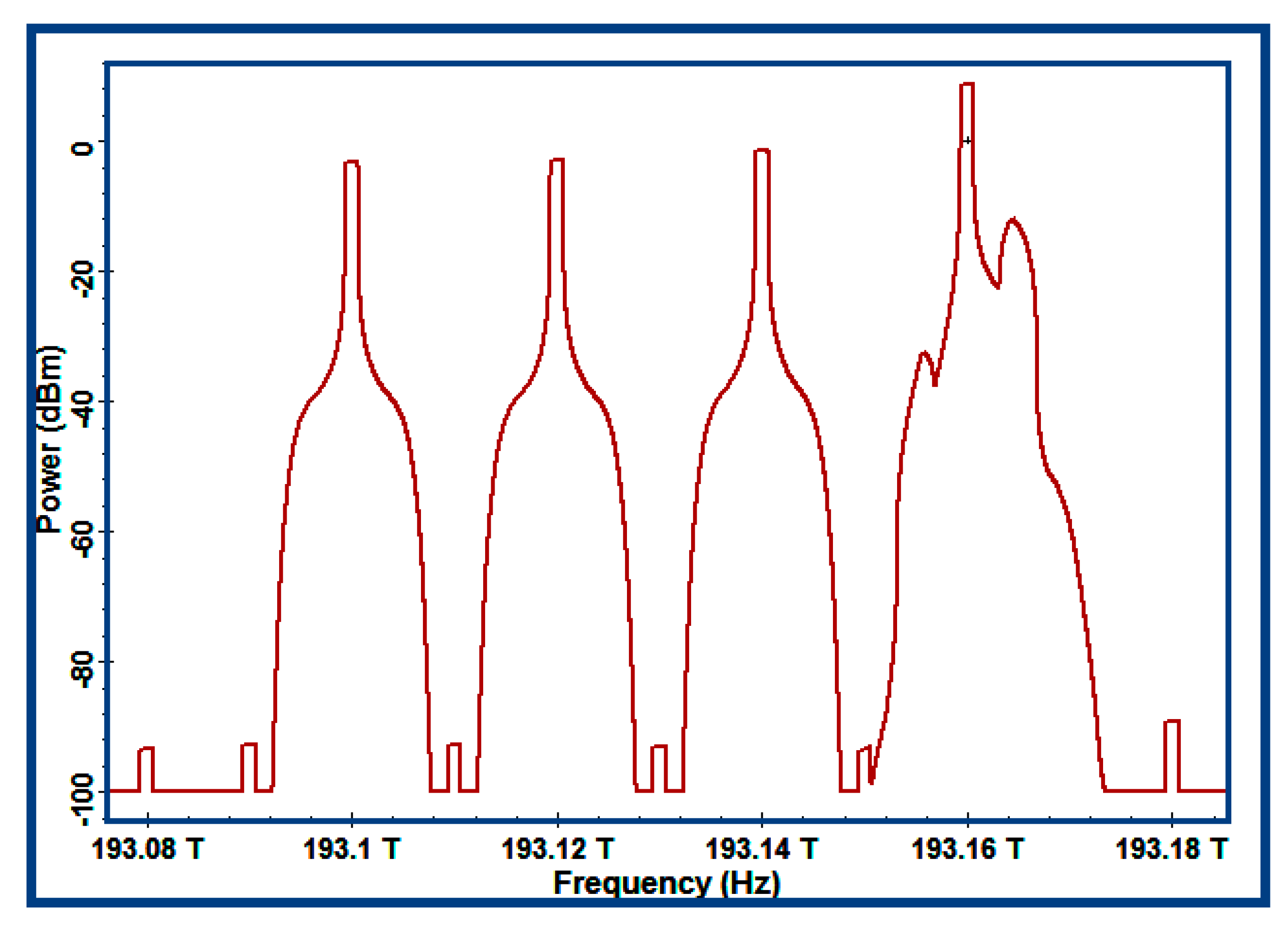
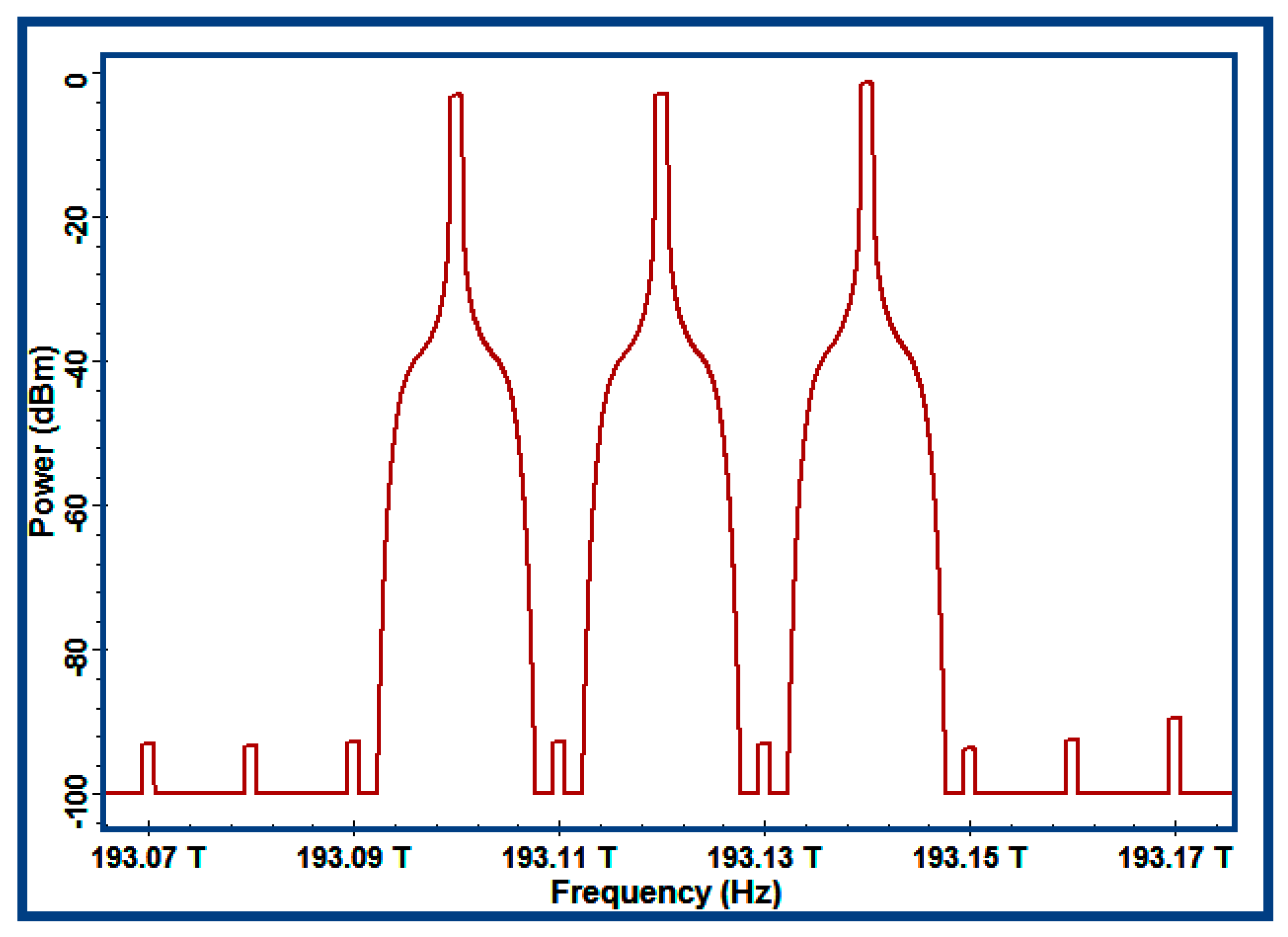
Three wavelengths with a central frequency of 193.14 THz, 193.12 THz, and 193.10 THz output from the WDM were combined with the filtered single-sideband optical signal via an optical coupler. Then, the optical spectrum output from the OC (i.e., the optical spectrum of the point ‘d’ on the transmission link in
Figure 2) could be obtained, as shown in
Figure 9.
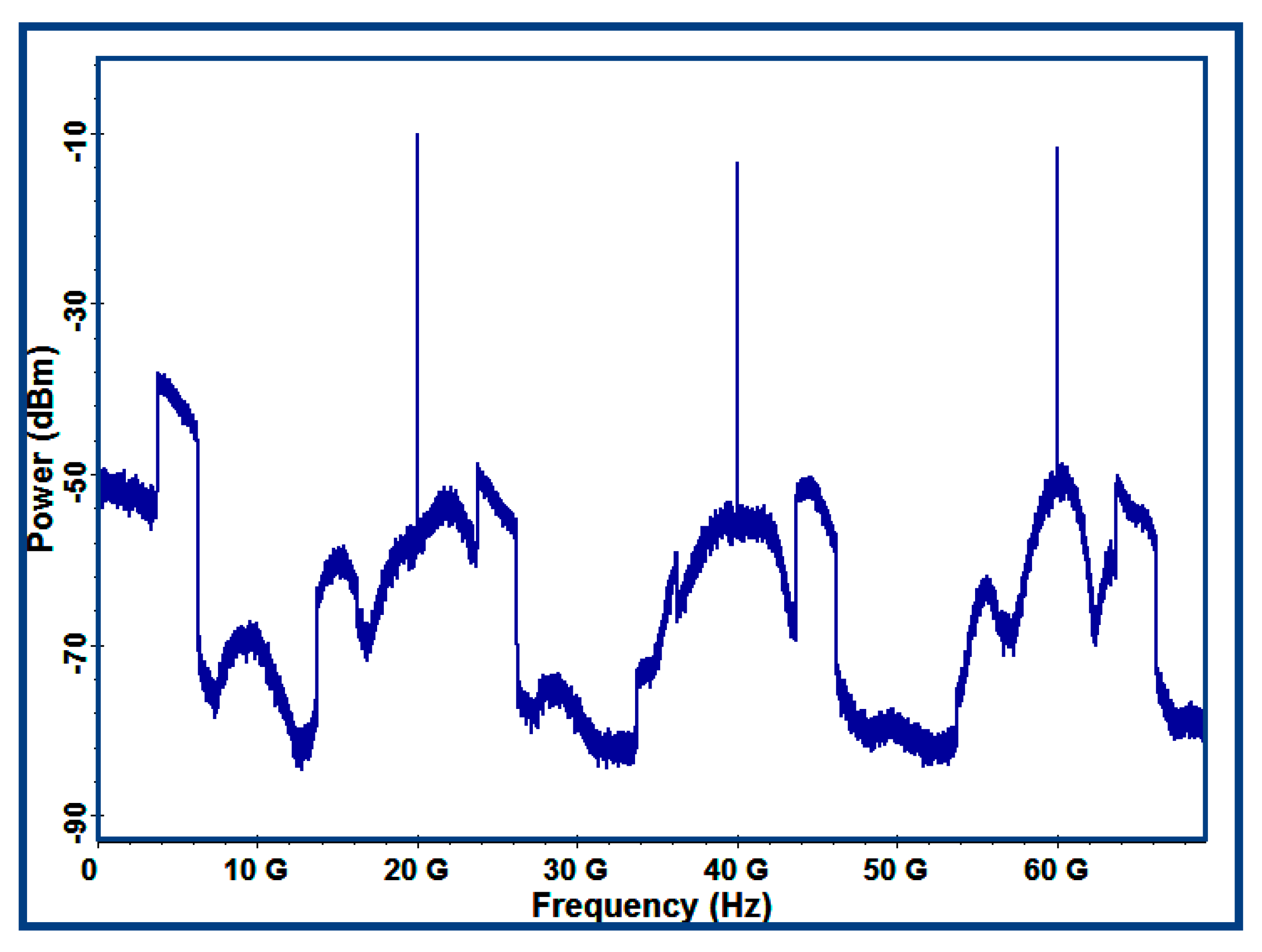
The optical signals transmitted from the CS were implemented photonics-RF transformation via the PD with the responsivity of 1 A/W in the RRU. By configuring the parameters, the suitable received power for the PD could be generated. Then, the RF signals could be obtained, the spectra of which are shown in
Figure 10.
The RF signals carry the same modulation information (i.e., 4QAM-OFDM signals) on the different carrier frequencies (i.e., 5 GHz, 25 GHz, 45 GHz, and 65 GHz). Consequently, this arrangement can supply wireless propagation with four carriers. That is to say, it realizes the optical wireless communications with the multiband mode. The 4QAM-OFDM signals can be demodulated from the four wireless carriers via the quadrature demodulators with different mixing frequency.
In RRU, three pure optical sources with the central frequency of 193.14 THz, 193.12 THz, and 193.10 THz could be obtained by using the OC and WDM, which are shown in
Figure 11. One of the tree optical wavelengths could be utilized for uplink communication, and the others were used as backup optical sources.
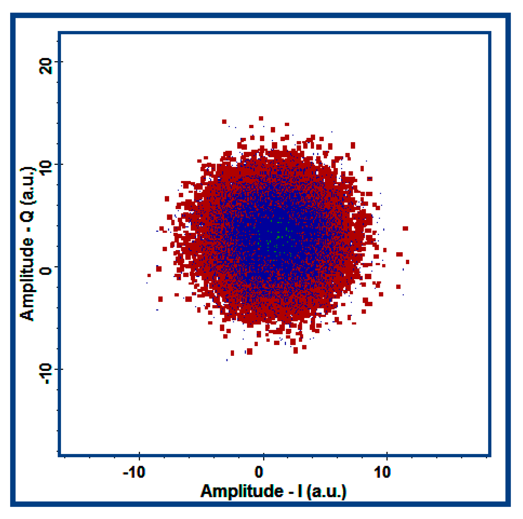
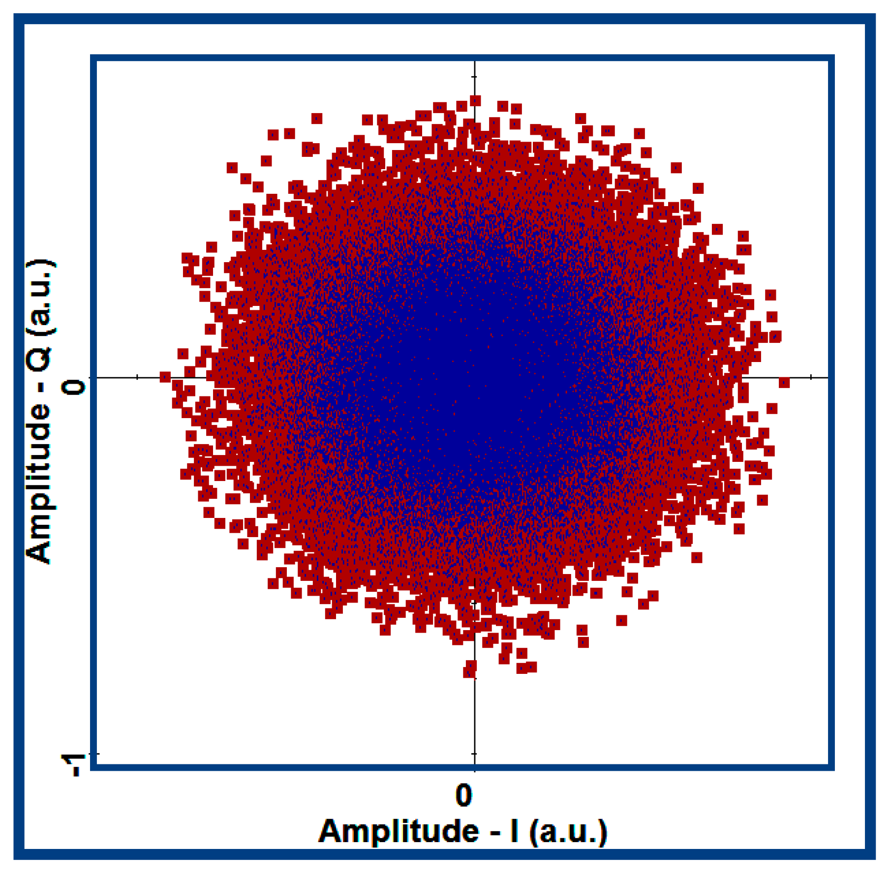
In the multi-waveband RF-OFDM receiver (i.e., MT in
Figure 1), the 4QAM-OFDM signals could be obtained via an electronic amplifier with a gain of 20 dB and a quadrature demodulator with a mixing of 5 GHz, 25 GHz, 45 GHz, and 65 GHz, respectively. In the MT, the quadrature demodulated 4QAM-OFDM signals were filtered by a duo-port low pass cosine-roll-off filter with a cut-off frequency of 3.1 GHz and a roll-off factor of 0.2; the spectrum of the filtered 4QAM-OFDM signal is shown in
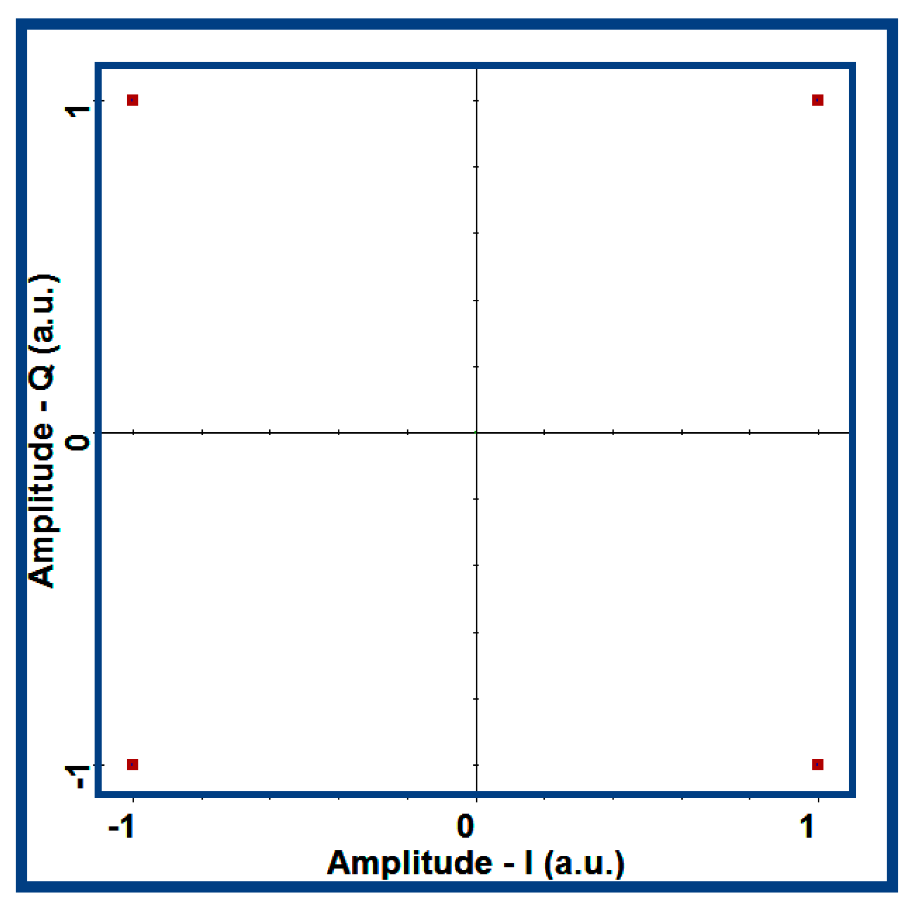
Figure 12; the constellation of the filtered 4QAM-OFDM signal is shown in
Figure 13. In the CS, the original constellations of the 4QAM signals and 4QAM-OFDM signals are shown in
Figure 14 and
Figure 15.
From
Figure 14 and
Figure 15, it can be seen that the original constellation of the 4QAM signals was very regular. The constellation became disorganized when 4QAM signals were processed by OFDM.
QAM employs two independent digital baseband signals to realize double-sideband amplitude modulation for two orthogonal co-frequency carriers. By utilizing the orthogonality of the spectrum of the modulated signal in the same bandwidth, two parallel channels of digital information transmission were realized. The modulation modes usually include binary QAM (4QAM), quaternary QAM (l6QAM), hexadecimal QAM (64QAM), ……, (the corresponding distribution map of spatial signal vector points is called constellation map), which have 4, 16, 64, ……, vector endpoints, respectively.
OFDM is a method of frequency division multiplexing, which is also a multi-carrier modulation technology. The principle of OFDM is to convert a group of high-speed serial data into multi-channel low-speed parallel data stream through series-parallel, and then modulate all low-speed signals to multiple orthogonal subcarriers for transmission. Low-speed parallel data can overcome the delay-spreading caused by multipath-effect due to its wide period time. Orthogonal aliasing of subcarriers in the spectrum makes full use of the spectrum resources. The orthogonal overlap of each subcarrier in the spectrum greatly improves the efficiency of spectrum utilization. Therefore, compared with single carrier modulation, OFDM technology can better meet the requirements of high-speed transmission in optical fiber communication.
From the concept of QAM above, it can be seen that constellation was based on a multiple binary (i.e., M-ary) digital sequence. The distribution map of spatial signal vector points composes the constellation. However, OFDM is a multi-carrier modulation technology; the series-parallel converted data are modulated onto the multiple RF carriers, and the modulated signals are not a digital sequence, which are different from the M-ary of QAM. Consequently, OFDM has not got the regular feature of the M-are constellation map, and the constellation of OFDM signals is disorganized. Of course, 4QAM signals are processed by OFDM, i.e., the constellation of 4QAM-OFDM signals is disorganized, which further validates
Figure 13 and
Figure 15.
5. Analysis
According to the arrangement, there are three pure optical sources and one modulated optical carrier that will be mixed using a PD. The spectrum of the four optical signals is shown in
Figure 9. The phases of the four light wave signals are synchronized, and they can be simplified as follows:
where
,
, and
are the pure optical sources;
is the modulated optical carrier;
,
,
, and
are the constants. Thus three new RF signals can be obtained by optical mixing between the three pure optical sources and the modulated optical carrier via the PD.
Consequently, according to the principle of the optical mixing [
31] and Equation (11), the RF electronic currents can be simplified as follows:
where
is a frequency of the QM, the value of which is configured as 5 GHz; the equations (
), (
), and (
) are the central frequencies of the RF signals. From the configuration parameters of the system, the frequencies of the four optical signals were 193.10 THz, 193.12 THz, 193.14 THz, and 193.16 THz, respectively. Consequently, from Equation (12), the central frequencies of the three RF signals and the frequency of the QM (i.e.,
) can be described as follows:
According to the theoretical analysis and deduction, the wireless carriers with the central frequencies of 5 GHz, 25 GHz, 45 GHz, and 65 GHz can be obtained via optics-RF transform, which is also verified by the simulation results as shown in
Figure 10.
Consequently, we could get the others wireless carriers with the central frequency of the odd multiple of 5 GHz (i.e., 10n + 5 GHz, where n can be 1, 2, 3, 4, 5, 6, and 7) via selecting suitable wavelengths from the multi-wavelength optical comb.
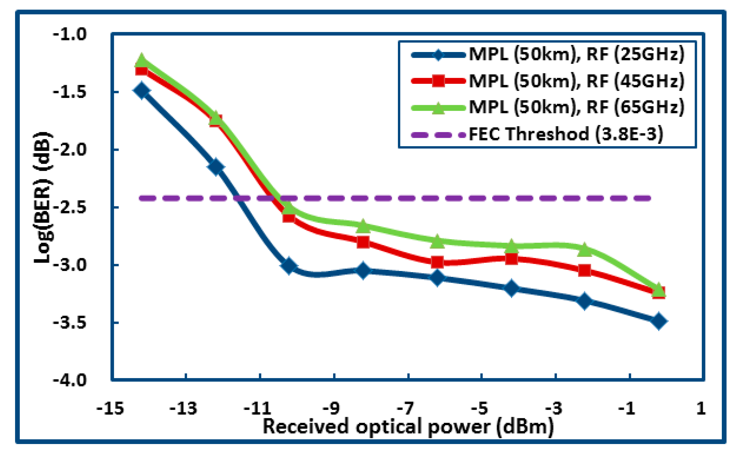
The bit error rate (BER) of the MPL and the BER of the wireless communication between the RRU and the MT are the key performance indicators (KPI) of the system. In the downlink (i.e., the MPL with 50 km), when the transmission rate is configured as 10 Gbps, the relationships between the received optical power (ROP) and the BER could be obtained, as shown in
Figure 16.
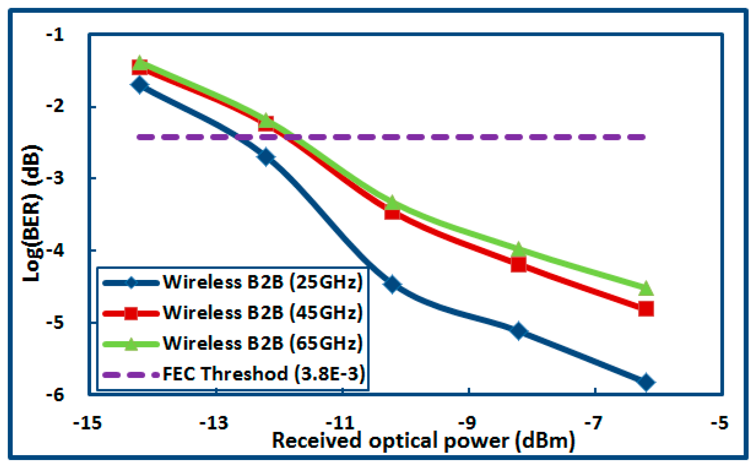
In the wireless link (i.e., the link between the RRU and MT), the relationships between the ROP and the BER could be obtained, as shown in
Figure 17.
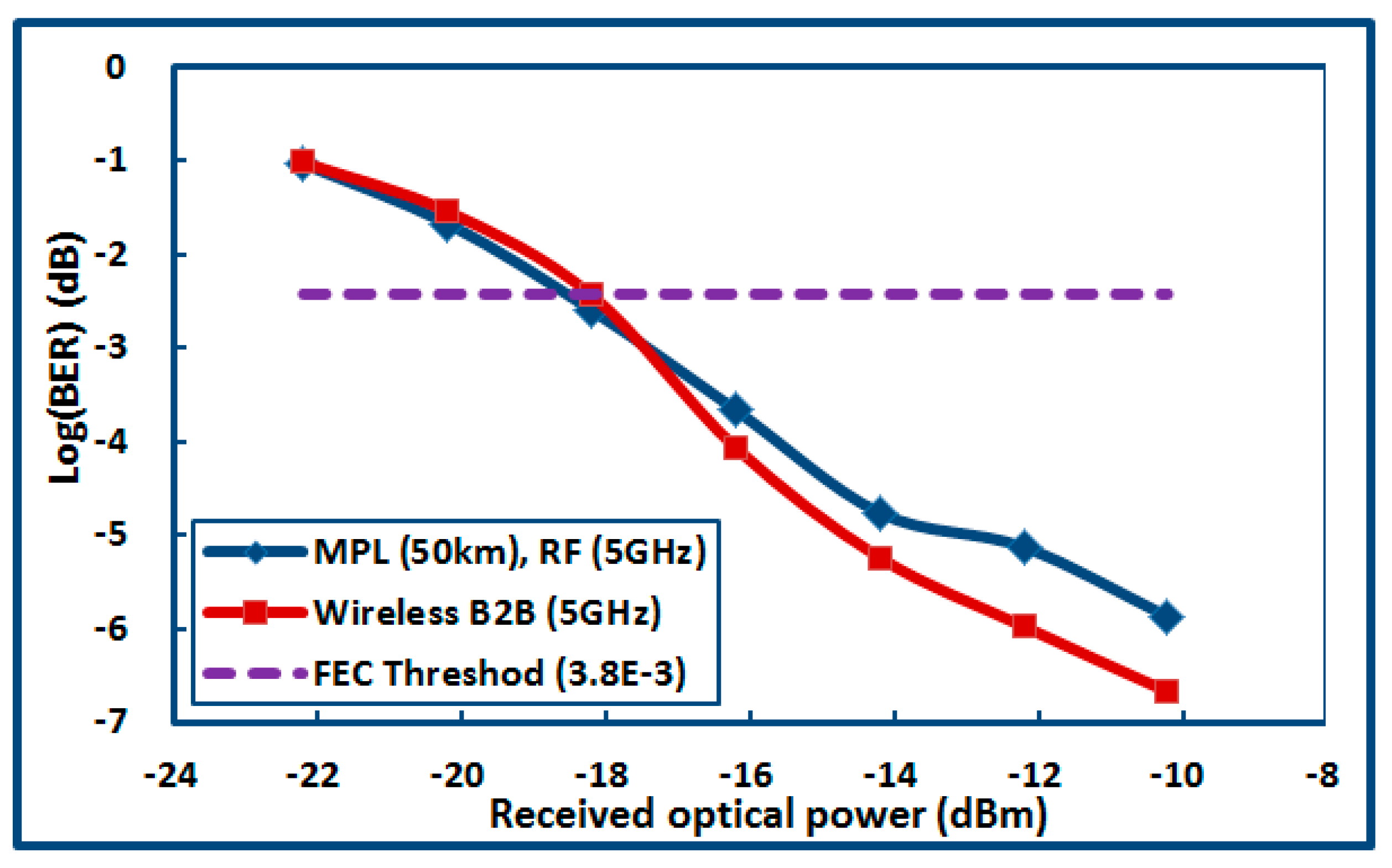
In the downlink and wireless link, the central frequency of RF carrier signals was 5 GHz, and the relationships between the BER and the ROP could be obtained, which are shown in
Figure 18.
From
Figure 16,
Figure 17, and
Figure 18, we could obtain that: First, the KPI below the forward error correction (FEC) threshold of 3.8 × 10
−3 could be accepted; second, the transmission performances of the RF carriers with the central frequency of 25 GHz, 45 GHz, and 65 GHz have little difference in the MPL with 50 km, the obvious difference of which is about 1 dB in the wireless link, and it shows that the RF carrier with the central frequency of 25 GHz has a better wireless transmission performance; third, the RF carrier with the central frequency of 5 GHz has the best transmission performance; fourth, a good transmission performance can be improved by increasing the ROP in the RRUs.
6. Discussions
In the area of optical communications, it is commonsense that the sophisticated optical coherent receivers need more construction costs and maintenance costs than the optoelectronic receiver although which has more advantages in term of optical signal-to-noise rate (OSNR) performance and long distance transmission. Due to one RRU needing one optical receiver, it is especially true in RoF communication systems with multiple remote units. Consequently, direct optoelectronic demodulation should be as the first choice when the transmission rate and OSNR are acceptable. In fact, the ROF system for wireless access only needs signal coverage in areas with a radius of tens of kilometers. In addition, when the optical transmission rate used for single carrier wireless access in a RoF system reaches 20 Gbps, which is far more than the current 5G standard requirement. The optical transceiver with a speed of 20 Gbps employed direct modulation and demodulation has better advantages, such as low price and mature technology.
Consequently, in this paper, a strict phase synchronized laser is not required as a local oscillator in the RRU to demodulate the coherent optical carrier signal. Compared with the receiving unit of the traditional coherent RoF system [
27,
32,
33,
34], the cost of the receiver and the difficulty of periodic maintenance are greatly reduced due to the absence of the local oscillator, especially in the distribution of multiple remote unit networks.
In this paper, the optical comb could provide multi-wavelengths with phase synchronization. These optical wavelengths could be used to generate tunable millimeter waves employing optical heterodyne technique. Meanwhile, those multi-wavelengths without being modulated could be transmitted into radio remote units (RRUs) via WDM. These pure optical signals could be employed for the uplinks. Compared with those traditional system solutions of RoF or MPL [
24,
25,
26], there were more tunable optical wavelengths with flat amplitude that could be employed. In this arrangement, more tunable millimeter waves could be obtained by optical heterodyne technique via configuring the center frequency of the SSG.
Moreover, in this paper, compared with the RoF system based on a tunable multi-wavelength optical comb produced by recirculation loop [
23], uplink without EDFA reduced the construction cost and maintenance complexity of RRUs greatly.
From the RoF system performances, it could be seen that the optical transmission performance of the MPL was very good when the ROP was greater than –10 dBm in
Figure 16; and a good wireless transmission performance could be obtained when the ROP was larger than–12 dBm in
Figure 17. However, the MPLs with the frequency of 5 GHz, 25 GHz, and 45 GHz should be recommended due to the better receiving sensitivity. Moreover, from
Figure 17 and
Figure 18, it can be seen that the wireless links with the frequency of 5 GHz and 25 GHz had better application expectation.
7. Conclusions
In this paper, the innovations of this study could be summarized as follows:
It was an initial attempt to accomplish simultaneous wireless multi-mode operation on a single optical carrier.
In order to achieve the RoF system with simultaneous wireless multi-mode operation, multi-wavelength optical comb with 13 flat optical wavelengths and a wavelength space of 10 GHz were proposed innovatively. These wavelengths not only could be used as multiple downlinks to transmit the optical signals from the CS to the RRUs, but also could be utilized as the optical sources for multiple uplinks.
In order to improve the spectral efficiency and reduce the chromatic dispersion transmission, we proposed the 4QAM-OFDM signal with single-sideband, which is based on optics pulse shaping.
Compared with sophisticated multiple mixing in the electric domain, the generation of RF signals with ultra-high frequency and multiband mode employed optics mixing technology based on the optical domain was a good choice.
Compared with the optical coherent detection, photoelectric direct detection of 4QAM-OFDM optical signals was a low and sample method of demodulation. Moreover, because of the centralized management of active optical modules (that is to say, there is no independent active optical module in RRUs), the construction cost and maintenance difficulty of RRUs were greatly reduced.
Moreover, from the list of bands that 3GPP had designated for the 5G NR, we noticed that the 5G had considered the coexistence scheme of the microwave and millimeter wave used for wireless propagation. Therefore, flexible wireless carrier switching between the microwave and millimeter wave could be realized immediately.
Consequently, in this paper, the scheme of the simultaneous wireless multi-mode operation was a good selection for future mobile communications. The system architecture of CS + RRUs is based on the multi-wavelength optical comb and direct optoelectronic detection is a valuable scheme for the future wireless networks with low cost, low complexity, and being maintenance friendly. The format of the 4QAM-OFDM signals with pulse sharping is good for the transmission in the MPLs.

