1. Introduction
Microwave bandpass filters (BPF) are key building elements of communication systems. They should meet several requirements, mainly system performance frequency response, reduced size, and manufacturing cost. Nowadays, research in the microwave domain is focused on BPF size miniaturization and integration.
Recently, it has become desirable to develop new types of microstrip bandpass filters with small size and planar fabrication. Parallel coupled microstrip bandpass filters are common elements in many microwave systems [
1], due to their many advantages such as planar design, easy analysis, and low cost. One type of miniaturized microstrip bandpass filter that uses a pseudo-interdigital structure without ground holes ground is proposed in [
1] and a variety of resonator types have been introduced, including split-ring resonators [
2] or stepped impedance resonators (SIR) [
3] to achieve bandpass filter frequency responses.
On the other hand, wearable technology has been widely developed and deeply studied in recent years. It has been adopted in many applications including on-body networks [
4], location tracking [
5], fitness monitoring [
6], and e-textile metamaterial signal propagation control [
7]. The common features of e-textile systems are a low-profile, lightweight, wireless connection and multifunctionality, which are required by modern wearable applications.
In this paper, we present for the first time an e-textile microwave filter based on an embroidered meander microstrip line. The new microstrip filter structure has advantages in terms of compressibility, stretchability, and high durability to repetitive deformations. Although the obtained performance of the proposed filter was lower than what was obtained by means of conventional PCBs, the measured results demonstrated the functionality of the proposed filter and that it can be used as an alternative to a PCB substrate when a flexible substrate is a design requirement.
The main novelty of the paper consists of utilizing a textile material as substrate to develop a meander filter at the microwave frequency band. In comparison with conventional devices, the proposed filter has the ability of controllable electromagnetic properties and device flexibility. Furthermore, the proposed filter guarantees a bandpass from 7.17 to 8 GHz with a return loss lower than −30 dB.
The e-textile filter was simulated, fabricated, and measured in the bandwidth delimited by 7.17–8 GHz with a centre frequency of 7.58 GHz.
The remainder of the paper is organized as follows.
Section 2 describes the theoretical framework of the proposed wearable meander microwave filter. In
Section 3 the filter implementation and experimental results are shown and discussed. In
Section 4 the bending effects on the filter performance are analysed experimentally. Finally, in
Section 5 the conclusions of this work are summarized.
2. Theoretical Framework
The proposed bandpass filter (BPF) was designed on an e-textile felt substrate with characterized h = 1 mm thickness, dielectric constant εr = 1.2, and loss tangent tan δ = 0.0013. In order to determine the substrate dielectric constant and loss tangent of the felt substrate, the resonance method based on a split post dielectric resonator (SPDR) measurement was carried out.
The filter was designed using a quarter wavelength (λ/4) microstrip with different characteristic impedance of the line to achieve stepped impedance.
Since most filters are composed of linear components based on simple and fast computer-aided network analyses, let us first consider the stepped impedance resonator (SIR) concept. SIR allowed to establishing a relation between the linear elements equivalent circuit model and the layout of the physical dimensions.
A microstrip stepped impedance resonator is formed by joining two transmission lines with different characteristic impedances,
Z1 and
Z2, with the corresponding electrical length θ
1 and θ
2, respectively [
8], as shown in
Figure 1. The resonant condition of the SIR depends on the values of θ
1, θ
2 and R. Furthermore, the analytical models are used to compute the circuit parameters at 7.58 GHz central frequency. The total electrical length of the structural fundamental is given by [
9], which is
. The resonance condition of an SIR will occur when
where
K is the impedance ratio. For this design we considered
K = 0.4. The characteristic impedance of lines are designed at
Z1 = 50 Ω,
Z2 = 121 Ω and the electrical lengths of a line are θ
1 = 31°, θ
2 = 79°.
The typical structure of the SIR as shown in
Figure 1 can be mathematically verified by solving this electrical network using circuit theory. The overall ABCD parameters of this circuit were calculated by calculating the ABCD parameters of the individual line steps. The ABCD parameters of the circuit can be determined by [
10], as follows:
where A, B, C, and D are the network parameters of the transmission matrix, which is the result of the multiplication of the three ABCD matrices corresponding to the network in
Figure 1.
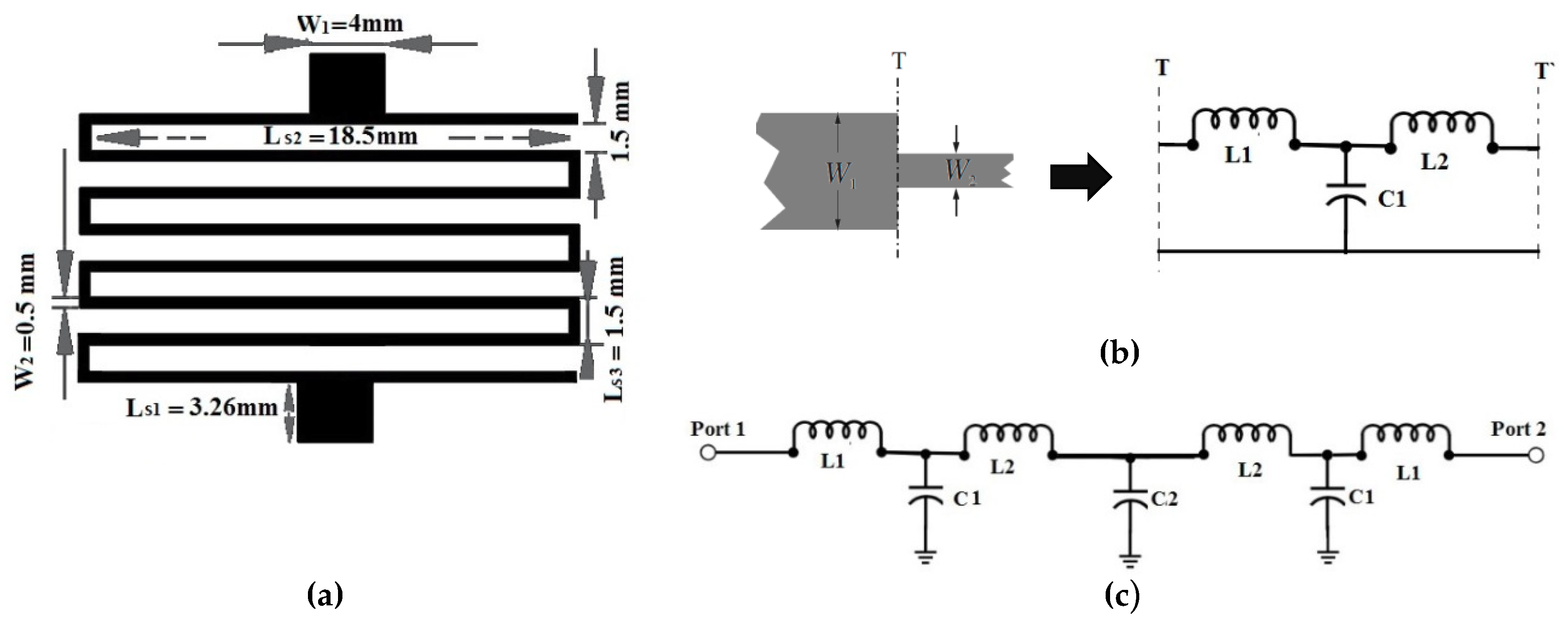
In order to reduce the filter size, in the next step the meandered line SIR was considered. The layout of the proposed filter is illustrated in
Figure 2a, where the line width for microstrip was set as
W1 = 4 mm, which causes characteristic impedance
Z0 = 50 Ω on the substrate. The detailed dimensions were as follows:
Ls1 = 3.26 mm,
Ls2 = 18.5 mm,
Ls3 = 1.5 mm, and the spacing between two meander lines S = 1.5 mm. The width for microstrip quarter-wavelength resonators was set as
W2 = 0.5 mm.
The equivalent circuit model of a filter helps us to understand the behaviour of the design. As illustrated in
Figure 2b, the subnetwork can be represented by an L-C circuit and the values of
L and
C of the individual steps were calculated by the use of the standard equations in [
8]. For the symmetrical microstrip steps, the subnetworks were described by the capacitance (
C1) and inductances (
L1,
L2) corresponding to the equivalent circuit shown in
Figure 2b. On the other hand, the proposed meander microstrip lines act as a resonant (
L2C2) circuit. The vertical elements act as the inductor and horizontal elements act as the capacitor. The overall electrical equivalent circuit of the proposed filter structure, which is shown in
Figure 2c, can be obtained by combining the equivalent circuits of symmetrical steps and meander microstrip lines. This circuit was simulated using an Advanced Design System (ADS) simulator and its frequency response was compared with full 3D electromagnetic CST (Computer Simulation Technology) Microwave Studio 2018 software.
The capacitance and inductances of the equivalent circuit indicated in
Figure 2c can be approximated using the following formulation [
8].
The estimation of the capacitance of the interdigital layout can be given by
The total length is given by
where N is the number of turns, and S is the spacing between two meander lines. The inductance per unit length is calculated as follows [
8]:
where
for
i = 1, 2 are the inductances per unit length, having widths
W1 and
W2, respectively.
and
denote the characteristic impedance and effective dielectric constant corresponding to width
Wi and c is the light velocity in free space.
The values of the different parameters can be initially estimated from the physical dimensions, but it will finally be necessary to optimize them by a tuning procedure to fit the measured response.
3. Filter Implementation and Results
The fabric structure was a non-woven structure with a 100% polyester composition. These textile substrates are resistant to sweat and humidity and they offer some key advantages, including durability, chemical moisture resistance, and heat stability. The weight was 211 g/m2, and the technique used was double-sided needle punching.
The selected conductor yarn corresponds to a commercial Plated Nylon 66 Yarn 117/17 dtex 2-ply (Shieldex, Bremen, Germany) and is composed of 99% pure silver-plated nylon yarn 140/17 dtex with a linear resistance < 30 Ω/cm. The used stitch type corresponds to the ISO 4915:1991 301 standard.
The conductive thread was relatively thick compared to conventional embroidery thread, due to the mechanical restrictions of the embroidery machine. In order to optimize the fabrication process, the conductive thread was used in the bobbin of the embroidery machine, whereas a conventional embroidery yarn was considered for the upper thread. A certain degree of tension control in the upper thread was maintained in order to increase the accuracy of the stitching geometries and patterns. The stitch spacing corresponds to the distance between two needle penetrations on the same side of a column. The homogeneous layout was converted to a stitch pattern using the Digitizer Ex software for fabrication process. This software package is used to create the stitch pattern, which is then exported to the embroidery machine and stitched. A Singer Futura XL-550 embroidery machine (Singer Corporation, La Vergne, TN, USA) was used to manufacture the prototype.
The proposed design was embroidered with a satin pattern with 60% density. The density determined the gap between stitches. For narrow columns, the stitches were tight, thus requiring fewer stitches to cover the fabric. In areas with very narrow columns, less dense stitches were required because too many needle penetrations can damage the textile sample. Thus increasing the embroidering density boosted surface conductivity.
A homogeneous, uniform, commercial WE-CF adhesive copper-sheet layer (constant thickness t = 35 µm) was chosen as the ground plane.
Figure 3 shows a photograph of the BPF embroidered wearable prototype. The idea was to use e-textiles to enable low embroidery tension and high flexibility, improving the embroidery process. The fabricated filter satisfied the requirements of providing the wearer with a compact size, flexible materials, ease of washing, and a very attractive wearable application.
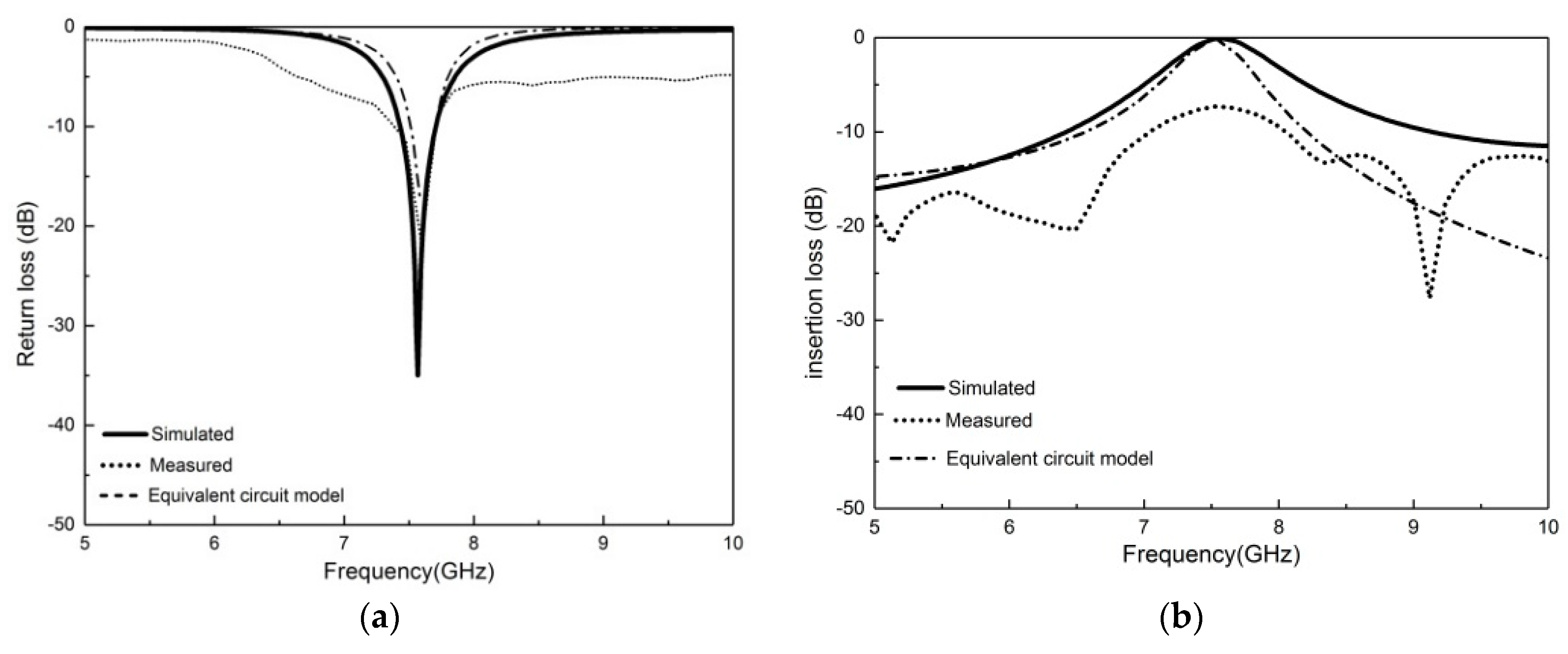
Figure 4 shows a comparison between the simulated and measured frequency responses of insertion losses (S
21) and return losses (S
11). The S
21 and S
11 were tested up to 10 GHz by means of a microwave analyser, N9916A FieldFox (Keysight, Santa Rosa, CA, USA), operating as a vector network analyser.
As illustrated in
Figure 4a,b, the bandwidth of the simulated and equivalent circuit model results was between 7.17 GHz and 8 GHz. Furthermore, there was a clear relationship between the equivalent circuit model and the layout of the physical dimensions.
The simulated and equivalent circuit model of the proposed circuit presented good electrical performance, with an insertion loss of −0.5 dB and a return loss of −30 dB at the frequency (7.58 GHz), whereas the measured insertion loss and the return loss were about −8 dB and −29 dB, respectively. The discrepancy between the simulated and measured results was due to fabrication tolerances, the thickness of the adhesive that was used for the ground layer, and improper soldering of the connector as well as the lack of homogeneity of the embroidery, in comparison with standard PCB metallization. Nevertheless, the bandpass behaviour was clearly defined and could be boosted by a conventional amplification technique.
The equivalent circuit parameters were extracted from the optimization of the circuit to fit the simulated and measured response.
Table 1 shows a summary of the parameters corresponding to the capacitance and inductance parameters of
Figure 2c, for the best fit we were able to find from the simulation and theoretical point of view.
4. Bending Effects
In wearable systems it is very difficult to keep the substrate in a flat configuration all the time, especially when the prototype is made of textile materials and is frequently bent due to human body morphology and movements. Therefore, it is necessary to investigate the prototype performance characteristics under bending conditions.
Figure 5 shows the output characteristics of the proposed BPF under bending conditions.
It is observed that by changing the bending radius to 40 mm, the resonant frequency was shifted up 4.25 MHz/mm
5. Conclusions
A compact e-textile bandpass filter was designed and successfully fabricated and tested. The proposed design was a fully embroidered conductive thread meander microstrip on a textile substrate. Significant agreement was achieved for the electromagnetic (EM) layout simulations, equivalent circuit model, and the experimental results. The measurement results exhibited a well-defined bandpass at a centre frequency of 7.58 GHz, with a return loss of −29 dB and −8 dB for the insertion loss while, the simulated return loss response was −35 dB and the insertion loss was −0.5 dB. The proposed filter has the advantages of miniature size, flexibility, durability, ease of washing, and is also suitable for applications in health management based on signal monitoring and sports.


