Article

Charuco Board-Based Omnidirectional Camera Calibration Method

1
Department of Electronic Engineering, Sogang University, Seoul 04107, Korea
2
Electronics and Telecommunications Research Institute, Daejeon 34129, Korea
*
Author to whom correspondence should be addressed.
Electronics 2018, 7(12), 421; https://doi.org/10.3390/electronics7120421
Submission received: 8 November 2018 / Revised: 30 November 2018 / Accepted: 6 December 2018 / Published: 11 December 2018
(This article belongs to the Section Circuit and Signal Processing)

Abstract

:
In this paper, we propose a Charuco board-based omnidirectional camera calibration method to solve the problem of conventional methods requiring overly complicated calibration procedures. Specifically, the proposed method can easily and precisely provide two-dimensional and three-dimensional coordinates of patterned feature points by arranging the omnidirectional camera in the Charuco board-based cube structure. Then, using the coordinate information of the feature points, an intrinsic calibration of each camera constituting the omnidirectional camera can be performed by estimating the perspective projection matrix. Furthermore, without an additional calibration structure, an extrinsic calibration of each camera can be performed, even though only part of the calibration structure is included in the captured image. Compared to conventional methods, the proposed method exhibits increased reliability, because it does not require additional adjustments to the mirror angle or the positions of several pattern boards. Moreover, the proposed method calibrates independently, regardless of the number of cameras comprising the omnidirectional camera or the camera rig structure. In the experimental results, for the intrinsic parameters, the proposed method yielded an average reprojection error of 0.37 pixels, which was better than that of conventional methods. For the extrinsic parameters, the proposed method had a mean absolute error of 0.90° for rotation displacement and a mean absolute error of 1.32 mm for translation displacement.

1. Introduction

Recently, with the development of head-mounted displays, it has become possible to provide users with immersive virtual reality (VR). In addition to computer graphics, capturing a real scene with a camera and transferring it to a VR space has become imperative to providing VR content. Moreover, to further increase the user’s degree of freedom (DoF) and immersion in the VR space, various omnidirectional cameras, such as a dioptric camera [1], catadioptric camera [2,3,4,5], and polydioptric camera [6,7,8,9], have been proposed. In this paper, we deal with the polydioptric camera such as Facebook Surround 360 [10], Google Jump [11], Richo Theta [12], and Samsung Gear 360 [13]. These omnidirectional cameras are divergent structures and capture surrounding image information simultaneously through overlapping the images from multiple cameras. To create real-world quality VR content, since we need to extract the depth information instead of simply stitching the images, we have to understand the internal characteristics and the geometric positions of the installed cameras.
For this purpose, two essential calibrations [14] must be performed. First, there is an intrinsic calibration for measuring the sensor characteristic and lens distortion between cameras constituting the omnidirectional camera. Then, there is an extrinsic calibration for measuring the relative three-dimensional (3D) positional difference (rotation and translation) among the cameras. Generally, to find these calibrated parameters for a single camera, conventional methods artificially provide planar feature points such as a chessboard. However, when applying these conventional calibration methods to the omnidirectional calibration method, it is difficult for the cameras to share the same 3D world coordinate system and the same method has to be repeated several times for each camera.
Whereas, a self-calibration is also well-studied after Duane [15] and Kenefick et al. [16] proposed a bundle adjustment concept for lens distortion [17,18,19]. The self-calibration can estimate the intrinsic parameters and the relative position from relative orientation through the bundle adjustment of correspondence pairs extracted from captured multi-view images [20]. It has advantages that both intrinsic and extrinsic calibrations can be performed at once without a calibration structure, and absolute distance can also be estimated if there is an object (e.g., encoded marker) that tells the scale of the real world in the image. However, this method has drawbacks that it depends on the quality of correspondence pairs, and needs wide overlapped area so that the feature points of the images can be shared. Therefore, it is difficult to apply it to our target omnidirectional camera, especially in case of the divergent type.
We herein propose a new Charuco board-based omnidirectional camera calibration structure and method for solving the problems of conventional camera calibration methods, which require overly complicated procedures to accurately calibrate the omnidirectional camera. The proposed method is based on the Aruco marker and a Charuco board [21] to perform the intrinsic calibration and extrinsic calibration of multiple cameras comprising the omnidirectional camera. Specifically, the Charuco board pattern is placed inside a cube structure so that it can easily and precisely provide two-dimensional (2D) and 3D coordinates for the patterned feature points. Through the proposed method, it is possible that multiple cameras can share the same 3D world coordinate system by utilizing feature point information from the Charuco board pattern, even if the image captured by a given camera does not overlap with the other images captured by the opposite camera. Additionally, the proposed structure allows both intrinsic and extrinsic calibrations, eliminating the necessity for additional structures in the overall calibration process. If only a part of the calibration structure is included in the captured image (i.e., at least one Aruco marker is in the captured image) [22,23], it is possible to calibrate the omnidirectional camera. Moreover, via the proposed calibration method, the camera position can be visualized on the virtual 3D space using the obtained rotation and translation information.
This paper is organized as follows. Section 2 introduces the concepts of camera calibration and its existing methods. Section 3 explains the proposed calibration structure and the procedure of the proposed calibration method. In Section 4, we introduce the experimental setting and results obtained by the proposed method, compared to the conventional method. Finally, in Section 5, we conclude the paper.

2. Related Works

2.1. Single Camera Calibration

Based on the pinhole camera model, a camera captures an image by mapping a one-to-one relationship between a point Q = ( X , Y , Z ) in a 3D world coordinate system and a pixel q = ( x , y ) in a 2D image coordinate system, as shown in Figure 1. This mapping is called a perspective projection transformation, which can be easily expressed with homogeneous coordinates [14]. Figure 1 shows homogeneous coordinates that can represent multiple 3D points projected at the same position on the image plane as a single coordinate. Perspective projection transformation on the homogeneous coordinates can be expressed as follows:
s [ x y 1 ] = [ f x s k e w _ c c x 0 f y c y 0 0 1 ] [ r 11 r 12 r 13 t 1 r 21 r 22 r 23 t 2 r 31 r 32 r 33 t 3 ] [ X Y Z 1 ] = A [ R | t ] [ X Y Z 1 ] = P [ X Y Z 1 ]
where s is a nonzero scale factor, f x and f y are indices of x and y axes for a focal length between a pinhole and an image sensor in pixels, s k e w _ c is a skew coefficient of the image sensor array, and c x and c y are indices of x and y axes for a principal point on image coordinate system. A , R , and t are a camera matrix, a rotation matrix, and a translation matrix, respectively. P is a projection matrix.
The parameters representing the characteristics of the camera (e.g., focal length, skew coefficient, and principal point) are intrinsic parameters, represented by the camera matrix, A . The parameters related to geometric relations, such as rotation and translation between the 3D camera coordinate system and the 3D world coordinate system, are extrinsic parameters. R and t are rotation and translation matrices, respectively, for transforming the world coordinate system into the camera coordinate system. Therefore, intrinsic and extrinsic parameters are essential when calculating an image coordinate of the projected 3D points, or vice versa. The overall process of estimating these parameters is the camera calibration.
Conventional camera calibration methods mainly focus on estimating intrinsic parameters of a single camera. After Tsai [24] first performed a calibration using a 3D object, to simplify it, Zhang [25] used a 2D chessboard for finding optimal parameters through the least-squares approximation. The chessboard helps to detect the invariant feature points (i.e., corner points) in the captured image, so that it can easily find corresponding coordinates (2D chessboard coordinate and 2D image coordinate) of feature points. Then, as an optimal solution, it selected parameters that minimized the average reprojection error for all feature corner points in images that captured from various angles.
Thereafter, several methods for estimating extrinsic parameters of the camera (i.e., camera pose estimation) were proposed using a strong invariance feature points in addition to the existing chess board [26,27,28]. Tang et al. [26] proposed a method estimating the extrinsic parameters of the camera based on the array plane, using the robust and flexible characteristics of AprilTag [29]. Dong et al. [27] proposed arbitrarily distributed encoded targets, based on close-range photogrammetry to provide indices to feature points. Even if a small part of the target plane is captured by a camera, it can perform the extrinsic calibration. Carrera et al. [28] proposed an extrinsic calibration that combines camera motion through a robot and a visual simultaneous localization and mapping algorithm [30] without a calibration pattern.
Additionally, methods for calibrating both intrinsic and extrinsic parameters were proposed [31,32,33,34,35]. Li et al. [31] proposed a method of creating a random pattern by reverse-engineered scale-invariant feature transform [36], which detects feature points that are highly invariant to various distortions. Strauß et al. [32] proposed a method combining the advantages of existing intrinsic and extrinsic calibration methods using a coded checkerboard. Yu et al. [33] proposed a camera calibration using a virtual large planar target for a camera with a large field of view (FoV). Fraser [34,35] proposed the different distribution coded targets to automate process of calibration.

2.2. Omnidirectional Camera Calibration

Unlike the single camera calibration, multi-camera calibration requires that two or more cameras share the same coordinate space. In the case of stereo camera calibration, the relationship between two camera coordinates sharing the same object is estimated through epipolar geometry [20]. As shown in Figure 2a, for a point in the world coordinate system, Q , the points projected on the image plane of the left and right cameras are q L and q R , respectively. Additionally, we can use the fundamental relationship, q R F q L = 0 , to estimate the parameters of the fundamental matrix, F [20]. However, in the case of a divergent structure, such as a polydioptric omnidirectional camera as shown in Figure 2b, there is a limitation to applying an epipolar geometry, because acquiring the same feature point from the opposite directions is impossible. To overcome these problems, methods using mirrors and reflected images [37,38] have been proposed. However, there are disadvantages that the size of a mirror and the distance from the camera must be accurately calculated. Additionally, angle calculation of the mirror plane is complicated, because all pattern information must be provided to each camera constituting the omnidirectional camera. Furthermore, as the number of individual cameras increases, the number of calibration structures must increase. Zhu et al. [39] also proposed omnidirectional camera calibration combined with conventional methods [25,31], but it was difficult to provide accurate world coordinate systems, because it irregularly arranged patterns in a space rather than using a single structure. Tommaselli et al. [40,41] proposed a catadioptric omnidirectional camera calibration with the Aruco [21] 3D terrestrial calibration field. Campos et al. [42], Khoramshahi and Honkavaara [43] proposed a polydioptric omnidirectional camera calibration with the coded target surface room. However, these methods [40,41,42,43] are difficult to maintain the illumination condition of room which has to be uniform to detect the coded feature points, and need a large amount of space to calibrate the target camera structures.

3. Proposed Method

3.1. Proposed Calibration Structure
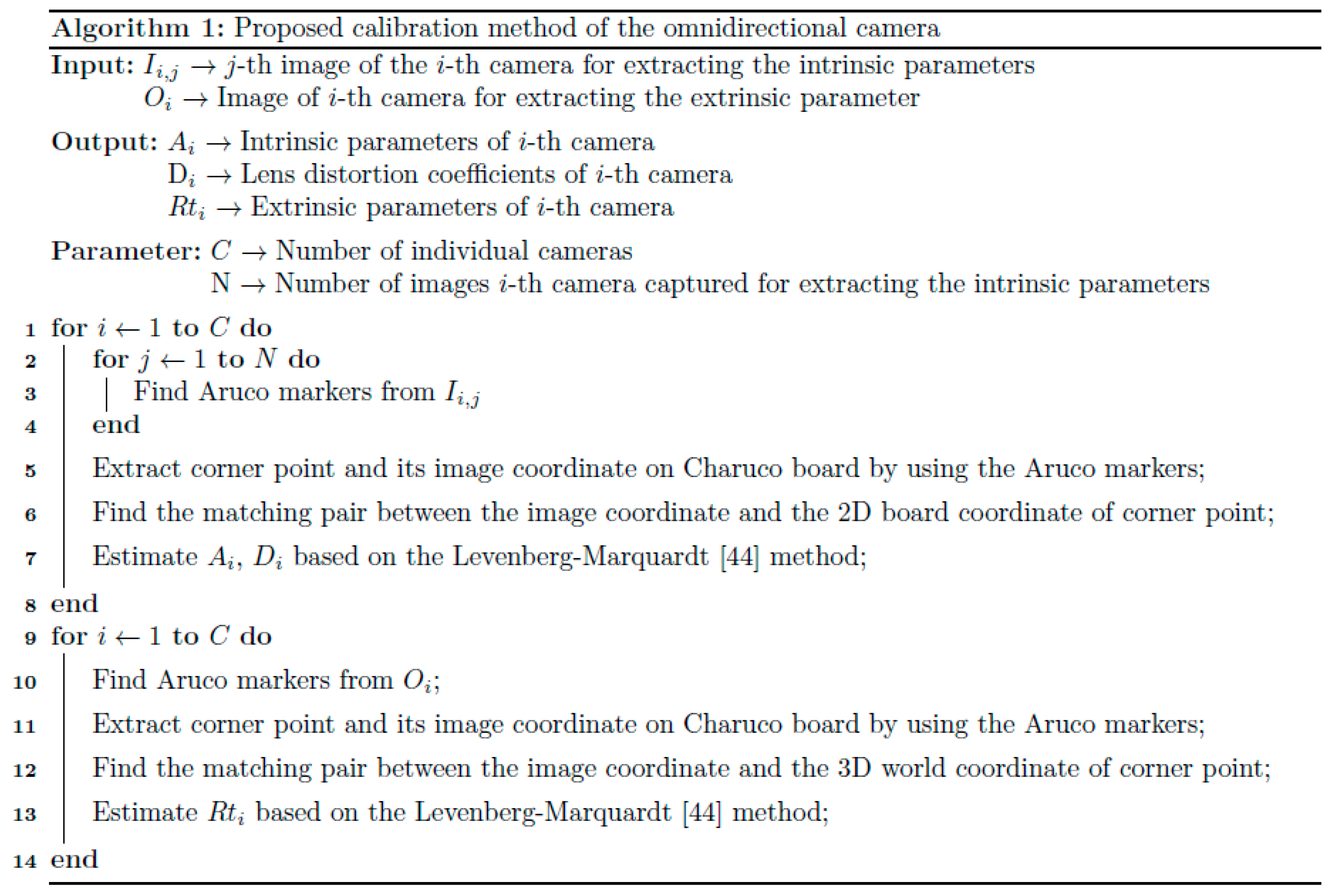
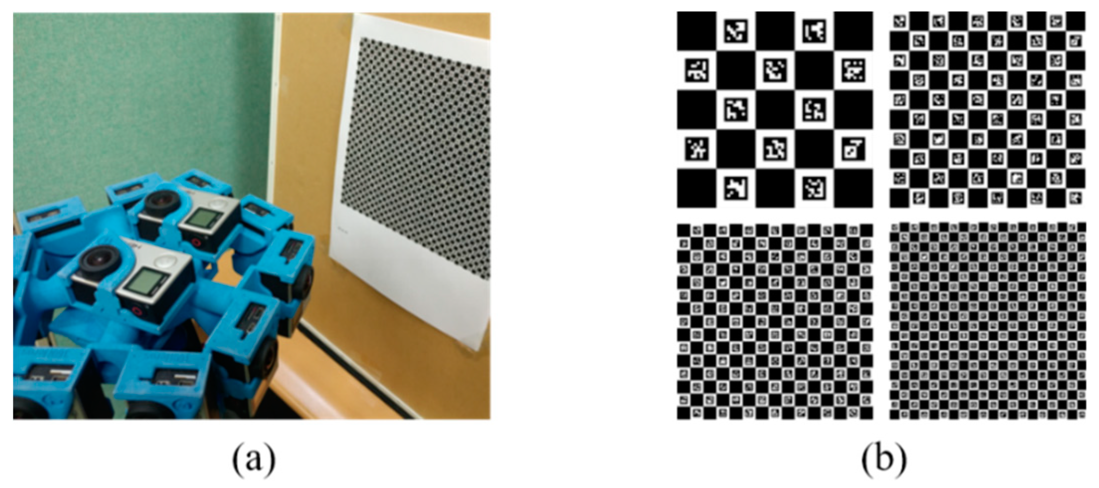
We herein propose a Charuco board-based cube structure and a method to perform both intrinsic and extrinsic calibrations of the omnidirectional camera as shown in Figure 3. We designed the proposed structure placing four different 10 × 10 grid Charuco board patterns [21] on the each face (front, back, left, and right) of the 60 × 60 × 60 cm 3 acrylic material cube. The length and orthogonality were obtained using an accuracy of 0.02 mm Vernier calipers and 0.0573° vertical meter, respectively. The Charuco board is a combination of Aruco markers [21] and a chess board, where the Aruco markers can support the distinction of the designated 3D coordinates of corner points on the chessboard via their marker identification (ID). Therefore, if only a part of the calibration structure (e.g., an Aruco marker) is included in the captured image, it becomes possible to calibrate the intrinsic parameters. Furthermore, without an additional calibration structure, extrinsic calibration can be performed to estimate the absolute 3D position difference (rotation and translation). Compared to the conventional methods, the proposed method increases reliability, because it does not require the additional adjustments to the angle of the mirror or the positions of several pattern boards. Additionally, the proposed method can calibrate the omnidirectional camera independently regardless of the number of cameras constituting the omnidirectional camera or the camera rig structure. Moreover, with applying the cube structure, calculating the rotation and the translation between the world coordinate system and the camera coordinate system is less complicated than conventional methods, because it can provide a Cartesian coordinate with the high reliability. The overall process of the proposed method is shown as Figure 4 and Algorithm 1. Proposed method consists of three steps: (1) intrinsic calibration, (2) extrinsic calibration, and (3) visualization of the camera position. Our algorithm searches Aruco markers and corner points in the given input images to identify the 2D board coordinate and the 3D world coordinate of the corner points. Then, it finds the matching pair and solves the non-linear least-squares problems to estimate the optimal parameters. A detailed description of the algorithm is given in the next section.
Electronics 07 00421 i001

3.2. Intrinsic Parameters Estimation of the Omnidirectional Camera

The principle of estimating intrinsic parameters is as follows. By considering the actual board–square length and the ratio of the Aruco marker and the Charuco board, we can designate the world coordinates of each corner point in advance. For the individual camera calibration, we place the omnidirectional camera inside the proposed calibration structure, as shown in Figure 5. Regardless of the center of the structure, the omnidirectional camera can be positioned where it can capture at least one Aruco marker in the pattern, considering the focal length and illuminance conditions. Then, the inside of the structure is captured by rotating the rig around the center of the tripod. In this case, at least two images having a common feature point must be captured to estimate the intrinsic parameters. From the captured images, we proceed corner-point detection and designate the 2D board coordinate of the detected corner point by using the near-marker ID information. Then, we match the 2D board coordinate and the image coordinate of the same corner point and estimate the intrinsic parameters. Specifically, let C A M i be the individual camera, and I j , j = 1 , , N be the one of N images captured by C A M i . The detection processes for the corner points and the Aruco marker ID are performed on I j , and the 2D board coordinate of the corner point, P , is designated as shown in Figure 5. (Refer to Garrido-Jurado et al. [21] for more details on marker detection.) For the Aruco marker ID, k , the top-left corner point’s board coordinate is designated as ( k , 1 ) , and the top-right corner point’s board coordinate is designated as ( k , 2 ) , and so on. Additionally, considering the lens distortion model, the relationship between the image coordinate, P = ( x , y ) , normalized image coordinate, P n = ( x n , y n ) , and distorted normalized image coordinate, P d n = ( x d n , y d n ) , of the corner point can be expressed in Equations (2) and (3). Based on the pinhole camera model, normalized image coordinate point, P n = ( x n , y n ) , is distorted by the lens before projection to the image sensor. We only consider the radial and tangential distortion of the lens, approximated through Taylor series as in Equation (2). And we do not consider the fisheye lens distortion model which covers up to 180°. Then, the distorted normalized image coordinate point, P d n = ( x d n , y d n ) , is multiplied by the camera matrix, A , to obtain the image coordinate point, P = ( x , y ) , as in Equation (3). After detecting M corner points in image I j , for the paired image coordinate P m = ( x m , y m ) and the distorted normalized image coordinate P m _ d n = ( x m _ d n , y m _ d n ) of each corner point P m , m = 1 , , M , we set the optimal camera matrix, A i * , of C A M i to minimize the reprojection error in Equation (4). In the proposed method, we use the Levenberg–Marquardt method [44] to find the optimal parameters. And we set a skew coefficient, s k e w _ c , as zero since the image sensor array is solid state.
D ( x n , y n ) = [ x d n y d n ] = ( 1 + k 1 ( r n ) 2 + k 2 ( r n ) 4 + k 3 ( r n ) 6 ) [ x n y n ] + [ 2 p 1 x n y n + p 2 { ( r n ) 2 + 2 ( x n ) 2 } p 1 { ( r n ) 2 + 2 ( y n ) 2 } + 2 p 2 x n y n ] ( ( r n ) 2 = ( x n ) 2 + ( y n ) 2 )
[ x y 1 ] = [ f x s k e w _ c c x 0 f y c y 0 0 1 ] [ x d n y d n 1 ] = A [ x d n y d n 1 ] = A D ( x n , y n , 1 )
where D is a lens distortion model, k 1 , k 2 , and k 3 are radial distortion coefficients, p 1 and p 2 are tangential distortion coefficients, and r n is the Euclidean distance from a principal point on the normalized image coordinate.
After detecting M corner points in image I j , for the paired image coordinate P m = ( x m , y m ) and the normalized image coordinate P m _ n = ( x m _ n , y m _ n ) of each corner point P m , m = 1 , , M , we set the optimal camera matrix A i * and the optimal lens distortion D i * of C A M i to minimize the reprojection error in Equation (4). In the proposed method, we use the Levenberg-Marquardt method [44] to find the optimal parameters.
A i * , D i * = arg min A , D [ m = 1 M E r e p { P m , A D ( P m _ n ) } 2 ]
where E r e p is a reprojection error between two points, P m and A D ( P m _ n ) .

3.3. Estimation of Extrinsic Parameters Using Estimated Intrinsic Parameters

For omnidirectional camera extrinsic calibration, we fix the camera rig and arrange the proposed calibration structure to capture the images one-by-one for each camera. After finding the corner points of the Charuco board from the captured images, we find the mapping relation between the 2D image coordinate and the 3D world coordinate of the corner points. For the image coordinate and 3D world coordinate of the specific corner point, the relationship between these coordinates can also be expressed as in Equation (1).
Specifically, for the camera C A M i , after detecting M corner points in the image, the paired image coordinate P m = ( x m , y m ) and the 3D world coordinate P m _ w o r l d = ( X m _ w o r l d , Y m _ w o r l d , Z m _ w o r l d ) of each corner point P m , m = 1 , , M , is set as the extrinsic parameters of C A M i , which minimizes the Euclidean distance in Equation (5). Here, we use the camera matrix A i * and the lens distortion D i * , estimated in Section 3.2. Then, we use the Levenberg-Marquardt method [44] to find the optimal solution, R i * and t i * , to map the image coordinate and 3D world coordinate pairs. Finally, we obtain the rotation and translation information of each camera:
R i * , t i * = arg min R , t [ m = 1 M d { P m , A i * D i * ( [ R | t ] P m _ w o r l d ) } 2 ]
where d is a Euclidean distance between two points, P m and A i * D i * ( [ R | t ] P m _ w o r l d ) .

4. Experimental Setting and Result

4.1. Experiment on Proper Size of Calibration Pattern Unit

Before executing a proposed calibration experiment, we conducted the experiment on the proper size of the used pattern unit to improve the detection of the marker in the proposed calibration structure. The pattern unit means one white square containing the Aruco marker on the Charuco board. Since the resolution, FoV, and distance from the pattern of the camera are changed every time, it is difficult to derive the physical scale (mm) for the proper size of the pattern unit in the captured image.
Therefore, we derived the appropriate size of pattern unit on pixel scale. For the experiment, the distance between the camera and the pattern, and the size of the Charuco board were kept constant as shown in Figure 6a. The size of the pattern unit was adjusted and captured as shown in Figure 6b. Also, as the main purpose of the Charuco board is to provide the feature points, the accuracy was derived from the correctly detected number of corner points compared to the actual number of corner points in the captured image. Additionally, the camera was rotated and 10 images were taken for each pattern at various angles. The experimental results are shown in Table 1. The accuracy of the detected corner point was 97% or more when the length of one pattern unit in the captured image exceeds about 100 pixels. As a result, without the consideration for camera resolution, FoV, and distance from the pattern, we required the length occupying more than 100 pixels in the captured image for the accurate calibration.

4.2. Experimental Setting and Process

We experimented with the proposed omnidirectional camera calibration structure. In the experiment, we used a camera rig with 360° horizontal coverage. Additionally, we used a pentagonal rig as a target omnidirectional camera rig to combine with the five-stereo shape. Compared to the circular rig with overlapping regions, the pentagonal rig has large overlapping regions where the cameras are parallel and few overlapping regions where the cameras diverge. With the target rig, we used 10 GoPro Hero4 Blacks (GoPro Inc., San Mateo, CA, USA) [45]. The resolution of each camera was 2250 × 3000 pixels, vertical FoV was 94.4°, and horizontal FoV was 72.2°. The structure of the target rig and the overlapping area between the cameras are shown in Figure 7. During the experiment, 10 cameras were captured simultaneously using the remote controller provided by GoPro. For the proposed calibration and the visualization of the calibration results, OpenCV camera calibration example code [46], Charuco library [47], and the camera calibration toolbox for Matlab [48] were used, respectively.
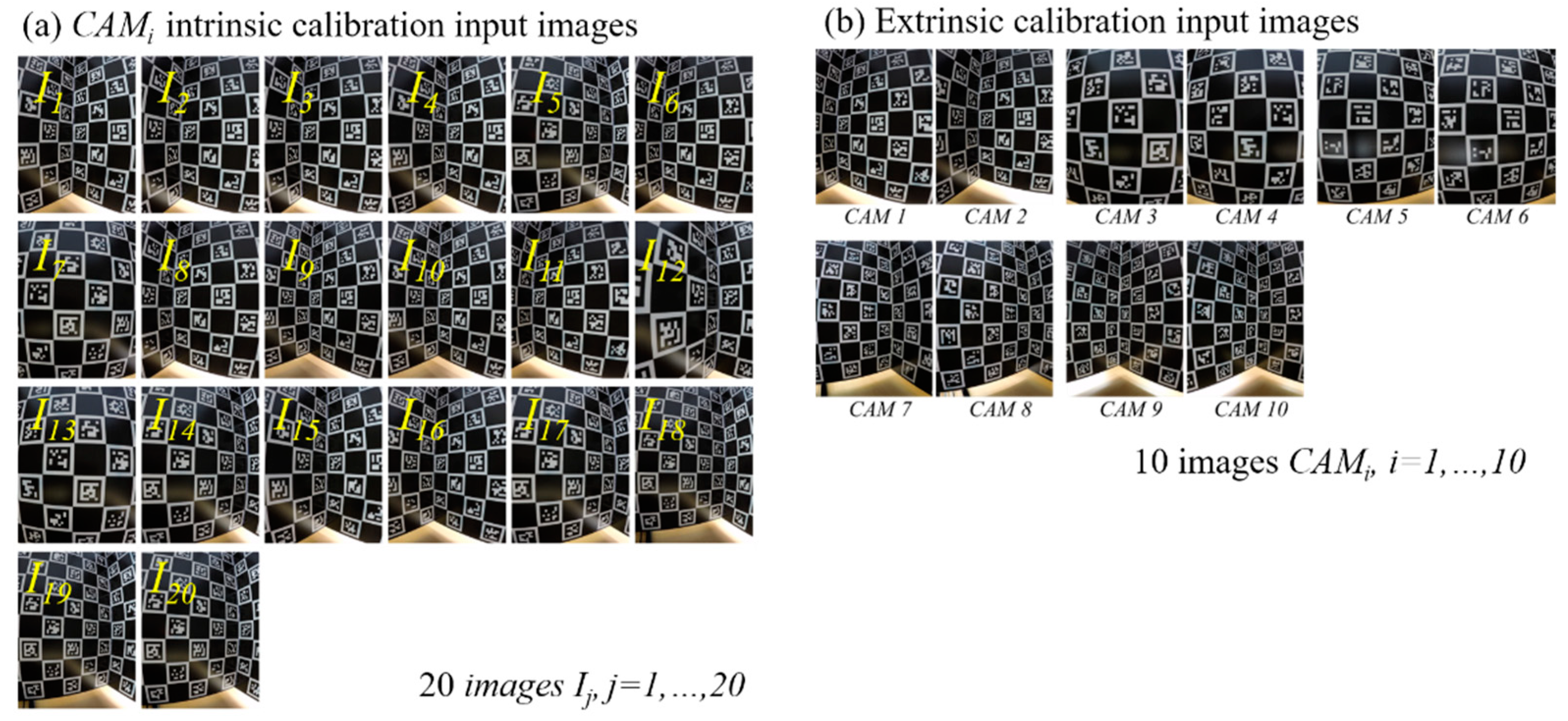
For the intrinsic calibration of the omnidirectional camera, the camera rig was placed in the proposed calibration structure. By rotating the rig, 20 images were obtained for each camera, as shown in Figure 8a. Then, we obtained the intrinsic parameters of each camera that minimized the reprojection error for the 20 images of that camera. Next, for the extrinsic calibration, the camera rig was fixed in the proposed structure. We then captured one image for each camera, as shown in Figure 8b. For the captured images, we obtained the extrinsic parameters of each camera to minimize the Euclidean distance. Then, based on the estimated rotation and translation information, the position of the individual camera constituting the rig was visualized in a 3D space.

4.3. Experimental Results

The performance evaluation of the proposed calibration method was divided into two parts: (i) accuracy of the intrinsic parameters and (ii) accuracy of the extrinsic parameters. First, the accuracy of the intrinsic parameters of the individual cameras constituting the omnidirectional camera were evaluated. After detecting the feature points for 20 images of 10 cameras, we calculated the average reprojection error for each camera through the estimated intrinsic parameters of (4). Additionally, we compared the proposed method with Zhang’s method [25] which is the one of the commonly-used conventional camera calibration methods, and with the method of Li et al. [31] which uses a random pattern as an invariant feature to calibrate even if the image is partially captured. Using Zhang’s and Li et al.’s methods, we captured 20 images of their pattern, and we compared the average reprojection error, as shown in Table 2 and Figure 9a. For 10 cameras, the average reprojection error of the proposed method was 0.37 pixels: 0.2 pixels fewer than Zhang’s method, and 0.3 pixels fewer than Li et al.’s method. Additionally, unlike Zhang’s method, it was possible to calibrate, even if the entire pattern board had not been captured at the image. Therefore, it was confirmed that intrinsic calibration of the omnidirectional camera is possible without the problems of the conventional method, where the same procedure must be repeated for each camera.
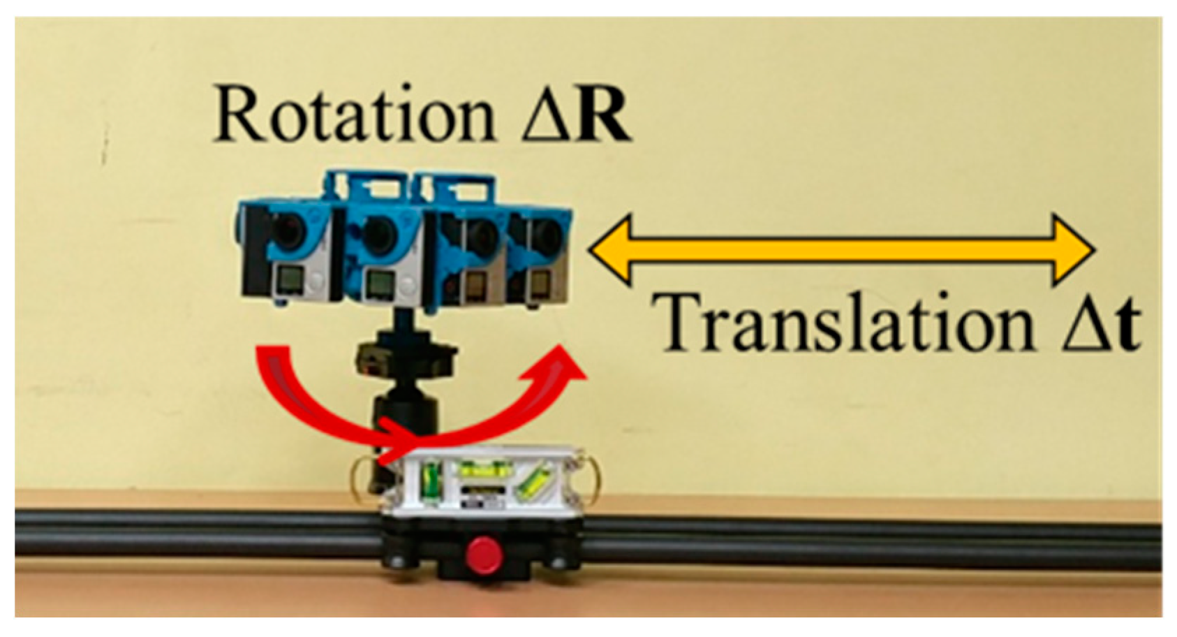
Second, the accuracy of the estimated extrinsic parameters was evaluated. Because obtaining the ground truth of the 3D world coordinate system of the camera is difficult, we rotated and translated the camera rig, as in Figure 10. We compared it with the calculated displacement via estimated extrinsic calibration. The rig was rotated in 60 ° increments and translated at 30-mm increments. The result of extrinsic calibration is more accurate when the mean absolute error is closer to zero. The experimental results for each of the rotations and translations are shown in Table 3 and Table 4, and Figure 9b,c, respectively. From the results, we can see that the rotation error and the translation error were about 0.90 ° and 1.32 mm, respectively. Additionally, we confirmed the visualization results. The posture of multiple cameras can be easily confirmed by visualizing the estimated pose of each camera in three dimensions. We used the estimated extrinsic parameters (e.g., translation and rotation vectors) to allow for additional alignments (e.g., pan and tilt) of the individual camera constituting the omnidirectional camera. For the given position of the omnidirectional camera, as Figure 11a, we visualized the calibration results of the proposed method as in Figure 11b. To compare the proposed calibration method, we proceeded with a chain-wise stereo camera calibration and visualized the result using relative rotation and translation information of the adjacent camera, such as CAM1-CAM2, CAM2-CAM3, CAM3-CAM4, etc. The proposed method visualized the shape of the pentagon more clearly, as shown in Figure 11c. When using the chain-wise method, the positional error increased, because errors accumulated, as shown in the circles of Figure 11c. However, because the proposed method estimated the rotation and translation independently for each camera, the positional error is relatively smaller.
To show the validity of the proposed method on the VR application, we used Autopano Giga 4.4 [49] which mainly aims to the omnidirectional image stitching. Image stitching needs not only extrinsic parameters of each camera, but also additional warping to get the result without cognitive distortion. However, we applied the result of our method only using the extrinsic parameter results without any additional processing as shown in Figure 12. To visualization, we only contain the result images of the odd-numbered cameras among 10 cameras. The blue circles shows the images are well-connected, and the red circles shows the images are disconnected which causes cognitive distortion.

5. Conclusions

A Charuco board-based omnidirectional camera calibration method and structure is herein proposed to solve the problem where conventional camera calibration methods require too many complicated procedures. In the case of the omnidirectional camera, it must be comprised of several cameras to collect 360° information around the rig. Additionally, the calibration among these cameras should be preceded. Accurate calibration is essential to increase that of omnidirectional image processing, such as extracting depth information from captured images. An omnidirectional camera structure has a form in which the center line of each camera diverges. Therefore, it is difficult to share one another’s coordinate space. Additionally, because calibration must be repeated according to the number of individual cameras comprising the omnidirectional camera, it takes a long time. To solve these problems, we proposed an omnidirectional camera calibration method and structure that can provide distinguishable 3D world coordinates and 2D board coordinates. From the experimental results, for the intrinsic parameters, the proposed method yielded an average reprojection error of 0.37 pixels, higher than the conventional method. For the extrinsic parameters, the proposed method had a mean absolute error of 0.90° for the rotation displacement and a mean absolute error of 1.32 mm for the translation displacement. We expect that the proposed method could be the basis of omnidirectional image processing for acquiring 6-DoF in the future.

Author Contributions

G.H.A., S.L., M.-W.S. and S.-J.K. conceived and designed the experiments; G.H.A., S.L., and S.-J.K. performed the experiments, and analyzed the data; G.H.A., S.L., M.-W.S., K.Y., W.-S.C. and S.-J.K. contributed the equipment development; G.H.A. and S.-J.K. wrote the paper.

Acknowledgments

This work was supported by Institute for Information and communications Technology Promotion (IITP) grant funded by the Korea government (MSIT) (No. 2017-0-00072, Development of Audio/Video Coding and Light Field Media Fundamental Technologies for Ultra Realistic Tera-media), and supported by the National Research Foundation of Korea (NRF) grant funded by the Korea government (MSIT) (no. 2018R1D1A1B07048421).

Conflicts of Interest

The authors declare no conflict of interest.

References

  1. Agrawal, A.; Taguchi, Y.; Ramalingam, S. Analytical forward projection for axial non-central dioptric and catadioptric cameras. In Proceedings of the European Conference on Computer Vision, Crete, Greece, 5–11 September 2010; pp. 129–143. [Google Scholar]
  2. Scaramuzza, D. Omnidirectional camera. In Computer Vision; Springer: Berlin, Germany, 2014; pp. 552–560. [Google Scholar]
  3. Xiang, Z.; Sun, B.; Dai, X. The camera itself as a calibration pattern: A novel self-calibration method for non-central catadioptric cameras. Sensors 2012, 12, 7299–7317. [Google Scholar] [PubMed]
  4. Valiente, D.; Payá, L.; Jiménez, L.; Sebastián, J.; Reinoso, Ó. Visual information fusion through bayesian inference for adaptive probability-oriented feature matching. Sensors 2018, 18, 2041. [Google Scholar] [CrossRef]
  5. Junior, J.M.; Tommaselli, A.M.G.; Moraes, M.V.A. Calibration of a catadioptric omnidirectional vision system with conic mirror. ISPRS J. Photogramm. Remote Sens. 2016, 113, 97–105. [Google Scholar] [CrossRef]
  6. Neumann, J.; Fermuller, C.; Aloimonos, Y. Polydioptric camera design and 3D motion estimation. In Proceedings of the 2003 IEEE Computer Society Conference on Computer Vision and Pattern Recognition, Madison, WI, USA, 18–20 June 2003; Volume 2. [Google Scholar]
  7. Yin, L.; Wang, X.; Ni, Y.; Zhou, K.; Zhang, J. Extrinsic Parameters Calibration Method of Cameras with Non-Overlapping Fields of View in Airborne Remote Sensing. Remote Sens. 2018, 10, 1298. [Google Scholar] [CrossRef]
  8. Nuger, E.; Benhabib, B. A Methodology for Multi-Camera Surface-Shape Estimation of Deformable Unknown Objects. Robotics 2018, 7, 69. [Google Scholar]
  9. Chen, J.; Benzeroual, K.; Allison, R.S. Calibration for high-definition camera rigs with marker chessboard. In Proceedings of the 2012 IEEE Computer Society Conference on Computer Vision and Pattern Recognition Workshops (CVPRW), Providence, RI, USA, 16–21 June 2012; pp. 29–36. [Google Scholar]
  10. Facebook Surround 360. Available online: https://developers.facebook.com/videos/f8-2017/surround-360-beyond-stereo-360-cameras/ (accessed on 7 November 2018).
  11. Jump-Google VR. Available online: https://vr.google.com/jump/ (accessed on 7 November 2018).
  12. Ricoh Theta. Available online: https://theta360.com/ (accessed on 7 November 2018).
  13. Samsung Gear 360. Available online: http://www.samsung.com/global/galaxy/gear-360/ (accessed on 7 November 2018).
  14. Sonka, M.; Hlavac, V.; Boyle, R. Image Processing, Analysis, and Machine Vision; Cengage Learning: Boston, MA, USA, 2014. [Google Scholar]
  15. Duane, C.B. Close-range camera calibration. Photogramm. Eng. 1971, 37, 855–866. [Google Scholar]
  16. Kenefick, J.F.; Gyer, M.S.; Harp, B.F. Analytical self-calibration. Photogramm. Eng. 1972, 38, 1117–1126. [Google Scholar]
  17. Clarke, T.A.; Fryer, J.G. The development of camera calibration methods and models. Photogramm. Rec. 1998, 16, 51–66. [Google Scholar] [CrossRef]
  18. Habib, A.; Detchev, I.; Kwak, E. Stability analysis for a multi-camera photogrammetric system. Sensors 2014, 14, 15084–15112. [Google Scholar] [CrossRef]
  19. Detchev, I.; Habib, A.; Mazaheri, M.; Lichti, D. Practical in situ Implementation of a Multicamera Multisystem Calibration. J. Sens. 2018, 2018. [Google Scholar] [CrossRef]
  20. Hartley, R.; Zisserman, A. Multiple View Geometry in Computer Vision; Cambridge University Press: Cambridge, UK, 2003. [Google Scholar]
  21. Garrido-Jurado, S.; Muñoz-Salinas, R.; Madrid-Cuevas, F.J.; Marin-Jiménez, M.J. Automatic generation and detection of highly reliable fiducial markers under occlusion. Pattern Recognit. 2014, 47, 2280–2292. [Google Scholar] [CrossRef]
  22. Muñoz-Salinas, R.; Marin-Jimenez, M.J.; Yeguas-Bolivar, E.; Medina-Carnicer, R. Mapping and localization from planar markers. Pattern Recognit. 2018, 73, 158–171. [Google Scholar] [CrossRef] [Green Version]
  23. Germanese, D.; Leone, G.; Moroni, D.; Pascali, M.; Tampucci, M. Long-Term Monitoring of Crack Patterns in Historic Structures Using UAVs and Planar Markers: A Preliminary Study. J. Imaging 2018, 4, 99. [Google Scholar] [CrossRef]
  24. Tsai, R.Y. An efficient and accurate camera calibration technique for 3D machine vision. Proc. Comp. Vis. Patt. Recog. 1986, 364–374. [Google Scholar]
  25. Zhang, Z. A flexible new technique for camera calibration. IEEE Trans. Pattern Anal. Mach. Intell. 2000, 22, 1330–1334. [Google Scholar] [CrossRef] [Green Version]
  26. Tang, D.; Hu, T.; Shen, L.; Ma, Z.; Pan, C. AprilTag array-aided extrinsic calibration of camera--laser multi-sensor system. Robot. Biomim. 2016, 3, 13. [Google Scholar] [CrossRef] [PubMed]
  27. Dong, S.; Shao, X.; Kang, X.; Yang, F.; He, X. Extrinsic calibration of a non-overlapping camera network based on close-range photogrammetry. Appl. Opt. 2016, 55, 6363–6370. [Google Scholar] [CrossRef] [PubMed]
  28. Carrera, G.; Angeli, A.; Davison, A.J. SLAM-based automatic extrinsic calibration of a multi-camera rig. In Proceedings of the 2011 IEEE International Conference on Robotics and Automation (ICRA), Shanghai, China, 9–13 May 2011; pp. 2652–2659. [Google Scholar]
  29. Olson, E. AprilTag: A robust and flexible visual fiducial system. In Proceedings of the 2011 IEEE International Conference on Robotics and Automation (ICRA), Shanghai, China, 9–13 May 2011; pp. 3400–3407. [Google Scholar]
  30. Davison, A.J.; Reid, I.D.; Molton, N.D.; Stasse, O. MonoSLAM: Real-time single camera SLAM. IEEE Trans. Pattern Anal. Mach. Intell. 2007, 1052–1067. [Google Scholar] [CrossRef]
  31. Li, B.; Heng, L.; Koser, K.; Pollefeys, M. A multiple-camera system calibration toolbox using a feature descriptor-based calibration pattern. In Proceedings of the 2013 IEEE/RSJ International Conference on Intelligent Robots and Systems (IROS), Tokyo, Japan, 3–7 November 2013; pp. 1301–1307. [Google Scholar]
  32. Strauß, T.; Ziegler, J.; Beck, J. Calibrating multiple cameras with non-overlapping views using coded checkerboard targets. In Proceedings of the 2014 IEEE 17th International Conference on Intelligent Transportation Systems (ITSC), Qingdao, China, 8–11 October 2014; pp. 2623–2628. [Google Scholar]
  33. Yu, L.; Han, Y.; Nie, H.; Ou, Q.; Xiong, B. A calibration method based on virtual large planar target for cameras with large FOV. Opt. Lasers Eng. 2018, 101, 67–77. [Google Scholar] [CrossRef]
  34. Fraser, C.S. Automated processes in digital photogrammetric calibration, orientation, and triangulation. Digit. Signal Process. 1998, 8, 277–283. [Google Scholar] [CrossRef]
  35. Fraser, C.S. Automatic camera calibration in close range photogrammetry. Photogramm. Eng. Remote Sens. 2013, 79, 381–388. [Google Scholar] [CrossRef]
  36. Lowe, D.G. Distinctive image features from scale-invariant keypoints. Int. J. Comput. Vis. 2004, 60, 91–110. [Google Scholar] [CrossRef]
  37. Kumar, R.K.; Ilie, A.; Frahm, J.-M.; Pollefeys, M. Simple calibration of non-overlapping cameras with a mirror. In Proceedings of the IEEE Conference on CVPR 2008 Computer Vision and Pattern Recognition, Anchorage, AK, USA, 23–28 June 2008; pp. 1–7. [Google Scholar]
  38. Miyata, S.; Saito, H.; Takahashi, K.; Mikami, D.; Isogawa, M.; Kojima, A. Extrinsic camera calibration without visible corresponding points using omnidirectional cameras. IEEE Trans. Circuits Syst. Video Technol. 2018, 28, 2210–2219. [Google Scholar] [CrossRef]
  39. Zhu, C.; Zhou, Z.; Xing, Z.; Dong, Y.; Ma, Y.; Yu, J. Robust plane-based calibration of multiple non-overlapping cameras. In Proceedings of the 2016 Fourth International Conference on 3D Vision (3DV), Stanford, CA, USA, 25–28 October 2016; pp. 658–666. [Google Scholar]
  40. Tommaselli, A.M.G.; Galo, M.; De Moraes, M.V.A.; Marcato, J.; Caldeira, C.R.T.; Lopes, R.F. Generating virtual images from oblique frames. Remote Sens. 2013, 5, 1875–1893. [Google Scholar] [CrossRef]
  41. Tommaselli, A.M.G.; Marcato, J., Jr.; Moraes, M.V.A.; Silva, S.L.A.; Artero, A.O. Calibration of panoramic cameras with coded targets and a 3D calibration field. Int. Arch. Photogramm. Remote Sens. Spat. Inf. Sci. 2014, 40, 137–142. [Google Scholar] [CrossRef]
  42. Campos, M.B.; Tommaselli, A.M.G.; Marcato Junior, J.; Honkavaara, E. Geometric model and assessment of a dual-fisheye imaging system. Photogramm. Rec. 2018, 33, 243–263. [Google Scholar] [CrossRef]
  43. Khoramshahi, E.; Honkavaara, E. Modelling and automated calibration of a general multi-projective camera. Photogramm. Rec. 2018, 33, 86–112. [Google Scholar] [CrossRef]
  44. Marquardt, D.W. An algorithm for least-squares estimation of nonlinear parameters. J. Soc. Ind. Appl. Math. 1963, 11, 431–441. [Google Scholar] [CrossRef]
  45. GoPro Hero4 Black. Available online: https://gopro.com/ (accessed on 7 November 2018).
  46. Camera Calibration with OpenCV. Available online: https://docs.opencv.org/3.4.0/d4/d94/tutorial_camera_calibration.html (accessed on 7 November 2018).
  47. Calibration with ArUco and ChArUco. Available online: https://docs.opencv.org/3.4/da/d13/tutorial_aruco_calibration.html (accessed on 7 November 2018).
  48. Camera Calibration Toolbox for Matlab. Available online: http://www.vision.caltech.edu/bouguetj/calib_doc/ (accessed on 7 November 2018).
  49. Kolor Autopano. Available online: http://www.kolor.com/ (accessed on 29 November 2018).
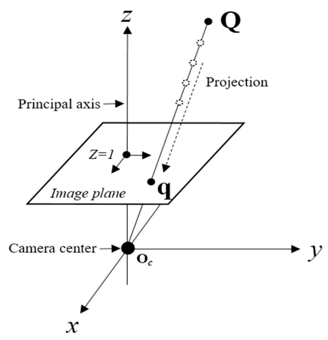
Figure 1. Pinhole camera model and perspective projection transformation.
Electronics 07 00421 g001
Figure 2. (a) Epipolar geometry of the stereo camera structure and (b) multi-view polydioptric omnidirectional camera structures.
Electronics 07 00421 g002
Figure 3. Charuco board pattern [21] and the structure of the proposed omnidirectional camera calibration.
Electronics 07 00421 g003
Figure 4. Overall flowchart of the proposed omnidirectional camera calibration.
Electronics 07 00421 g004
Figure 5. Acquisition of corner point coordinates from omnidirectional camera images and the Aruco marker.
Electronics 07 00421 g005
Figure 6. (a) Experimental setting to find proper size of calibration pattern unit and (b) the Charuco board with various sizes.
Electronics 07 00421 g006
Figure 7. Target omnidirectional camera rig structure and field of view coverage.
Electronics 07 00421 g007
Figure 8. Captured image data for extracting (a) intrinsic parameters and (b) extrinsic parameters.
Electronics 07 00421 g008
Figure 9. The measurement results of proposed method: (a) reprojection error; (b) rotation mean absolute error; and (c) translation mean absolute error.
Electronics 07 00421 g009
Figure 10. Rotation and translation movement for evaluation of extrinsic calibration accuracy.
Electronics 07 00421 g010
Figure 11. Visualization of 3D position space of omnidirectional camera: (a) position of the omnidirectional camera; (b) visualization result of the proposed method; and (c) comparison with the chain-wise method.
Electronics 07 00421 g011
Figure 12. Result of the proposed method on the VR application: image stitching.
Electronics 07 00421 g012
Table 1. Corner points detection accuracy of various sized Charuco boards.
The Total Number of Patterns in the Given Area 5 × 5 10 × 10 1 5 × 15 20 × 20 2 5 × 25
Pattern unit length (Unit: pixel)37019013010080
The number of actual corner points in the captured image1681196361576
The number of correctly detected corner points in the captured image1678.91194.64353.82524.27
Accuracy (%)100.097.4299.3098.0191.02
Table 2. The reprojection error of proposed method and conventional method.
(Unit: pixel)CAM1CAM2CAM3CAM4CAM5CAM6CAM7CAM8CAM9CAM10 m σ
Proposed0.310.440.360.360.360.480.420.470.230.290.370.08
Zhang [25]0.480.440.470.460.500.510.640.620.540.510.520.07
Li et al. [31]0.590.790.570.610.610.590.610.680.580.540.620.07
Table 3. The rotation mean absolute error of measurement results.
Rotation Displacement Value (Degree)60120180240300
Measurement resultsCAM159.81119.48180.47240.79299.30
CAM261.56119.57181.06242.66299.18
CAM360.12121.10180.43241.21300.73
CAM460.23121.11180.44241.22300.82
CAM559.78120.94180.51240.74300.52
CAM662.25120.25180.43243.28299.67
CAM759.34120.87180.38240.08300.45
CAM859.35120.91180.82240.21300.51
CAM961.65121.51180.09242.28301.39
CAM1061.44121.39180.00242.27301.20
Mean absolute error0.900.900.461.480.75
Standard deviation0.760.410.311.090.33
Table 4. The translation mean absolute error of measurement results.
Translation Displacement Value (mm)306090120150180210
Measurement resultsCAM133.1660.9890.90121.61151.32181.14211.59
CAM230.6261.5690.86121.78151.07181.27212.17
CAM331.2462.6490.71121.46151.97181.75211.63
CAM431.1161.1991.23121.11151.41181.27211.86
CAM529.0363.6190.92121.64151.47181.32212.24
CAM630.9060.5491.17117.24151.38179.90210.37
CAM731.1061.1290.73121.42151.44181.02211.89
CAM830.8360.7991.32121.57151.24181.65210.17
CAM930.8360.7991.32121.57151.24181.65210.17
CAM1031.7461.3091.07122.02150.31181.61211.62
Mean absolute error1.251.451.021.691.281.181.37
Standard deviation0.740.950.230.440.410.470.81