Article

Design and Validation of EASYbot: An Open, Scalable and Modular Platform for Educational Robotics


by
Jonathan Ruiz-de-Garibay
1,*,
Pablo Garaizar
1 and
Susana Romero-Yesa
2
1
Deustek, University of Deusto, 48007 Bilbao, Spain
2
DeustoMED, University of Deusto, 48007 Bilbao, Spain
*
Author to whom correspondence should be addressed.
Electronics 2026, 15(8), 1650; https://doi.org/10.3390/electronics15081650
Submission received: 12 March 2026 / Revised: 4 April 2026 / Accepted: 9 April 2026 / Published: 15 April 2026
(This article belongs to the Special Issue Modeling and Control of Mobile Robots)

Abstract

Educational robotics (ER) and robotics competitions offer an effective context for developing STEM (Science, Technology, Engineering, and Mathematics) competencies, technical skills, and soft skills in engineering degrees. However, current platforms reveal a pedagogical and technical gap: closed commercial systems restrict access to hardware, while open solutions frequently lack a robust and structured architecture for educational settings. Moreover, in both cases, many platforms do not achieve the hardware requirements of the most demanding competitions. To address this issue, the present article presents the design, implementation, and validation of EASYbot, a modular open-hardware robotics platform based on Arduino. The system integrates a microcontroller, a dual USB–battery power supply, high-performance motor power stages, and a plug-and-play interface for input/output and communication peripherals, enabling its use in several competition categories such as mini-sumo or maze robots. The platform is complemented by a state-based programming model and supports libraries that facilitate a learning assessment. The platform provides a scalable ecosystem, enabling students to progress from initial prototyping to optimised hardware control. The validation process encompasses a range of assessments, including technical tests, usability, and adoption evaluation through surveys.

1. Introduction

Educational robotics (ER) has become an established pedagogical tool for developing programming, technical and scientific skills, critical thinking and problem-solving, and social and personal skills at various levels of education [1]. Thanks to its interdisciplinarity, it enables the integration of electronics, programming, control, mechanics, and embedded systems and can be easily combined with active methods such as project-based learning [2,3]. Several studies confirm that incorporating robotics into the classroom not only increases student motivation [4] but also improves their problem-solving skills and promotes the development of computational thinking [5,6]. Recent studies [7,8] demonstrate with quantitative evidence that ER produces significant improvements in the performance of these competencies compared with traditional methods.
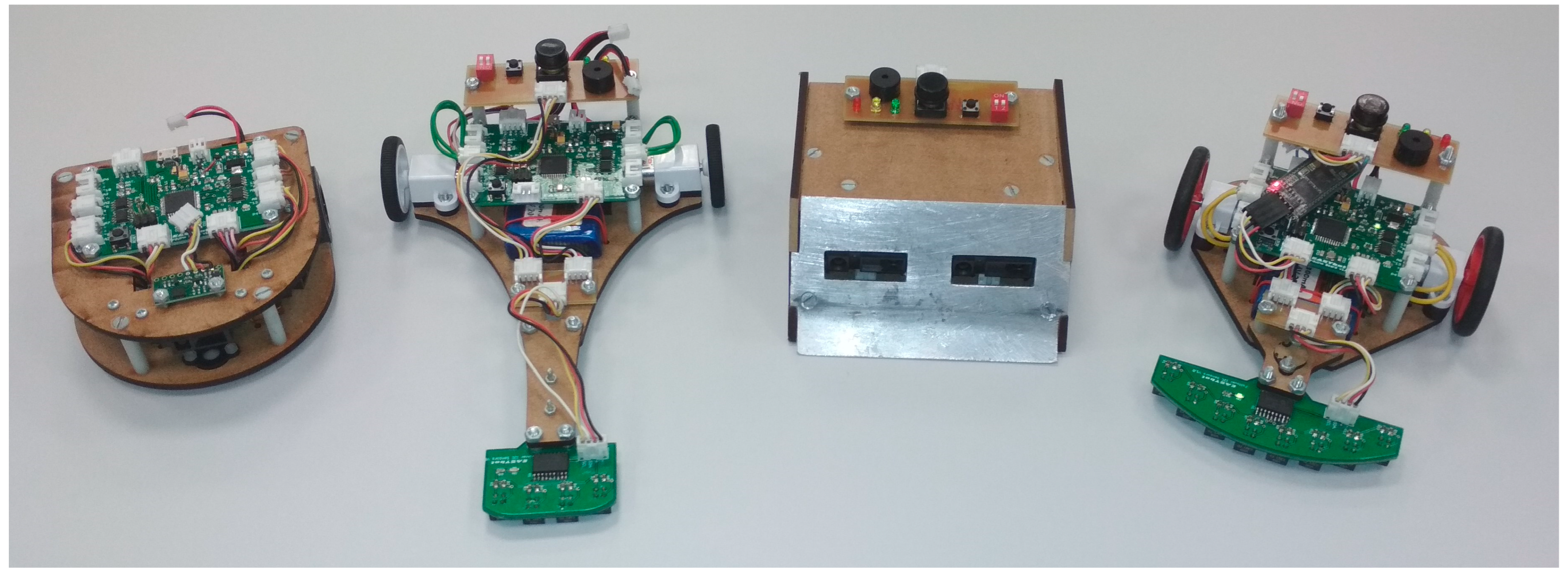
In recent decades, the use of robotics has increased significantly in both primary and secondary education [9]. In this early phase, this expansion has been supported by commercial platforms that offer an intuitive introduction to the technology. At the same time, competitive robotics has become increasingly important as an educational tool [10]. In fact, recent publications show that participation in robotics competitions has a direct and measurable impact on improving students’ interpersonal skills, project management, and self-efficacy [11]. In this context, categories such as line-follower, tracker, mini-sumo, or maze robots (see Figure 1) place demands on performance and reliability that promote the application of engineering principles such as iteration, verification, debugging, and optimisation.
This transition towards advanced technical applications is reflected in various university initiatives; for example, ref. [12] evaluates a competition robotic project with first-year university students, while ref. [13] details the design and validation of differential traction robots created specifically for teaching automatic control systems. Furthermore, it has been demonstrated that using robots to teach complex concepts, such as trochoidal curves in mathematics [14], improves conceptual understanding compared to traditional teaching methods or the use of passive multimedia resources.
However, the use of pre-configured hardware in ER platforms is not equally effective in certain higher education contexts, particularly where the system needs: (1) flexibility to adapt the robot to different contexts, (2) high performance for certain competitive environments, (3) open architectures that allow access to and modification of the hardware, (4) programming tools that facilitate the development of advanced control algorithms, and (5) adaptability to different educational levels with a clear pedagogical focus.
To meet this challenge, this article presents a competition ER platform whose design is determined not only by technical requirements but also by educational ones, as recommended in [15]. Specifically, EASYbot is proposed as an open, scalable, and modular platform that reduces initial friction while maintaining the technical depth required for higher education in the field of embedded systems. The technical and educational objectives are:
  • To ensure unrestricted access to hardware and software, enable performance optimisation, and highlight the mutual influence of electronics and programming.
  • To maintain a modular, well-documented, and robust architecture that meets the mechanical, electrical, and educational requirements of robotics competitions.
  • Development of a modular and flexible ecosystem that can be adapted to different competition categories without requiring hardware redesign.
  • Provision of a scalable solution for different educational levels, allowing the degree of abstraction and complexity of the training to be adapted to the technical knowledge level of the students.
The platform has been developed following a seven-phase methodology (see Figure 2): (1) analysis of existing robotic platforms used in education, (2) definition of technical and educational requirements, (3) design of the platform architecture, including both hardware and software principles, (4) hardware implementation, (5) technical validation, (6) deployment in educational projects, and (7) validation and assessment of educational experiences, together with iterative updates of the platform based on both technical results and educational feedback, thereby avoiding the purely technical evaluation criticised in [16].
The Section 2 provides a brief review of existing robotic platforms as educational tools. Section 3 details the defined educational and technical requirements, and Section 4 describes in depth the platform architecture, the components developed, the integration of peripherals, and the programming model. Finally, the article ends with a technical validation of the platform, an analysis of its adoption by university students, and final conclusions.
This article does not cover the design or evaluation of robot mechanics, as in most of the projects developed, the students themselves are responsible for developing this part. Furthermore, only a summary of the educational results is included, as the primary focus of this work is on the validation of the robotic platform.

2. Robotic Platforms for Educational Use

In recent decades, the catalogue of ER platforms has grown exponentially [17]. However, selecting an appropriate tool for education remains challenging, as it must balance technical depth, cost, and the learning curve [18]. Furthermore, pedagogical success does not depend only on the hardware but also on the existence of structured educational activity guides to accompany it [19].
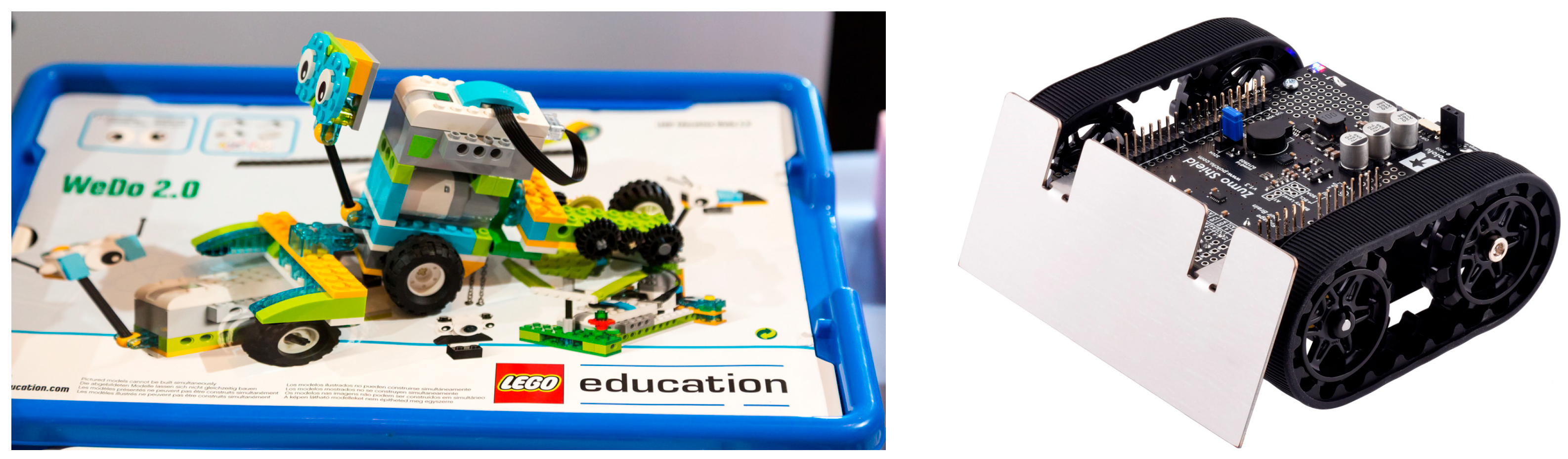
Commercial platforms such as LEGO Education (see Figure 3) or VEX Robotics have dominated primary and secondary education thanks to their plug-and-play design and visual programming environments. Although they facilitate deployment in the classroom by reducing technical barriers, their high level of abstraction limits direct access to sensor readings and low-level control. These restrictions prevent the development of optimised control algorithms, which are fundamental to engineering education.
To mitigate the gap between the visual and textual programming, hybrid environments have emerged [20,21]. These solutions allow users to switch between blocks and languages such as Python or C++, thus encouraging computational thinking. However, they often hide peripheral configuration and the temporal behaviour of the system, which are critical elements for consolidating fundamental technical knowledge.
Solutions based on open controllers such as Arduino, Raspberry Pi, or BeagleBone represent a step towards greater technical depth [22,23]. By enabling direct configuration of PWM (Pulse Width Modulation) or ADC (Analogue to Digital Converter) modules, these platforms facilitate an understanding of embedded architectures. The main advantages are high customisation, access to hardware and software repositories, and the possibility of electronic redesign. However, they generally lack standardised educational architecture. Many open-source robots (Doodlebot [24], underwater robots [25], or FOSSBot [26]) are designed for specific applications, requiring complete redesigns if the context of use changes. For example, Figure 3 shows the Pololu Zumo robot, which is designed for the mini-sumo category, but it is not possible to reuse it in other categories.
Competitions are highly demanding environments that demand temporal determinism and mechanical robustness. Currently, there is a critical gap, as closed platforms lack the necessary hardware flexibility, and advanced frameworks (such as ROS), used in some platforms, introduce excessive architectural complexity for compact systems based on microcontrollers with real-time requirements [27].
The state-of-the-art analysis, therefore, reveals a clear gap: there is no educational platform specifically designed for competition robotics that simultaneously integrates open hardware, a modular architecture, a plug-and-play peripheral system, and a coherent progressive pedagogical structure. This shortcoming justifies the need for new proposals that combine the advantages of open platforms with an accessible, scalable educational structure oriented towards robotics competitions.

3. Platform Requirements

To develop a platform that bridges the gap identified in the current state of the art between commercial educational kits and open-source systems, it is essential to establish a clear requirements framework. Given the educational focus of this work, the requirements are not limited to hardware and software specifications but also incorporate criteria related to scalability, modularity, and learning usability, so that the platform can be adapted to different learning levels without sacrificing access and understanding of the system’s internal workings. Consequently, the requirements are organised into three blocks: (1) educational requirements, (2) technical requirements, and (3) usability and professional requirements.

3.1. Educational Requirements

The platform must enable comprehensive training in the three key areas of robotics: electronics, programming, and embedded systems. To this end, it must enable students to (1) understand the electronic functioning of sensors, (2) control the motor power stages, and (3) understand power supply systems under real operating conditions. Students must be able to move from (4) block-based visual programming to (5) structured programming in high-level languages, including more advanced aspects such as (6) object-oriented programming and (7) event control. Taken together, this promotes comprehensive learning of the system, in which students understand: (8) the relationship between hardware and software, (9) the modularity of the system, and (10) the reuse of components in different categories of robots.
To achieve this, the system must be scalable, allowing for a gradual transition from high levels of abstraction to direct management of microcontroller resources. This versatility favours active methodologies such as project-based learning (PBL), in which the difficulty of the challenge can be adjusted to the technical maturity of the students.

3.2. Technical Requirements

From a technical perspective, the platform must guarantee reliable and repeatable performance in real environments across different categories of robots, such as line-follower or mini-sumo robots. This implies the following requirements:
  • Kinematics and control: A two-wheel differential drive model is adopted to enable precise movements and agile responses. Motor control can be implemented in open loop, using PWM (e.g., in mini-sumo behaviours), or in closed loop by incorporating sensors, such as motor encoders.
  • Integration and robustness: The design must minimise volume and weight by integrating as many components as possible onto the main board to reduce wiring, which is often a major point of failure. Robustness against impacts and vibrations is essential for categories such as mini-sumo robots, where repeated collisions occur.
  • Power management: An efficient and monitored power supply system is required to ensure microcontroller stability under motor current peaks while enabling USB power during programming and debugging phases to reduce battery consumption.

3.3. Usability and Professional Requirements

To ensure good adoption by students without sacrificing technical depth, the platform must present a balanced learning curve. This is achieved through an intuitive architecture based on standardised connectors and modular peripherals, allowing students to understand the robot as an integrated system rather than a simple collection of isolated components. This plug-and-play approach reduces initial frustration caused by physical connection errors (polarity, incorrect wiring, or intermittent contacts), allowing students to focus on system architecture and control logic.
Finally, the EASYbot platform should bring students closer to real-world scenarios of embedded system design, debugging, and development, incorporating professional practices such as the use of technical documentation, connection traceability, functional verification, and iterative refinement based on failures and measurements.

4. EASYbot Platform

The EASYbot platform is designed as a modular, open, and scalable ecosystem for educational and competitive robots. The aim is to support a learning progression from basic assemblies and training programmes to more demanding control strategies while keeping the relationship between sensing, control, and actuation explicit and visible to students.

4.1. EASYbot Modular Architecture

The modular architecture of the EASYbot platform has been designed to balance operational simplicity with high extensibility. The central core integrates, in a single component, the key elements necessary for data processing, motor control, power management, and peripheral input/output interfaces.
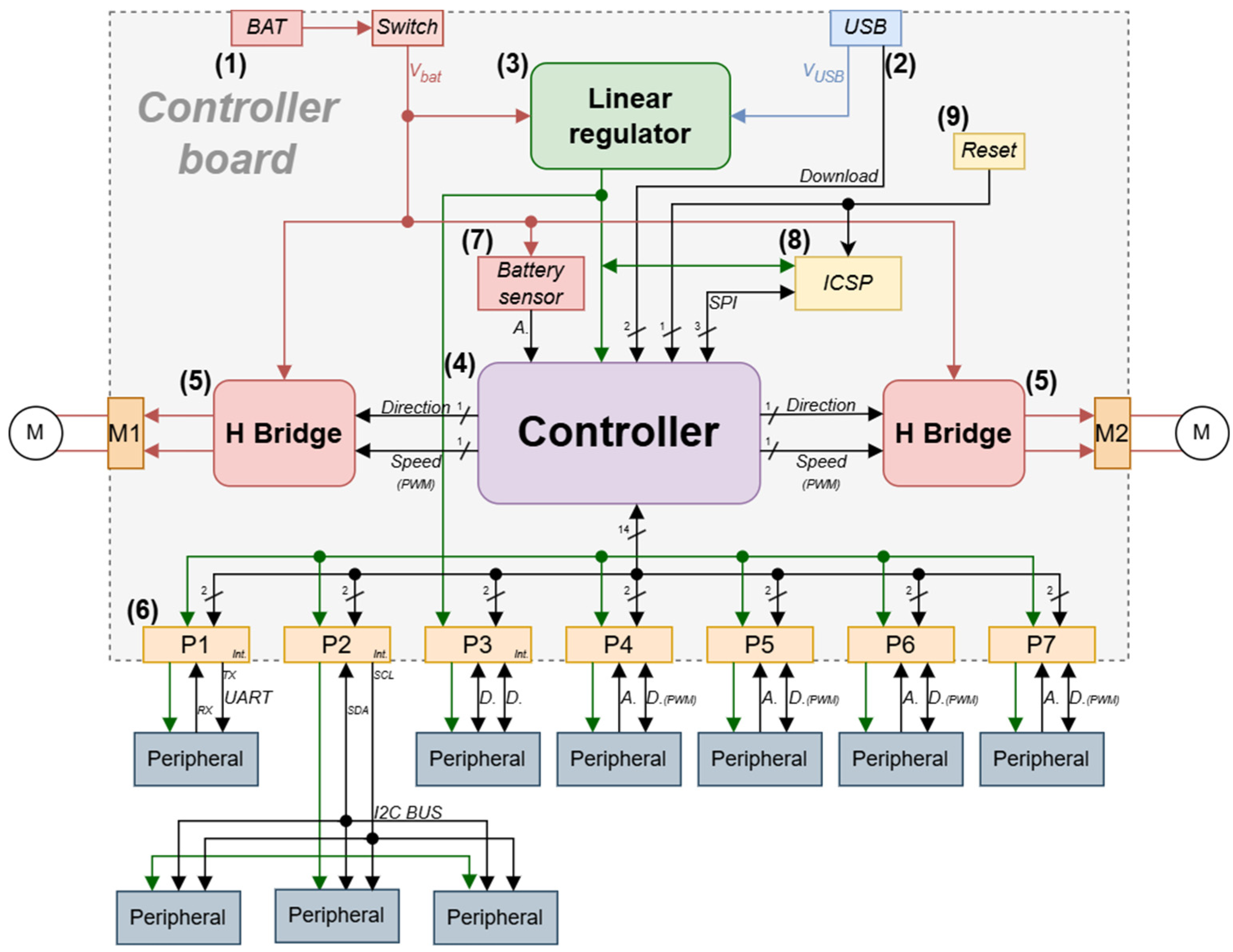
Figure 4 shows the system architecture and includes (1) a battery power entry, (2) a USB port, (3) a linear voltage regulator, (4) the microcontroller, (5) two high-performance H-bridges for motor control, and (6) seven multifunction input/output ports. It also incorporates (7) a battery sensor, (8) an ICSP (In-Circuit Serial Programming) connector for bootloader programming, and (9) a reset circuit.
All peripheral ports can be used as digital input/output signals; some of them also provide additional functions, such as UART (Universal Asynchronous Receiver-Transmitter) serial communication, an I2C (Inter-Integrated Circuit) bus, analogue inputs, or PWM outputs. This multifunctionality allows the robot configuration to be adapted to different practice profiles (training, prototyping, or competition) without modifying the main board.

4.2. Connection System

The reliability of mechanical and electrical connections is one of the key requirements defined for the platform. For this reason, EASYbot uses JST-PH connectors with a 2.0 mm pitch, a choice based on four main technical criteria:
  • Mechanical safety: The connector design incorporates a retention mechanism that prevents accidental disconnection during impacts or sudden movements.
  • Reverse polarity protection: The geometry of the connector prevents insertion in the wrong orientation, protecting the electronic components from possible damage caused by handling errors.
  • Signal distribution: Each port provides four pins that allow power signals (VCC and GND) along with analogue/digital signals or communication buses (I2C/UART).
  • Electrical capabilities: these connectors support up to 100 V and 2 A of current.
To connect the system to a developer’s computer, a micro-USB port is provided that serves as both a programming and serial communication interface and a power source during debugging and testing. This allows students to power and test sensors, low-power actuators, and control logic without the need for an external battery.

4.3. EASYbot Arduino Board V1.1

The central component of the platform is the EASYbot Arduino Board, a dedicated board that incorporates the technical and educational requirements defined above. It integrates the microcontroller, a power management system, power motor stages, and peripheral connectivity, reducing the number of external modules and associated wiring.

4.3.1. Power Supply Subsystem

Efficient power management is essential in the EASYbot platform, given the need to coexist with high motor current demands while ensuring the stability of the control electronics. The system implements a dual power supply architecture that can switch between the USB connection and an external battery (typically a 3.7 V or 7.4 V LiPo battery). This switch is transparent and gives priority to the USB power supply when the system is connected to a computer.
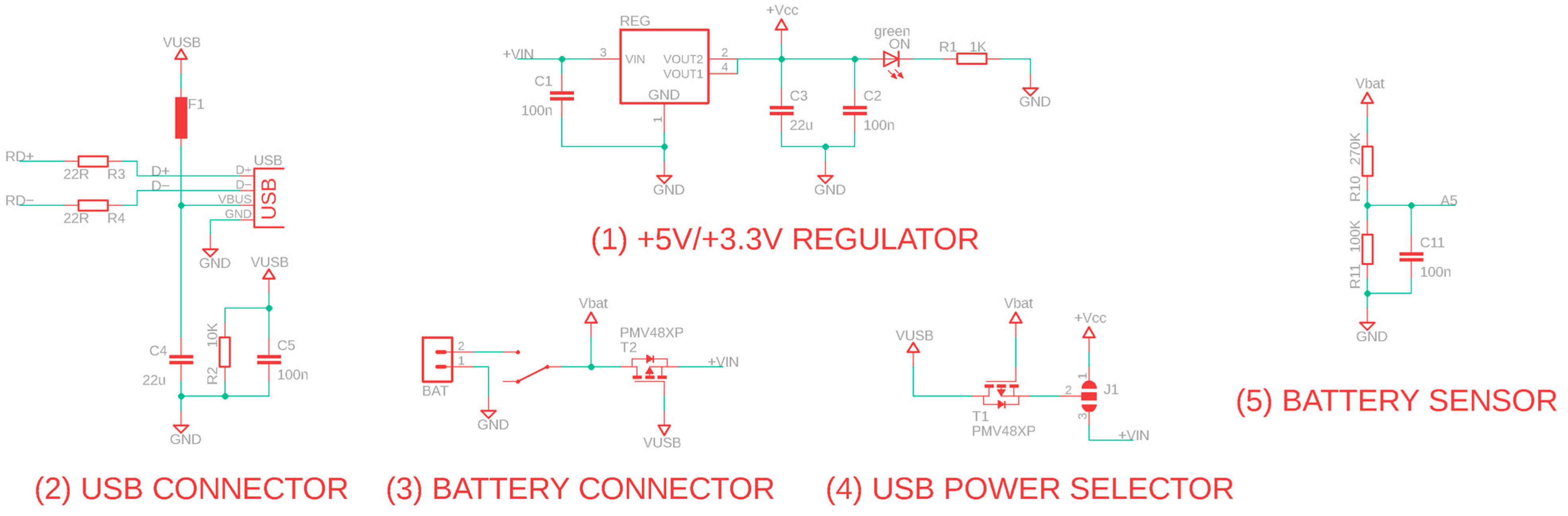
Figure 5 shows the schematic design of this subsystem, which integrates the following key elements: (1) a linear regulator that reduces the input voltage to the required logic levels and supports 3.3 V or 5 V logic voltages on the same hardware by replacing the regulator (this is essential for scalability as it allows compatibility with a wide range of peripherals without the need for external adapters), (2) a USB port for power supply, (3) the battery connector with a switch, (4) auxiliary circuits that select 3.3 V or 5 V, and (5) a voltage divider that acts as a battery level sensor (allowing software to read the battery status and prevent deep discharges).
To implement the 3.3 V and 5 V logic levels, the design utilises the ADP3338AKCZ-5-R7 and NCP1117ST50T3G low-dropout (LDO) linear regulators, respectively. These components were selected for their design compatibility (they share the SOT-223-3 package) and for a compatible auxiliary circuit, which optimises the board design. Using switch J1, the system can direct the USB input voltage to the logic signal directly or through the regulator, providing flexible adaptation to the selected operating voltage.
The values of the voltage divider resistors were strategically chosen to maximise the measurement range without compromising resolution: with 3.3 V logic, the system can monitor batteries up to 12.2 V, while in the 5 V version, the range is extended to 18.5 V. Although this measurement method is simple and has limited accuracy, it makes EASYbot independent of the specific battery type used and is suitable as a functional indicator.

4.3.2. Control and Processing Unit

The microcontroller selected for the EASYbot platform is the ATmega32U4, which is used in the Arduino Micro board. Arduino is one of the most widely used embedded systems environments in education because it provides access to a development environment and a very broad set of libraries, which reduces the barrier to entry for students with no prior experience. However, Arduino incorporates a software abstraction layer that limits direct access to certain microcontroller resources, such as timer management, for which it provides specific libraries. Nevertheless, this does not represent a real limitation because it is also possible to access the microcontroller’s registers directly. For all these reasons, Arduino has been selected over other families of microcontrollers, which, in many cases, with greater computational power, require a longer learning curve in the initial stages.
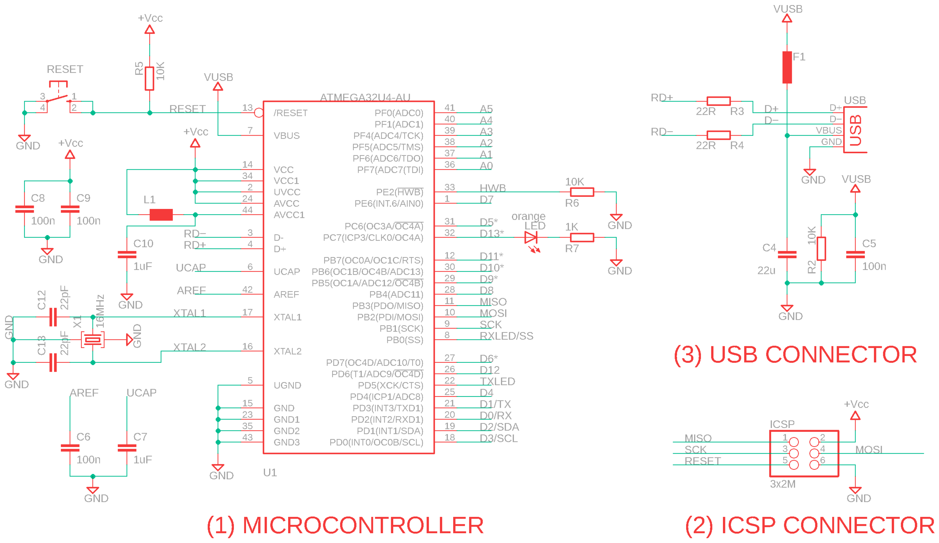
The Arduino Micro version offers an adequate balance between performance, low power consumption, and compatibility with the Arduino ecosystem, facilitating its adoption in educational contexts. In addition, the ATmega32U4 incorporates a native USB interface, eliminating the need for external converters, like the Arduino Uno version, and allowing direct communication with a computer for programming and debugging. Figure 6 shows the schematic of this control unit, based on the Arduino Micro documentation [28]. It includes: (1) the controller with its auxiliary circuitry; (2) the ICSP connector for programming the bootloader; and (3) the USB connector for communicating with the developer’s computer and downloading programmes.

4.3.3. Motor Power Stages

The EASYbot platform’s movement system is based on two high-performance H-bridges, designed to support the current demands of competition motors. To ensure efficient commutation and protect the microcontroller logic, MCP1407 gate drivers have been used. These components can supply high peak currents and provide fast MOSFET response, minimising commutation losses and reducing heating in the motor power stage.
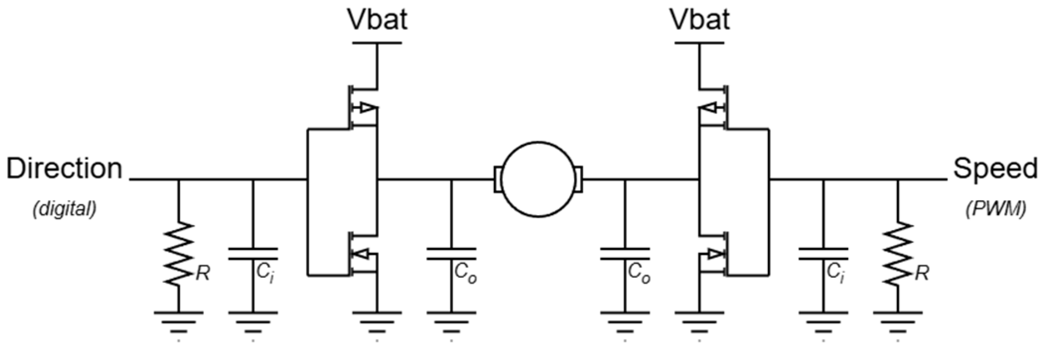
Figure 7 illustrates the conceptual design of the H-bridge, in which the control logic has been simplified to two signals per motor (direction and speed). Motor 1 uses pin D4 for direction and pin D5 for speed, while Motor 2 uses pin D12 for direction and pin D6 for speed. The design includes pull-down resistors that force the motor to stop when it is not actively being driven (e.g., during programme loading or after a reset), reducing the risk of unintended starts and improving safety during debugging and testing.
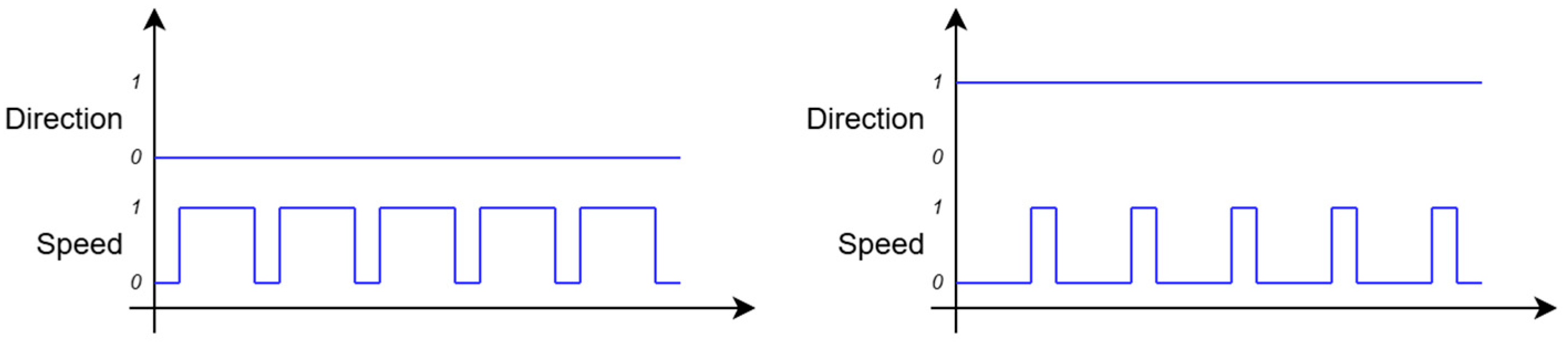
The direction signal is a digital value (‘0’ or ‘1’) that determines the direction of rotation of the motor, while the speed is a PWM signal that regulates the power supplied to the motor. In this scheme, the relationship between the two signals is not linear: when the direction signal is set to high, the PWM signal must operate with an inverted duty cycle; that is, the effective power is modulated by controlling the pulse time at the low logic level. Figure 8 illustrates how 75% of the power is obtained in both forward (left) and reverse (right) motion, avoiding discontinuities when changing direction.

4.3.4. Peripheral Ports

The EASYbot Arduino Board includes seven physical expansion ports, based on the JST-PH standard. These ports provide the primary interface for peripheral connectivity and follow a predefined pin layout. They are organised under a multifunction architecture, allowing students to configure each port according to the specific needs of the project.
Table 1 summarises the pin distribution and capabilities of these ports, illustrating the multifunctional I/O architecture and its flexibility for different robot configurations. They can be defined as follows: (1) port P1 is reserved for UART serial communication, (2) port P2 is configured to support an I2C bus, (3) ports P4–P7 allow an analogue sensor to be read on one pin and a PWM output to be generated on the other, (4) ports P1–P3 can be used with external interrupts, and (5) all ports support digital inputs/outputs.
This standardisation of the interface allows students to create prototypes quickly and safely; all ports share the same form factor and a consistent pin map, reducing connection errors (e.g., signal swapping or using an incompatible port). It also promotes a modular view of robotics, in which the incorporation of new functionalities involves the integration of a new peripheral, rather than requiring an electronic redesign. Finally, this homogeneity facilitates the reuse of peripherals in different categories of robots while maintaining the base board.

4.3.5. PCB Layout and Manufacturing Considerations

The printed circuit board (PCB) design of the EASYbot Arduino Board has been optimised to ensure electrical and mechanical robustness under real operating conditions. The placement of components follows a functional block segmentation approach, separating the control logic from the motor power stages to minimise electromagnetic interference (EMI). A critical aspect of the design is the sizing of the copper traces, especially on the lines feeding the H-bridges and the motor outputs. These have been oversized (0.6 mm wide) to support high current peaks without the risk of overheating or excessive voltage drops. In addition, large ground planes have been implemented, which not only provide a stable voltage reference but also act as passive heat sinks for the motor controllers and voltage regulators.
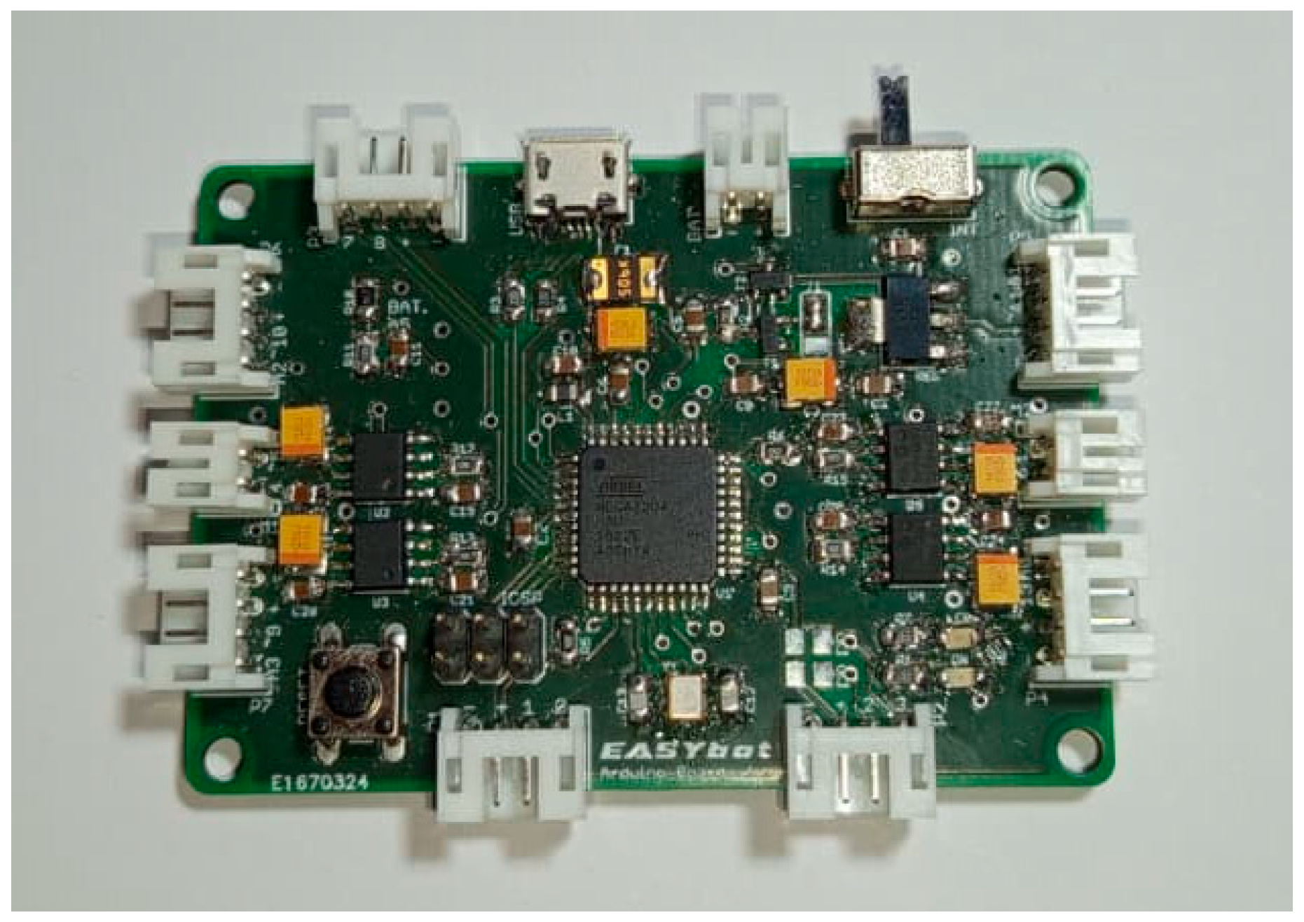
Finally, the board has been professionally manufactured with a finish that facilitates soldering and maintenance. Detailed silkscreen printing includes the identification of each pin and expansion port, helping students to identify the board’s connections without having to constantly refer to the schematic. Figure 9 shows the assembled EASYbot Arduino Board.

4.4. Peripherals and Expansion Modules

The EASYbot platform has the capacity to integrate a wide range of peripherals in a modular manner, and this approach enables the robot to evolve from a basic configuration to more complex systems. The design of these peripherals follows a principle of interoperability based on the JST-PH connection standard described in Section 4.2, so that each peripheral can be swapped or combined without modifying the rest of the system.

4.4.1. Wiring and Interconnection Systems

Wiring is one of the most critical elements in educational and competition robots because it is responsible for a large proportion of electrical failures, such as disconnections, intermittent contacts, or breakages related to extraction. For this reason, the EASYbot platform defines a standard interconnection system based on four-wire cables compatible with the JST-PH connectors on the main board, with the aim of ensuring secure, repeatable connections and a clean and well-organised peripheral layout. Three wiring configurations have been defined (with variable lengths depending on the assembly):
  • Standard 4-to-4 wiring (see Figure 10a): Includes all four cables, with JST-PH connectors at both ends. It is used when power and two signal lines (e.g., communication buses or peripherals that use both I/O pins) must be carried simultaneously.
  • Digital 4-to-3 wiring (see Figure 10b): Includes power and a single signal line, intended for digital peripherals. It uses a 4-pin JST-PH connector at the main board end and a 3-pin connector at the peripheral end.
  • Analogue 4-to-3 wiring (see Figure 10c): Includes power and a single signal line, originally intended for analogue input peripherals. The digital 4-to-3 wiring uses a 4-pin JST-PH connector towards the main board and a 3-pin connector towards the peripheral. Although designed for analogue inputs, it can also be used with digital peripherals.
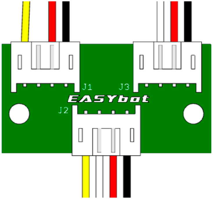
When it is necessary to connect two independent peripherals to the same port, an I/O splitter (see Figure 11) allows the port to be divided into two branches. In this case, a 4-to-3 wiring is used for each peripheral (one digital and one analogue), and a standard 4-to-4 wiring connects the splitter to the main board. This splitter is developed for scenarios where the number of peripherals exceeds the number of available ports.
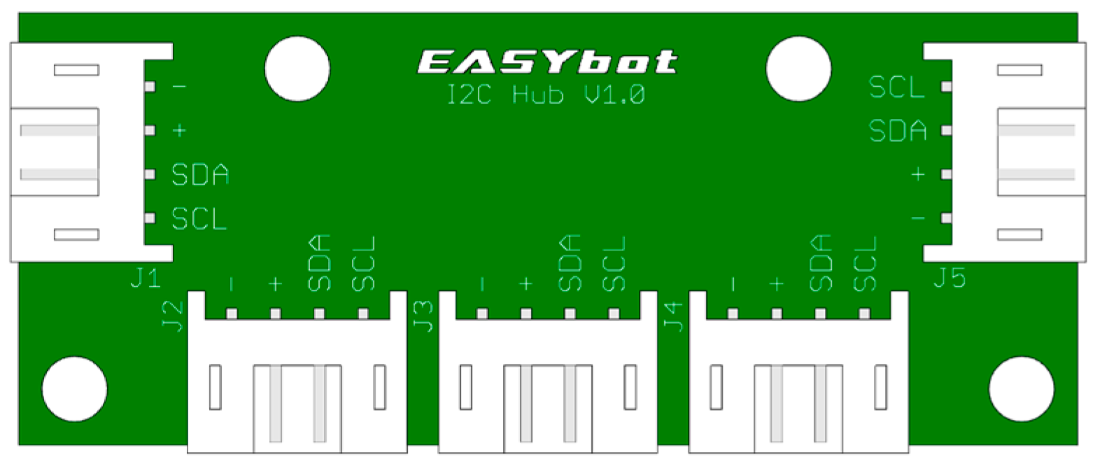
The splitter can also be used as an I2C hub, allowing two peripherals to share the same bus using standard 4-to-4 wiring. Using the same scheme, there are hubs for three or more I2C devices, such as the one shown in Figure 12. This makes it easy to expand the peripheral ecosystem when required by the project.

4.4.2. Peripheral Design Guidelines

For designing peripherals compatible with the EASYbot platform, both for new developments and the integration of commercial components, a series of principles and functional constraints is established to ensure interoperability, ease of connection, and system scalability.
Firstly, all ports on the platform incorporate power and common reference lines, including a positive power supply signal (+VCC), which can be 3.3 V or 5 V, depending on the system configuration, and a ground connection (GND), corresponding to pins 3 and 4, respectively. This standardisation ensures the electrical compatibility of all peripherals.
Each port has a maximum of two control signals (pins 1 and 2), which can be used as digital inputs or outputs. In addition, these same lines can be used for analogue signals, allowing for the use of one analogue input (pin 1) and one analogue output or PWM signal (pin 2), depending on the peripheral’s requirements.
For peripherals that use communication, specific conventions are established to ensure consistency in interconnection. For UART interfaces, the transmit signal (TX) must be connected to pin 1, while the receive signal (RX) is assigned to pin 2. Similarly, for devices based on the I2C bus, the SDL (Serial Clock Line) is connected to pin 1 and the SDA (Serial Data Line) to pin 2.
Finally, if a peripheral requires more input/output signals than are available on a single port, multiple ports on the platform must be used; this allows the system’s modularity to be maintained without compromising the simplicity of the basic design.
Additionally, the choice of wiring colours (black to GND, red to VCC, and white or yellow to signal lines) allows for a consistent map for tracking connections. The yellow wire is associated with an analogue input, the TX signal in UART communications, or the SCL line on I2C buses. And the white wire corresponds to an analogue output or PWM signal, the RX signal in UART, or the SDA line on the I2C bus. Figure 13 shows the layout of a 4-pin connector, together with a standard 4-to-4 cable.

4.4.3. Training Peripherals

To facilitate a progressive learning process, from basic exercises to more complex integrations, the EASYbot platform includes a set of training peripherals designed with the same interconnection system. These components allow the gradual introduction of key concepts such as sensor reading, PWM signal generation, communications, or interrupt management. This section describes the peripherals developed, summarises their educational purpose, and explains their integration into the platform.
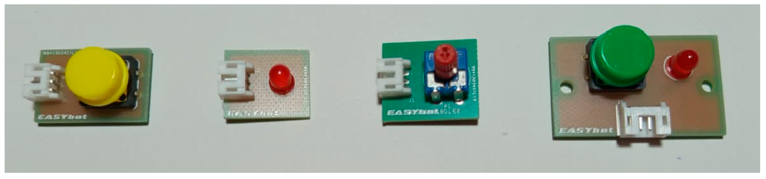
The first training peripheral is a push-button, as it is one of the simplest and most representative digital inputs for introducing digital signal reading. This peripheral is particularly useful in early training sessions to address concepts such as edge detection, software debouncing, or basic timing. The next training peripheral is an LED diode, which is used as an ON-OFF digital output or as a PWM output to regulate brightness. Like the push-button, it integrates a 3-pin JST-PH connector compatible with the digital 4-to-3 wiring, making it easy to use in training activities. The third training peripheral is an angular potentiometer, which must be connected to a port with an analogue input using the analogue 4-to-3 wiring. This peripheral allows students to read an analogue sensor and work on ADC conversion and the scaling of measured quantities.
With these three peripherals and the I/O splitter (Figure 11), various training activities can be carried out using different peripheral configurations. In addition, a fourth peripheral has been developed that combines a push-button and an LED diode within the same hardware module. Figure 14 shows these four peripherals for digital and analogue input/output training.
Motor control is fundamental in robotics projects; therefore, the platform recommends the Pololu DC micro-motors. For motor connection, the wiring uses a 2-pin JST-PH connector with no fixed polarity, so that identifying the rotation direction and its relationship to the control signals becomes part of the training itself.
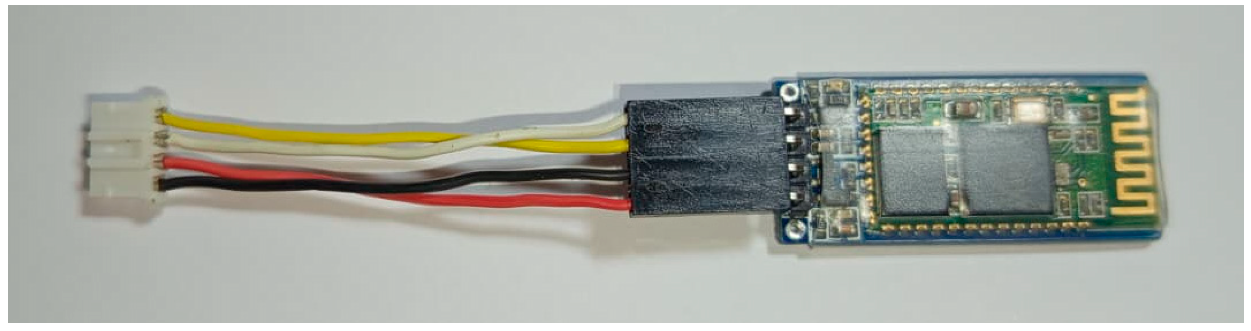
Once the training with basic digital and analogue I/O peripherals and DC motors is completed, students can work with advanced components, such as the UART serial interface and Bluetooth communication using the HC-05 module. In this case, a dedicated adapter wiring was designed (see Figure 15) because the standard 4-to-4 wiring cannot be used due to the type of connector and the pinout of the HC-05. This solution maintains the platform interconnection model while incorporating a widely used commercial module for basic remote-control practice.
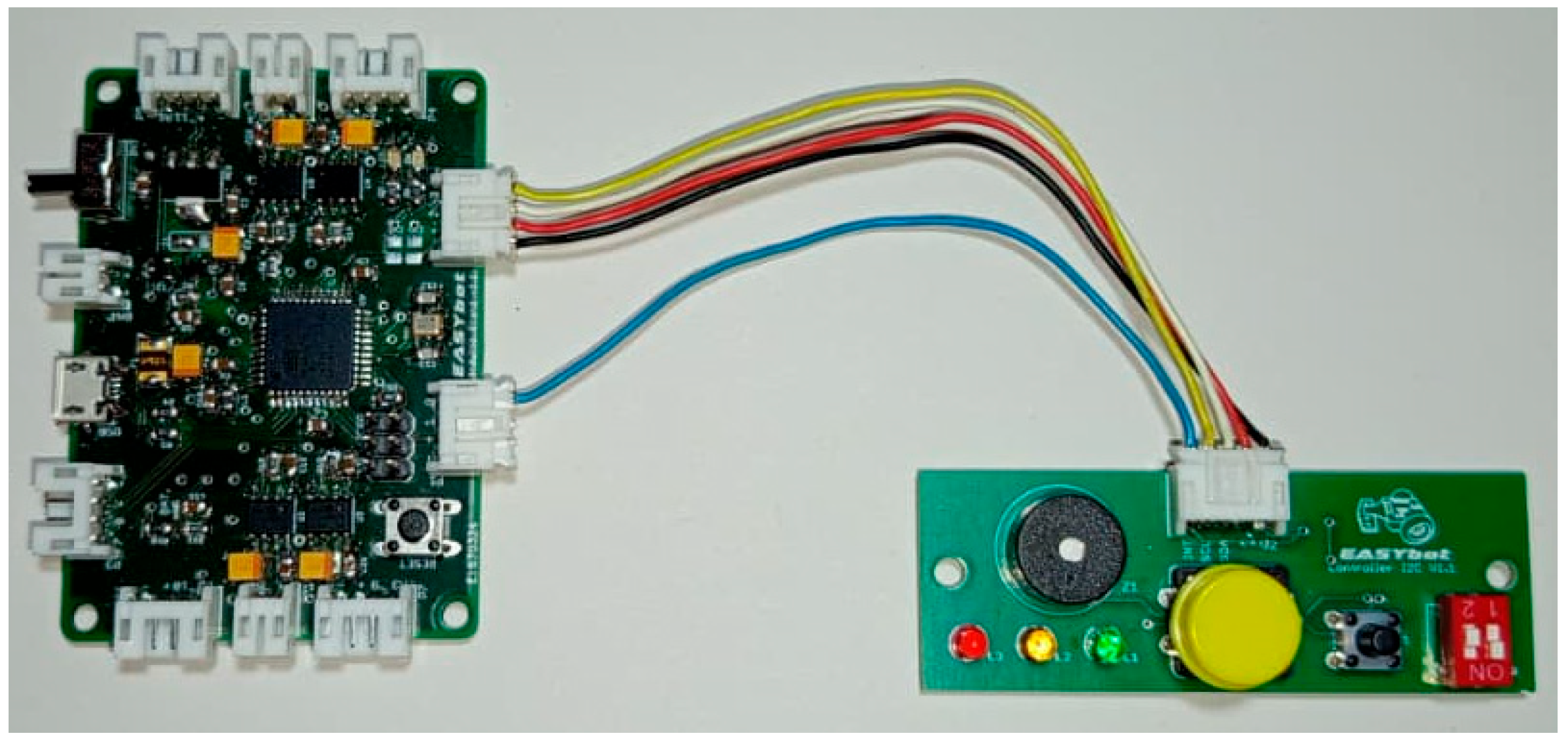
To conclude the training, the platform allows for practice with the I2C bus through a peripheral called EASYbot IO Controller. It integrates a double micro-switch, a small push-button, a large push-button, three LEDs of different colours, and a buzzer, together with the MCP23008 digital I/O expander. Figure 16 shows this peripheral, which is also designed for use in the competition robots in order to manage and configure them. In this case, it uses a fifth pin on the connector with an interrupt line, allowing the microcontroller to detect peripheral events without continuous polling and introducing students to this programming model. This additional pin must be connected to a port on the main board with interrupt capability.

4.4.4. Competition Robotics Peripherals

The four competition categories implemented with the EASYbot platform are: line-follower, tracker, mini-sumo, and maze. In each case, a different combination of peripherals is used, where some modules can be shared between categories (e.g., the EASYbot IO Controller or the HC-05 Bluetooth module), while other peripherals are specific to each category depending on the sensor requirements.
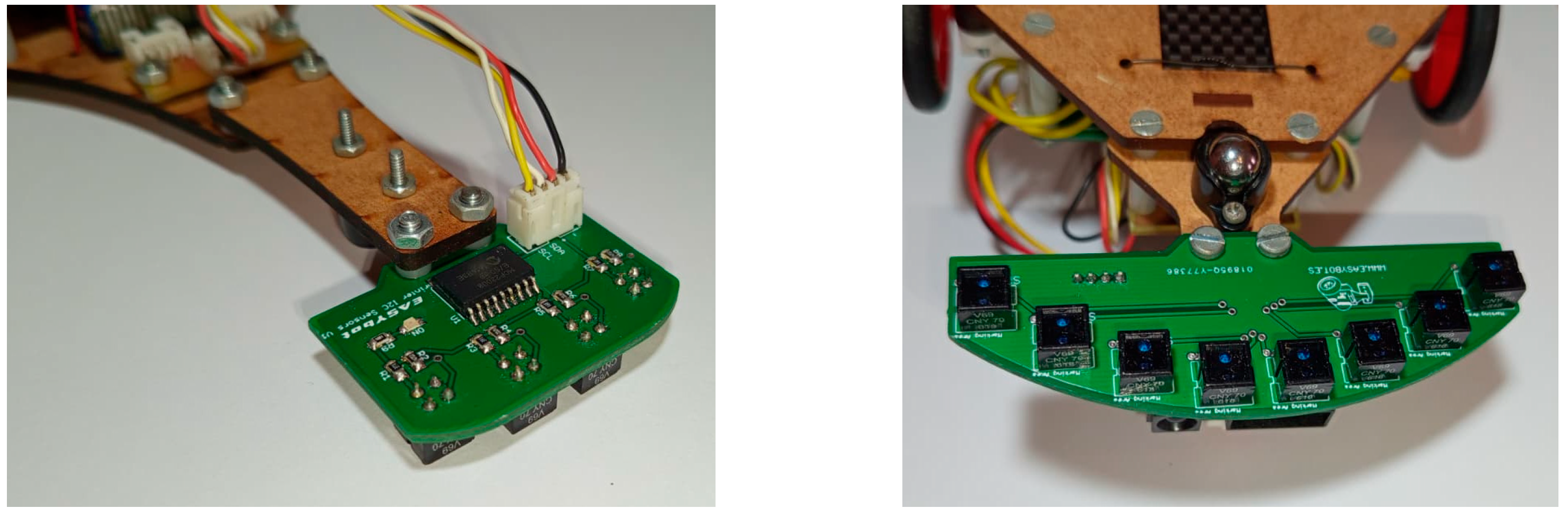
For the line-follower robot, a specific peripheral has been developed that integrates four CNY70 sensors. These sensors allow the robot to distinguish between black and white surfaces and allow it to follow the reference line on the circuit. To simplify wiring and improve scalability, this peripheral uses the MCP23008 Digital I/O Expander via the I2C bus. The tracker robot uses a version with eight CNY70 sensors, which are necessary both for line tracking and for detecting lateral markers. Figure 17 shows these two sensor peripherals integrated into the robots.
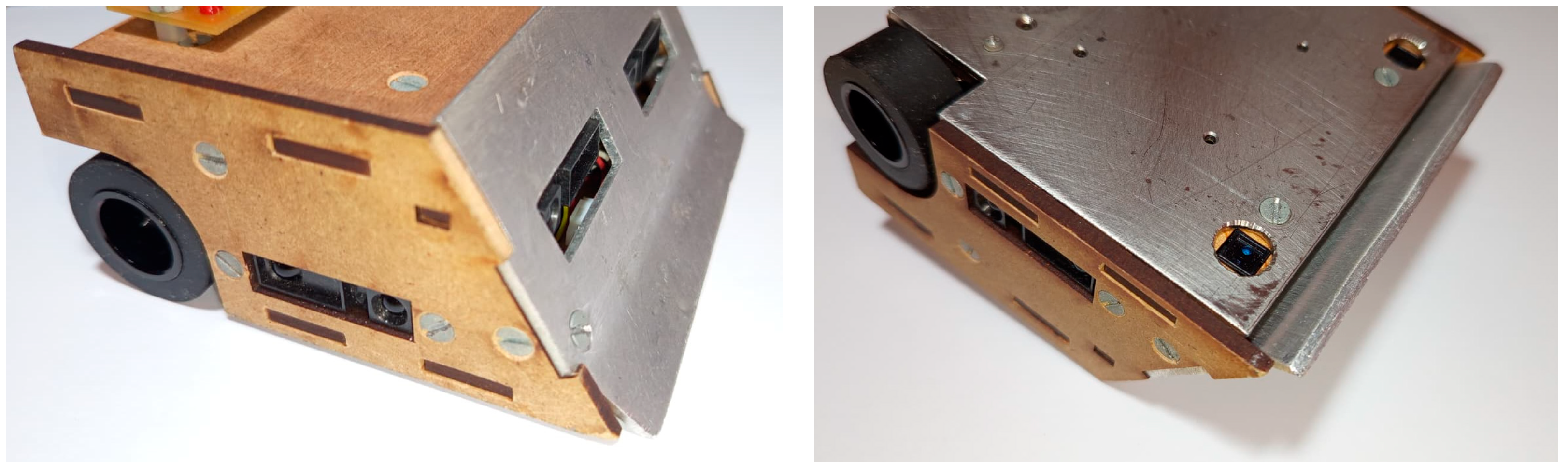
The mini-sumo robot uses SHARP infrared distance sensors to detect the opponent. In this case, the sensors themselves use 3-pin JST-PH connectors compatible with the analogue 4-to-3 wiring. This robot also uses single CNY70 sensors to detect the tatami limit. In this case, a CNY70 sensor board has been developed to facilitate its integration into the robot with a digital 4-to-3 wiring. Figure 18 shows the integration of these peripherals into the robot.
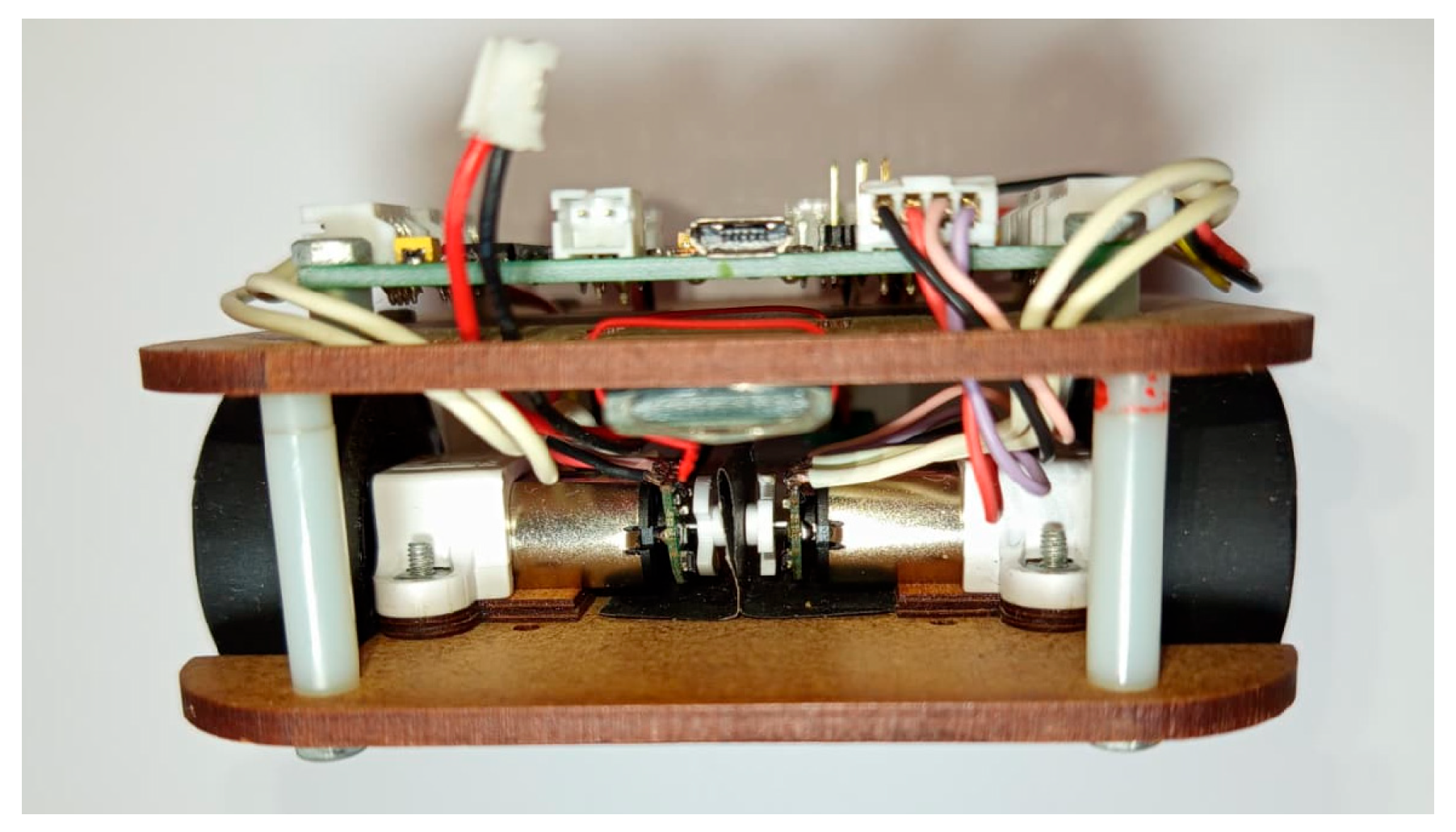
Finally, the maze category also uses infrared distance sensors: SHARP GP2Y0A51 sensors (range: from 2 to 15 cm). This sensor uses a different 3-pin connector, so it is necessary to adapt the analogue 4-to-3 wiring to make it compatible with the EASYbot platform. The use of encoders in the motors is very important in this robot, because motion precision is critical for accurate displacements and controlled turns. To this end, maze robots utilise Pololu optical or magnetic encoders integrated directly into the DC micro-motors used. Figure 19 shows the optical encoders integrated into the motors of a maze robot.

4.5. Software Design

Software development of the EASYbot platform is conceived as a central element of the overall system. Its main objective is to support a progressive learning process, from introductory exercises to more demanding control developments. To this end, the firmware is based on the Arduino ecosystem (C/C++), organised around a state-based model, and supported by auxiliary libraries that reduce initial complexity without preventing more advanced development when a project requires it.
The software is designed according to four principles: (1) modularity, which allows adding or replacing peripherals without rewriting the robot’s overall logic; (2) scalability, so that the same project can evolve from a functional prototype to an optimised version; (3) reusability, minimising software redesign when changing categories; and (4) transparency, so that students can understand what is executing and when it is executing.
These principles are in line with the educational requirements established in Section 3, with special focus on the hardware-software relationship and the gradual introduction of advanced concepts.

4.5.1. Firmware Organisation

The firmware structure follows a common pattern in the Arduino ecosystem and is divided into three blocks:
  • Setup: Initialises hardware configuration, loads the initial state, and performs basic checks. The aim of this part is to start the robot in a safe state, forcing the outputs to known conditions to prevent unintended motion.
  • Loop: Repeatedly executes reading, computing, and acting tasks. When timing is required, blocking delays can be used in early stages, and, in more advanced stages, time references based on the system clock can be introduced to improve the robot’s responsiveness.
  • Events: At a basic level, input peripherals are read through periodic polling, while at advanced levels, interrupts are introduced for the most critical peripherals.
Students can use functions and the object-oriented programming paradigm in their code, and they can also debug the robot’s behaviour via the serial port without modifying the overall structure.

4.5.2. State-Based Programming Model

At this level of education, students are still developing their structured programming skills. They often use functions primarily for code reuse rather than for structuring the overall system. Furthermore, their level of abstract thinking is still evolving, making it challenging to address complex problems as a whole. In this context, an approach such as state-based programming, called the State Pattern in [29], maintains the same functionality by structuring the code in independent states that define their behaviour locally and eliminating problematic nested “if” statements, thus favouring the maintenance and expansion of the code.
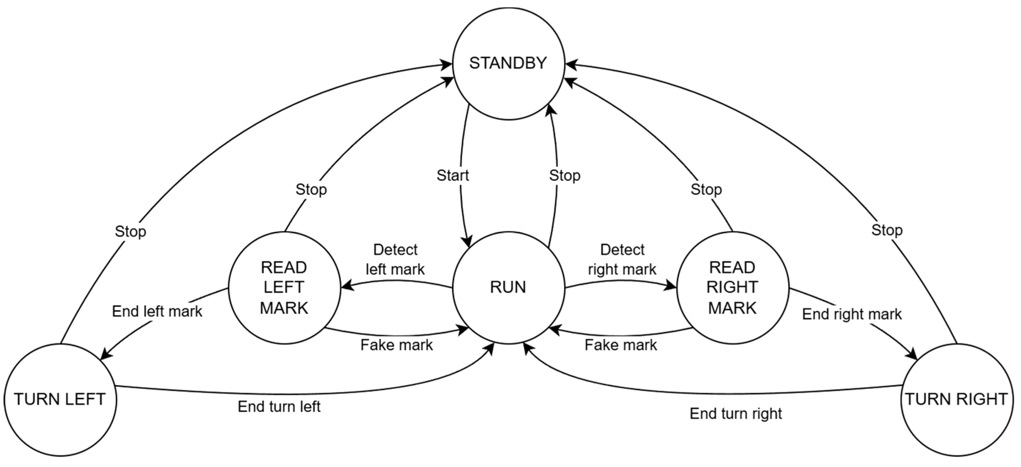
In this approach, behaviour is divided into states (e.g., stopped, tracking, attack, turn_right, etc.) and transitions defined by events or conditions (e.g., line detection, distance to opponent, elapsed time, distance travelled, etc.). Figure 20 shows an example of a state diagram for a tracker robot.
This model provides three main advantages: (1) it separates logic and control, as each state encapsulates concrete actions, facilitating debugging and maintenance; (2) it encourages reuse of states and transitions between categories; and (3) it supports scalability, since one can start with few states and simple transitions and then introduce more complex strategies without rewriting the entire system.

4.5.3. Available Libraries

The software can use auxiliary libraries that encapsulate access to the most common hardware elements of the platform. Currently, the EASYbot platform includes two dedicated libraries: one for motor control and another for the MCP23008 digital I/O expander.
The DcMotor library, https://github.com/jonathanruizdegaribay/DcMotor (accessed on 31 March 2026), allows motor control using the functional model implemented on the EASYbot platform. This library does not hide pin assignments (direction and speed), keeping the hardware-software relationship visible. Its use is recommended after initial training in which students have implemented direct motor control using digital outputs and PWM modulation.
To manage different peripherals based on the MCP23008 digital I/O expander, the MCP23008 library https://github.com/jonathanruizdegaribay/MCP23008 (accessed on 31 March 2026), simplifies the handling of these peripherals. In advanced courses, this library can be omitted to address I2C communication and its protocol at a lower level.

4.5.4. PD Control

Precise and stable movements are essential in competition robots because even small deviations in trajectory or speed can result in slower times for line-follower robots or navigation errors for maze robots. In an educational context, PID (proportional, integrate, and derivative) control is a common choice due to its popularity and the availability of well-established tuning methodologies. However, the integral term can sometimes be ineffective; for example, the line-follower robot introduces a persistent error because the circuits are usually closed and robots tend to go out in the same direction, resulting in overcorrections and oscillations. For this reason, the proposed teaching strategy involves working with proportional control first, before improving performance by incorporating the derivative term once tracking has stabilised. The PD control can be implemented using a simple equation, suitable for microcontrollers, formulated as follows:
o t = k p × e t + k d × e t e t 1
where e t is the error at the time t , e t 1 is the error at the previous time, and k p and k d are the proportional and derivative gains, respectively. The control output o t is used to adjust the motors’ base speed, as shown in the following equations:
S L = S b a s e o t
S R = S b a s e + o t
This model has two main advantages for teaching: (1) it is easy to implement and requires few computational resources, and (2) it allows the effect of each term to be visualised quickly when adjusting parameters during testing. While the control equation is simple, students have difficulties in defining and calculating the error, which depends on the type of robot and its sensor configuration.

5. Technical Validation of the Platform

The design and implementation of a robotics platform entail the integration of multiple subsystems (power supply, controller, motor power stages, interconnection, and peripherals), whose behaviour must be evaluated to ensure correct, safe, and reliable operation in both learning and competition contexts.

5.1. Electrical Verification

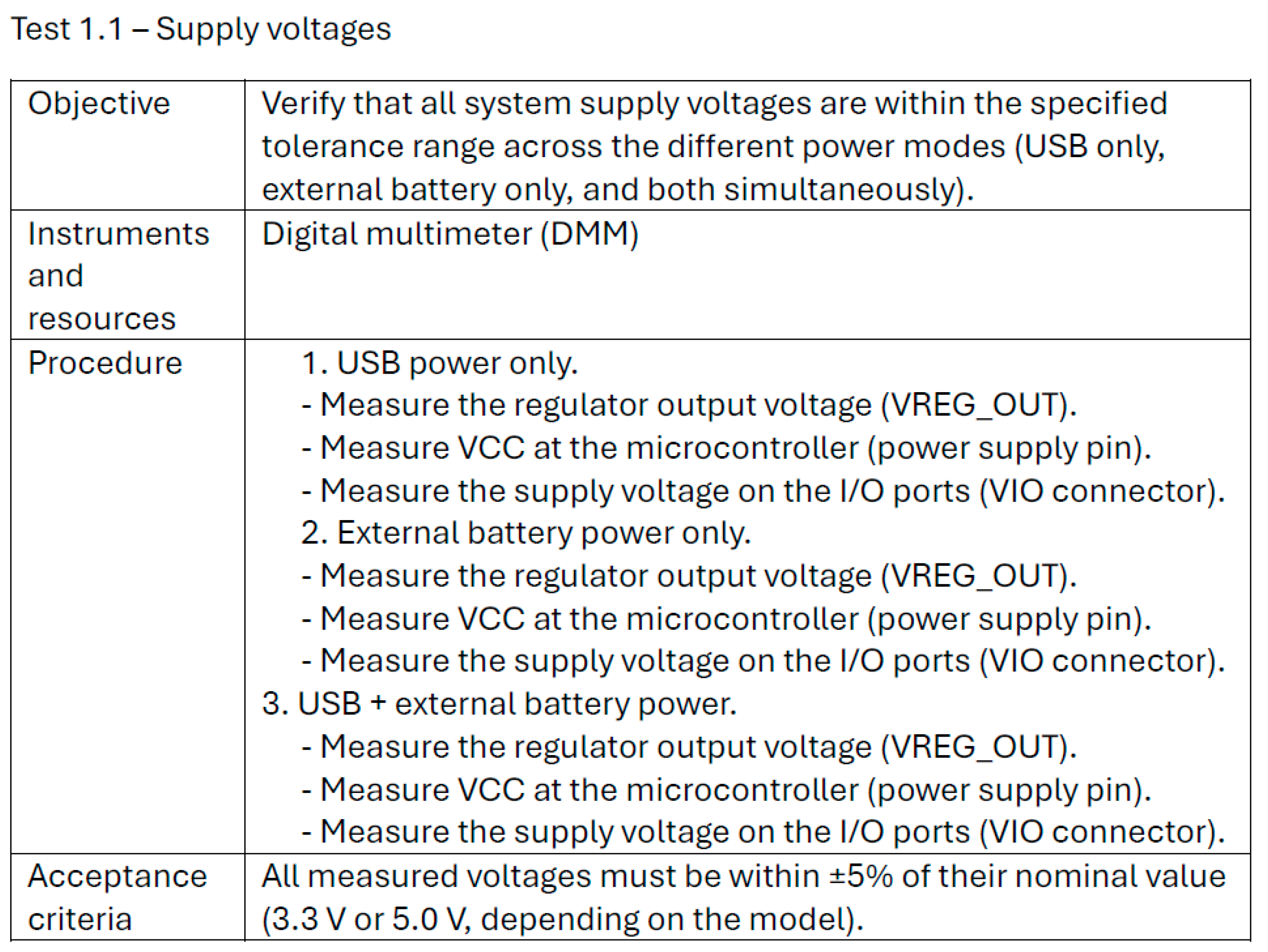
Since the initial version of the EASYbot platform, a series of tests have been conducted to verify that the subsystems function within the expected specifications and that the electrical behaviour of the entire system is consistent under real-use conditions (USB and battery supply, load variations, and motor operation). In order to ensure the reproducibility of results and facilitate the traceability between versions, all tests are defined using a uniform structure. This structure includes the objective of the test, the instruments and resources required, the procedural measures, and the acceptance criteria. Figure 21 shows the test sheet utilised to verify the voltage levels on the EASYbot Arduino Board.
The following sections examine the tests performed on the main EASYbot subsystems. The EASYbot Arduino Board incorporates all of these subsystems, and analogous tests have been defined for the remaining peripherals for technical validation purposes.

5.1.1. Power Supply Subsystem

Within the power supply subsystem, a series of tests has been defined to verify voltage stability at the main system nodes and to confirm consistent electrical behaviour under varying operating scenarios. Specifically, these tests enable the following: (1) validation of switching between USB power and an external battery, (2) verification that voltage levels remain within the expected margins, and (3) assessment of logic-rail stability when current peaks occur due to the power stages. Furthermore, a series of measurements has been obtained at representative nodes to ensure that consumption aligns with projections under operating conditions.
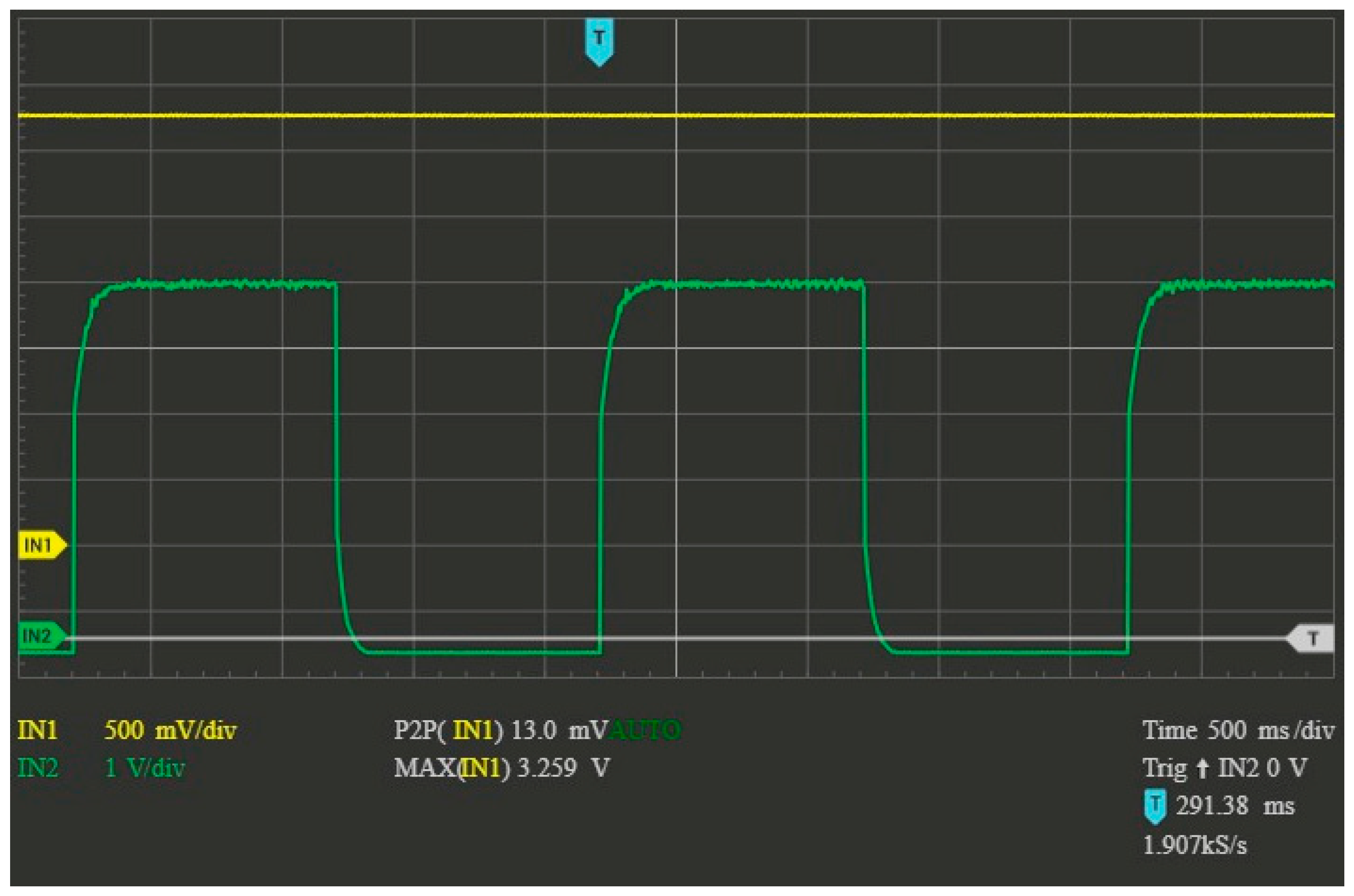
The results of the study were consistent with the expected outcomes. Figure 22, for example, shows the results of one of the tests carried out, in which the motors are activated and stopped every 1 s (green signal), and the ripple peak-to-peak of the supply voltage (yellow signal) is analysed for the 3.3 V version. As can be seen at the bottom of the graph. The ripple voltage is 0.013 volts and is not affected by the activation or deactivation of the motors.
However, a limitation has been identified in the implemented switching system: it is not able to fully isolate the USB supply from the power stages. This observation has been taken into account in the context of the platform’s use, and it has been verified that no long-term damage is caused to the USB port, the battery, or the motor power stages. However, students should be made aware of this, especially when performing debugging tests.
A final test related to the power supply concerns validating the accuracy of battery-voltage readings while also confirming that the ADC input limit is not exceeded (3.3 V or 5 V, depending on the board version).

5.1.2. Motor Power Stages

The motor power stages represent a critical subsystem of the platform, as they are responsible for managing high currents with motor startup and load fluctuations. For this reason, specific tests have been defined to verify three things: (1) correct H-bridge actuation and its response to PWM and direction signals, (2) electrical behaviour under different demand levels (e.g., start-up, sustained load, and direction changes), and (3) robustness under conditions commonly found in competitions.
The results obtained were satisfactory, thereby confirming the stability of the motor power stages and the consistency of the motor-control response. In particular, the correct behaviour of the two-signal-per-motor control model (direction and speed) was verified, as well as the absence of unintended activations during reset and firmware upload.

5.1.3. Input/Output and Communication Interfaces

The input/output and communication interfaces provide the link between the main board and the EASYbot peripheral ecosystem. Consequently, their verification is essential to ensure reproducible behaviour in training and competition scenarios. To validate the system’s correct operation, a series of tests have been defined to: (1) confirm availability and correct function assignment in the ports (digital read/write, analogue read, and PWM generation), (2) verify correct operation of the intended communication buses (UART, I2C, and SPI), and (3) ensure that the power distributed through the ports remains stable during normal system operation.
The findings indicate that the developed components show tolerance to short-circuits and reverse connections when these situations occur for brief periods. Additionally, it confirms that logic levels at the interfaces are correct in both the 3.3 V and 5 V configurations. Regarding possible interference between data lines, coupling effects were observed in analogue inputs during the execution of multiple ADC conversions across different channels. Given the absence of any discernible hardware design faults, the test was repeated on an Arduino Micro board, observing analogous results. The results suggest that the phenomenon may have its origin in the microcontroller’s ADC, specifically in its sampling and retention capacity. Students are advised to perform a discarding reading if they identify reading errors.

5.1.4. Robot Consumption

Analysing the energy consumption of competition robots is particularly important in demanding environments. Without encoders, movements tend to be based on timing or estimated power levels, which are directly dependent on battery charge. This limits the precision of motion, and variations in the supply voltage affect motor behaviour.
In a mini-sumo robot, battery management is critical because force depends on the battery’s charge level and the motor’s power, which directly influence combat performance. To obtain a preliminary autonomy estimation, a theoretical consumption analysis was carried out using three representative modes—standby, search, and attack—assigned approximate durations of 30, 50, and 40 s, respectively, resulting in an operating cycle of 120 s per combat.
The power model was built from the robot’s main subsystems: an EASYbot Arduino board; an EASYbot I/O controller; two black-and-white sensors; four infrared distance sensors; two DC motors; and an optional Bluetooth transceiver. Table 2 reports the average power consumption of each component obtained from laboratory tests for EASYbot components and DC motors (operative voltage is different from that used in documentation) and from datasheets for commercial components for the three modes and the total power consumption per mode, taking into account the number of quantities.
The robot’s average power consumption is calculated by taking the weighted sum of the power consumed in each operating mode, based on its duration, and dividing it by the total operating time.
I a v e r a g e = I i × t i t i = 30   s × 221.46   m A + 50   s × 700.19   m A + 40   s × 5180.19   m A 30   s + 50   s + 40   s = 2073.84   m A ,
Finally, the system’s autonomy can be estimated by dividing the nominal capacity of the recommended battery for the mini-sumo robot by the average power consumption.
t a u t o n o m y = C b a t I a v e r a g e = 1100   m A / h 2123.80   m A = 31.82   m i n ,
Motor power consumption clearly dominates the overall energy budget, mainly due to the attack mode in which the motors can stall, which significantly increases the current demand. Nevertheless, given that the final competition typically comprises up to three rounds, each with three combats, plus a possible one-minute tie-break combat, the total operating time is approximately 16 min and 30 s, which remains below the estimated autonomy. Furthermore, teams usually recharge the robot’s battery between combats using chargers, enabling partial recovery, and they can also replace the battery, if necessary, although this is uncommon.

5.2. Functional Tests

To date, platform assembly has been carried out manually. Consequently, a functional-test protocol has been established to verify the correct operation of each unit before its use with students. The objective of this protocol is twofold: (1) to facilitate the early detection of defects in assembly or soldering and (2) to ensure the consistent operation of critical subsystems (power supply, programming, reset, motor power stages, and I/O ports), thereby reducing incidents during training sessions.
Functional tests are structured to be executed in an incremental manner, with each successive step in the verification sequence serving to verify the preceding steps. For instance, in the case of the EASYbot Arduino Board, the process starts with microcontroller programming, followed by verification of the I/O ports, the motor power stages, and the battery sensor. In all components, they are not used with students until they have passed all of their functional tests, ensuring a minimum reliability threshold in educational environments. All test programmes and acceptance criteria are maintained under version control.

6. Discussion

The initial operational version of the EASYbot Arduino Board was released on 3 March 2015. Preliminary versions of the platform had been utilised prior to the specified date in competition robots developed by the teaching team and in several final-year projects related to robotics, both competition-oriented and general. The objective of this utilisation was to validate the design feasibility and consolidate a first stable version of the platform.
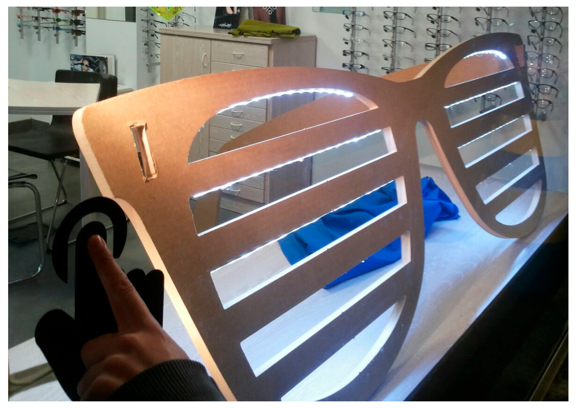
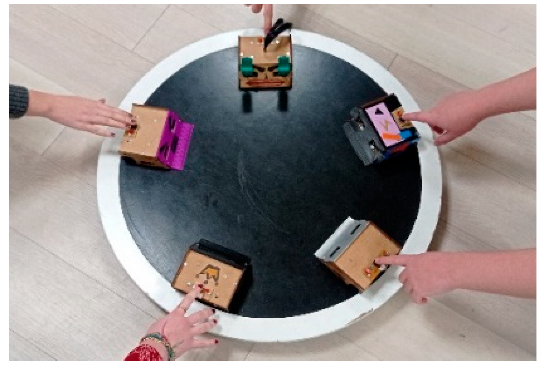
During the 2015–2016 academic year, the teaching team of the Industrial Design Engineering degree programme initiated an educational project focused on interactive shop windows. The students had limited knowledge in the domain of electronics, and their task was to design and implement a complete embedded system. The EASYbot platform was selected as the hardware base for this project because it allowed students to focus on physical design and interactive programming. This experience served as a test in a scenario that differed from the original competition-oriented objective, thereby confirming the flexibility of the platform to integrate other sensors, actuators, and lighting elements, as well as its feasibility in a real installation. Figure 23 shows an example of interactive shop windows at an optician, where the aim was to attract customers’ attention by enabling them to interact with the lights built into the frames of the glasses.
The project was implemented for two years, and in the 2016–2017 academic year, it was replaced by the first edition of the ER Competition Project in the Industrial Design Engineering degree programme. In this inaugural edition, students built a line-follower robot as a training project, and subsequently, each student team developed a tracker or a mini-sumo robot.
During the 2018–2019 academic year, the educational robotic competition project was transferred into the Digital Industry degree programme, within the Digital Electronics subject, adding the maze category. This evolution allowed the expansion of the set of challenges and increased the technical level by introducing requirements for greater precision and control. The project’s second iteration remained active until the 2024–2025 academic year; Figure 24 shows the exhibition match in the mini-sumo category.
Furthermore, the platform has been adapted on occasion for use in other teaching contexts. For instance, during the 2023–2024 academic year, an intensive version was implemented, spanning several weeks and incorporating the line-follower and mini-sumo categories. This iteration was offered within the Industrial Design Engineering degree programme again.
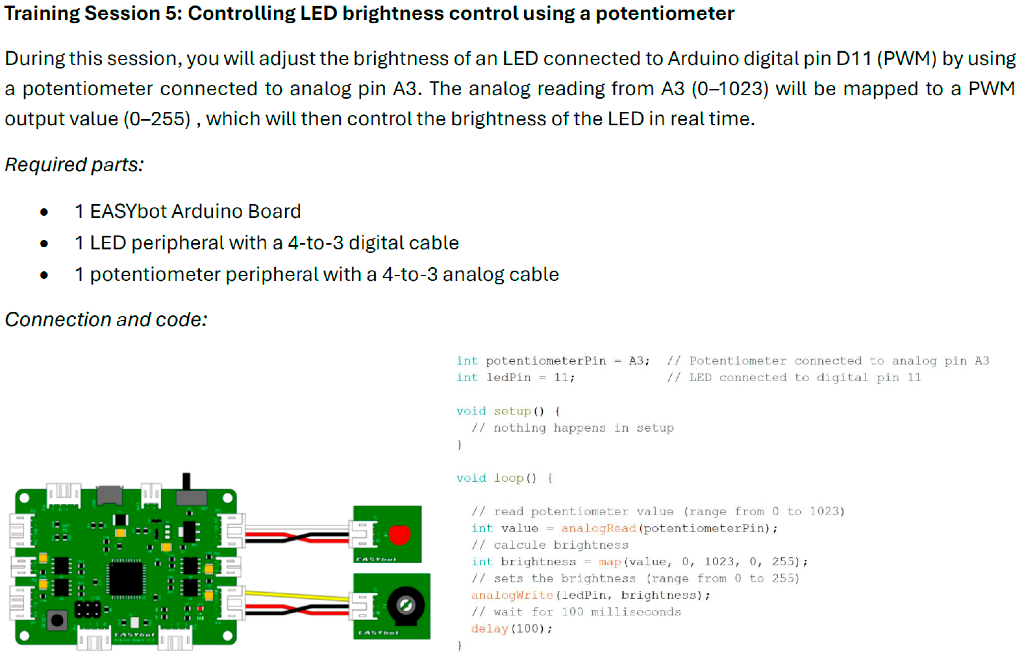
Across all these experiences, the training phase has been particularly relevant. It is developed through experimental laboratory sessions that address different aspects of the platform and the project. Figure 25 shows an example of the worksheet utilised by students to interpret an analogue sensor and to operate a PWM peripheral.
In this training, students must work with analogue inputs, which were covered in previous training with regard to voltage reading from potentiometers, and analogue outputs, which are a new concept. To achieve this, they must assemble the hardware shown in the training worksheet and validate that the proposed code is functioning correctly. The teacher can then ask questions to check understanding or request modifications to the software, such as programming the LED diode to light up in reverse proportion to the potentiometer value or asking the students to activate the LED diode when a certain threshold is exceeded.

6.1. Adoption and Usability

Since the 2018–2019 academic year, usability has been assessed through student surveys, with a quantitative valuation and an open question overall rating of the EASYbot platform. The feedback was generally positive. In the 2023–2025 period, three specific indicators were defined related to the usability: (1) ease of learning, (2) perceived reliability, and (3) documentation quality; and another one about the recommended use of the project in other courses to evaluate the Technology Acceptance Model (TAM). Table 3 summarises the results obtained from the surveys conducted over the course of the past three editions of the ER project. Two of these surveys were incorporated into the Digital Industry Degree, while the other one was incorporated into the Industrial Design Engineering degree programme.
The results of the usability survey (scale 1–5) are consistent with the TAM. The perceived ease of use (PEOU) is reflected in ease of learning (mean 3.85). Perceived usefulness (PU) is supported by perceived reliability (3.93) and documentation quality (4.04), indicating that the platform is perceived as reliable and well-documented to achieve the project’s objectives. The behavioral intention (BI) is evident in the use recommended (average 4.74), showing a high interest in recommending it. Finally, actual use (AU) is confirmed by sustained use of EASYbot in multiple ER project editions and its application in other teaching environments, which reinforces effective adoption beyond declared perception.
In the short project of Industrial Design Engineering, where students receive more guidance and the technical complexity is lower, ratings tend to be higher, in contrast to Digital Industry, where greater autonomy is necessary to understand the platform. This outcome reflects an anticipated pedagogical trade-off between ease of learning and technical depth. Nevertheless, students recommend the project, so although the difficulty is greater, they perceive that the effort is worthwhile.
The present study focuses on the design and validation of the EASYbot platform, as well as its technical and adoption validation. A more specific evaluation of educational impact has been previously addressed in works by the same teaching team. Ref. [30] shows the implementation of the five editions of the ER project under a project-based methodology, with more than 100 students and 30 robots developed, with 75% of them participating in the final competition. Additionally, improvements in the students’ perception of key knowledge areas such as programming (2.34 → 7.03 out of 10) and debugging techniques (1.26 → 5.95) before and after the project are reported. Meanwhile, the learning and motivation outcomes are reported in [31]. Of the 24 students in the Industrial Design Engineering Project, the surveys (1–5) show a significant contribution to understanding technical (4.76) and programming (4.62) concepts, as well as an increase in motivation from the beginning to the end of the project (4.32 → 4.65), despite motivation already being high at the start.

6.2. Platform Limitations and Updates

Despite its compact design, several constraints have been identified through real-use testing, primarily associated with mechanical robustness and extreme operating conditions. In version 0.4.c, the USB connector exhibited inadequate mechanical reliability and was prone to damage after extended use. This caused the 2016 update, wherein it was replaced by a connector with enhanced mechanical retention. Furthermore, students’ propensity to pull on the cable rather than the connector has resulted in recurrent cable breakages, particularly on the battery connection, which carries an associated risk of short-circuiting. In an effort to mitigate the issue, version 1.1 incorporated an external-battery cutoff switch that was designed to reduce connect/disconnect cycles. Finally, in mini-sumo robots, progressive degradation of the MCP1407 gate drivers has been observed, associated with prolonged motor blocks and high currents. This issue has been addressed in version 1.1, which incorporates new decoupling capacitors in H-bridges to mitigate the voltage peaks generated when the motors are blocked. The evolution of the hardware mentioned is shown in Table 4.
The platform architecture enables mitigations that preserve versatility in both educational and competitive settings.
  • The architecture is designed to directly support the control of two DC motors. Categories requiring higher traction or multi-motor configurations may necessitate the use of external drivers. These can be integrated in a transparent manner through the I2C bus or via digital and PWM outputs.
  • The base board contains seven physical I/O ports. In cases where projects have higher sensing requirements, splitters can be utilised to connect two peripherals to the same port. Alternatively, I2C-controlled expanders can be employed, thereby facilitating peripheral integration without the need for modifying the main board.
  • The battery level sensor, based on a voltage divider, has low precision. For competitions that require critical autonomy management, it will be necessary to use an external charge metre that, connected by I2C or to an analogue input, provides more accurate data on consumption and the remaining capacity of the external battery.

6.3. Advantages over Closed- and Open-Source Platforms

Table 5 provides a comparison of the EASYbot platform with other robotics platforms, including commercial and open robotic platforms. The qualitative levels (Low, Medium, or High) are defined based on the following criteria:
  • Technical level: The degree to which low-level hardware resources are accessible (e.g., direct control of PWM, ADC, and communication protocols).
  • Learning curve: The estimated time and complexity required for students with no prior experience to achieve basic functionality.
  • Scalability: The ability to extend the system with additional functionalities without redesigning the core architecture.
  • Reusability: The extent to which hardware and software components can be reused across different robot categories.
  • Competition suitability: Capability to meet performance and robustness requirements in competitive environments.
  • Educational approach: The extent to which the approach aligns with structured pedagogical models and progressive learning.
A comparison of the EASYbot platform with closed commercial kits reveals that it enables greater technical depth by providing access to both the hardware and the programming model. This feature avoids layers of abstraction that limit understanding of the hardware–software relationship. The incorporation of power management, motor power stages, and multifunction ports promotes practices that are in alignment with engineering workflows. While the learning curve is steeper, it is structured in a progressive way, so this is not an issue.
In comparison with generic open-source solutions that rely on external modules, the platform offers a common baseline architecture and a standardised interconnection system, improving the scalability and reusability of hardware and software. Defining educational criteria in the design of the platform and its progressive learning improves the educational approach of an open platform.
Additionally, the modular design and plug-and-play system facilitate learning by enabling the teacher to focus on the specific technical competencies of interest. For example, adding a hardware module is simple from an electronic point of view, while the focus is on programming the management of the module. Conversely, if the focus is more electronic, for example, developing a new peripheral, software functions can be reused if the same connection scheme defined in the platform is maintained. In the experiences analysed in this article, the technical skills focus on the integration of embedded systems and their programming in the Digital Industry project. In the Industrial Design Engineering project, however, the skills worked on are solely related to programming, and the same robot is used for different purposes.

7. Conclusions and Future Work

The present article presents the design and validation of EASYbot, an open, scalable, and modular platform aimed at ER and use in university-level competitions. The primary contribution of this work is the definition of an architecture that integrates power management, control, and motor power stages, in conjunction with an interconnection standard that facilitates plug-and-play peripheral integration and fosters the reusability of hardware and software across diverse robot categories.
The technical validation process has demonstrated that the platform exhibits stable operation under typical conditions of use and demonstrates reasonable tolerance to connection errors. Furthermore, compatibility of logic levels has been verified in both 3.3 V and 5 V configurations, thereby expanding the range of supported peripherals. Incidents associated with the handling of cabling and connectors have been observed during the ER project development. Furthermore, under extreme conditions, typical of the mini-sumo robot, progressive degradation has been detected in elements of the motor power stages.
The adoption results, validated using the TAM, confirm a high perceived usefulness and a recommendation intention of 4.74/5 from the students. In contexts that demand greater technical autonomy from students, the perceived ease of learning tends to decrease, confirming that the initial friction is reduced without sacrificing the technical depth.
To date, all platform documentation and project development have been carried out privately, in Spanish, in the Faculty of Engineering at the University of Deusto. The teaching team is currently working on the publication of the EASYbot platform design and implementation and its corresponding documentation. This initiative is being undertaken under the provisions of a GPL licence and will be available in both Spanish and English. The dissemination of these materials will be facilitated through a new repository on GitHub (https://github.com/) and via a new web page. The objective is to ensure the replicability of the EASYbot platform by other teaching teams in new academic contexts. In the case of non-technical teachers, training in the use of Arduino would be necessary, and the platform would be limited to developing the current categories of robots. However, if the teacher has technical knowledge, they could develop new categories by integrating or implementing new peripherals. In terms of skills, given the versatility of the platform, it could work on skills from different technical areas, such as mechanics or the development of intelligent algorithms.
The teaching team is contemplating the following future lines of work: (1) validating the H-bridges update in version 1.1 under intensive use, (2) providing support for other microcontrollers with a more professional character within the EASYbot platform, while maintaining compatibility with the current peripheral ecosystem and following the same technical validation strategy with minor adjustments, (3) analysing other competition categories and kinematic configurations, such as obstacle races in changing environments where precise frontal detection and evasion algorithms are required, or “capture the flag” where a robot must search for the opposite robot’s base and “steal” an element before returning to its own base, and (4) exploring the adaptation of the competition ER project to secondary education. The general principles of modular design and iterative validation could inspire the expansion of the platform to new categories in the future, such as remote-controlled or semi-autonomous robots [40].

Author Contributions

Conceptualization, J.R.-d.-G.; methodology, J.R.-d.-G.; design, J.R.-d.-G.; validation, J.R.-d.-G.; formal writing, J.R.-d.-G.; supervision, P.G. and S.R.-Y. All authors have read and agreed to the published version of the manuscript.

Funding

This research received no external funding.

Institutional Review Board Statement

Not applicable.

Informed Consent Statement

Informed consent was obtained from all subjects involved in the study.

Data Availability Statement

The platform design, schematics, libraries, and documentation will be available in the EASYbot repository at https://github.com/EASYbot-platform/ (accessed on 31 March 2026).and via the project portal at https://www.easybotplatform.com (accessed on 31 March 2026).

Acknowledgments

We use DeepL Translator (https://www.deepl.com/en/translator, accessed on 4 April 2026) to revise English grammatical.

Conflicts of Interest

The authors declare no conflicts of interest.

References

  1. Evripidou, S.; Georgiou, K.; Doitsidis, L.; Amanatiadis, A.A.; Zinonos, Z.; Chatzichristofis, S.A. Educational Robotics: Platforms, Competitions and Expected Learning Outcomes. IEEE Access 2020, 8, 219534–219562. [Google Scholar] [CrossRef]
  2. Valls Pou, A.; Canaleta, X.; Fonseca, D. Computational Thinking and Educational Robotics Integrated into Project-Based Learning. Sensors 2022, 22, 3746. [Google Scholar] [CrossRef] [PubMed]
  3. Coufal, P. Project-Based STEM Learning Using Educational Robotics as the Development of Student Problem-Solving Competence. Mathematics 2022, 10, 4618. [Google Scholar] [CrossRef]
  4. Lancheros-Cuesta, D.; Fabregat, R. Educational Robotics Intervention in the Motivation of Students. IEEE Rev. Iberoam. Tecnol. Aprendiz. 2022, 17, 131–139. [Google Scholar] [CrossRef]
  5. Rojas, E.M.; Valencia-Arias, A.; Vásquez Coronado, M.H.; Barandiarán Gamarra, J.M.; Agudelo-Ceballos, E.; Benjumea-Arias, M.L.; Vega Mori, L. Educational Robotics for Primary Education: An Analysis of Research Trends. Eurasia J. Math. Sci. Technol. Educ. 2025, 21, em2602. [Google Scholar] [CrossRef]
  6. Sapounidis, T.; Tselegkaridis, S.; Stamovlasis, D. Educational Robotics and STEM in Primary Education: A Review and a Meta-Analysis. J. Res. Technol. Educ. 2024, 56, 462–476. [Google Scholar] [CrossRef]
  7. Ouyang, F.; Xu, W. The Effects of Educational Robotics in STEM Education: A Multilevel Meta-Analysis. Int. J. STEM Educ. 2024, 11, 7. [Google Scholar] [CrossRef]
  8. Wang, K.; Sang, G.-Y.; Huang, L.-Z.; Li, S.-H.; Guo, J.-W. The Effectiveness of Educational Robots in Improving Learning Outcomes: A Meta-Analysis. Sustainability 2023, 15, 4637. [Google Scholar] [CrossRef]
  9. Bano, S.; Atif, K.; Mehdi, S.A. Systematic Review: Potential Effectiveness of Educational Robotics for 21st Century Skills Development in Young Learners. Educ. Inf. Technol. 2024, 29, 11135–11153. [Google Scholar] [CrossRef]
  10. Chew, M.T.; Demidenko, S.; Messom, C.; Sen Gupta, G. Robotics Competitions in Engineering Education. In Proceedings of the 4th International Conference on Autonomous Robots and Agents (ICARA 2009), Wellington, New Zealand, 10–12 February 2009; pp. 624–627. [Google Scholar] [CrossRef]
  11. Rocker Yoek, S.; Shwartz Asher, D.; Schohet, M.; Dori, Y.J. The Effect of the FIRST Robotics Program on Its Graduates. Robotics 2020, 9, 84. [Google Scholar] [CrossRef]
  12. Abas, P.E. Learning to Engineer: Integrating Robotics-Centred Project-Based Learning in Early Undergraduate Education. Educ. Sci. 2026, 16, 105. [Google Scholar] [CrossRef]
  13. Márquez-Sánchez, C.; Sandoval-Gutiérrez, J.; Martínez-Vázquez, D.L. Construction of an Educational Prototype of a Differential Wheeled Mobile Robot. Hardware 2026, 4, 2. [Google Scholar] [CrossRef]
  14. Szilágyi, S.; Körei, A.; Vaičiulytė, I. Teaching and Learning Trochoid Curves: The Importance of LEGO® Drawing Robots and Educational Robotics in Tertiary Mathematics Education. Educ. Sci. 2025, 15, 1472. [Google Scholar] [CrossRef]
  15. Alimisis, D. Educational Robotics: Open Questions and New Challenges. Themes Sci. Technol. Educ. 2013, 6, 63–71. [Google Scholar]
  16. Darmawansah, D.; Hwang, G.J.; Chen, M.R.A.; Liang, J.C. Trends and Research Foci of Robotics-Based STEM Education: A Systematic Review from Diverse Angles Based on the Technology-Based Learning Model. Int. J. STEM Educ. 2023, 10, 12. [Google Scholar] [CrossRef]
  17. Ribeiro, A.F.; Lopes, G. Learning Robotics: A Review. Curr. Robot. Rep. 2020, 1, 1–11. [Google Scholar] [CrossRef]
  18. Evripidou, S.; Doitsidis, L.; Tsinarakis, G.; Zinonos, Z.; Chatzichristofis, S.A. Selecting a Robotic Platform for Education. In Proceedings of the IEEE International Conference on Consumer Electronics (ICCE 2022), Las Vegas, NV, USA, 7–9 January 2022; pp. 1–6. [Google Scholar] [CrossRef]
  19. Kalaitzidou, M.; Pachidis, T.P. Recent Robots in STEAM Education. Educ. Sci. 2023, 13, 272. [Google Scholar] [CrossRef]
  20. Attila, K.; Szilvia, S. From Scratch to Python—Lego Robots as Motivational Tools for Coding. Multidiszcip. Tudományok 2022, 12, 247–255. [Google Scholar] [CrossRef]
  21. Seralidou, E.; Douligeris, C. Investigating the Transition from Block-Based to Text-Based Programming Techniques in Secondary Education in Greece. Eur. J. Eng. Technol. Res. 2022, 21–27. [Google Scholar] [CrossRef]
  22. Vrochidou, E.; Manios, M.; Papakostas, G.A.; Aitsidis, C.N.; Panagiotopoulos, F. Open-Source Robotics: Investigation on Existing Platforms and Their Application in Education. In Proceedings of the 26th International Conference on Software, Telecommunications and Computer Networks (SoftCOM 2018), Split, Croatia, 13–15 September 2018; pp. 1–6. [Google Scholar] [CrossRef]
  23. Weeraratne, A.; Subasinghage, K. Comparison of Open-Source Robotics Platforms for Undergraduate Education. In Proceedings of the International Research Conference on Smart Computing and Systems Engineering (SCSE 2024), Colombo, Sri Lanka, 4 April 2024; pp. 1–5. [Google Scholar] [CrossRef]
  24. Williams, R.; Safinah, A.; Alcantara, R.; Burghleh, T.; Alghowinem, S.; Breazeal, C. Doodlebot: An Educational Robot for Creativity and AI Literacy. In Proceedings of the ACM/IEEE International Conference on Human-Robot Interaction (HRI ’24), Boulder, CO, USA, 11–15 March 2024; pp. 772–780. [Google Scholar] [CrossRef]
  25. El-Fakdi, A.; Cufí, X. An Innovative Low Cost Educational Underwater Robotics Platform for Promoting Engineering Interest among Secondary School Students. Electronics 2022, 11, 373. [Google Scholar] [CrossRef]
  26. Chronis, C.; Varlamis, I. FOSSBot: An Open Source and Open Design Educational Robot. Electronics 2022, 11, 2606. [Google Scholar] [CrossRef]
  27. Quigley, M.; Gerkey, B.; Conley, K.; Faust, J.; Foote, T.; Leibs, J.; Berger, E.; Wheeler, R.; Ng, A. ROS: An Open-Source Robot Operating System. In Proceedings of the ICRA Workshop on Open Source Software, Kobe, Japan, 12–17 May 2009; p. 5. [Google Scholar]
  28. Micro|Arduino Documentation. Available online: https://docs.arduino.cc/hardware/micro/ (accessed on 31 March 2026).
  29. Freeman, E.; Robson, E. Head First Design Patterns, 2nd ed.; O’Reilly Media, Inc.: Sebastopol, CA, USA, 2020; pp. 385–428. [Google Scholar]
  30. Ruiz-de-Garibay, J.; Garaizar, P.; Almeida, A. The Integration of Project-Based Learning in Educational Robotics: Exploring Competition Robots Using the EASYbot Platform. In Proceedings of the International Conference on Technological Ecosystems for Enhancing Multiculturality (TEEM 2023), Bragança, Portugal, 25–27 October 2023; pp. 514–523. [Google Scholar] [CrossRef]
  31. Ruiz-de-Garibay, J.; Romero-Yesa, S.; Garaizar, P. Proyecto de robótica educativa adaptado al Grado en Ingeniería en Diseño Industrial: Impacto en la motivación y el aprendizaje. In Proceedings of the Educación, Creatividad e Inteligencia Artificial: Nuevos Horizontes Para el Aprendizaje. Actas del VIII Congreso Internacional Sobre Aprendizaje, Innovación y Cooperación (CINAIC 2025), Madrid, España, 11–13 June 2025; pp. 203–206. [Google Scholar] [CrossRef]
  32. Körei, A.; Szilágyi, S.; Vaičiulyté, I. Achieving Accurate Turns with LEGO SPIKE Prime Robots. Robotics 2025, 14, 145. [Google Scholar] [CrossRef]
  33. Samara, E.; Angelidis, P.; Kotsiari, A.; Kilintzis, P.; Giorgos, A. Robotics in Primary and Secondary Education-The LEGO Mindstorms EV3 Implementation. In Proceedings of the 2021 6th South-East Europe Design Automation, Computer Engineering, Computer Networks and Social Media Conference (SEEDA-CECNSM), Preveza, Greece, 24–26 September 2021; pp. 1–8. [Google Scholar] [CrossRef]
  34. VEX Robotics. Getting Started with VEX V5. Available online: https://www.youtube.com/watch?v=FwwyoFrypyM (accessed on 31 March 2026).
  35. Antunes, R.; Aguiar, M.L.; Gaspar, P.D. A Dynamic STEM-Driven Approach through Mobile Robotics to Enhance Critical Thinking and Interdisciplinary Skills for Empowering Industry 4.0 Competencies. Technologies 2023, 11, 170. [Google Scholar] [CrossRef]
  36. Pololu Zumo Shield for Arduino User’s Guide. Available online: https://www.pololu.com/docs/0J57 (accessed on 31 March 2026).
  37. DFRobot. Romeo V2-A Robot Control Board with Motor Driver (Compatible with Arduino). Available online: https://www.dfrobot.com/product-844.html (accessed on 31 March 2026).
  38. Elegoo. Smart Robot Car Kit V4.0 (with Camera). Available online: https://eu.elegoo.com/en-es/products/elegoo-smart-robot-car-kit-v-4-0 (accessed on 31 March 2026).
  39. Amsters, R.; Slaets, P. TurtleBot 3 as a Robotics Education Platform. In Robotics in Education; Merdan, M., Lepuschitz, W., Koppensteiner, G., Balogh, R., Obdržálek, D., Eds.; Advances in Intelligent Systems and Computing; Springer: Cham, Switzerland, 2020; Volume 1023, pp. 179–190. [Google Scholar] [CrossRef]
  40. Xing, X.; Burdet, E.; Si, W.; Yang, C.; Li, Y. Impedance Learning for Human-Guided Robots in Contact with Unknown Environments. IEEE Trans. Robot. 2023, 39, 3705–3721. [Google Scholar] [CrossRef]
Figure 1. Left to right: maze robot, line-follower robot, mini-sumo robot, and tracker robot.
Electronics 15 01650 g001
Figure 2. Iterative workflow for the design, deployment, and validation of the EASYbot platform, integrating technical and educational feedback loops.
Electronics 15 01650 g002
Figure 3. LEGO Education WeDo (left) and Pololu Zumo Robot for Arduino (right).
Electronics 15 01650 g003
Figure 4. EASYbot hardware architecture and main functional blocks. Black arrows represent control signals, red arrows indicate battery power distribution, blue arrows denote USB-supplied power, and green arrows correspond to the regulated logic power within the system.
Electronics 15 01650 g004
Figure 5. Schematic of the EASYbot power supply subsystem, including USB/battery selection, voltage regulation, and battery sensing.
Electronics 15 01650 g005
Figure 6. Schematic of the control and processing unit based on the ATmega32U4, including USB interface and ICSP programming.
Electronics 15 01650 g006
Figure 7. Conceptual design of the H-bridge implemented.
Electronics 15 01650 g007
Figure 8. PWM signal behaviour in forward (left) and reverse (right) motor operation, illustrating duty-cycle inversion for consistent power delivery.
Electronics 15 01650 g008
Figure 9. Photograph of the assembled EASYbot Arduino Board.
Electronics 15 01650 g009
Figure 10. EASYbot wiring configurations: standard 4-to-4 wiring (a), digital 4-to-3 wiring (b), and analogue 4-to-3 wiring (c).
Electronics 15 01650 g010
Figure 11. I/O splitter for duplicate peripherals (black wire to GND, red to VCC, and white or yellow to signal lines).
Electronics 15 01650 g011
Figure 12. I2C hub for four peripherals (one master and four slaves).
Electronics 15 01650 g012
Figure 13. Wiring standard for the design of new peripherals (pins 1 and 2 to signals, pin 3 to VCC and pin 4 to GND).
Electronics 15 01650 g013
Figure 14. Training peripherals, from left to right: push-button, LED diode, angular potentiometer, and combined push-button and LED diode.
Electronics 15 01650 g014
Figure 15. HC-05 Bluetooth transceiver with custom adapter cable for integration into the EASYbot interconnection system.
Electronics 15 01650 g015
Figure 16. The EASYbot I/O Controller module, with an MCP23008-based I/O expander, connected to the EASYbot Arduino Board with an additional interrupt signal.
Electronics 15 01650 g016
Figure 17. Line-follower sensors (left) and tracker sensors (right).
Electronics 15 01650 g017
Figure 18. Mini-sumo robot distance sensors (left) and black and white sensor (right).
Electronics 15 01650 g018
Figure 19. Micro-motors MP 50:1 with an integrated optical encoder.
Electronics 15 01650 g019
Figure 20. State-transition diagram for a tracker robot.
Electronics 15 01650 g020
Figure 21. Example of a structured test protocol used for electrical validation, including objectives, procedure, and acceptance criteria.
Electronics 15 01650 g021
Figure 22. Oscilloscope capture showing supply voltage stability under periodic motor activation, demonstrating minimal ripple.
Electronics 15 01650 g022
Figure 23. Interactive shop window implemented using the EASYbot platform.
Electronics 15 01650 g023
Figure 24. The final exhibition consists of an “all-versus-all” match in the mini-sumo category.
Electronics 15 01650 g024
Figure 25. Example of training activity for analogue input acquisition and PWM output control, used to support progressive learning of embedded concepts.
Electronics 15 01650 g025
Table 1. Organisation of the microcontroller’s inputs and outputs across the ports.
PortPinMain FunctionSecondary Functions
P1D0RXDigital I/O or digital input with interrupt
D1TXDigital I/O or digital input with interrupt
P2D3SCLDigital I/O or digital input with interrupt
D2SDADigital I/O or digital input with interrupt
P3D7Digital input with interruptDigital I/O
D8Digital I/O-
P4A0Analogue inputDigital I/O
D13PWM outputDigital I/O
P5A1Analogue inputDigital I/O
D11PWM outputDigital I/O
P6A2Analogue inputDigital I/O
D10PWM outputDigital I/O
P7A3Analogue inputDigital I/O
D9PWM outputDigital I/O
Table 2. Energy consumption model of the mini-sumo robot: unit and total currents by component.
Waiting (30 s)Search (50 s)Attack (40 s)
DeviceQuantityUnit (mA) Total (mA)Unit (mA)Total (mA)Unit (mA)Total (mA)
Arduino Board1100.5100.5156.34156.34156.34156.34
IO Board14.084.086.976.976.976.97
B/W sensor29.4418.889.4418.889.4418.88
Distance sensor412.0048.0012.0048.0012.0048.00
DC Motor20.000.00210.00420.002450.004900.00
Bluetooth150.0050.0050.0050.0050.0050.00
Total (mA): 221.46 700.19 5180.19
Table 3. Usability survey results (scale 1–5).
Indicator2023–2024
Digital Industry
2023–2024
Industrial Design
2024–2025
Digital Industry
Mean
Number of students20262624
Participation70%80.77%46.15%60%
Ease of learning3.904.173.483.85
Perceived reliability3.504.473.813.93
Documentation quality3.754.423.964.04
Recommended use4.734.614.894.74
Table 4. Version history of the EASYbot Arduino Board, highlighting key hardware improvements based on iterative validation and real-use feedback.
VersionDateUpdates
0.4.c3 March 2015First operational version.
1.06 August 2016USB connector replaced to improve mechanical retention.
1.112 September 2025Addition of a switch for external-battery power on/off. Update of the capacitors associated with the power motor stages.
Table 5. Comparative analysis of educational robotics platforms.
PlatformTypeTechnical LevelLearning CurveScalabilityReusabilityCompetitionEducational Approach
LEGO Spike Prime [32]ClosedLowVery lowLowLowLowHigh
LEGO Mindstorms EV3 [33]ClosedMediumLowLowLowMediumHigh
VEX V5 [34]ClosedMediumLowMediumMediumHighHigh
Makeblock
mBot 2 [35]
ClosedLowLowLowLowLowHigh
Pololu Zumo robot for Arduino [36]OpenHighMediumLowLowMediumMedium
DFRobot
Romeo V2 [37]
OpenHighMediumMediumLowMediumMedium
Elegoo Smart
Robot Car [38]
OpenMediumLowLowLowMediumMedium
TurtleBot [39]OpenVery highVery highVery highMediumLowLow
EASYbotOpenHighMediumHighHighHighHigh
Disclaimer/Publisher’s Note: The statements, opinions and data contained in all publications are solely those of the individual author(s) and contributor(s) and not of MDPI and/or the editor(s). MDPI and/or the editor(s) disclaim responsibility for any injury to people or property resulting from any ideas, methods, instructions or products referred to in the content.