Article

High-Isolation Four-Port Wideband MIMO Antenna Array on Polycarbonate for Sub-6 GHz 5G Systems
by
Paitoon Rakluea
1,
Chatree Mahatthanajatuphat
2,*,
Norakamon Wongsin
1,
Wanchalerm Chanwattanapong
1,
Nipont Tangthong
1,
Patchadaporn Sangpet
1,
Supphakon Khongchon
1 and
Prayoot Akkaraekthalin
2
1
Department of Electronics and Telecommunication Engineering, Faculty of Engineering, Rajamangala University of Technology Thanyaburi, Thanyaburi, Pathum Thani 12110, Thailand
2
Department of Electrical and Computer Engineering, Faculty of Engineering, King Mongkut’s Institute of Technology North Bangkok, Bangkok 10800, Thailand
*
Author to whom correspondence should be addressed.
Electronics 2026, 15(7), 1466; https://doi.org/10.3390/electronics15071466
Submission received: 11 February 2026 / Revised: 26 March 2026 / Accepted: 30 March 2026 / Published: 1 April 2026
(This article belongs to the Special Issue Next-Generation MIMO Systems with Enhanced Communication and Sensing)

Abstract

This study proposes a high-isolation four-port wideband MIMO antenna array designed for sub-6 GHz 5G, IoT, and radar applications. The array is fabricated on a polycarbonate substrate with overall dimensions of 500 × 500 mm2 (εr = 2.8, h = 1 mm). Four orthogonally arranged modified circular patches with triangular ground planes and optimized inter-element spacing (D1 = 90 mm) are employed in the antenna’s design to achieve an impedance bandwidth of 0.7–7.0 GHz (Fractional Bandwidth (FBW) > 163.63%) with |Sii| < −10 dB across all ports. The measurement results indicate that the inter-port isolation is better than 15 dB (worst-case) across the 0.7–7 GHz band, exceeding 25 dB over 63.5% of the bandwidth (with a peak of approximately 50 dB); the envelope correlation coefficient (ECC) is ultra-low (<0.008); the total active reflection coefficient (TARC) is less than −10 dB for primary multi-port excitations; the mean effective gain (MEG) is balanced (≈−3 dB); and the group delay is consistent (~0.5 ns). With a maximum realized gain of 10 dBi, the antenna exhibits omnidirectional radiation patterns, showing a significant correlation between the simulation (CST Microwave Studio) and measurement results. The proposed antenna is particularly well-suited for use in high-throughput sub-6 GHz 5G base stations and wideband wireless systems, offering superior port isolation through multi-mode resonance without the need for metamaterials and outperforming existing four-port designs.

1. Introduction

Fifth-generation (5G) sub-6 GHz networks require MIMO antennas with wide bandwidth, adequate port isolation, and low correlation to enhance data speeds and coverage. Although four-port designs offer a practical solution for base stations and IoT gateways, achieving an impedance bandwidth exceeding 160% FBW down to 0.7 GHz while maintaining worst-case isolation > 15 dB with enhanced performance over a 63.5% bandwidth across all ports is a significant challenge. This difficulty arises from the mutual coupling effects between closely positioned components [1,2,3].
Existing UWB MIMO solutions predominantly focus on smartphone applications within the 3.3–8.5 GHz frequency range (FBW 50–88%), with isolation levels of 15–20 dB and employing intricate decoupling methodologies such as metamaterials, defective ground structures (DGSs), or neutralization lines [4,5,6,7,8,9,10,11,12]. These small arrays attain ECC < 0.05, but encounter difficulties with low-frequency extension below 3 GHz and balanced MIMO performance (TARC, MEG, group delay) across ultra-wide bands. Recent infrastructure-oriented designs have explored miniaturized Vivaldi arrays for UWB radar applications [13], achieving high gain through edge-loaded antipodal structures but requiring complex feeding networks. Similarly, compact SPDT switches with >50 dB isolation enable multi-band reconfiguration in sub-6 GHz systems [14]. However, these active/passive components do not address the intrinsic challenges of wideband MIMO port isolation (>15 dB) and low ECC (<0.01) in large-format passive arrays without metamaterials or DGSs, as in this work. This study mitigates these constraints by employing a 500 × 500 mm2 polycarbonate-based four-port array featuring orthogonal modified circular patches and triangular grounds, achieving a bandwidth of 0.7–7.0 GHz (FBW 163.63%), isolation > 25 dB over a 63.5% bandwidth (with a peak of approximately 50 dB), ECC below 0.008, and a consistent time-domain response without requiring metamaterials, slots, or decoupling networks.
Smartphone MIMO configuration design focuses on compact multi-element (e.g., eight-port) arrays exhibiting strong isolation (>15–18 dB) and efficiency (40–75%) in the presence of user hand effects. In [15], a T- and C-shaped slot-based UWB MIMO antenna on metallic frames was introduced, attaining a frequency range of 3.3–6 GHz (58% bandwidth) with isolation exceeding 18 dB due to H-shaped decoupling, an ECC of less than 0.05, and resilience to hand/head closeness. In [16], the authors enhanced this design with smaller 8 × 7 mm2 elements utilizing quasi-monopole/IFA/slot modes for 3.3–8.5 GHz (88% bandwidth), accommodating NR n77–n79 and LTE-46 in 8 × 8 arrays with ECC < 0.07. The authors of [17] showcased eight-element dual-polarized slots for 5G devices, highlighting spatial diversity [18,19].
Isolation performance can be enhanced using metamaterials, slots, and parasitic elements. In [20], split-ring resonators (SRR) were incorporated between UWB MIMO elements, enhancing isolation (by 20 dB; S12 ≈ −35 dB at 7.8 GHz), gain (2–6.5 dBi), and multiplexing efficiency, while broadening the bandwidth from 2 to 18 GHz. In [21], the authors employed elliptical slots and rectangular parasitic elements in a dual-band (3.2–3.8/5.7–6.2 GHz) F-monopole MIMO measuring 30 × 26 mm2, achieving >20 dB isolation, ECC < 0.03, and 9.8 dB diversity gain. Regarding multi-element arrays, as examined in [22,23], adaptable MIMO for 5G and the characteristics of fractal monopoles or mmWave have been investigated [24,25,26,27,28,29,30].
Flexible UWB arrays can be used for wearable and imaging applications [31,32,33]. In [34], thin-composite flexible patch arrays for microwaves exhibiting high gain were presented, while in [35], meander-line flexible arrays were introduced for cranial imaging. Metamaterial enhancements, as demonstrated in [36], can improve gain and isolation in the context of SWB MIMO. In frequency-tunable designs, as explored in [37], ferroelectric varactors are employed to achieve frequency agility.
Despite extensive developments in compact UWB MIMO antennas, existing designs remain limited to 11–88% FBW and 15–25 dB isolation, often relying on complex metamaterial- or DGS-based decoupling within smartphone-sized apertures (<0.5λ0), rendering them unsuitable for broader infrastructure applications. This work introduces the first polycarbonate-based (εr = 2.8, tan δ = 0.005448, h = 1 mm) four-port MIMO array with a 500 × 500 mm2 aperture (≈1.17λ0 × 1.17λ0 at 0.7 GHz), achieving a 163.63% fractional bandwidth (0.7–7 GHz, |Sii| < −10 dB), thereby covering sub-6 GHz 5G (n78/n79), LTE, IoT, and radar bands. Superior peak inter-port performance at ~50 dB is attained through orthogonal modified circular patches combined with triangular grounds at an optimized element spacing of D1 = 90 mm, eliminating the need for metamaterials, slots, or decoupling networks. The design yields ultra-low ECC (<0.008), TARC < −10 dB across multi-port phase combinations, balanced MEG ≈ −3 dB, stable group delay (≈0.5 ns with ±0.75 ns variation), and a peak gain of 10 dBi (within the range of 2.1–10 dBi), while maintaining near-omnidirectional radiation patterns.
The intentionally large-format polycarbonate panel is ideally suited for 5G small-cell base stations, tower-top active antenna systems (AASs), radar panels, and fixed IoT gateways where high gain, broadband coverage, and weather resistance are essential. The evolution of the single element from a basic monopole to a modified circular patch with a triangular ground enables multi-mode resonance for continuous UWB performance extending down to 0.7 GHz. The four-fold rotational symmetry effectively suppresses surface current coupling—as confirmed through simulations and measurements between 0.7 and 4.6 GHz—resulting in inherently enhanced isolation and diversity performance. The proposed design thus distinguishes itself from smartphone-centric UWB MIMO antennas through its superior bandwidth, intrinsic decoupling, and scalability for large-area infrastructure deployment.
The main contributions of this work are as follows:
  • A polycarbonate-based four-port MIMO array (500 × 500 mm2, εr = 2.8, tan δ = 0.005448, h = 1 mm) achieving unprecedented 0.7–7.0 GHz bandwidth (FBW > 163.63%) with port decoupling >25 dB across a 63.5% bandwidth (worst-case > 15 dB) via orthogonal current confinement without the need for metamaterials, DGS, or decoupling networks;
  • Ultra-low ECC (<0.008), TARC < −10 dB across multi-port excitations, balanced MEG ≈ −3 dB, and stable group delay ≈0.5 ns (±0.75 ns) across the full operating band;
  • Peak realized gain of 10 dBi with near-omnidirectional patterns, making it suitable for implementation in sub-6 GHz 5G base stations, radar panels, and IoT gateways;
  • Novel orthogonal modified circular patches with triangular grounds providing inherent decoupling via surface current distribution, distinguishing the proposal from complex smartphone-centric designs.
The remainder of this paper is organized as follows. Section 2 describes the proposed antenna design in detail. Section 3 presents the simulation results and discussions, while Section 4 provides the measurement results. Finally, Section 5 concludes the paper.

2. MIMO Antenna Design

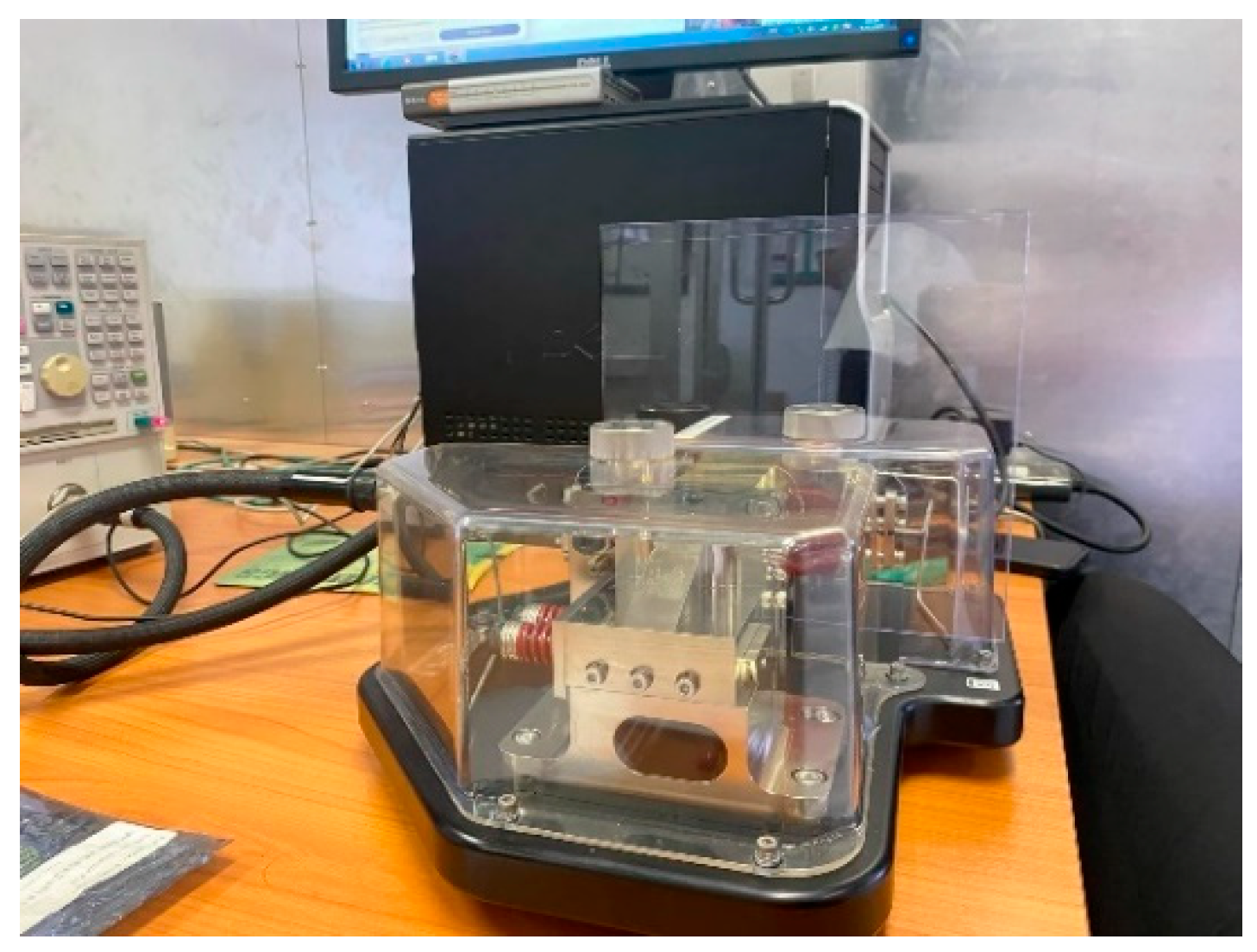
This section presents the iterative design evolution of the four-port wideband MIMO antenna for sub-6 GHz 5G applications. The antenna utilizes a polycarbonate substrate characterized by a dielectric constant εr = 2.8, loss tangent (tan δ) = 0.005448, and thickness (h) = 1 mm, as measured using an Agilent 85072A Split Cylinder Resonator (Keysight, Colorado Springs, CO, USA) before fabrication, as shown in Figure 1. Copper foil (thickness (t) = 0.017 mm, conductivity σ = 5.8 × 10⁷ S/m) serves as the conductive material.
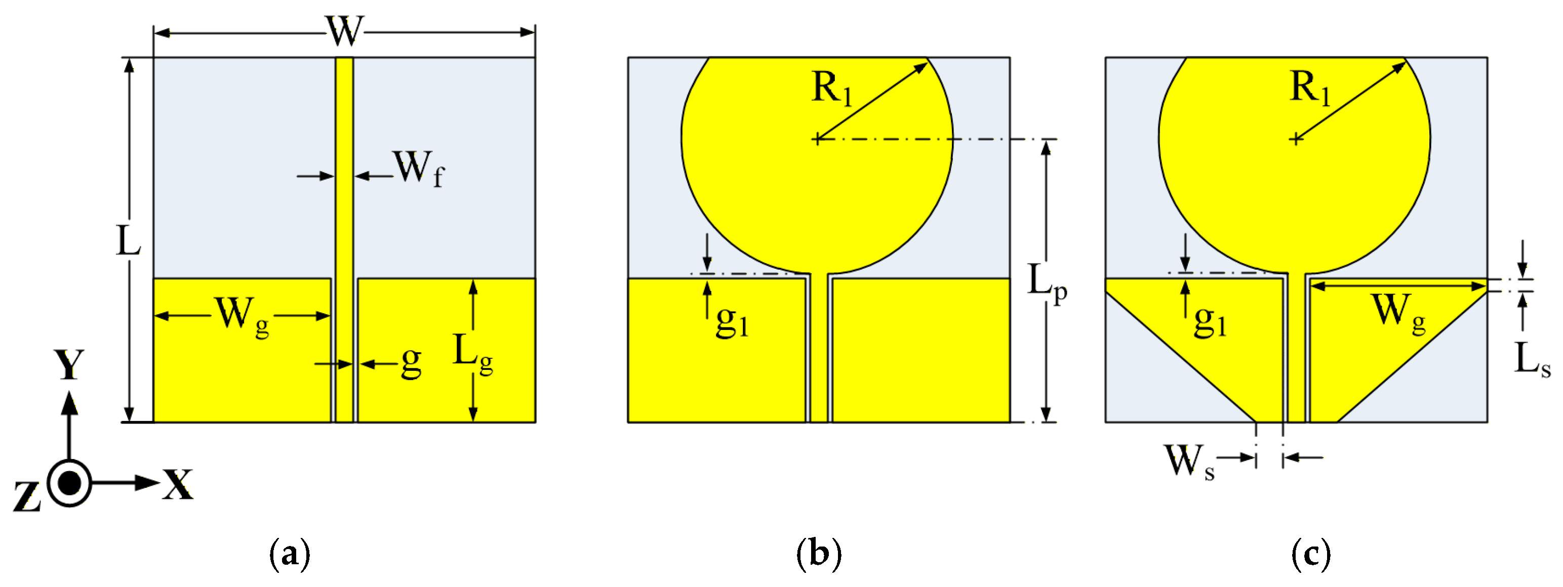
Figure 2 shows the evolution of the single-element wideband antenna design, comprising a conventional monopole antenna, a modified circular monopole antenna, and a modified circular monopole antenna combined with a triangular ground plane. The geometric parameters were optimized in CST Microwave Studio 2025 to reach |S11| < −10 dB over 0.7–7 GHz.
The fundamental equation for the design of a monopole antenna (Ant. I) is presented in Equation (1):
f r = c 4 L ε e f f ,
where c = 3 × 10⁸ m/s represents the speed of light in a vacuum, fr denotes the resonant frequency, and L signifies the monopole length. The initial dimensions of the modified circular patch radiator (Ant. II) were established utilizing the fundamental formulae for circular monopole antennas. The physical radius R1 was initially determined from the target resonant frequency fr, centered at 0.7 GHz, as delineated in Equations (2) and (3) [38]:
R 1 = F 1 + 2 h π ε r F ln π F 2 h + 1.7726 1 / 2 ,
where
F = 8.791 × 10 9 f r ε r .
Consequently, according to Equations (2) and (3), the radius of the circular monopole antenna was calculated as R1 = 74.4 mm. These equations served as the foundation before parametric optimization in CST Microwave Studio 2025, which involved the meticulous adjustment of parameters, including the patch radius R1, feed-ground gap g1, and ground width Wg to broaden the impedance bandwidth to 0.7–7 GHz.
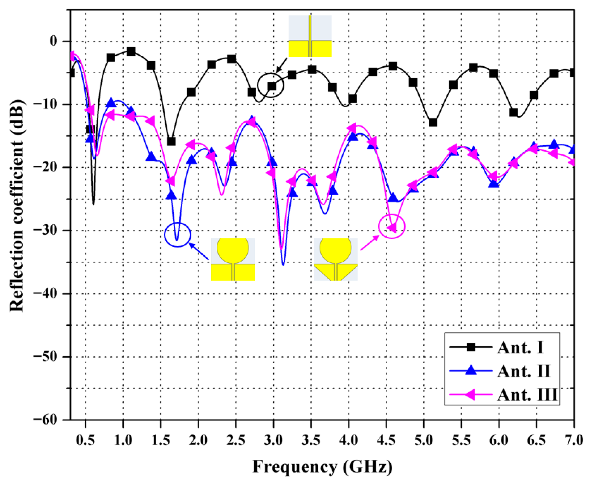
The design process began with a typical monopole antenna (Ant I), as shown in Figure 2a, which exhibited limited bandwidth (~0.6 GHz) with |S11| < −10 dB only at a single frequency point within the target 0.7–7 GHz band, as depicted in Figure 3. This bandwidth does not sufficiently cover the desired operating frequency range.
In contrast, the modified circular monopole antenna (Ant II) attained S11 values below −10 dB across almost the entire intended operating band. However, at the frequency of 0.8 GHz, the antenna still failed to fully cover the target operating range of 0.7 GHz to 7 GHz effectively, indicating that it is still insufficient to meet the desired frequency specifications.
Therefore, the modified circular monopole with triangular ground (Ant. III) is proposed, which can attain |S11| < −10 dB across the full target 0.7–7 GHz band. This performance improvement was achieved by adjusting several parameters, including the width (W) and length (L) of the substrate, the distance between the fed port and the circular patch center (Lp), the radius of the circular patch (R1), the ground plane width (Wg), and the gap between the ground and the patch (g1). The results are in good agreement with the expected performance of the antenna.
The structures of the four-port MIMO antennas were designed and simulated to determine the desired isolation performance, with a target isolation value of less than 15 dB. In particular, the simulation aimed to fulfill an isolation of >15 dB across the operating band to ensure that the antennas can effectively cover the required operating frequency bands.
The primary aim of the suggested MIMO antenna design is to assess essential characteristics, including the reflection coefficient (S11) and the transmission coefficient (S12) or isolation, which directly influence the efficacy of the MIMO system.
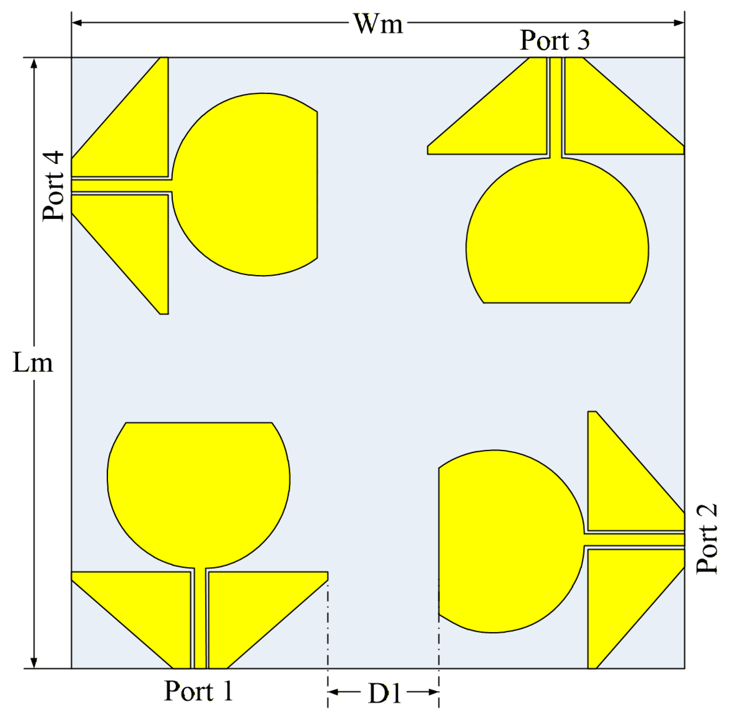
Figure 4 illustrates the configuration of the four-port MIMO antenna, which was constructed on a dielectric substrate of 500 × 500 mm2 polycarbonate. The structure was altered to achieve four-corner symmetry, with each port positioned perpendicularly to optimize polarization diversity, minimize the ECC, and facilitate 2 × 2 MIMO operations while preserving the D1 value between adjacent ports. The distance referred to as D1 is regulated to optimize signal separation, in accordance with the stipulated criteria (isolation of more than 15 dB). The configuration of each antenna comprises a modified circular patch and an inverted triangular ground plane. The dimensions of the dielectric plate are defined by the parameters W (width) and L (length), which directly influence the resonance frequency and bandwidth of the antenna.
The 500 × 500 mm2 aperture (1.17λ0 × 1.17λ0 at 0.7 GHz) is intentionally optimized for fixed infrastructure rather than handheld use. This large format enables D1 = 90 mm (0.21λ0 at 0.7 GHz) spacing for >15 dB isolation without metamaterials, high gain (10 dBi), and low-frequency extension to 0.7 GHz covering the n28 and n71 5G bands.
The substantial overall aperture of 500 × 500 mm2 was deliberately chosen to meet concurrent demands for bandwidth, isolation, and radiation objectives. The extensive physical aperture and an inter-element spacing of D1 = 90 mm allow the array to sustain a high realized gain (up to 10 dBi), facilitate near-omnidirectional coverage at lower frequencies, and maintain worst-case isolation > 15 dB, with >25 dB over a 63.5% bandwidth, while achieving ultra-low ECC and stable TARC and MEG performance. Decreasing the substrate dimensions or the element spacing would surely enhance mutual coupling and correlation, while diminishing the modified circular patch and triangle ground would jeopardize low-frequency extension to 0.7 GHz and decrease the achieved gain. Consequently, the suggested design is intentionally optimized as a large-format panel considered to be appropriate for infrastructure and testbed applications, rather than for very small handheld devices.
Although its size seems large compared to the compact designs (usually < 0.5λ0 × 0.5λ0 at the lowest frequency), this 1.17λ0 × 1.17λ0 aperture is justified by its intended use in 5G base station panels and radar systems. Its size allows for high gain (10 dBi), better isolation, and an expansive bandwidth, reaching up to 0.7 GHz.
The suggested four-port MIMO antenna is engineered to enhance communication in 5G networks, necessitating broad bandwidth and elevated isolation [39]. The initial design details for the presented antenna are listed in Table 1, which allow for the determination of changes in the features of the prototype MIMO antenna and support further analysis and improvement to reach optimal values for its real-world use.
F B W = f h i g h f l o w f c e n t e r × 100 f c e n t e r = f h i g h + f l o w 2 f c e n t e r = 7.0 + 0.7 2 = 3.85   GHz F B W = 7.0 0.7 3.85 × 100 % 163.63 %
According to Equation (4), the FBW value is roughly 163.63%, signifying an extensive bandwidth for the antenna. If the FBW exceeds 10%, it is classified as a wideband antenna; if the FBW surpasses 20%, it is categorized as a UWB antenna. The calculated antenna is therefore classified as a UWB antenna, which can support high-speed data transmission over a wide range of frequencies, including those used in 5G technology, the Internet of Things (IoT), MIMO systems, and radar detection.

3. Simulation Results

The proposed antenna was designed on a polycarbonate substrate with a dielectric constant of εr = 2.8, a thickness of h = 1 mm, and overall dimensions of 500 × 500 mm2. The antenna was simulated using the CST Microwave Studio software 2026. This section presents key simulated performance metrics—including S-parameters, the surface current distribution, TARC, MEG, ECC, and group delay—to validate the proposed antenna’s impedance matching, port isolation, diversity, and time-domain stability performance, which are essential for 2 × 2 MIMO operations with high spectral efficiency and low mutual coupling.

3.1. S-Parameters of the Simulation

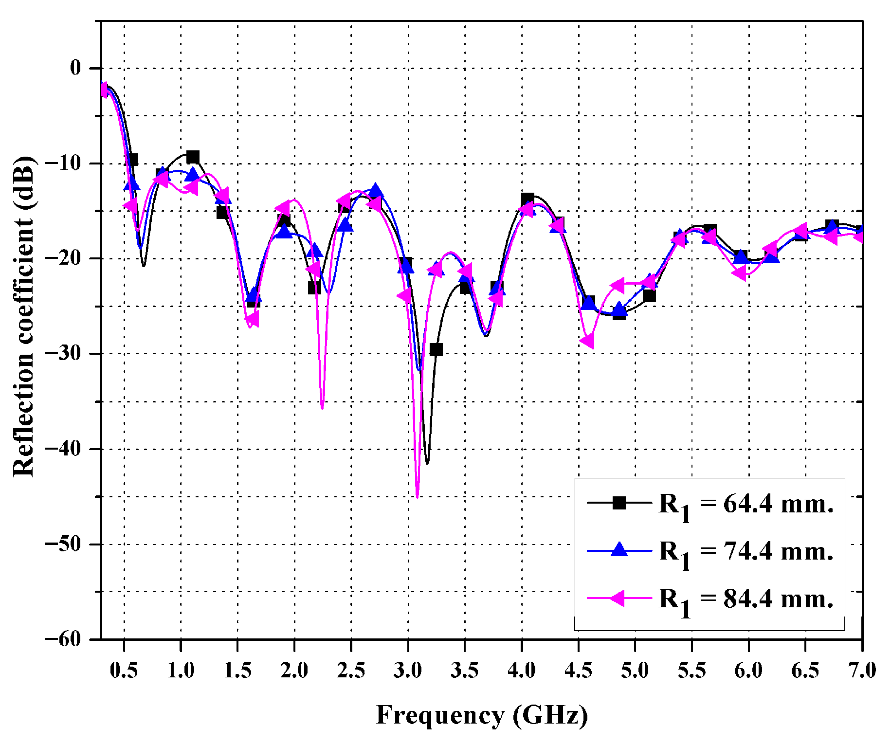
This section delineates the S-parameter simulation outcomes for the proposed antenna, validating its impedance bandwidth with ∣Sii∣ < −10 dB spanning the 0.7–7 GHz range (FBW ≈ 163.63%) and inter-port isolation with ∣Sij∣ < −25 dB (minimum ≈ −50 dB in certain intervals), as detailed in Table 2. These performance levels are essential for 2 × 2 MIMO operations in 5G sub-6 GHz networks, providing the required high spectral efficiency, minimal mutual coupling, and consistent matching throughout the operational band. Figure 5 shows the simulated reflection coefficient (S11) results after increasing the antenna radius (R1) to 64.4 mm, 74.4 mm, and 84.4 mm. The optimal radius was found to be R1 = 74.4 mm, and the portion of the circle exceeding the top edge of the substrate was trimmed to keep it within the substrate boundary. As a result, the impedance bandwidth reached 6.3 GHz, covering the frequency range from 0.7 GHz to 7 GHz.
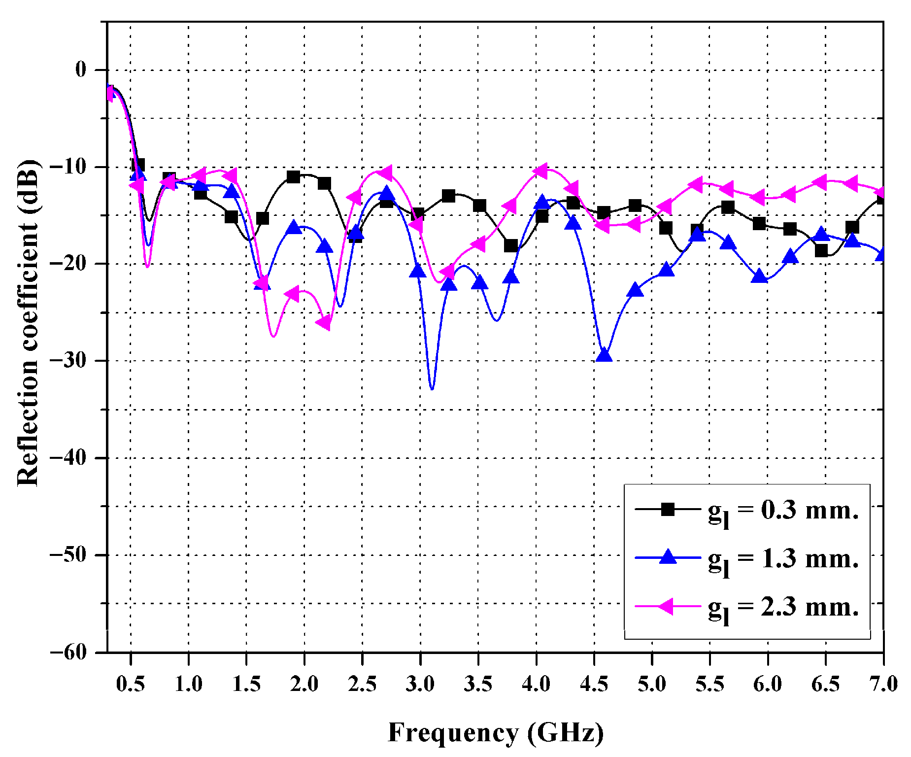
Figure 6 shows the simulated |S11| of the proposed antenna for three radiator–ground gaps (g1 = 0.3, 1.3, and 2.3 mm) across 0.3–7 GHz. Variation in g1 notably affects impedance matching, shifting resonant frequencies and altering the return-loss depth. The 1.3 mm gap yielded the deepest notches (below −10 dB) and the best overall matching, while smaller and larger gaps caused higher reflections and slightly detuned resonances. Therefore, a g1 value of 1.3 mm was chosen to achieve the best wideband performance.
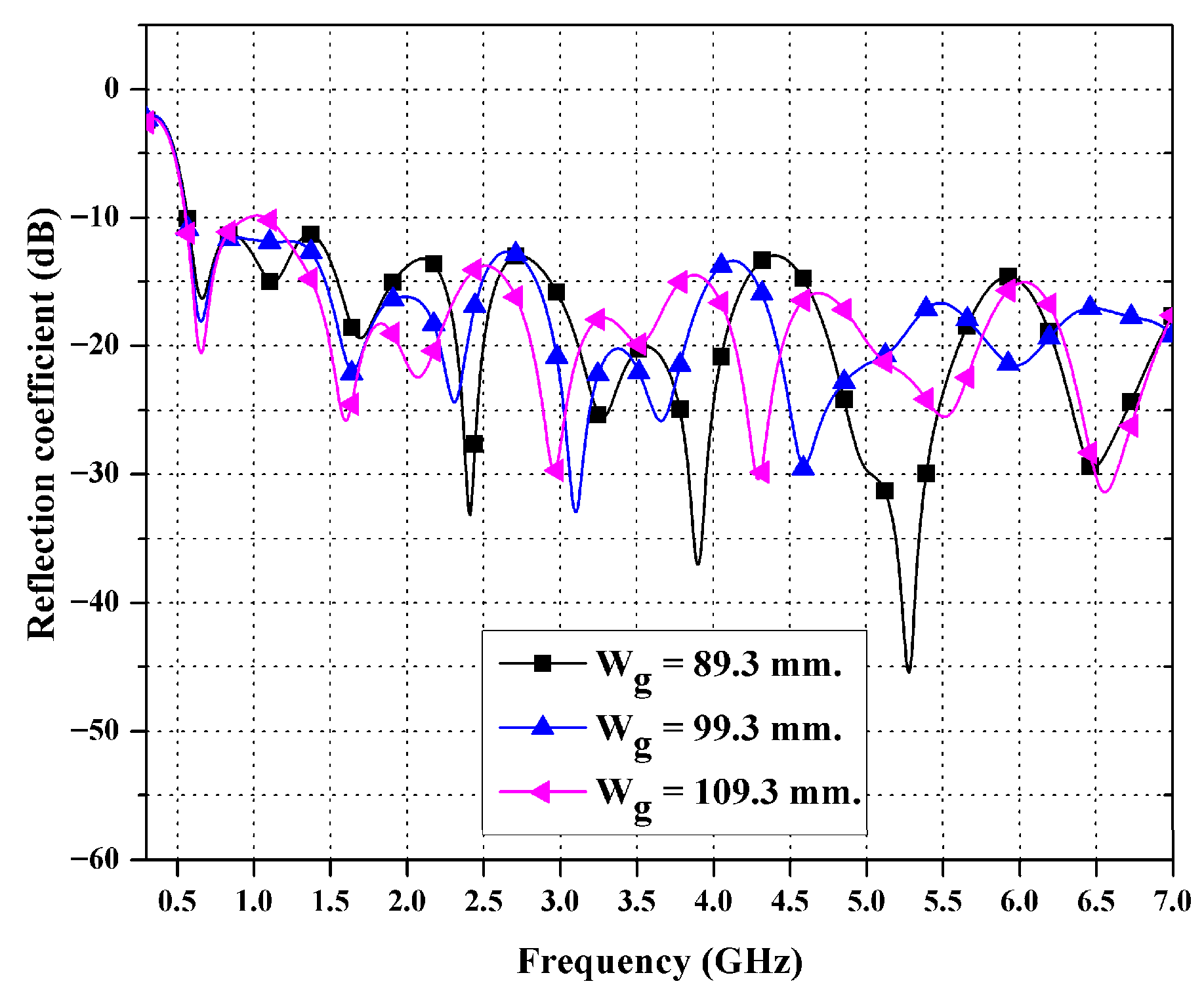
Figure 7 presents the simulated |S11| of the single-element antenna for ground widths of Wg = 89.3, 99.3, and 109.3 mm over 0.3–7 GHz. The Wg = 99.3 mm configuration achieved the lowest reflections (<−30 dB at several resonances) and optimal impedance matching across 0.7–7 GHz, whereas narrower and wider grounds showed higher |S11| and detuned resonances. Thus, Wg = 99.3 mm was identified as optimal, providing over 163% fractional bandwidth with |S11| < −10 dB, which is suitable for wideband 5G MIMO operations.
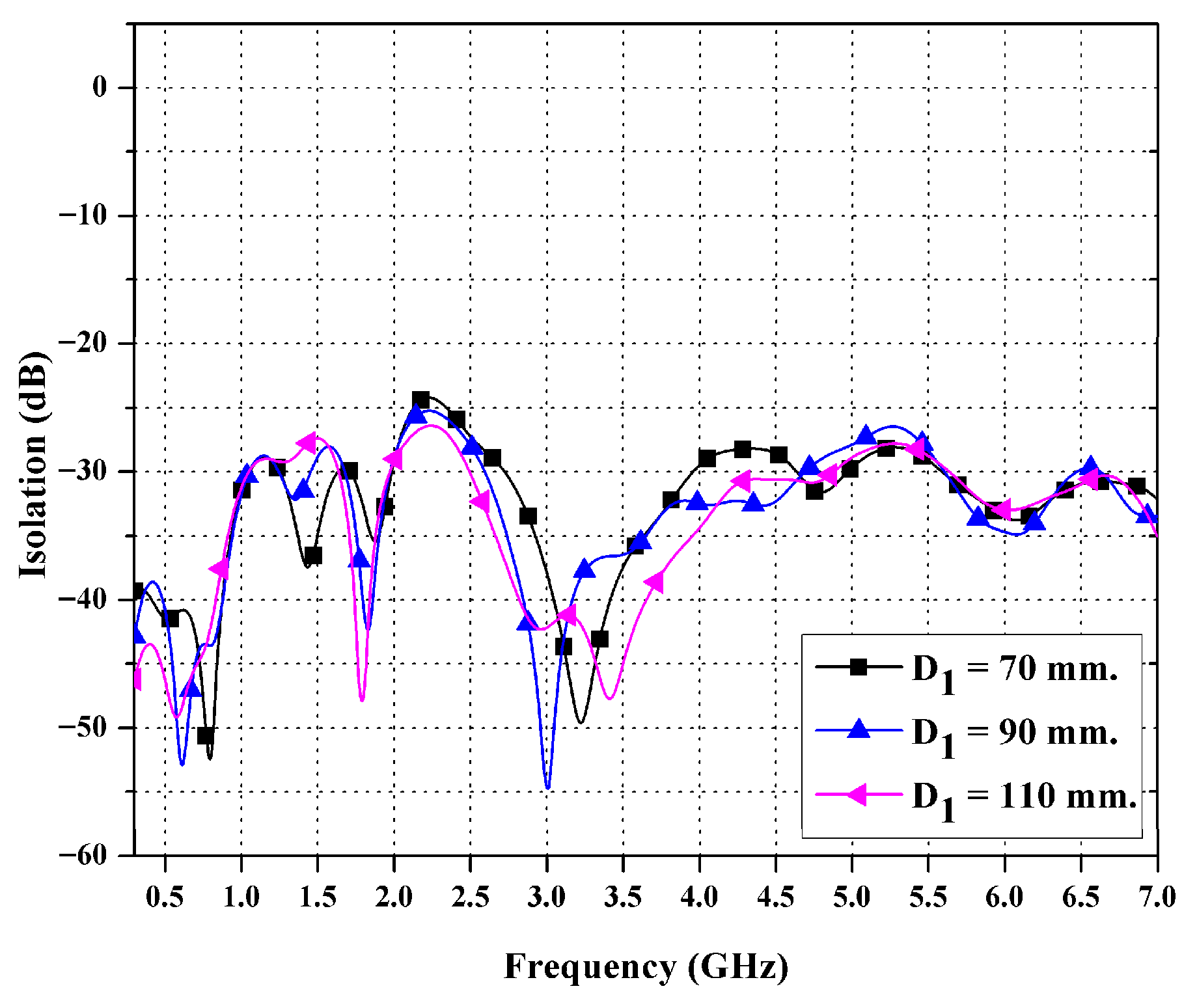
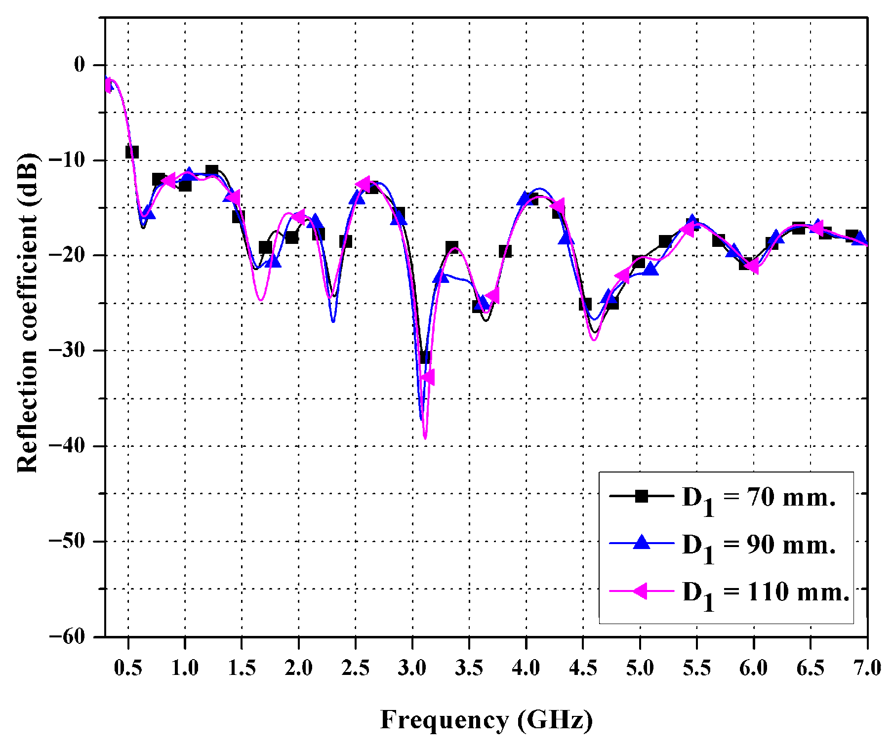
Figure 8 and Figure 9 show the simulated S-parameters of the proposed four-port MIMO antenna with different inter-element spacings (D1 = 70, 90, and 110 mm) across the 0.3–7 GHz frequency range. The transmission coefficient (S12), as shown in Figure 8, indicates that the configuration with D1 = 90 mm provides the best isolation, maintaining coupling levels below −50 dB between 0.7 and 1.8 GHz. The observed improvement is mainly due to the effective reduction in near-field mutual currents between the radiating elements that are close to each other. In comparison, shorter or longer spacings cause increased field interactions or detuned current paths, thus elevating the coupling level. Consequently, it can be inferred that augmenting the gap D1 markedly diminishes coupling between the ports and enhances isolation [40,41].
Figure 9 shows the |S11|, where all designs can be seen to exhibit satisfactory impedance matching (<−10 dB) over the 0.7–7 GHz band. The D1 = 90 mm configuration showed the most consistent impedance across a wide range of frequencies, suggesting optimal electromagnetic coupling within the array. These findings corroborate the significance of suitable inter-element separation in achieving both robust isolation and wideband matching. Thus, the spacing D1 = 90 mm optimizes MIMO performance.
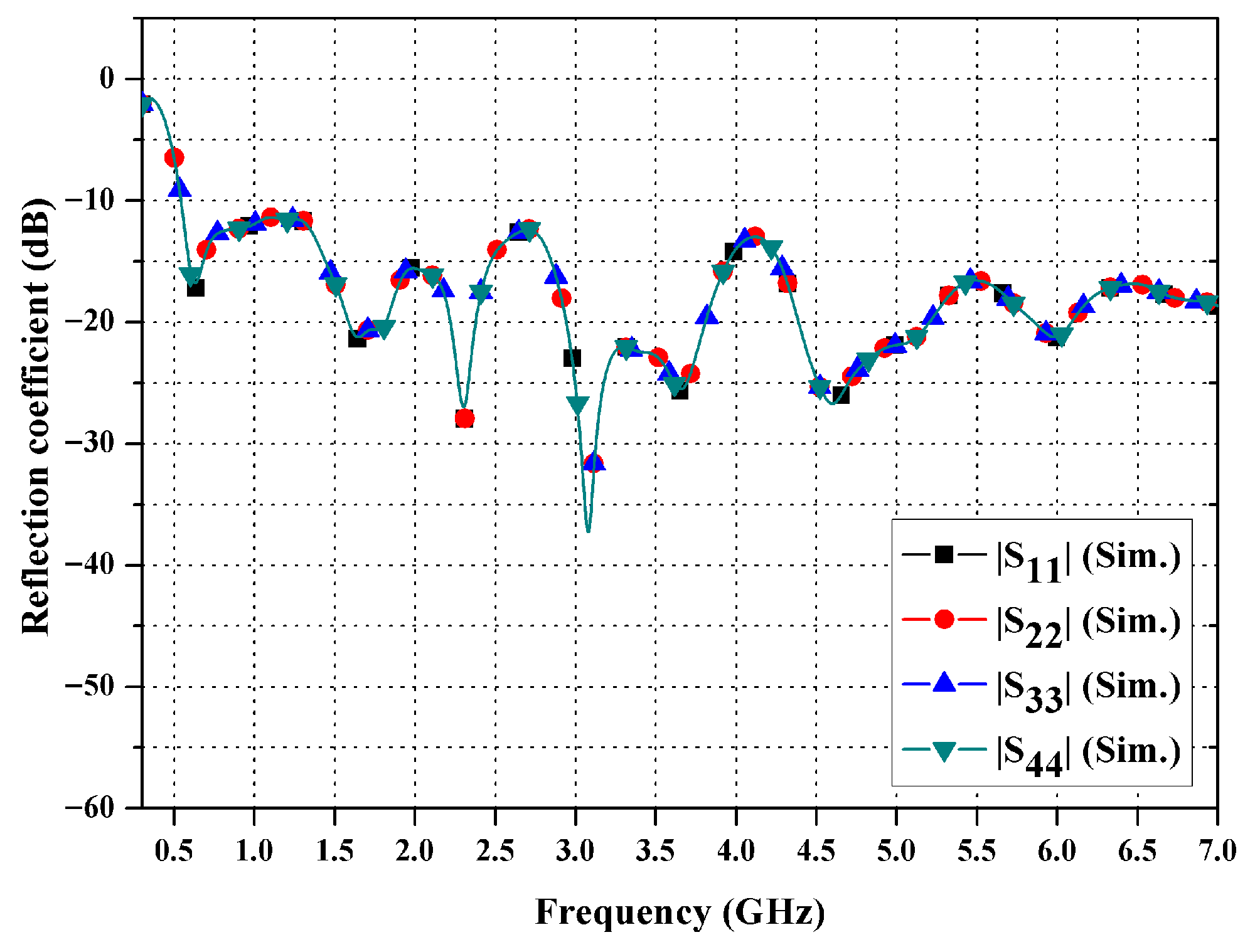
The proposed antenna is constructed on a square dielectric substrate and features four identical modified circular radiating elements, which are symmetrically placed at the corners. This compact structure achieves polarization and spatial diversity, and the reflection coefficient results shown in Figure 10 indicate that all ports (S11, S22, S33, S44) exhibit values below −10 dB across the wide operating frequency band of 0.7–7 GHz, which covers the sub-6 GHz spectrum for 5G communication networks. The antenna elements exhibit low coupling and excellent impedance matching, which further confirms their suitability for use in modern MIMO wireless systems.
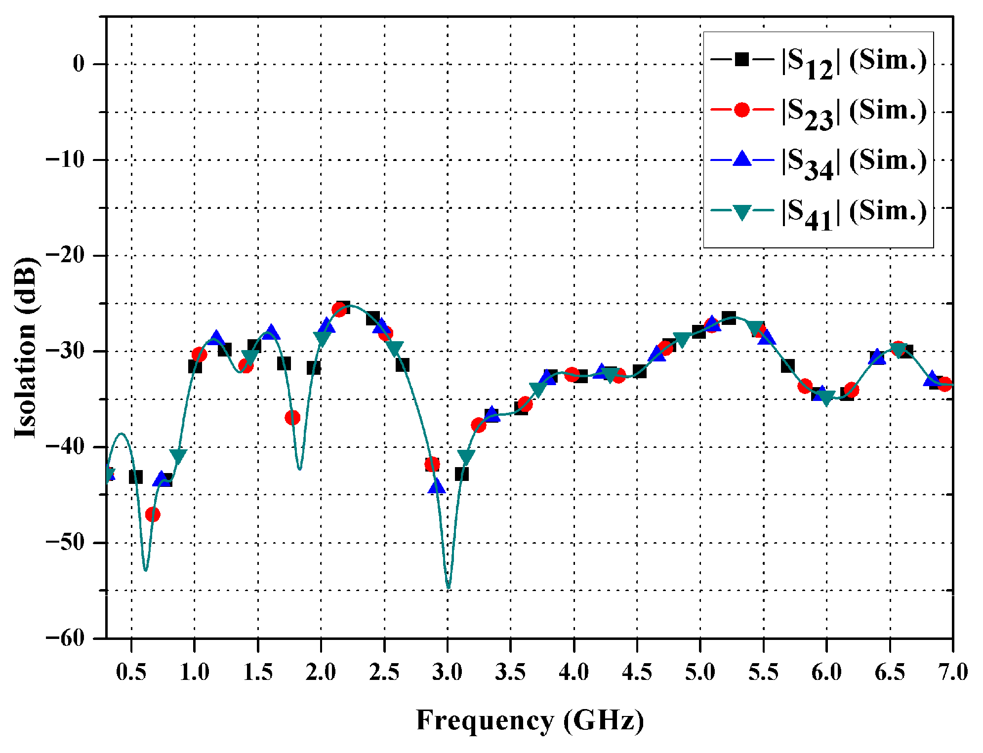
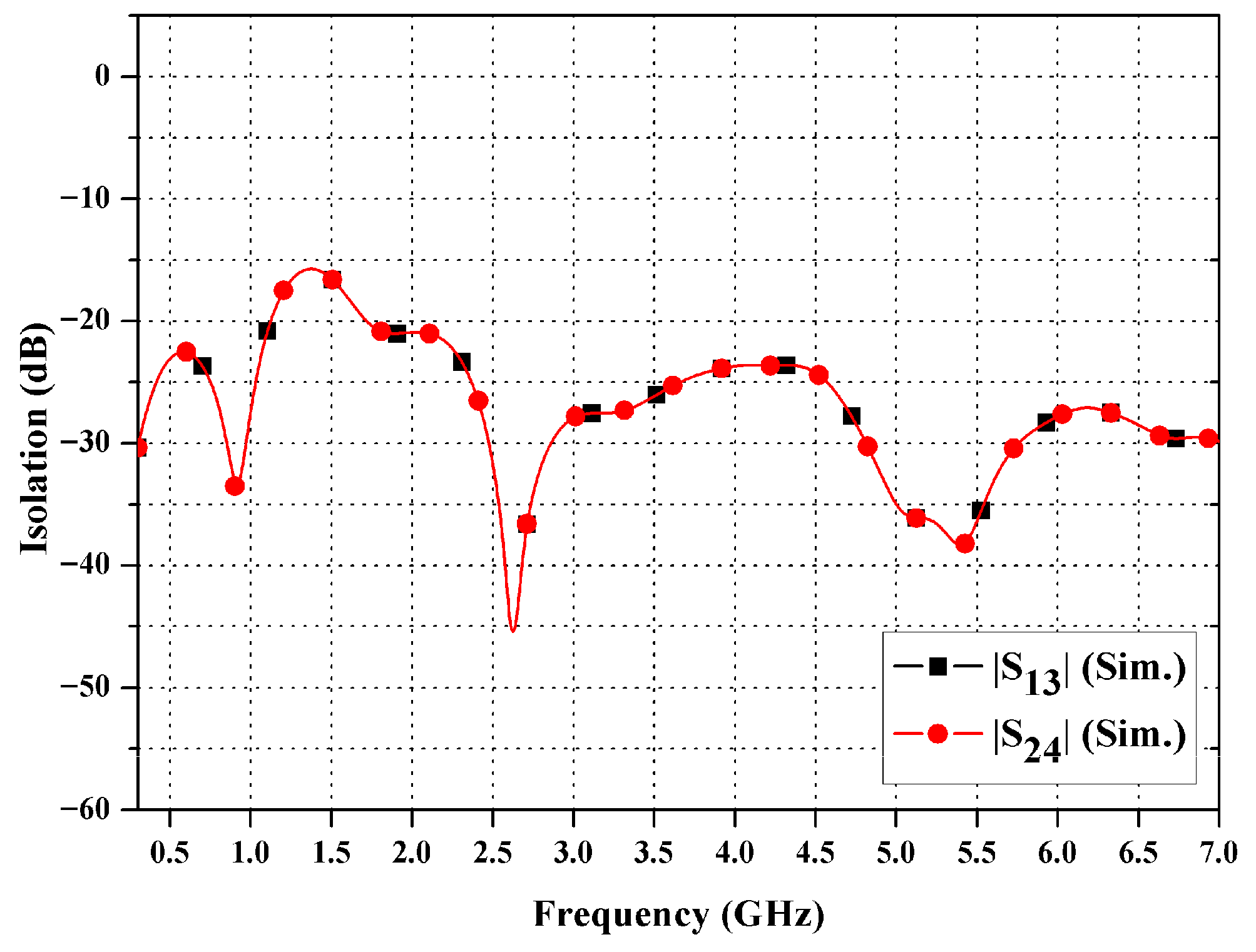
Figure 11 and Figure 12 depict the isolation values (S12, S23, S34, S41, S13, S24) of the ports of the MIMO antenna configured at 90° and 180°, respectively. In the 0.7–7 GHz spectrum, all coupling levels remained below −15 dB (worst-case), as quantified in Table 2 (with peak value at 55 dB). The superior isolation (>25 dB/63.5% BW) stems from current confinement, yielding reduced ECC and efficient support for sub-6 GHz 5G applications [42]. The antenna exhibits consistent performance and robust isolation over the full spectrum.
The significant isolation seen across the entire operational range suggests that the proposed array benefits from both the optimized spacing between elements (D1 = 90 mm) and built-in methods for reducing coupling. The orthogonal arrangement of radiating elements combined with inverted triangular ground planes disrupts primary electric/magnetic coupling pathways along the substrate, resulting in reduced mutual admittances across ports. As elaborated in Section 3.4, the resultant current distribution around excited elements and restricted induced currents on non-excited ports directly enable the recorded isolation (i.e., >25 dB) and exceptionally low ECC across 0.7–7 GHz.
The >25 dB isolation across 63.5% of the bandwidth significantly exceeds typical smartphone MIMO requirements (15–20 dB), achieved through passive orthogonal geometry without the need for metamaterials or DGSs.

3.2. TARC and MEG

The TARC [43] serves as a complete statistic for assessing the active reflection characteristics of MIMO antennas when several ports are simultaneously excited, incorporating both self-reflection and mutual coupling effects via phase fluctuations of input signals. It is defined as shown in Equation (5):
T A R C = i = 1 N b i 2 i = 1 N a i 2 ,
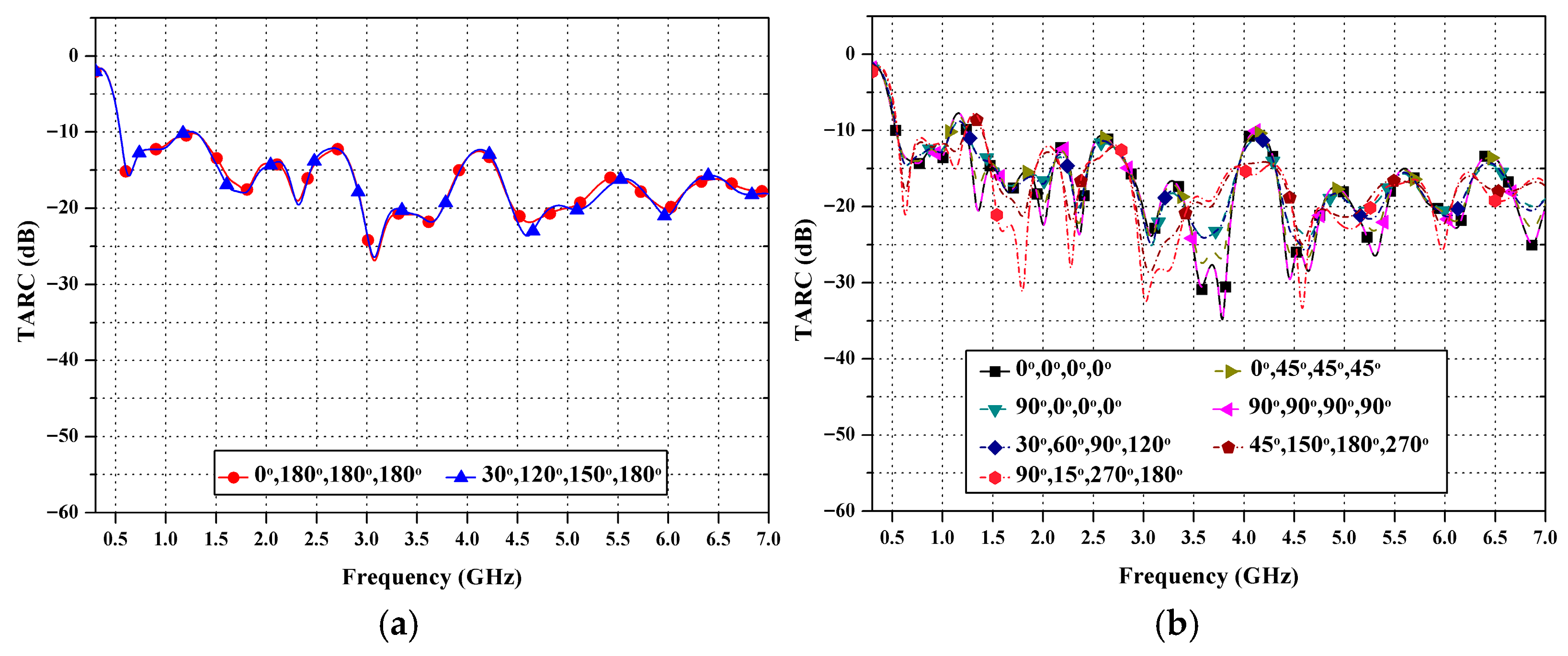
where N specifies the number of ports, and ai and bi denote the incident and reflected signals at each port, respectively. Figure 13a,b depict the simulated TARC results for various phase configurations. The proposed antenna achieves TARC < −10 dB across 0.7–7 GHz for primary phase configurations, as shown in Figure 13a. While some extreme cases in Figure 13b show minor exceedances due to destructive phase alignment, the overall diversity gain and low ECC confirm its excellent suitability for MIMO applications.
To assess the most unfavorable conditions, the extreme phase configurations depicted in Figure 13b were examined. This analysis revealed that the highest observed TARC exceedances were confined to −6 dB, occurring at particular destructive alignments within a bandwidth of less than 1%. These results are still deemed acceptable for practical four-port MIMO applications, in accordance with IEEE Std 149-2021 [44]. This assertion is further substantiated by the ultra-low ECC and isolation performance, as detailed in Table 2.
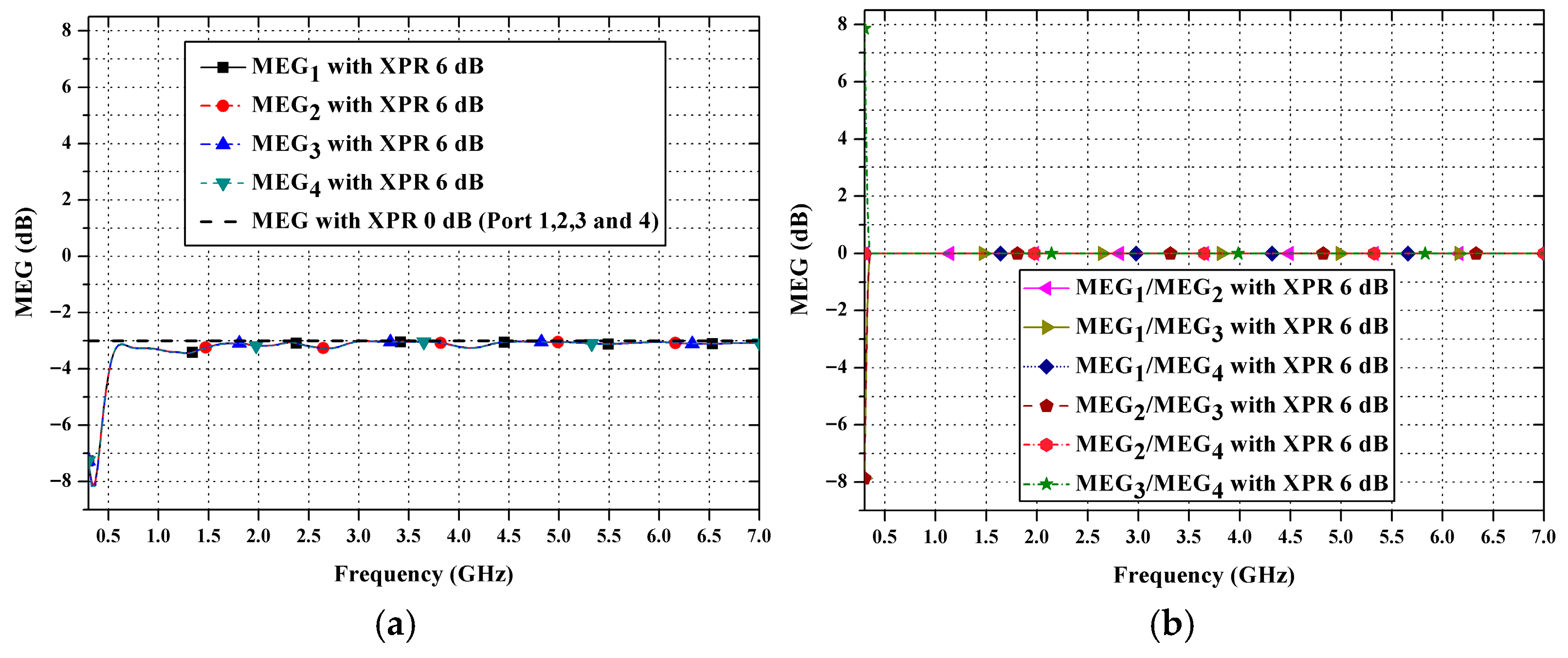
The MEG analysis assumes a uniform angular power distribution over the full sphere (computed via 3D far-field integration with Δθ = 2°, Δφ = 2°) and standard polarization models with Cross-Polarization Ratio (XPR) values of 0 dB (isotropic) and 6 dB (realistic urban microcell, per 3GPP TR 38.901 [45]). A similar performance in terms of MEG (in this study, about −3 dB across all ports) confirms suitable diversity for environments with multiple paths, thus enhancing the performance of multiple-input multiple-output (MIMO) systems used in 5G base stations that operate below 6 GHz.
Figure 14a,b depict the MEG outcomes of the four-port MIMO antenna [46] assessed at XPR = 0 dB and 6 dB across ports 1–4. The MEG was approximately −3 dB across the frequency range 0.7–7 GHz, indicating balanced signal reception at each port and demonstrating the MIMO system’s efficacy in multipolarized propagation environments. The computation of MEG adheres to Equations (6) and (7), expressed as
M E G i = P r e c P i n c = X P R G θ i P θ Ω + G ϕ i Ω P ϕ Ω 1 + X P R   d Ω
or
M E G i = 0 2 π 0 π X P R 1 + X P R G θ θ , ϕ P θ θ , ϕ + 1 1 + X P R G ϕ θ , ϕ P ϕ θ , ϕ sin θ d θ d ϕ ,
where Prec denotes the received power; Pinc signifies the incident power; Gθ and Gϕ represent the antenna gains for θ- and φ-polarizations, respectively; Pθ and Pϕ are the power density components in each polarization; and XPR indicates the ratio between co-polarized and cross-polarized components. XPR values of 0 dB and 6 dB indicate distinct polarization circumstances, whereas MEG values approaching −3 dB validate the balanced and efficient signal-receiving capacity of the proposed wideband MIMO antenna [47].

3.3. ECC and Group Delays

This section examines the ECC [47] and group delay of the presented antenna. These are critical metrics for assessing its performance with various signal types and its temporal stability for sub-6 GHz 5G applications.
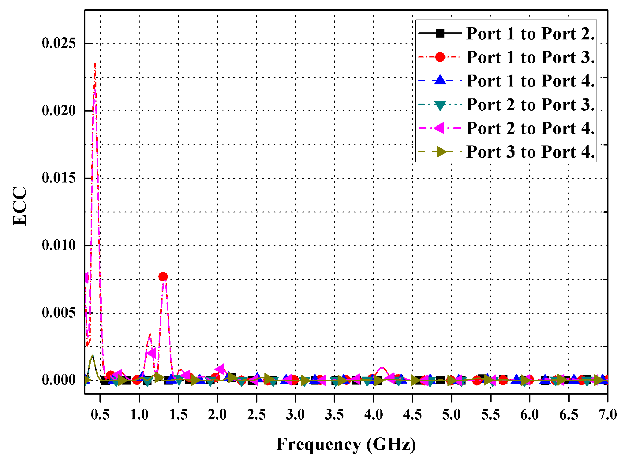
The ECC of the suggested antenna is depicted in Figure 15. These values were determined using complete 3D far-field radiation patterns generated using CST Microwave Studio with an angular sampling resolution of Δθ = 2° and Δφ = 2° across the entire sphere (0° ≤ θ ≤ 180°, 0° ≤ φ ≤ 360°). The ECC values between antenna pairs (1–2), (1–3), (1–4), (2–3), (2–4), and (3–4) were calculated via numerical double integration of Equations (8)–(13) with sinθ weighting. For validation, S-parameter-based ECC computation under a uniform multipath assumption produced comparable trends. The simulation results reveal ECC values consistently below 0.008 throughout the 0.7–7 GHz band (well under the 0.5 limit), confirming high diversity performance, low mutual coupling, and independent operation of antenna elements and, thus, demonstrating reliable wideband MIMO capacity.
E C C 12 = 4 π E 1 θ , ϕ × E 2 θ , ϕ d Ω 2 4 π E 1 θ , ϕ 2 d Ω 4 π E 2 θ , ϕ 2 d Ω ,
E C C 13 = 4 π E 1 θ , ϕ × E 3 θ , ϕ d Ω 2 4 π E 1 θ , ϕ 2 d Ω 4 π E 3 θ , ϕ 2 d Ω ,
E C C 14 = 4 π E 1 θ , ϕ × E 4 θ , ϕ d Ω 2 4 π E 1 θ , ϕ 2 d Ω 4 π E 4 θ , ϕ 2 d Ω ,
E C C 23 = 4 π E 2 θ , ϕ × E 3 θ , ϕ d Ω 2 4 π E 2 θ , ϕ 2 d Ω 4 π E 3 θ , ϕ 2 d Ω ,
E C C 24 = 4 π E 2 θ , ϕ × E 4 θ , ϕ d Ω 2 4 π E 2 θ , ϕ 2 d Ω 4 π E 4 θ , ϕ 2 d Ω ,
E C C 34 = 4 π E 3 θ , ϕ × E 4 θ , ϕ d Ω 2 4 π E 3 θ , ϕ 2 d Ω 4 π E 4 θ , ϕ 2 d Ω ,
where Ei (θ,ϕ) represents the electric field radiated from the antenna element at port i.
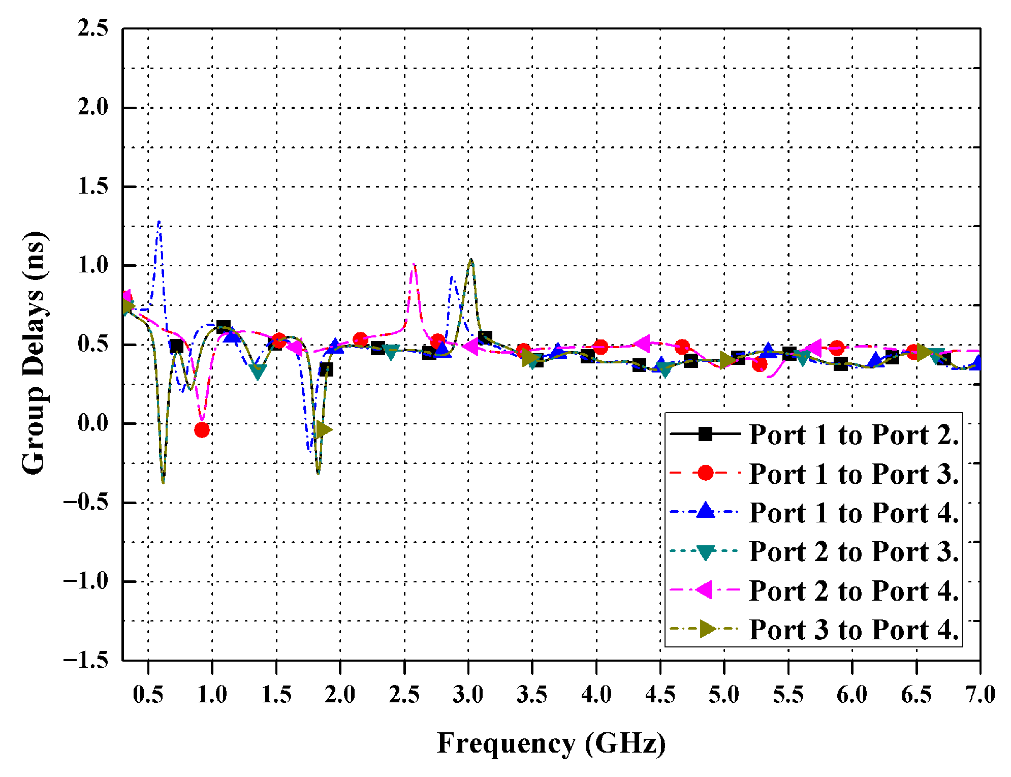
Figure 16 illustrates the Group Delay (GD) characteristics for all port pairings of the four-port MIMO antenna (1→2, 1→3, 1→4, 2→3, 2→4, and 3→4). In the primary operating band of 0.7–7 GHz, the GD values remain at approximately 0.5 ns with slight fluctuations (±0.75 ns), signifying excellent phase linearity and no signal distortion. Minor peaks at 0.6, 0.9, 1.75, 2.5, and 3 GHz indicate narrowband resonances that do not substantially impact performance. The consistent GD response throughout the band indicates homogeneous phase propagation and minimal temporal dispersion among the antenna elements, demonstrating that the transmitted signals preserve waveform integrity and guarantee minimal pulse distortion and stable synchronization within the MIMO system. Thus, the suggested antenna design delivers exceptional wideband time-domain performance, making it ideal for high-speed and dependable wireless communication applications, including sub-6 GHz 5G MIMO systems.

3.4. Surface Current Distribution

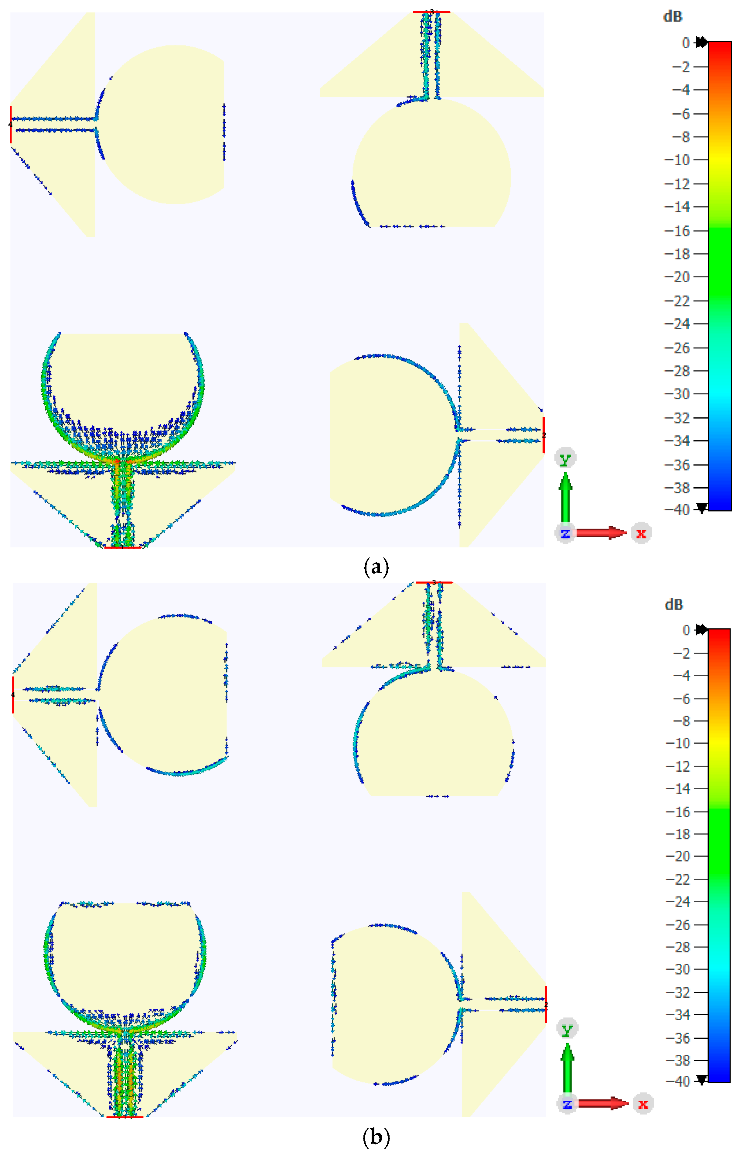
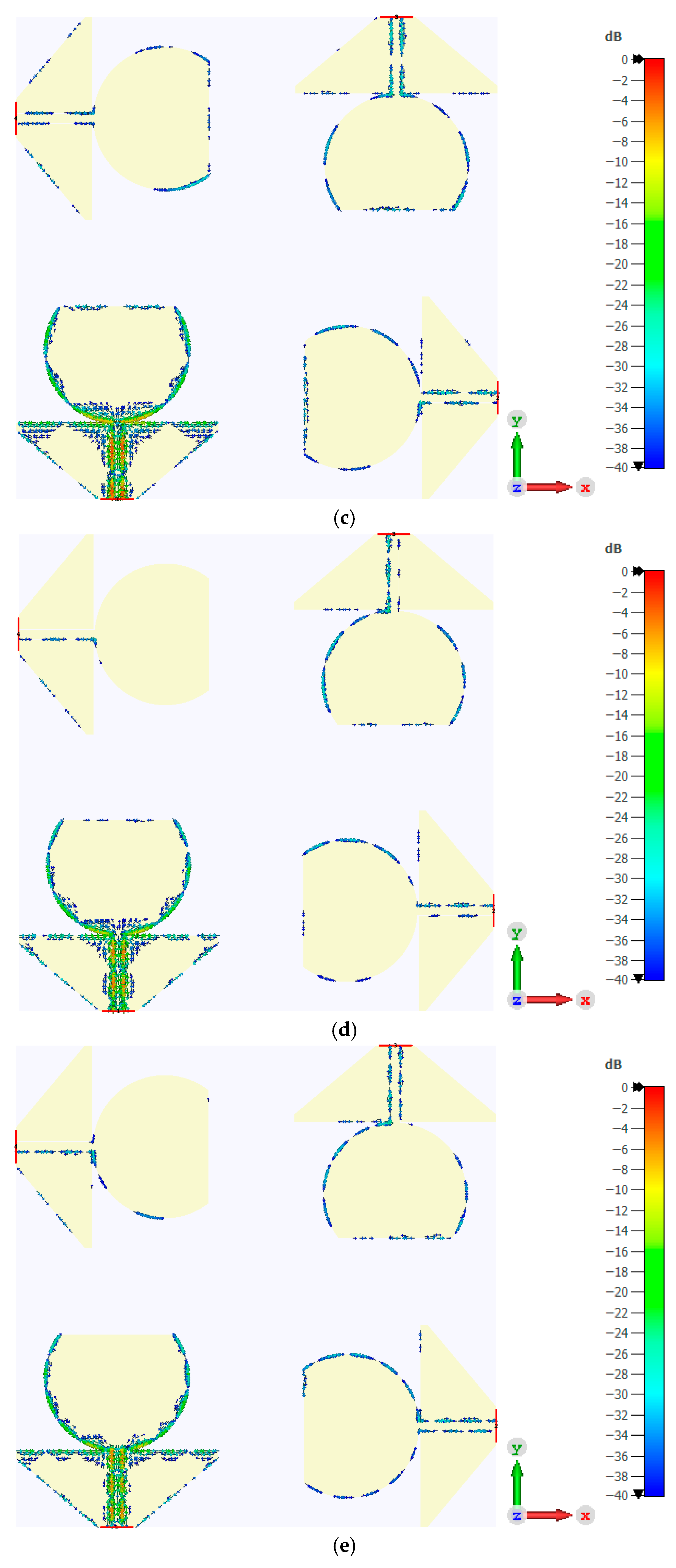
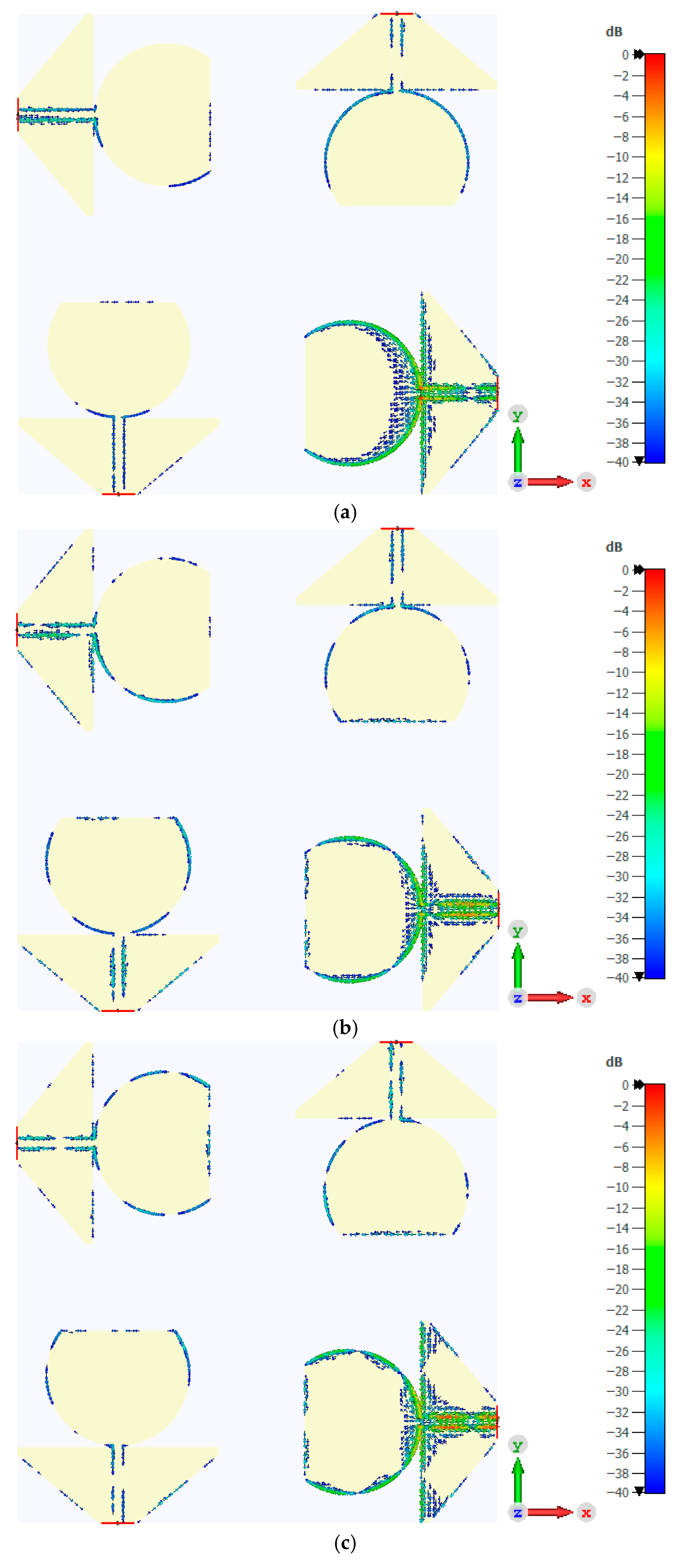
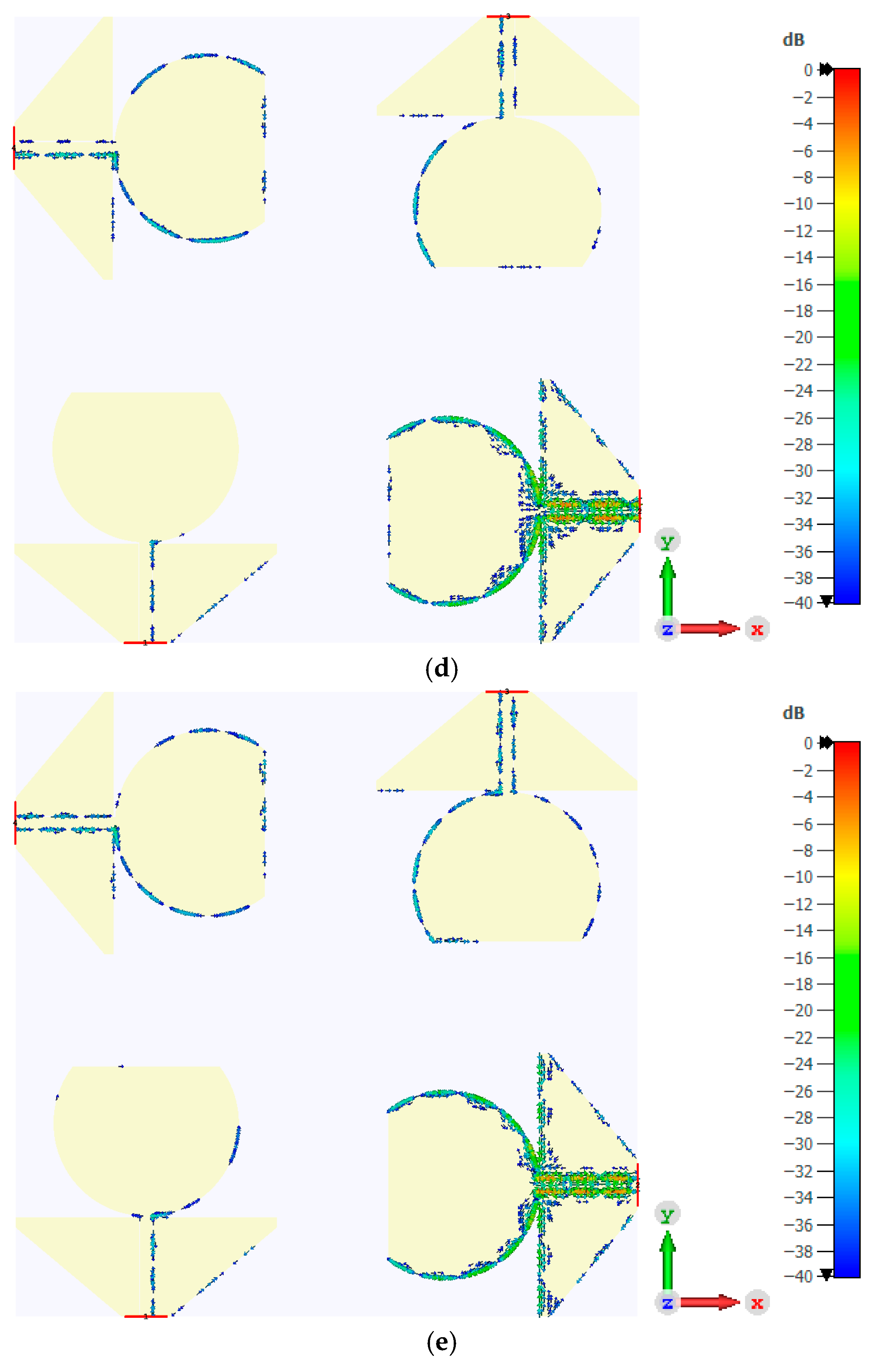
This section examines the surface current distribution on the proposed antenna, in order to clarify the physical principles responsible for its low mutual coupling and enhanced port decoupling over the 0.7–7 GHz operating range. Simulated outcomes at typical frequencies (0.7 GHz, 1.8 GHz, 2.6 GHz, 3.6 GHz, and 4.6 GHz) with single-port stimulation demonstrate current confinement to the patch and feed-ground junction of the excited element, whereas non-excited ports exhibit minimal activity. The orthogonal symmetry and triangular ground configuration effectively inhibit cross-port current propagation, confirming the antenna’s diversity performance for sub-6 GHz 5G MIMO systems.
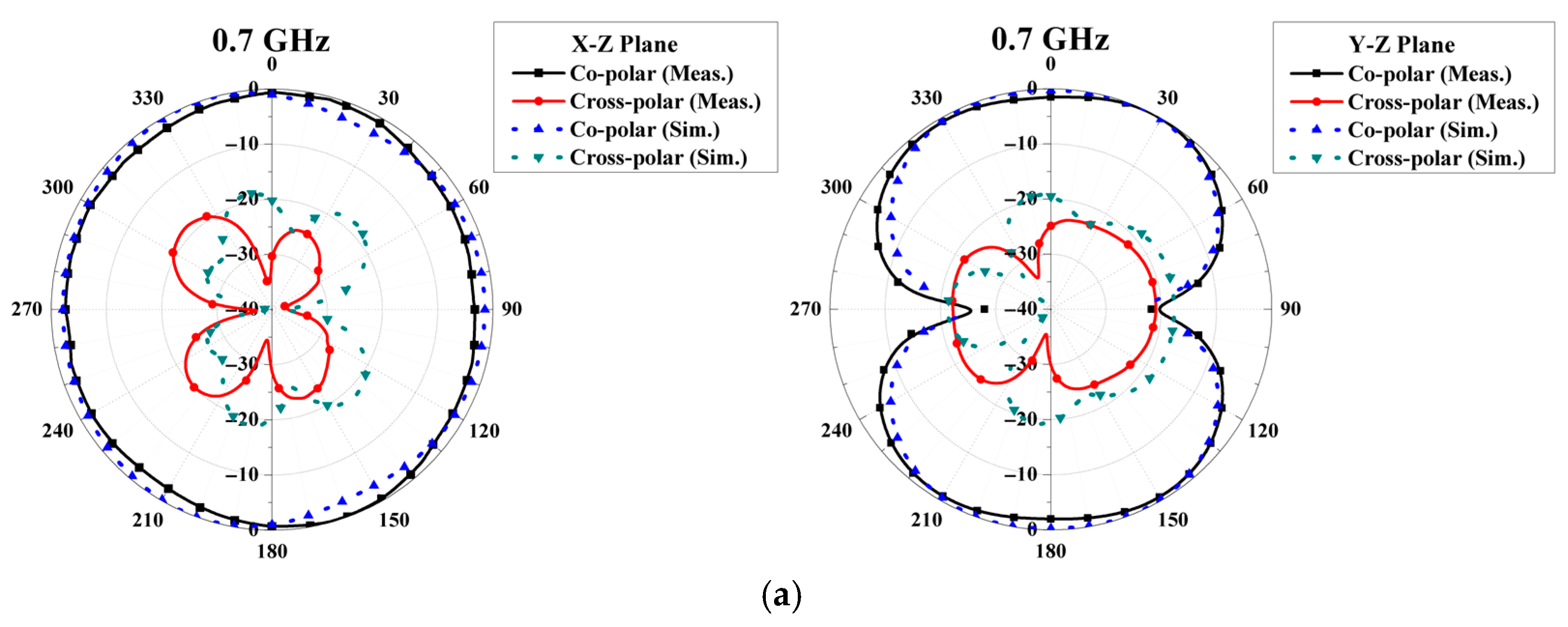
Figure 17 and Figure 18 illustrate the surface current distribution of the four-port MIMO antenna operating over the frequency range of 0.7–7 GHz, with measurements made at 0.7, 1.8, 2.6, 3.6, and 4.6 GHz, which are typical frequencies in 4G and 5G communication systems. The activation of ports 1 and 2 (shown in Figure 17 and Figure 18, respectively) creates higher current levels (represented by brighter colors, as detailed on the right), mainly around the radiating patch and the areas near the feeders of the excitation ports. The remaining three parts exhibit minimal currents (predominantly in blue), signifying minimal coupling (i.e., high isolation). The excited flow patterns of each element are independent of each other due to the orthogonal configuration of the elements, guaranteeing that the radiation direction of each port is mostly independent. When the power is switched between ports, the current changes in response but stays focused around the excitation elements, thereby affirming the structure’s ability to inhibit current propagation across the elements and enhance isolation and TARC control of the four-port MIMO system across the entire operational frequency range.
From an electromagnetic perspective, these current distributions elucidate the physical processes underlying the lowering of strong coupling. At lower frequencies (0.7–1.8 GHz), the extensive polycarbonate substrate can facilitate surface-wave and quasi-TEM coupling among elements; however, the inverted triangular grounds establish localized return paths that disrupt these surface currents, hindering their coherent flow toward adjacent ports, as shown in Figure 17a,b. At elevated frequencies (3.6–4.6 GHz), as depicted in Figure 17c–e, where the inter-element spacing D1 nears one wavelength, the orthogonal alignment of the modified circular patches diminishes co-polarized field overlap. At the same time, the triangular grounds disrupt the magnetic flux connecting adjacent feeds, consequently attenuating both capacitive and inductive coupling pathways. From an equivalent circuit perspective, each element functions as a multi-resonant RLC radiator, specifically in the TM01, TM11, and TM21 modes. These modes show minimal coupling to nearby elements, which is due to the small remaining mutual impedances. This behavior directly explains the observed isolation levels (ranging from 25 to 50 dB), the exceptionally low ECC (less than 0.008), and the consistent TARC performance across the 0.7–7 GHz frequency band. This current confinement mechanism, combined with multi-mode diversity, enables the unprecedented FBW = 163.63% with compact radiator R1 = 74.4 mm, distinguishing the design from conventional UWB MIMO antennas requiring complex decoupling structures.

4. Measurement Results

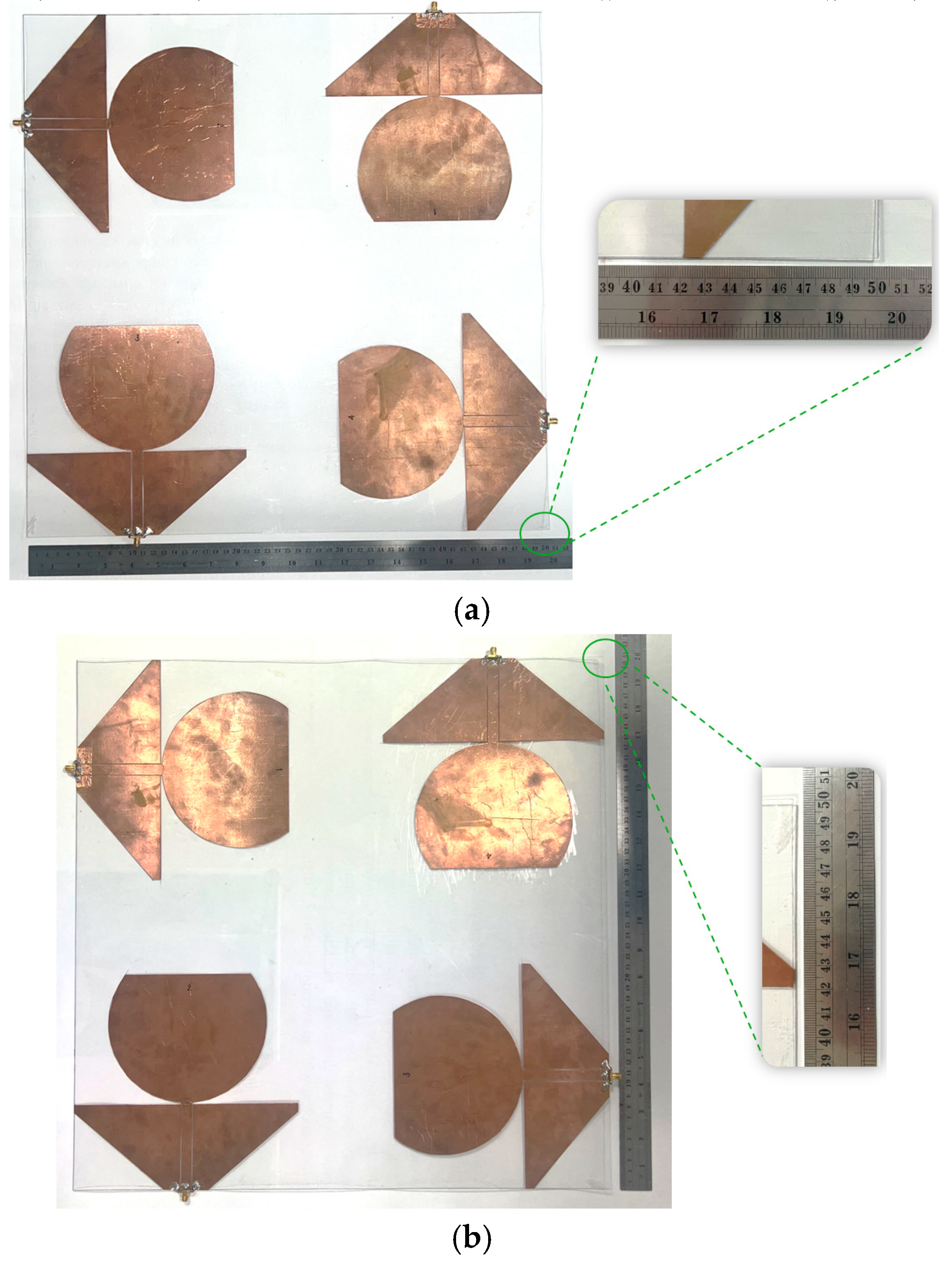
A wideband MIMO antenna was subsequently developed, as shown in Figure 19, in order to assess the antenna’s performance and, thus, its suitability for practical wideband MIMO applications. The assessment encompassed evaluating all pertinent parameters, including impedance matching to confirm appropriate input adaptation, radiation patterns to examine directional characteristics and field distribution, and gain to measure signal strength across the antenna’s operational frequency range in MIMO operations.

4.1. S-Parameters

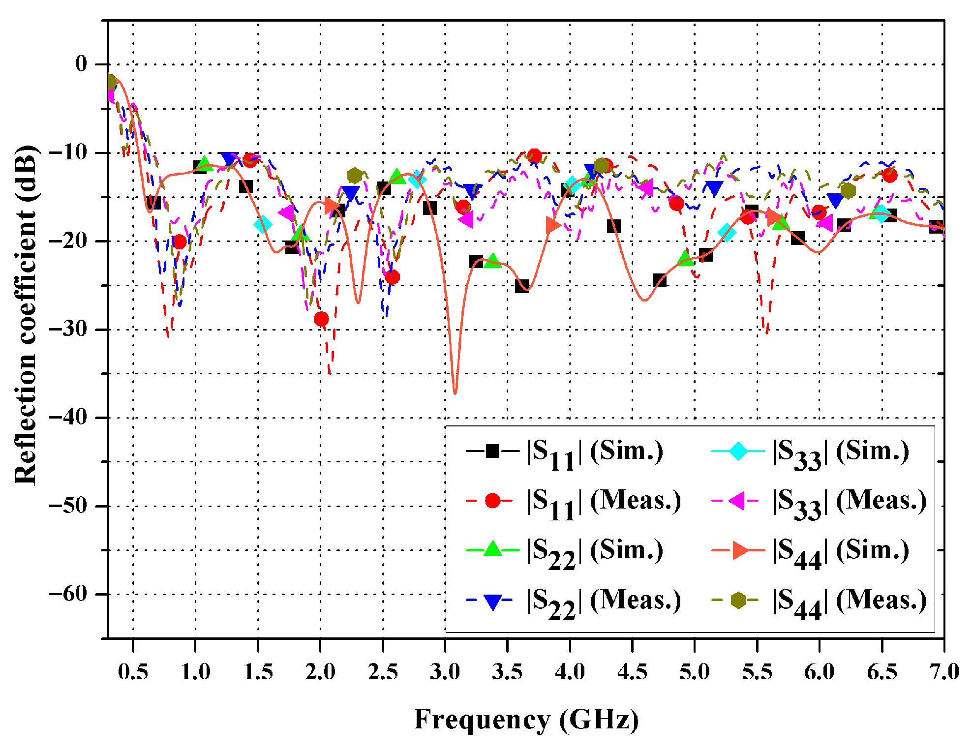
Figure 20 shows the measured and simulated reflection coefficients (∣S11∣, ∣S22∣, ∣S33∣, and ∣S44∣) for the four-port MIMO antenna, covering the 0.3–7 GHz range. All ports show ∣Sii∣ values below −10 dB across several bands, which supports sub-6 GHz standards. Ports 1 and 2 have deeper minima (less than −25 dB) at their main resonances; while ports 3 and 4 have similar matching characteristics, they present slight frequency shifts and less pronounced minima. The close match between the simulation and measurement results confirms the effectiveness of the decoupling structures in maintaining broad impedance matching. Minor differences are attributed to fabrication tolerances, material losses, and the effects of the SMA connectors.
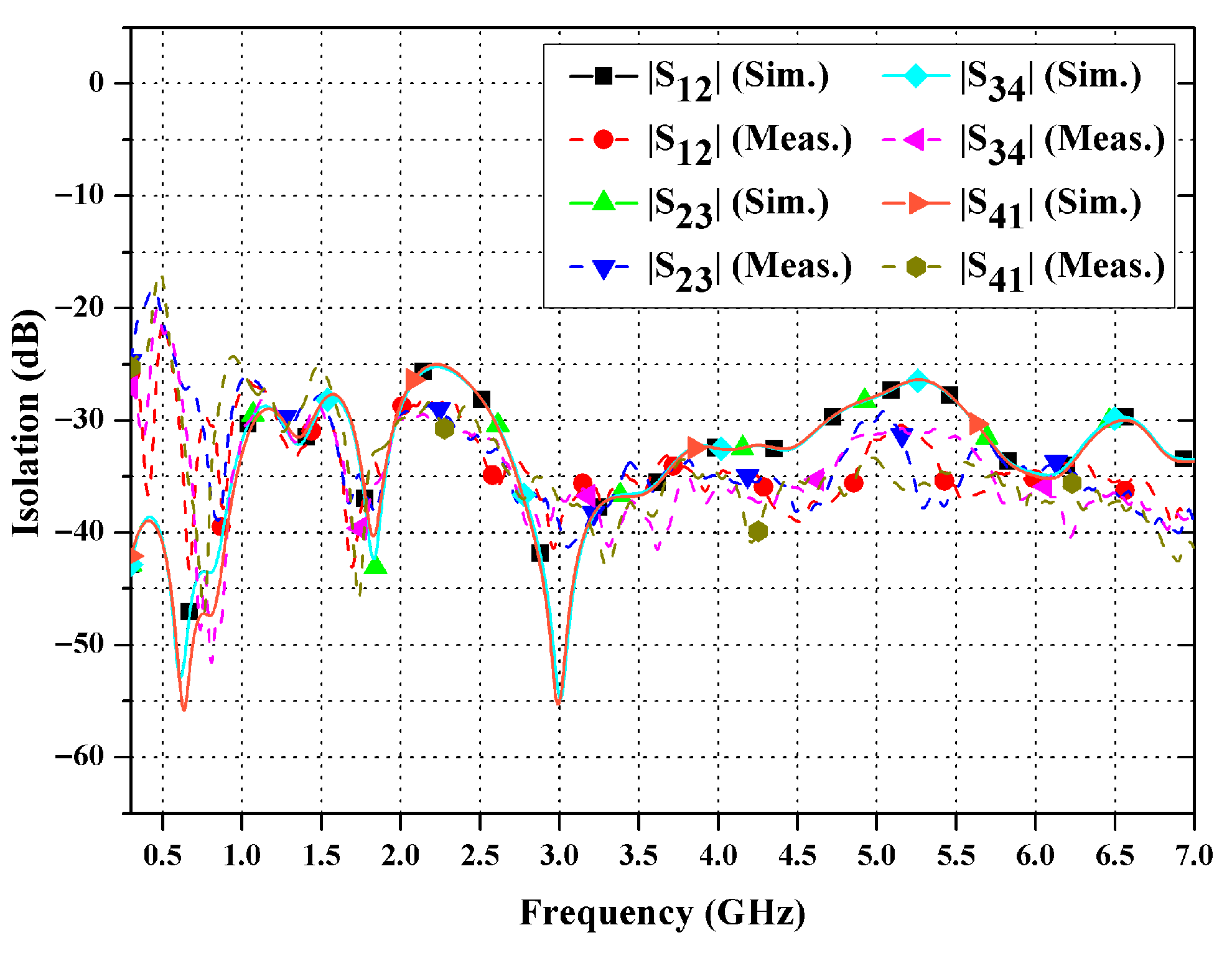
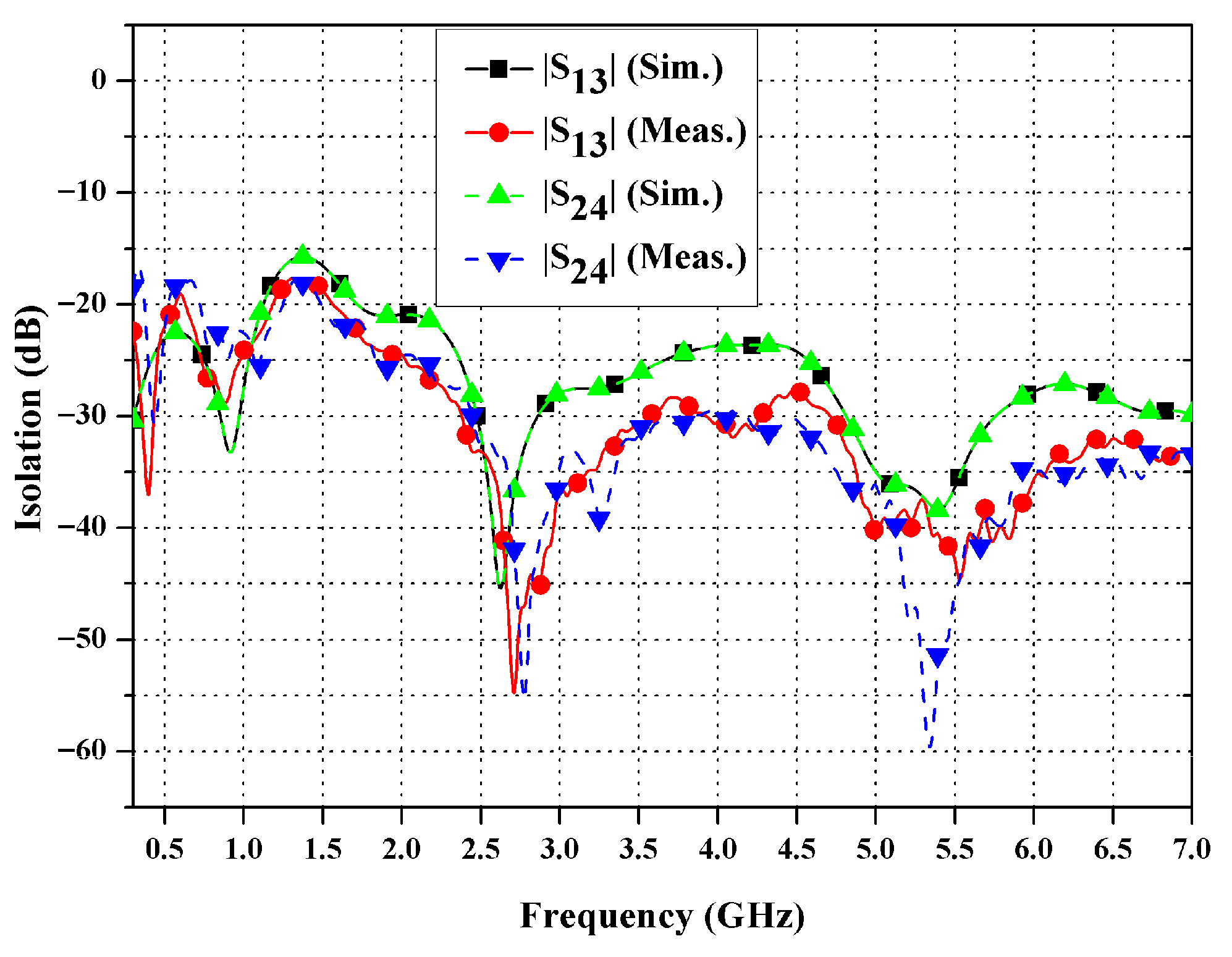
Figure 21 and Figure 22 show the port isolation characteristics (|S12|, |S23|, |S34|, |S41|, |S13|, and |S24|) for both the simulated and measured data. Throughout the operational frequency ranges, all isolation levels surpass 15 dB, with maxima exceeding 50 dB observed in proximity to resonances. The isolation between adjacent ports remains above 25 dB, as a result of both symmetric spacing and field cancelation effects; diagonal port pairs (|S13|, |S24|) are further aided by orthogonal polarization. The strong agreement between the simulated and measured data validates the resilience of the embedded decoupling structures to fabrication-related variations.

4.2. Radiation Pattern

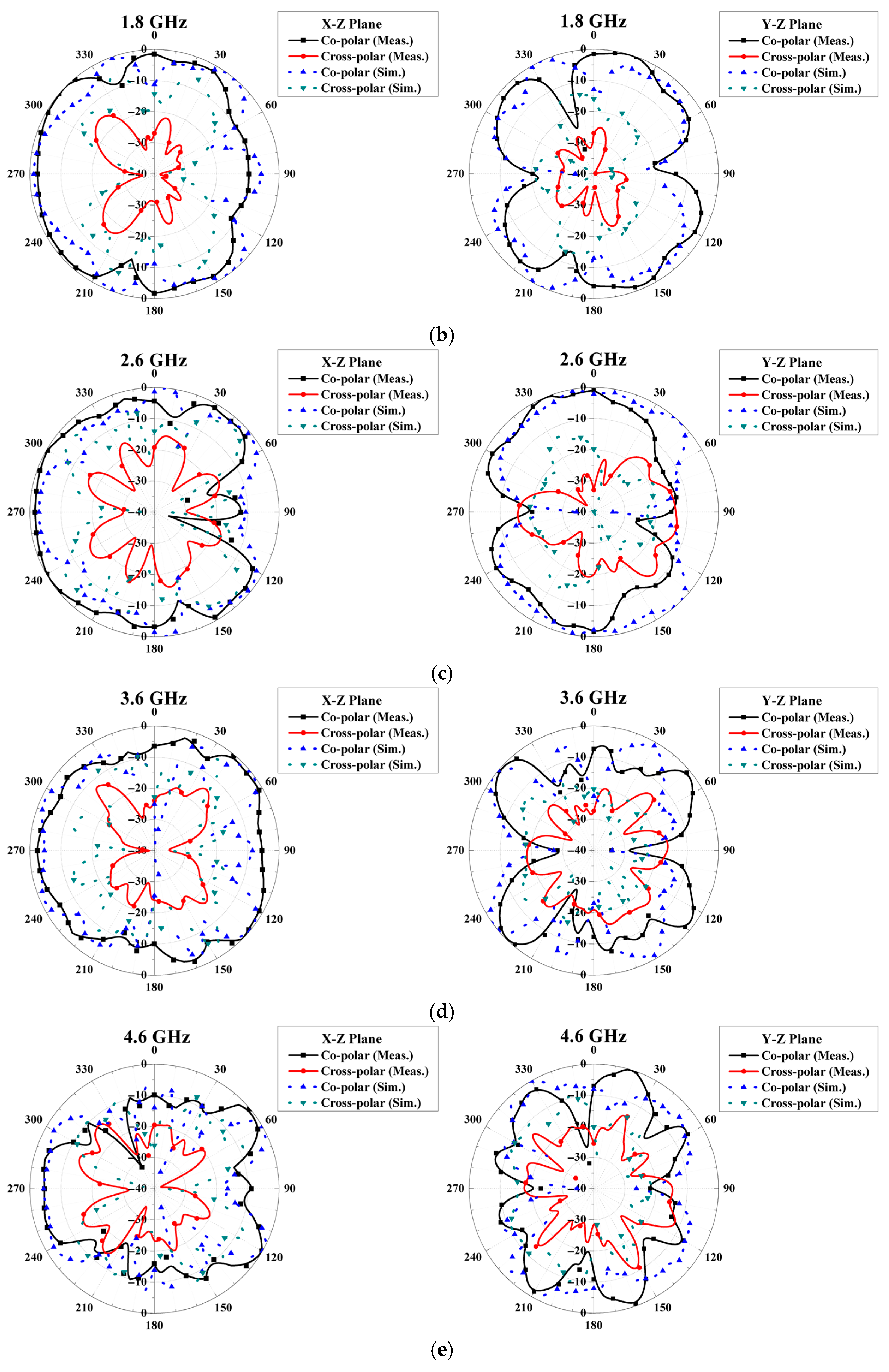
Figure 23 illustrates the measured and simulated radiation patterns in the XZ (H-plane) and YZ (E-plane) planes for Port 1 at key frequencies of 0.7, 1.8, 2.6, 3.6, and 4.6 GHz. The coverage is almost omnidirectional throughout the frequency spectrum. The half-power beamwidth (HPBW) is about 75° at lower frequencies, particularly between 0.7 and 1.8 GHz, while the value diminishes to 15° at 4.6 GHz. The front-to-back (F/B) ratio is consistently constant and stable at 0–0.1 dB. Additionally, the cross-polarization values typically range between −8 dB and −25 dB. Table 3 provides a detailed summary of the radiation properties at the key frequencies.
The observed results show a small difference between the simulated and measured data (less than 3 dB in the envelope), confirming the accuracy of the manufacturing process. The change in beamwidth indicates a shift from radiation patterns similar to a monopole at lower frequencies to a more focused, array-like pattern at frequencies above 3 GHz. This is consistent with D1 = 90 mm, which is 0.21λ0 at 0.7 GHz and increases to 1.38λ0 at 4.6 GHz.

4.3. Gain and Efficiency

The measured gain of the constructed four-port MIMO antenna prototype was evaluated in an anechoic chamber employing the gain-transfer method with a typical horn antenna as a reference, confirming its wideband radiation efficiency over the 0.3–7 GHz range to validate its suitability for sub-6 GHz 5G applications.
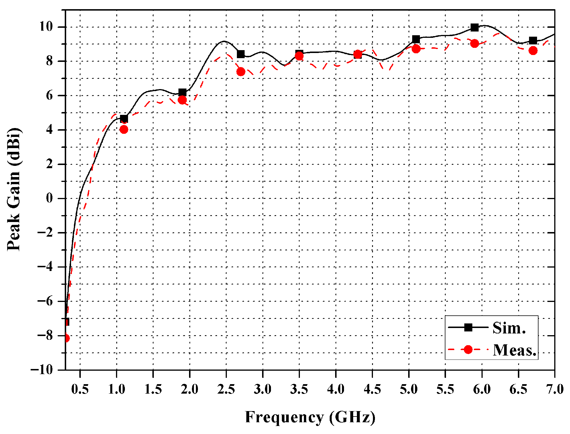
Figure 24 compares the simulated and measured peak gains against frequency, demonstrating a strong correlation with deviations below 1 dBi, which may be ascribed to material losses, SMA connection effects, and fabrication tolerances. The observed peak gain ranges from 2.1 dBi at lower frequencies to a high of 10 dBi around 6 GHz, consistently exceeding 4 dBi over much of the spectrum with stable performance (between 8 and 10 dBi) in the 2.2–7 GHz range. Minor reductions at 0.7 GHz and 1.2 GHz indicate impedance transition sites, although they remain above 3 dBi, indicating stable radiation efficiency with minimal fluctuation and, thus, suitability for MIMO diversity in multipath environments.
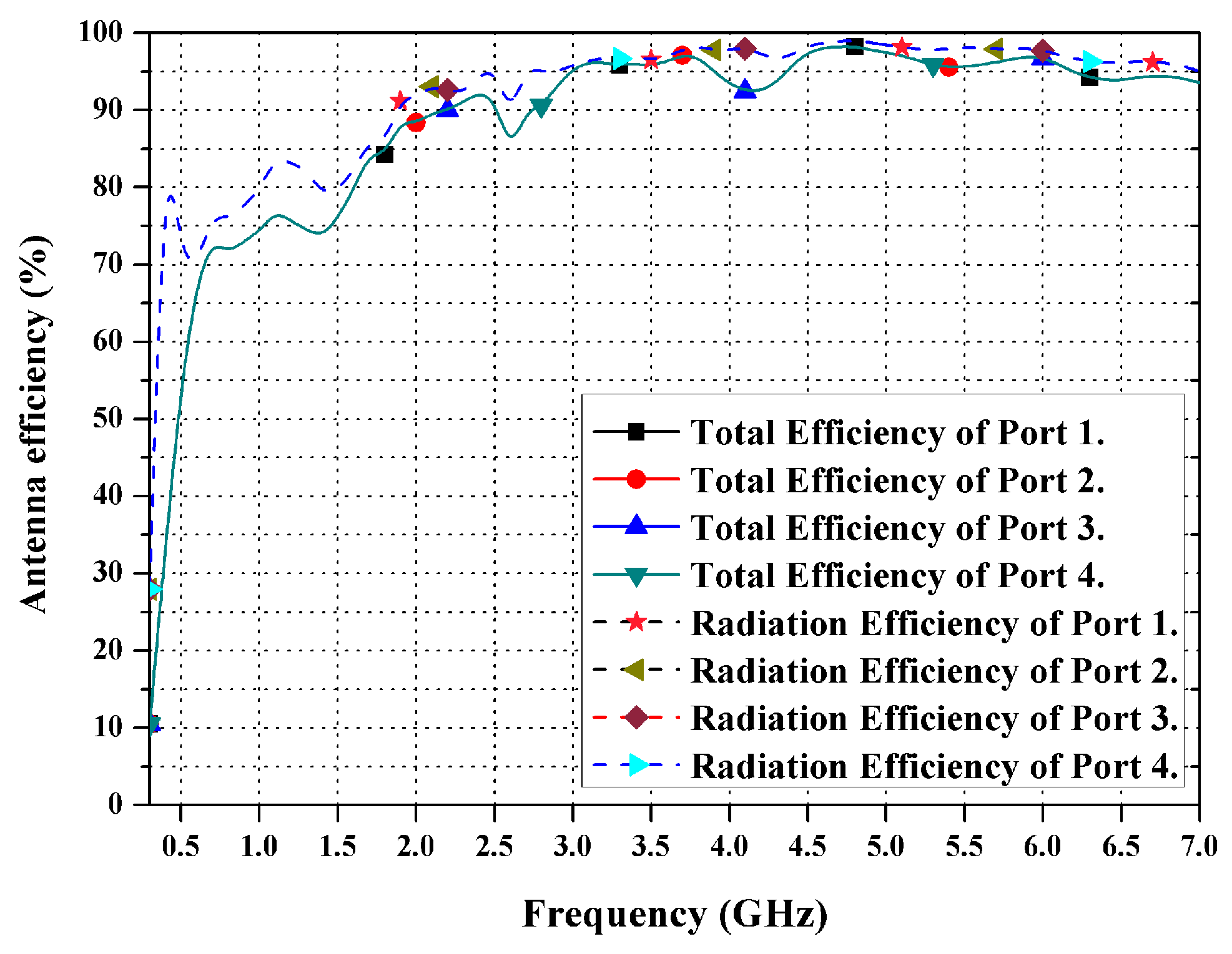
As can be seen from Figure 25, in terms of radiation and total efficiency, robust wideband performance was demonstrated on the polycarbonate substrate. Radiation efficiency monotonically improved from 75% (0.7 GHz) to 98% (4.6 GHz), exceeding 85% above 1.8 GHz despite low-frequency challenges. Total efficiency (including mismatch) remained >72% across the band, correlating with Sii < −10 dB. The minimal radiation efficiency variation (<23%) vs. frequency confirms multi-mode resonance in the modified circular patches and triangular grounds. Polycarbonate with a tan δ of 0.005448 exhibits dielectric losses below 2%, outperforming FR4 alternatives. This design does not require EBG or metamaterials, distinguishing it from compact designs that suffer from hand-effect degradation. The efficiency metrics shown in Table 3 confirm the proposed antenna’s practical utility in high-throughput infrastructure applications.
Table 4 indicates that the majority of compared broadband and UWB MIMO antennas operate below 6 GHz (approximately 3–8 GHz), exhibit separation values of approximately 15–25 dB, and frequently employ explicit separation networks, parasitic elements, or metamaterial-inspired configurations to mitigate coupling. Specifically, compact designs ([17,21,23,36,48,49]: 0.2–0.85λ0, Iso/spac. >52–188 dB/λ) rely on metamaterials/DGSs, unlike the proposed intrinsic orthogonal decoupling. The proposed four-port array features modified circular patches integrated into a triangular ground plane, arranged perpendicularly at the four corners of a polycarbonate substrate (elec. size 1.17λ0 × 1.17λ0). This facilitates continuous operation within the 0.7–7 GHz range (FBW ≈ 163.63%) while ensuring separation values exceeding 15 dB over the bandwidth (>71.43 dB/λ) with a measured peak exceeding 50 dB, all of which is achieved without the need for supplementary separation elements. This is accompanied by exceedingly low ECC (<0.008), TARC below −10 dB, balanced MEG (about −3 dB), and nearly constant group delay. The findings indicate that the unique combination of the modified spherical disperser, the triangular ground design, and the perpendicular symmetrical configuration is crucial for the antenna’s optimal operation. This study presents a different architectural approach, yielding broadband MIMO performance and enhanced signal separation, which are not observed in comparable advanced systems with superior normalized metrics (Iso/spac. ratio > 71.43 dB/λ, gain/elec. size 8.6 dBi/λ2) despite a larger aperture intended for base station applications.

5. Conclusions

This research presented a four-port wideband MIMO antenna array fabricated on a polycarbonate substrate (εr = 2.8, tan δ = 0.005448, h = 1 mm) with dimensions of 500 × 500 mm2. The simulation and measurement outcomes successfully demonstrated the achievement of the proposed design objectives across all ports, encompassing sub-6 GHz 5G (n78/n79), LTE, IoT, and radar frequencies. Critical metrics include isolation above 15 dB (with a peak at around 50 dB), ECC below 0.008, TARC less than −10 dB (multi-phase), balanced MEG around −3 dB (XPR = 0/6 dB), and group delays of approximately 0.5 ns (with a variance of ±0.75 ns).
Orthogonal modified circular patches with triangular bases at a spacing of D1 = 90 mm offer intrinsic isolation without the need for metamaterials, DGSs, or decoupling networks, with surface currents at 0.7, 1.8, 2.6, 3.6, and 4.6 GHz exhibiting confinement to energized elements. The peak gain is 10 dBi with omnidirectional patterns, as confirmed through simulations using CST Microwave Studio 2025.
The suggested antenna is designed for use in extensive applications that require ample panel space, such as sub-6 GHz 5G base station panels, wall- or ceiling-mounted access points, radar/IoT hubs, and MIMO testbeds. Its 500 × 500 mm2 aperture optimally combines dimensions and performance for 0.7–7 GHz coverage, providing exceptional isolation and diversity. Compact narrowband MIMO is more appropriate for space-constrained devices such as smartphones, while this architecture is expected to shine in high-throughput infrastructure systems.
Future research will encompass metasurface-driven miniaturization, sub-6/mm. Wave hybrid systems, and multi-user 5G field experiments.

Author Contributions

Conceptualization, P.R., C.M., N.W., and W.C.; data curation, P.R., C.M., N.W., and N.T.; formal analysis, P.R., C.M., N.W., P.S., and S.K.; funding acquisition, P.R., C.M., N.W., and P.A.; investigation, P.R., C.M., N.W., W.C., and N.T.; methodology, P.R., C.M., N.W., and P.S.; software, P.R., C.M., N.W., P.S., and S.K.; supervision, P.R. and C.M.; validation, P.R., C.M., and N.W.; writing—original draft, P.R., C.M., and N.W.; writing—review and editing, P.R., C.M., and N.W. All authors have read and agreed to the published version of the manuscript.

Funding

This research was supported by the National Science, Research and Innovation Fund, Thailand Science Research and Innovation (TSRI), through Rajamangala University of Technology Thanyaburi (FRB69E0712) (Grant No.: FRB690069/0168) and King Mongkut’s University of Technology North Bangkok, with Contract No. KMUTNB-FF-69-A-01.

Data Availability Statement

This research includes the original contributions offered in the article. Additional queries may be sent to the corresponding author.

Acknowledgments

The authors would like to express their sincere gratitude to the Department of Electronics and Telecommunication Engineering, Faculty of Engineering, Rajamangala University of Technology Thanyaburi, for their technical and experimental support. The authors also acknowledge the use of the CST Microwave Studio software provided by the respective institutions for antenna simulation.

Conflicts of Interest

The authors declare no conflicts of interest.

References

  1. Parchin, N.O.; Basherlou, J.H.; Al-Yasir, Y.I.A.; Ullah, A.; Abd-Alhameed, R.A.; Noras, J.M. Multi-Band MIMO Antenna Design with User-Impact Investigation for 4G and 5G Mobile Terminals. Sensors 2019, 19, 456. [Google Scholar]
  2. Chutchavong, V.; Chanwattanapong, W.; Wongsin, N.; Rakluea, P.; Tangjitjetsada, M.; Rakluea, C.; Mahatthanajatuphat, C.; Akkaraekthalin, P. A Flexible and Compact UWB MIMO Antenna with Dual-Band-Notched Double U-Shaped Slot on Mylar® Polyester Film. Electronics 2025, 14, 3363. [Google Scholar] [CrossRef]
  3. Malviya, L.; Kumar, P.R.; Kartikeyan, M. Four-element planar MIMO antenna design for long-term evolution operation. IETE J. Res. 2018, 64, 367–373. [Google Scholar] [CrossRef]
  4. Srivastava, G.; Dwari, S.; Kanuijia, B. A compact 4 × 4 ultrawideband (UWB) band notched MIMO antenna. In Proceedings of the IEEE International Microwave and RF Conference (IMaRC), Bangalore, India, 15–17 December 2014; pp. 198–200. [Google Scholar]
  5. Soltani, S.; Murch, R. A compact planar printed MIMO antenna design. IEEE Trans. Antennas Propag. 2015, 63, 1140–1149. [Google Scholar] [CrossRef]
  6. Lu, W.K.; Hsuan, S.C.; Ting, L.W.; Yu, L.W. Ultra-Wideband On-Metal Four-Antenna Module for 5G/6G/WiFi-6E IoT Mobile Device MIMO Antennas and Its Field Test Study. IEEE Access 2024, 12, 166349–166367. [Google Scholar]
  7. Tang, Z.; Wu, X.; Zhan, J.; Hu, S.; Xi, Z.; Liu, Y. Compact UWB-MIMO Antenna with High Isolation and Triple Band-Notched Characteristics. IEEE Access 2019, 7, 19856–19865. [Google Scholar] [CrossRef]
  8. Desai, A.; Kulkarni, J.; Kamruzzaman, M.; Hubálovský, Š.; Tung, H.H.; Ibrahim, A. Interconnected CPW Fed Flexible 4-Port MIMO Antenna for UWB, X, and Ku Band Applications. IEEE Access 2022, 10, 57641–57654. [Google Scholar] [CrossRef]
  9. Desai, A.; Tung, H.H.; Yousef, B.; Ameen, A.; Fan, T.Y.; Ibrahim, A. UWB Connected Ground Transparent 4-Port Flexible MIMO Antenna for IoT Applications. IEEE Internet Things J. 2024, 11, 12475–12484. [Google Scholar] [CrossRef]
  10. Rajesh, G.; Poonkuzhali, R. Design and Analysis of CPW Fed Ultrathin Flexible MIMO Antenna for UWB and X-Band Applications. IEEE Access 2024, 12, 96704–96717. [Google Scholar] [CrossRef]
  11. Gómez, V.R.; Jardón, A.H. Compact UWB Uniplanar Four-Port MIMO Antenna Array with Rejecting Band. IEEE Antennas Wirel. Propag. Lett. 2019, 18, 2543–2547. [Google Scholar] [CrossRef]
  12. Al, S.H.; Usman, M.; Tajammal, C.M.; Nasir, J. Compact Ultra Wideband MIMO Antenna System for Lower 5G Bands. Wireless Commun. Mobile Comput. 2018, 2018, 2396873. [Google Scholar]
  13. Zou, X.J.; Wang, Y.W.; Zong, B.F.; Xu, X.G.; Han, L.X.; Zhu, H.; Song, W.; Tan, M.; Du, H.N. Miniaturized Low-Profile Ultrawideband Antipodal Vivaldi Antenna Array Loaded with Edge Techniques. IEEE Trans. Antennas Propag. 2026, 74, 1156–1161. [Google Scholar] [CrossRef]
  14. Zhu, N.; Zhang, Y.; Zhao, Z.; Meng, F. Design of a Compact Wideband SPDT Switch With High Isolation for Sub-6 GHz Applications. IEEE Trans. Circuits Syst. II Express Briefs 2026, 73, 43–47. [Google Scholar] [CrossRef]
  15. Ting, Y.X.; He, W.; Dong, H.K.; Zhe, C.; Chen, Z.; Yuan, T. Ultra Wideband MIMO Antenna System with High Element-Isolation for 5G Smartphone Application. IEEE Access 2020, 8, 56281–56289. [Google Scholar] [CrossRef]
  16. Chen, Z.; Ting, Y.X.; Ren, J.; Yuan, T. An Ultra-Wideband MIMO Antenna for 5G Smartphone. AEU-Int. J. Electron. Commun. 2022, 154, 154301. [Google Scholar] [CrossRef]
  17. Parchin, O.N.; Ismael, Y.A.A.I.Y.; Ali, A. Eight-Element Dual-Polarized MIMO Slot Antenna System for 5G Smartphone Applications. IEEE Access 2019, 7, 15612–15622. [Google Scholar] [CrossRef]
  18. Ko, S.; Murch, R. Compact Integrated Diversity Antenna for Wireless Communications. IEEE Trans. Antennas Propag. 2021, 49, 954–960. [Google Scholar] [CrossRef]
  19. Desai, A.; Danh, B.C.; Patel, J.; Upadhyaya, T.; Byun, G.; Khang, N.T. Compact Wideband Four-Element Optically Transparent MIMO Antenna for mm-wave 5G Applications. IEEE Access 2020, 8, 194206–194217. [Google Scholar] [CrossRef]
  20. Sakli, H.; Abdelhamid, C.; Essid, C.; Sakli, N. Metamaterial-Based Antenna Performance Enhancement for MIMO System Applications. IEEE Access 2021, 9, 38546–38556. [Google Scholar] [CrossRef]
  21. Nirmal, P.; Nandgaonkar, A.; Nalbalwar, S.; Gupta, R. A Compact Dual Band MIMO Antenna with Improved Isolation for Wi-Max and WLAN Applications. Prog. Electromagn. Res. M. 2018, 68, 69–77. [Google Scholar] [CrossRef]
  22. Kulkarni, N.P.; Bahadure, N.B.; Patil, P.D.; Karve, S.M.; Kulkarni, J.S.; Kadam, S.S. Flexible MIMO Antennas for 5G Applications. In Proceedings of the 2022 10th International Conference on Emerging Trends in Engineering and Technology—Signal and Information Processing (ICETET-SIP-22), Nagpur, India, 29–30 April 2022; pp. 1–6. [Google Scholar]
  23. Ghadeer, S.H.; Rahim, S.K.; Alibakhshikenari, M.; Virdee, B.S.; Elwi, T.A.; Iqbal, A.; Al-Hasan, M. An Innovative Fractal Monopole MIMO Antenna for Modern 5G Applications. AEU- Int. J. Electron. Commun. 2023, 159, 154480. [Google Scholar] [CrossRef]
  24. Yang, Y.; Mao, M.; Xu, J.; Liu, H.; Wang, J.; Song, K. Millimeter-Wave Antennas for 5G Wireless Communications: Technologies, Challenges, and Future Trends. Sensors 2025, 25, 5424. [Google Scholar] [CrossRef] [PubMed]
  25. Al, A.E.; Ikram, M.; Toaha, M.A.; Abbosh, A. MIMO Antenna System for Multi-Band Millimeter-Wave 5G and Wideband 4G Mobile Communications. IEEE Access 2019, 7, 181916–181923. [Google Scholar]
  26. Tariq, S.; Naqvi, S.; Hussain, N.; Amin, Y. A Metasurface-Based MIMO Antenna for 5G Millimeter-Wave Applications. IEEE Access 2021, 9, 51805–51817. [Google Scholar] [CrossRef]
  27. Hussain, N.; Joo, J.M.; Abbas, A.; Kim, N. Metasurface-Based Single-Layer Wideband Circularly Polarized MIMO Antenna for 5G Millimeter-Wave Systems. IEEE Access 2020, 8, 130293–130304. [Google Scholar] [CrossRef]
  28. Usman, M.; Kobal, E.; Nasir, J.; Zhu, Y.; Yu, C.; Zhu, A. Compact SIW Fed Dual-Port Single Element Annular Slot MIMO Antenna for 5G mmWave Applications. IEEE Access 2021, 9, 91995–92002. [Google Scholar] [CrossRef]
  29. Ahmad, J.; Hashmi, M. Reduced Inter-Element Interference mmWave MIMO Antenna and Its Application in WBAN. IEEE Access 2025, 13, 70947–70963. [Google Scholar] [CrossRef]
  30. Gao, X.; Dai, L.; Han, S.; Wang, Z.; Heath, R. Energy-Efficient Hybrid Analog and Digital Precoding for mmWave MIMO Systems with Large Antenna Arrays. IEEE J. Sel. Areas Commun. 2016, 34, 998–1009. [Google Scholar] [CrossRef]
  31. Ayaz, M.; Ullaha, I.; Iftikhar, A.; Muzahir, A.S.; Braaten, B. Flexible Conformal Phased Array with Embedded Magnetic Particles Based Composite Right/Left Handed Metamaterial Phase Shifters. IEEE Access 2024, 12, 129147–129159. [Google Scholar] [CrossRef]
  32. Chen, X.; Li, K. Ultrathin and Flexible Ultrawideband Antenna Array Based on Integrated Impedance Matching Line. IEEE Antennas Wirel. Propag. Lett. 2023, 22, 960–964. [Google Scholar] [CrossRef]
  33. Desai, A.; Palandoken, M.; Kulkarni, J.; Byun, G.; Khang, N.T. Wideband Flexible/Transparent Connected-Ground MIMO Antennas for Sub-6 GHz 5G and WLAN Applications. IEEE Access 2021, 9, 147003–147015. [Google Scholar] [CrossRef]
  34. Abdelrahman, E.H.; Himdi, M.; Castel, X.; Kamal, R.A.S.; Kim, G.T. Flexible Patch Antenna Array Operating at Microwaves Based on Thin Composite Material. IEEE Access 2022, 10, 115663–115672. [Google Scholar] [CrossRef]
  35. Alqadami, A.; Stancombe, A.; Bialkowski, K.; Abbosh, A. Flexible Meander-Line Antenna Array for Wearable Electromagnetic Head Imaging. IEEE Trans. Antennas Propag. 2021, 69, 4206–4211. [Google Scholar] [CrossRef]
  36. Aggarwal, I.; Pandey, S.; Tripathy, M.R.; Mittal, A. Design and Analysis of Metamaterial-Based SWB-MIMO antenna. IETE J. Res. 2023, 69, 6733–6746. [Google Scholar] [CrossRef]
  37. Aspe, B.; Castel, X.; Demange, V.; Députier, S.; Bouquet, V.; Benzerga, R.; Sauleau, R.; Guilloux, V.M. Frequency-Tunable Slot-loop Antenna Based on KNN Ferro Electric Interdigitated Varactors. IEEE Antennas Wireless Propag. Lett. 2021, 20, 1414–1418. [Google Scholar] [CrossRef]
  38. Dattatreya, G.; Appala, R.V.; Dabbakuti, K. DGS based monopole circular-shaped patch antenna for UWB applications. SN Appl. Sci. 2021, 3, 198. [Google Scholar] [CrossRef]
  39. Tiwari, P.; Kaushik, M.; Shastri, A.; Kumar, R.J.; Gahlaut, V. Simulated Design and Analysis of Highly Isolated 5G Millimeter-Waves MIMO Antenna with Wideband Characteristic. In Proceedings of the IEEE First International Conference on Microwave, Antenna and Communication (MAC), Prayagraj, India, 24–26 March 2023; pp. 1–6. [Google Scholar]
  40. Ali, W.; Ibrahim, A. A compact double-sided MIMO antenna with an improved isolation for UWB applications. AEU- Int. J. Electron. Commun. 2017, 82, 7–13. [Google Scholar] [CrossRef]
  41. Patil, A.; Bhadade, R. A Literature Survey on MIMO Antenna. In Proceedings of the International Conference on IoT Based Control Networks and Intelligent Systems ICICNIS 2021, Kerala, India, 28–29 June 2021; pp. 1–8. [Google Scholar]
  42. Deng, J.; Li, J.; Zhao, L.; Guo, L. A Dual-Band Inverted-F MIMO Antenna with Enhanced Isolation for WLAN Applications. IEEE Antennas Wirel. Propag. Lett. 2017, 16, 2270–2273. [Google Scholar] [CrossRef]
  43. Sharawi, M. Printed Multi-Band MIMO Antenna Systems and Their Performance Metrics [Wireless Corner]. IEEE Antennas Propag. Mag. 2013, 55, 218–232. [Google Scholar] [CrossRef]
  44. IEEE Std 149-2021; IEEE Recommended Practice for Antenna Measurements. IEEE: New York, NY, USA, 2021.
  45. ETSI. Study on Channel Model for Frequencies from 0.5 to 100 GHz; 3GPP TR 38.901 V17.0.0; ETSI: Brooklyn, NY, USA, 2022. [Google Scholar]
  46. Taga, T. Analysis for Mean Effective Gain of Mobile Antennas in Land Mobile Radio Environments. IEEE Trans. Veh. Technol. 1990, 39, 117–131. [Google Scholar] [CrossRef]
  47. Sharawi, M. Current Misuses and Future Prospects for Printed Multiple-Input, Multiple-Output Antenna Systems [Wireless Corner]. IEEE Antennas Propag. Mag. 2017, 59, 162–170. [Google Scholar] [CrossRef]
  48. Fahmida, H.; Mohd, K.B.N.; Zakir, H.; Nurulhalim, B.H. A Double-Slotted Microstrip Rectangular 6 × 6 Array for Sub-6 GHz Wireless Applications. Int. J. Electr. Electron. Eng. 2024, 11, 107–118. [Google Scholar]
  49. Zakir, H.; Muhammad, I.I.; Mohd, K.B.N.; Abdul, H.B.D. Design and Validation of a 6-Port Planar MIMO Array for Sub-6 GHz 5G Bands. Int. J. Electr. Electron. Eng. 2024, 11, 71–82. [Google Scholar] [CrossRef]
  50. Ibrahim, A.M.; Ibrahim, I.M.; Shairi, N.A. Compact MIMO Antenna with High Isolation for 5G Smartphone Applications. J. Eng. Sci. Technol. Rev. 2019, 12, 121–125. [Google Scholar] [CrossRef]
  51. Cuneray, K.; Akcam, N.; Okan, T. 28/38 GHz Dual-Band MIMO Antenna with Wideband and High Gain Properties for 5G Applications. AEU-Int. J. Electron. Commun. 2023, 162, 154553. [Google Scholar] [CrossRef]
  52. Atuwayr, A.; Asmeida, A.; Abdelmula, H.S.B.A.; Anaiba, A.A. Optimization of MIMO Antenna Approach for 5G Wireless Applications. In Proceedings of the 2023 IEEE 11th International Conference on Systems and Control (ICSC), Sousse, Tunisia, 18–20 December 2023; pp. 647–653. [Google Scholar]
  53. Kin-Lu, W.; Yu-Hao, H.; Cheng-Yu, L.; Wei-Yu, L. Wideband 4-Port Patch Antenna Module Based Compact 8-Port Two-Module Antenna for 6G Upper Mid-Band 8 × 4 Device MIMO with Enhanced Spectral Efficiency. IEEE Access 2024, 12, 88976–88991. [Google Scholar]
Figure 1. Measurement of dielectric constant (εr = 2.8) and loss tangent (tan δ = 0.005448) of the polycarbonate substrate using an Agilent 85072A Split Cylinder Resonator.
Electronics 15 01466 g001
Figure 2. Single-element wideband antenna evolution: (a) conventional monopole (Ant. I); (b) modified circular monopole (Ant. II); (c) modified circular monopole with triangular ground (Ant. III).
Electronics 15 01466 g002
Figure 3. Simulated |S11| comparison of single-element prototypes (Ant. I–III) across 0.3–7 GHz.
Electronics 15 01466 g003
Figure 4. Proposed four-port MIMO antenna: four-fold rotational symmetry with 90° orthogonal modified circular patches and triangular grounds at substrate corners.
Electronics 15 01466 g004
Figure 5. Simulated |S11| (dB) of single-element antenna vs. patch radius of R1 = 64.4, 74.4, and 84.4 mm over 0.3–7 GHz.
Electronics 15 01466 g005
Figure 6. Computed |S11| of single-element antenna vs. frequency (0.3–7 GHz) for g1 = 0.3, 1.3, and 2.3 mm.
Electronics 15 01466 g006
Figure 7. Simulated |S11| of the single-element antenna vs. ground widths of Wg = 89.3, 99.3, and 109.3 mm over 0.3–7 GHz.
Electronics 15 01466 g007
Figure 8. Simulated |S12| for the four-port MIMO antenna with D1 = 70, 90, and 110 mm over 0.3–7 GHz.
Electronics 15 01466 g008
Figure 9. Simulated |S11| (dB) for the four-port MIMO antenna with D1 = 70, 90, and 110 mm over 0.3–7 GHz.
Electronics 15 01466 g009
Figure 10. Simulated |Sii| (dB) for all four ports (i = 1–4) of the proposed MIMO antenna over 0.3–7 GHz.
Electronics 15 01466 g010
Figure 11. Simulated |Sij| (dB) for adjacent ports (S12, S23, S34, and S41; in a 90° configuration) of the proposed MIMO antenna over 0.3–7 GHz.
Electronics 15 01466 g011
Figure 12. Simulated |Sij| (dB) for opposite ports (S13, S24; in a 180° configuration) of the proposed MIMO antenna over 0.3–7 GHz.
Electronics 15 01466 g012
Figure 13. Simulated TARC (dB) of the proposed four-port MIMO antenna over 0.7–7 GHz for (a) primary phase configurations and (b) additional phase configurations.
Electronics 15 01466 g013
Figure 14. Simulated MEG (dB) of the proposed four-port MIMO antenna over 0.7–7 GHz: (a) single-port MEG under XPR = 0 dB and XPR = 6 dB; and (b) pairwise MEG comparisons under XPR = 6 dB.
Electronics 15 01466 g014
Figure 15. Simulated ECC of the proposed four-port wideband MIMO antenna for all port pairs over 0.7–7 GHz.
Electronics 15 01466 g015
Figure 16. Simulated group delay of the proposed four-port wideband MIMO antenna for all port pairs over 0.7–7 GHz.
Electronics 15 01466 g016
Figure 17. Simulated surface current distribution of the proposed four-port wideband MIMO antenna when port 1 is excited at (a) 0.7 GHz, (b) 1.8 GHz, (c) 2.6 GHz, (d) 3.6 GHz, and (e) 4.6 GHz.
Electronics 15 01466 g017aElectronics 15 01466 g017b
Figure 18. Simulated surface current distribution of the proposed four-port wideband MIMO antenna when port 2 is excited at (a) 0.7 GHz, (b) 1.8 GHz, (c) 2.6 GHz, (d) 3.6 GHz, and (e) 4.6 GHz.
Electronics 15 01466 g018aElectronics 15 01466 g018b
Figure 19. Photographs and dimensional layout of the four-port wideband MIMO antenna prototype for sub-6 GHz 5G applications, fabricated on a polycarbonate substrate: (a) length view and (b) width view.
Electronics 15 01466 g019
Figure 20. Simulated and measured |S11|, |S22|, |S33|, and |S44| of the proposed MIMO antenna over 0.3–7 GHz.
Electronics 15 01466 g020
Figure 21. Simulated and measured |S12|, |S23|, |S34|, and |S41| of the proposed MIMO antenna arranged at 90 degrees over 0.3–7 GHz.
Electronics 15 01466 g021
Figure 22. Simulated and measured |S13| and |S24| of the proposed MIMO antenna arranged at 180 degrees over 0.3–7 GHz.
Electronics 15 01466 g022
Figure 23. Measured and simulated radiation patterns of the proposed antenna in the XZ (H-plane) and Y–Z (E-plane) planes at (a) 0.7 GHz, (b) 1.8 GHz, (c) 2.6 GHz, (d) 3.6 GHz, and (e) 4.6 GHz.
Electronics 15 01466 g023aElectronics 15 01466 g023b
Figure 24. Simulated and measured peak gain of the proposed antenna over 0.3–7 GHz.
Electronics 15 01466 g024
Figure 25. Simulated radiation and total efficiency vs. frequency (0.3–7 GHz) at all ports.
Electronics 15 01466 g025
Table 1. Key geometric parameters of the proposed wideband four-port MIMO antenna array.
ParameterDimension Size (mm)ParameterDimension Size (mm)ParameterDimension Size (mm)
W210Lg79Ls20.2
L200R174.4Wm500
Wf10g11.3Lm500
Wg99.3Lp154.5D190
g0.7Ws29.3
Table 2. Port isolation performance summary.
Port PairTypeMin.
(dB)
Peak
(dB)
Coverage (>25 dB)Frequency Range (GHz)
S12, S23, S34, S41Adjacent (90°)2555 100%0.7–7
S13, S24Opposite (180°)154563.5%0.7–7
All SijOverall155563.5%0.7–7
Table 3. Summary of radiation characteristics across key frequencies.
Frequency (GHz)Efficiency (%)HPBW (Degree)F/B (dB)Cross-Polar. (dB)Gain (dBi)
X-Z PlaneY-Z PlaneX-Z PlaneY-Z PlaneX-Z PlaneY-Z Plane
0.784.13300.698.300.01−19.43−23.042.15
1.890.35120.175.60.020.02−11.6−14.416.13
2.690.53100.770.600.01−12.02−24.558.92
3.696.5960.020.30.10.01−13.87−12.888.52
4.697.4740.415.40.10.1−8.57−14.468.03
Table 4. Comparison of the significant characteristics of the proposed antenna and previously reported MIMO antennas.
Ref.Element no,
Material,
Isolation Tech.
Dimensions
(mm2)
Frequency (GHz), Bandwidth (%),
Application
Isolation
(dB),
Iso/spac. Ratio (dB/λ),
ECC
Peak Gain
(dBi),
Gain/elec. Size Ratio (dB/λ2), Rad. Eff. (%)
[13]8 × 8, FR-4,
AVA
156 × 156 × 61,
(0.47λ0 × 0.47λ0 × 0.18λ0)
0.9–12, (172%),
UWB phased arrays
N/A,
N/A
N/A
3–25, 9.5–31.5
>70%
[17]2 × 2, FR-4,
Metamaterials
75 × 150,
(0.85λ0 × 1.7λ0)
3.4–3.8, (11%),
Smartphone
>15,
>52
<0.05
4,
2.4
N/A
[21]2 × 1, FR-4, Elliptical slot, parasitic elements30 × 26,
(0.32λ0 × 0.28λ0)
3.2–3.8, (17%)
and 5.7–6.2, (8.4%),
Portable devices
>20,
>188
<0.05
1.5/2.8, 11.9/13.2
N/A
[23]2 × 2, FR-4, Fractal30 × 40,
(0.2λ0 × 0.27λ0)
2–3, (40%),
3.4–3.9, (13.7%),
and 4.4–5.2, (16.67%),
Smartphone
>20,
N/A
N/A
5,
17.6
N/A
[36]2 × 2, FR-4, Metamaterials50 × 50 × 30.5,
(0.68λ0 × 0.68λ0 × 0.42λ0)
4.1–14.7, (112%),
Radar systems
>15,
>35
N/A
7.2,
10.5
N/A
[50]2 × 1, FR-4, Fractal21 × 24,
(0.33λ0 × 0.38λ0)
4.7–5, (6.1%),
Smartphone
>18.5, N/A,
N/A
N/A,
N/A,
N/A
[51]2 × 2, FR-4, DGS+slot and branches60 × 60,
(5.47λ0 × 5.47λ0)
27.35–30.40, (10.89%) and 36.98–39.39, (6.36%),
5G mmWave
>25,
N/A
N/A
8.1,
6.6,
N/A
[52]2 × 2, FR-4, Metamaterial + DGS94 × 120.2,
(1.82λ0 × 2.32λ0)
5.8, (4.3%),
WLAN
>20,
>114.9
N/A
6.1,
−0.2
N/A
[48]6 × 6, RT-5880, PGP+double slot75 × 150,
(0.77λ0 × 1.55λ0)
3.1–4.53, (37.5%),
Smartphone
>16.6, >17.84
<0.004
5.4,
4.6
80%
[53]8 × 4, FR-4, shorting metal wall27.5 × 58,
(0.59λ0 × 1.24λ0)
6.425–8.4, (29.3%),
Smartphone/IoT
>10,
>155
<0.02
N/A, N/A
46–54%
[49]6×6, RT-5880, Partial Ground Plane75 × 150,
(0.66λ0 × 1.32λ0)
2.63–6.64 (85%),
Smartphone
> 20, >26.82
<0.002
6,
6.5
80%
Prop.2 × 2, Polycar, Orth. patches + Triangular grounds500 × 500,
(1.17λ0 × 1.17λ0)
0.7–7, (163.63%),
Base station
>15,
>71.43
<0.008
10,
8.6
>80%
Disclaimer/Publisher’s Note: The statements, opinions and data contained in all publications are solely those of the individual author(s) and contributor(s) and not of MDPI and/or the editor(s). MDPI and/or the editor(s) disclaim responsibility for any injury to people or property resulting from any ideas, methods, instructions or products referred to in the content.