Article

A Distance Protection Scheme for Power Systems Incorporating Fault Transition Resistance and Distributed Generation


1
China Railway Siyuan Survey and Design Co., Ltd., Wuhan 430063, China
2
School of Automation, Central South University, Changsha 410017, China
*
Author to whom correspondence should be addressed.
Electronics 2026, 15(7), 1431; https://doi.org/10.3390/electronics15071431
Submission received: 20 February 2026 / Revised: 19 March 2026 / Accepted: 25 March 2026 / Published: 30 March 2026
(This article belongs to the Section Circuit and Signal Processing)

Abstract

As the complexity of power systems continues to increase and the penetration rate of distributed generation (DG) rises, traditional distance protection schemes face a dual, severe challenge. Specifically, the non-negligible fault transition resistance in grounding faults often leads to underreach, compromising protection speed, while the fault current contribution from integrated DG units severely distorts the measured impedance, increasing the risk of maloperation or failure to trip. To overcome these critical limitations, this study proposes an improved distance protection scheme that simultaneously accounts for and effectively compensates for both fault transition resistance and the impact of DG integration. By leveraging the known R / X ratios of transmission lines and employing voltage–current phasor analysis, the proposed method enables the accurate and rapid estimation/correction of the line impedance between the relay and the fault point. This work provides a robust and low-cost solution for protective decision-making in contemporary power systems.

1. Introduction

In power systems, line faults are common safety hazards that pose a significant threat to the stable and reliable operation of power systems. To ensure the safety of power systems, effective protective measures must be taken. Distance protection, as a method of protection based on fault distance, has advantages such as accurate fault location and rapid action, and has been widely applied in power systems [1].
Meanwhile, with the continuous growth of energy demand and the transition and upgrading of the energy structure, the application of distributed generation (DG) in distribution networks has become a research focus within the power system field [2]. The widespread deployment of DG has resulted in numerous dispersed small-scale power generation points within the power system. Consequently, power flow no longer flows unidirectionally from power plants to consumers but exhibits bidirectional movement between different nodes.
Traditional distance protection schemes may exhibit non-operation or misoperation when addressing faults and abnormal conditions within distribution networks incorporating distributed generation, rendering them unsuitable for such configurations [3,4]. These changes impact existing distance protection principles, configurations, and operating characteristics, thus requiring enhancements and refinements to current relay protection systems [5,6].
A primary challenge for traditional distance protection is its susceptibility to fault transition resistance. Conventional algorithms, which calculate impedance simply by taking the ratio of local voltage to current ( U / I ), inherently assume zero transition resistance. In reality, transition resistance (e.g., arc resistance, material resistance) introduces significant errors, always increasing the measured impedance and potentially causing protection non-operation [7,8]. Single-phase-to-ground (phase-to-earth) faults are among the most common unbalanced faults in power systems, and the symmetrical components method remains a classical analytical tool for their study. In particular, Toader and Vintan [9] presented a mathematical model for a single-phase-to-ground fault on high-voltage busbars while explicitly considering the resistance at the fault location. Their work analyzed the influence of fault-location resistance on the fault current and on the phase voltages of the high-, medium-, and low-voltage busbars in a substation. However, the focus of that study was on fault analysis and busbar-voltage evaluation in a substation environment, rather than on relay-side apparent-impedance correction and distance protection operating criteria in transmission systems with distributed generation.
Considerable research efforts have been dedicated to mitigating this issue. For instance, improved virtual measurement voltage schemes [10] and adaptive methods based on voltage drop equations [11] have been proposed to enhance immunity to fault resistance. Other approaches include employing distributed parameter models for long lines [12], fault impedance compensation algorithms [13], and methods based on active power monitoring [6,14]. Furthermore, adaptive adjustment of relay characteristics based on system conditions [15,16] (e.g., [16] proposes controlling the current of the HVDC-interfaced distributed generation’s grid-side voltage source converter (GVSC) to be proportional to the AC line current ( I ˙ D G = α I ˙ M ) to enable accurate local impedance measurement and achieve simultaneous immunity to DG effects and fault resistance [16]), including for parallel lines with mutual coupling [17,18] and series-compensated lines [19], represents another significant direction for improvement.
The integration of distributed generation (DG) introduces another layer of complexity by altering power flow and fault current paths, leading to further inaccuracies in impedance measurement [20,21,22]. The presence of Flexible AC Transmission System (FACTS) devices like SVC and STATCOM can improve system stability but also introduce measurement errors, potentially causing relay maloperation [23,24]. Adaptive protection methods, such as those utilizing neural networks to dynamically adjust relay settings, have been explored to counteract the effects of DG integration [25]. Another strategy involves controlling grid-side converters to establish a proportional relationship between grid-side and line currents, aiming to express all relevant current terms using local measurements [26].
Although previous studies have investigated fault-resistance-aware ground-fault analysis and several approaches have been proposed to mitigate the effects of fault resistance or DG integration on impedance-based protection, a practical distance protection scheme that simultaneously addresses fault transition resistance and DG-induced impedance-measurement distortion remains insufficiently studied, especially when converter-current control is unavailable or difficult to enforce. Motivated by this need, this paper develops a relay-oriented distance protection scheme for AC transmission systems that corrects the measured impedance under the combined influence of fault transition resistance and distributed generation.
Therefore, motivated by the limitations of existing methods, this paper proposes a novel distance protection scheme specifically designed for AC transmission systems that simultaneously accounts for the impacts of both fault transition resistance and distributed generation.
The main contributions are as follows:
  • A new distance protection scheme is proposed that effectively eliminates the measurement errors caused by both fault transition resistance and the integration of distributed generation (DG).
  • Unlike the adaptive method in [16], the proposed scheme does not require control of the Grid-Side Voltage Source Converter (GVSC) current. Instead, by utilizing known line parameters and measurements at the point of common coupling (PCC), the system with DG is equivalently transformed into a system without distributed generation, thereby significantly simplifying the protection criteria.
The rest of this paper is organized as follows: Section 2 formally defines the problem and presents the theoretical formulations. Section 3 details the proposed distance protection scheme. Section 4 details the simulation setup and results. Finally, Section 5 concludes the paper.

2. Related Works and Problem Formulation

This section presents the theoretical underpinnings and mathematical formulation of the challenges outlined in the Introduction, providing the foundation for our proposed solution.

2.1. Limitations of Traditional Distance Protection Algorithms

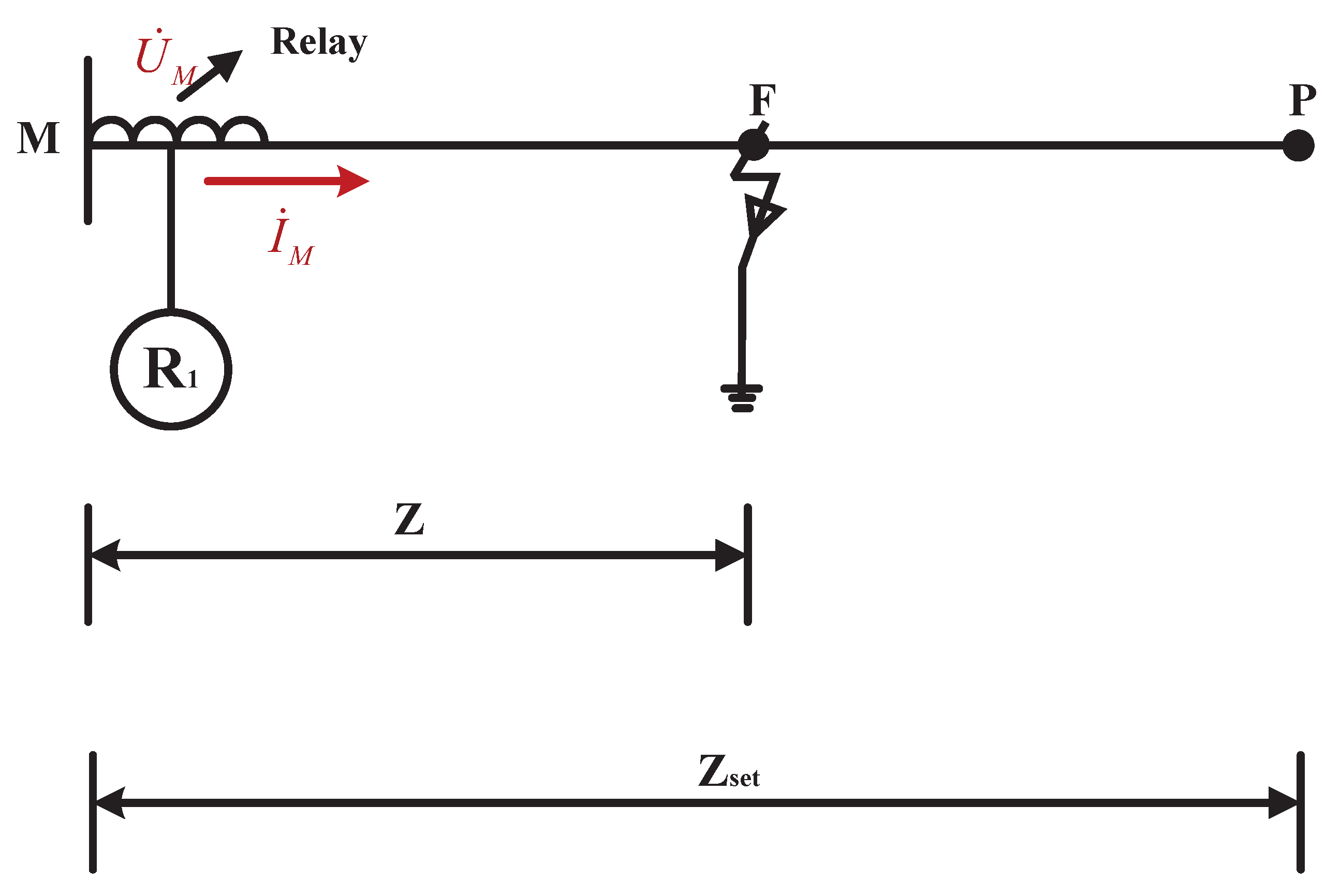
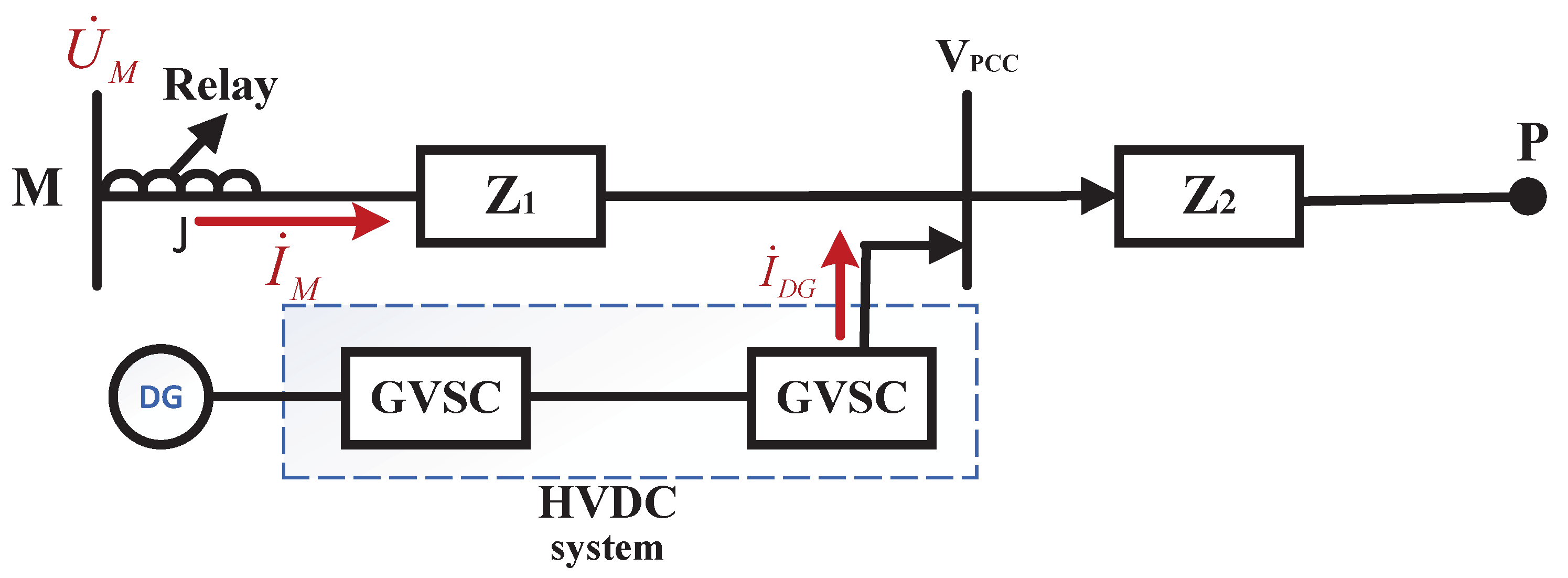
Traditional distance protection algorithms are based on short-circuit models that often neglect fault transition resistance. The short-circuit model of a transmission line without considering fault resistance is shown in Figure 1.
In this model, F denotes the fault point. The section MP defines the designated protection zone, where the line impedance of this zone is the set value Z set . If a fault occurs between M and P, the distance relay will operate. The relay will trip when the measured impedance Z at the relay location is smaller than Z set . For clarity, all voltages and currents with an overdot in this paper denote RMS phasor quantities. Accordingly, U ˙ M , U ˙ F , U ˙ P C C , I ˙ M , and I ˙ D G are complex phasors. The impedances Z, Z 1 , Z 2 , and Z set are complex quantities, which can generally be written as Z = R + j X . By contrast, R F denotes the fault transition resistance and is a real-valued quantity. The notation | · | represents the magnitude of a phasor or complex quantity, ( · ) denotes its phase angle, and Real ( · ) and Imag ( · ) denote its real and imaginary parts, respectively. Unless otherwise stated, no instantaneous quantities are used in the derivation. Under the assumption of zero transition resistance ( U F = 0 , where U F is the voltage at the fault point), the measured impedance Z is calculated as:
Z = U ˙ M I ˙ M
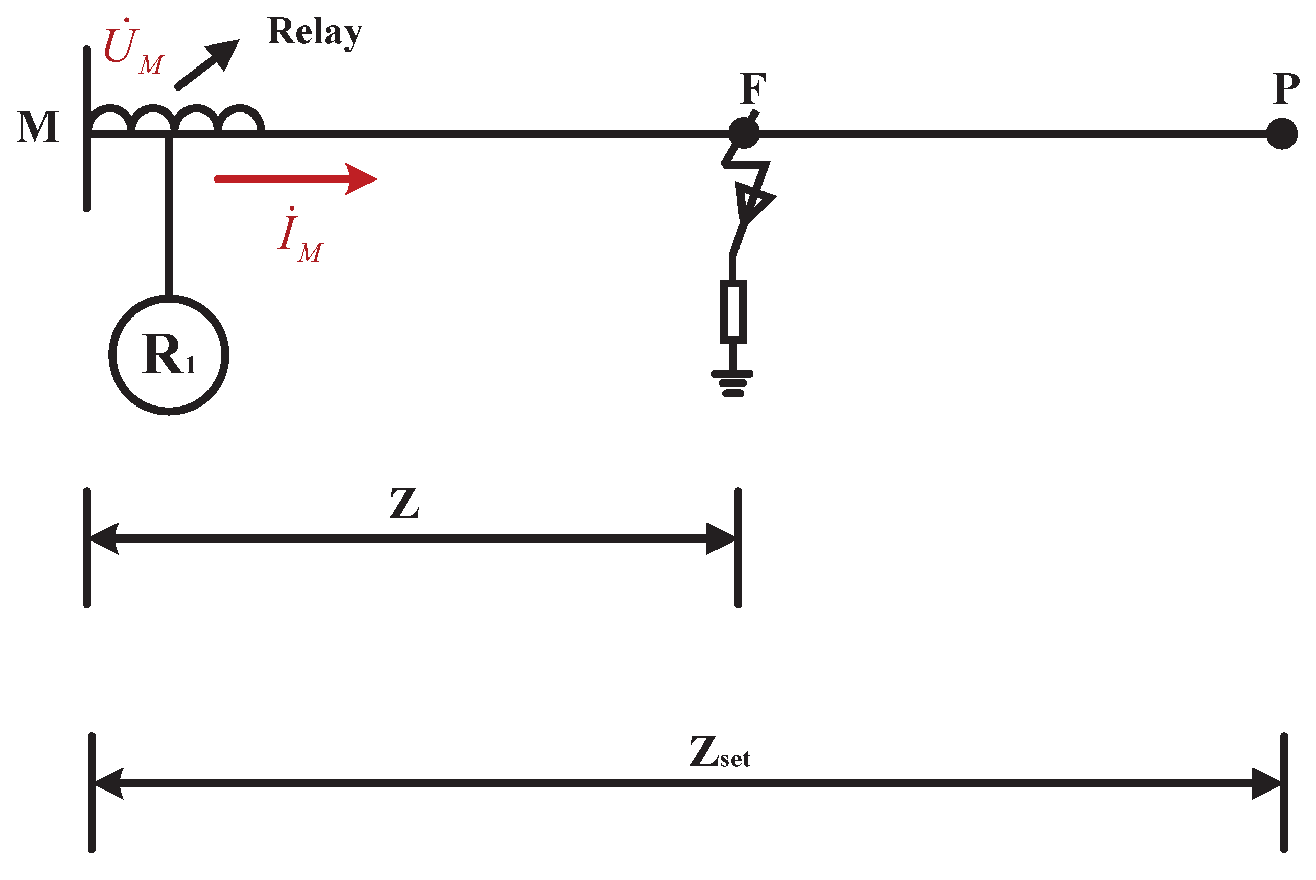
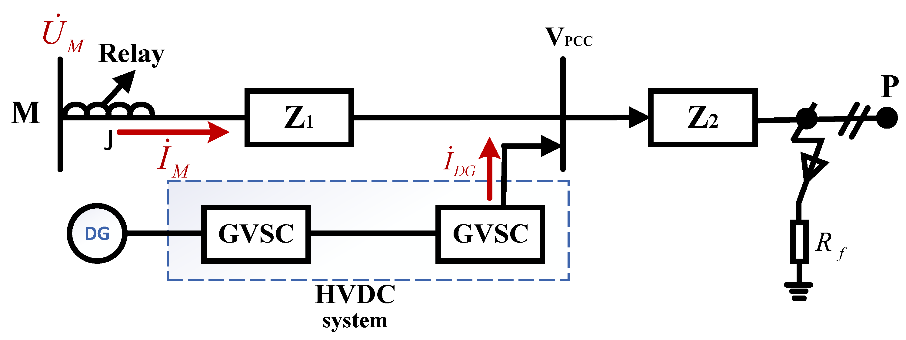
where U ˙ M and I ˙ M represent the measured voltage and current, respectively, at the measuring point M. However, when a transition resistance R F is present and U F 0 , as shown in Figure 2, the observed impedance becomes:
U ˙ M I ˙ M = I ˙ M Z + U ˙ F I ˙ M = I ˙ M Z + R F I ˙ M I ˙ M = Z + R F
Equation (2) clearly indicates that the measured impedance Z is increased by the transition resistance R F , which can lead to protection non-operation (underreach) when the fault occurs near the protection zone boundary.

2.2. The Impact of Distributed Generation Integration on Distance Protection Algorithms

The integration of distributed generation further complicates the impedance measurement. Figure 3 shows the high-voltage direct current (HVDC) transmission system with integrated distributed generation, where I ˙ DG represents the GVSC current. This DG current injection is an important factor that cannot be neglected in short-circuit fault impedance measurements. Figure 4 shows a short-circuit model of a high-voltage AC transmission system with distributed generation.
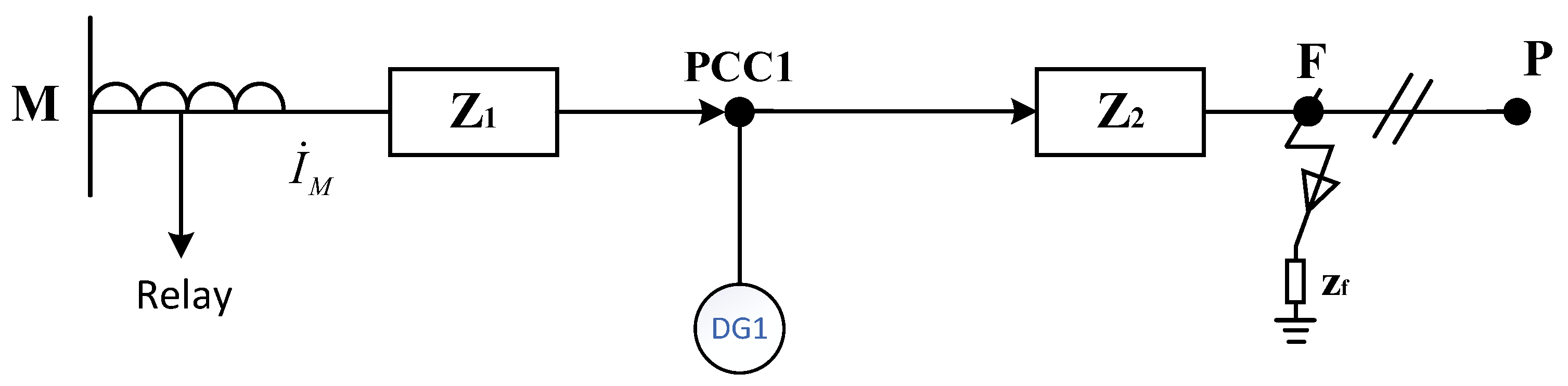
In this model, Z 1 is the impedance from the relay to the point of common coupling (PCC), and Z 2 is the impedance from the PCC to the fault point. The measured impedance at M is derived as follows:
U ˙ M I ˙ M = ( R F + Z 2 ) ( I ˙ M + I ˙ DG ) + Z 1 I ˙ M I ˙ M   = Z + R F + ( R F + Z 2 ) I ˙ DG I ˙ M
where Z = Z 1 + Z 2 . Equation (3) reveals an additional error term ( R F + Z 2 ) ( I ˙ DG / I ˙ M ) compared to (2), which cannot be ignored and complicates the accurate fault location.

3. Proposed Novel Distance Protection Scheme

3.1. Accurate Impedance Estimation Under Fault Transition Resistance

As shown in Figure 2, in the short-circuit model considering fault transition resistors, there are transition resistors. In this circuit, U ˙ M , U ˙ F , Z , R F and I ˙ M satisfy:
U ˙ M = I ˙ M Z + U ˙ F U ˙ F = I ˙ M R F
To achieve accurate distance protection, it is essential to obtain the precise value of Z. Based on the information above, knowing U ˙ M and U ˙ F , it is also specified that I ˙ M = | I ˙ M | 0 ° , and the following relationships can be established.
Real ( U ˙ M ) =   | I ˙ M | Real ( Z ) + | U ˙ F | Imag ( U ˙ M ) =   | I ˙ M | Imag ( Z ) U ˙ F =   | I ˙ M | R F
Thus, we obtain: Imag ( Z ) = Imag ( U ˙ M ) / | I ˙ M | . If the line’s R/X ratio is known, the impedance Z can be determined. This paper proposes a simplified method based on precise harmonic analysis to solve for Z.
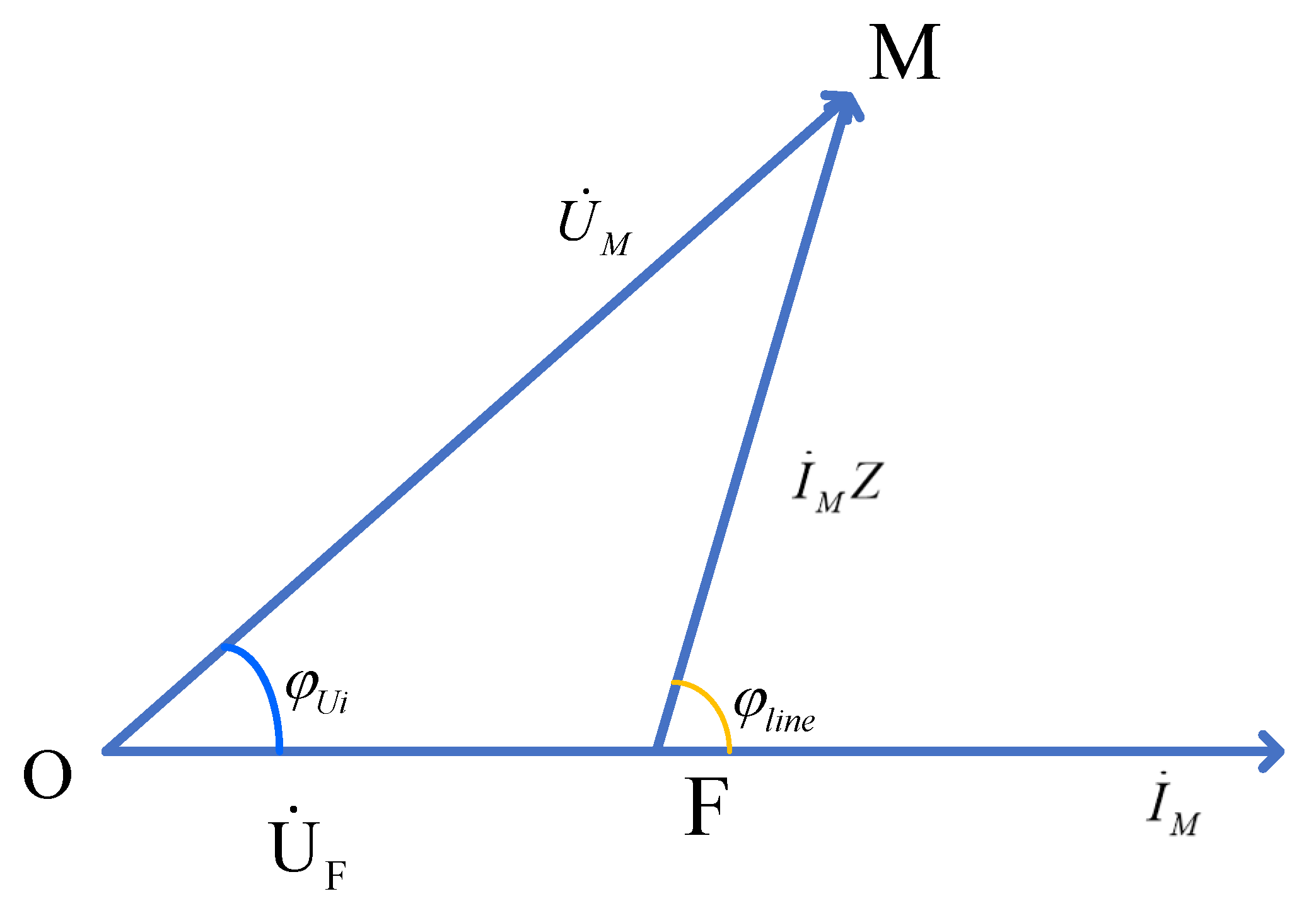
The phasor diagrams of U ˙ M , U ˙ F , and I ˙ M are shown in Figure 5. Here, φ line denotes the phase angle of the transmission line, and φ u i is the phase-angle difference between U ˙ M and I ˙ M .
Note that because the line R / X ratio is known, φ line is determined. U ˙ M , I ˙ M , and φ u i are the measured quantities of the relay protection device.
Applying the law of sines to triangle O F M yields:
| O M | sin ( π φ line ) = | M F | sin φ u i
According to Figure 5, it is known that | O M | = | U ˙ M | and | M F | = | I ˙ M | | Z | . Substituting these expressions into (6) yields:
| Z | = | U ˙ M | | I ˙ M | sin φ u i sin φ line
Therefore, the impedance Z can be expressed as:
Z = | U ˙ M | | I ˙ M | sin φ u i sin φ line ( cos φ line + j sin φ line )
Consequently, the fault criterion in a single-DG system can be expressed as follows: when | Z |   <   | Z set | , a short-circuit fault is identified and the corresponding protective action is triggered.

3.2. Distance Protection Algorithm Considering Distributed Generation Integration

As shown in Figure 4, let U ˙ PCC represent the voltage at the point of common coupling (PCC). The mathematical relationship among U ˙ M , U ˙ F , and U ˙ PCC can be formally defined by the following expressions:
U ˙ M = I ˙ M Z 1 + U ˙ PCC , U ˙ F = ( I ˙ D G + I ˙ M ) R F , U ˙ PCC = ( I ˙ D G + I ˙ M ) Z 2 + U ˙ F
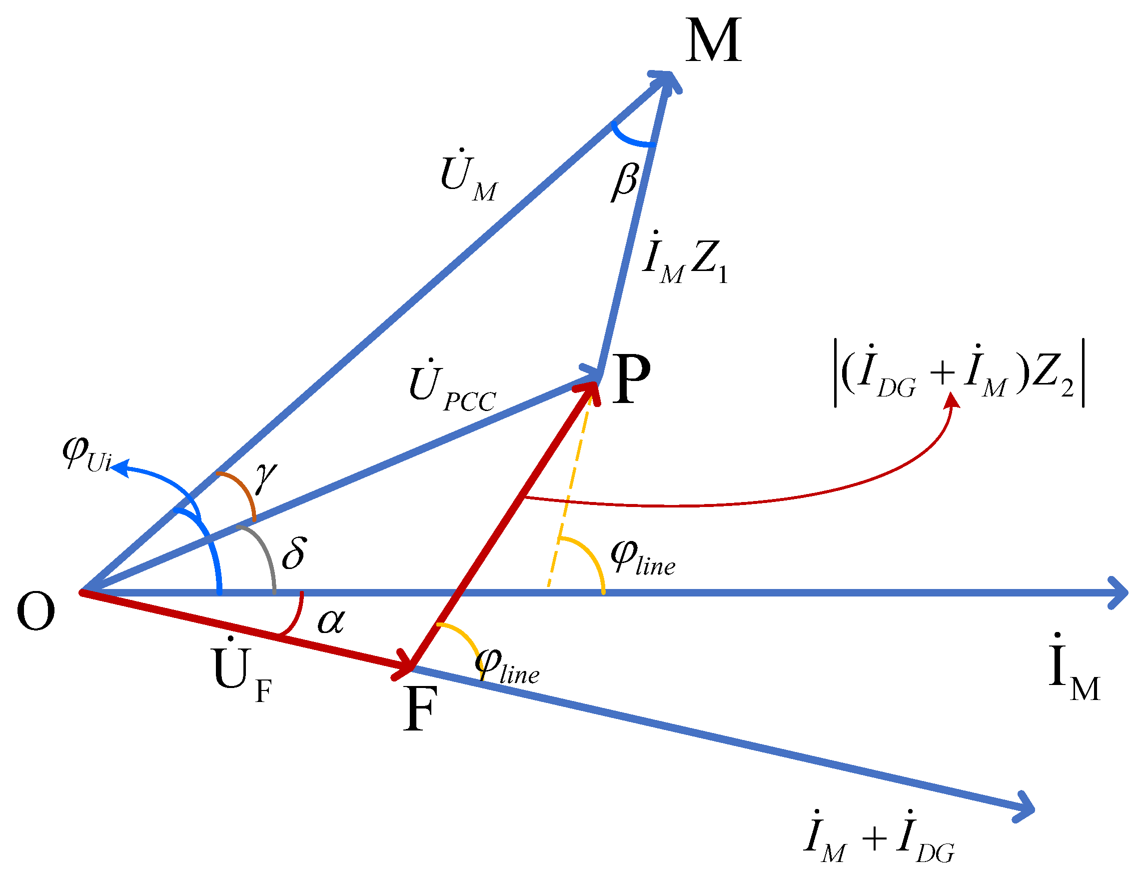
The phasor relationships among U ˙ M , U ˙ F , and U ˙ PCC are illustrated in Figure 6. Evidently, the voltage phasor relationship is more complex than that in Figure 5. Due to the presence of I ˙ D G , it is not possible to directly determine U ˙ M solely based on the locally measured current I ˙ M and the impedances Z 1 , Z 2 , and R F .
To realize the local measurement of the impedance between the relay and the fault point, the following assumptions are made:
  • The impedance Z 1 from the relay to the point of common coupling (PCC) is known;
  • The R / X ratios of Z 1 and Z 2 are identical under the homogeneous-line assumption adopted in this paper;
  • The PCC point is assumed to be unloaded, and all loads are connected to the system bus P.
In practice, the distance between the relay and the PCC point is fixed, and its impedance can be pre-measured. Assumption 2 follows from the homogeneous-line model adopted in this paper. If the relay, PCC, and fault point are located on the same transmission line type, the per-unit-length impedance can be written as z = r + j x . Then, for two line sections with lengths l 1 and l 2 , we have Z 1 = l 1 ( r + j x ) , Z 2 = l 2 ( r + j x ) . Therefore, R 1 X 1 = R 2 X 2 = r x , which means that Z 1 and Z 2 have the same impedance angle.
For clarity, the current phasor I ˙ M is taken as the angular reference, i.e., I ˙ M = 0 . The angle ϕ u i denotes the measured phase-angle difference between U ˙ M and I ˙ M . Since Z 1 and Z 2 are assumed to have the same R / X ratio, both line sections share the same impedance angle ϕ l i n e . Accordingly, the voltage drop I ˙ M Z 1 forms an angle ϕ l i n e with respect to I ˙ M .
Based on Figure 6, the auxiliary angles are defined step by step as follows. First, β is the included angle in triangle O M P between the phasors U ˙ M and I ˙ M Z 1 , and therefore β = π ( ϕ l i n e + ϕ u i ) . Second, γ is the angle between U ˙ M and U ˙ P C C , obtained from triangle O M P by the law of sines. Third, δ is the phase-angle difference between U ˙ P C C and the reference current I ˙ M , which can be written as δ = ϕ u i γ . Finally, α denotes the angle between the total current flowing through Z 2 , namely ( I ˙ M + I ˙ D G ) , and the reference current I ˙ M . Therefore, α + δ represents the phase-angle difference between U ˙ P C C and the total current through Z 2 . The available quantities are | U ˙ M | , | I ˙ M | , ϕ u i , ϕ l i n e , the known line impedance Z 1 , and the synchronized current magnitude | I ˙ D G + I ˙ M | .
According to Figure 6, | O M | = | U ˙ M | and | M P | = | I ˙ M Z 1 | . The included angle between U ˙ M and I ˙ M Z 1 is denoted by β , and from the phasor geometry it follows that
β = π ( ϕ l i n e + ϕ u i ) .
Therefore, in triangle O M P , application of the law of cosines yields the magnitude of the PCC voltage:
| U ˙ PCC |   = | U ˙ M | 2   +   | I ˙ M Z 1 | 2 + 2 | U ˙ M | | I ˙ M Z 1 | cos β
To establish the phase relationship at the PCC, the law of sines is applied to triangle O M P
| M P | sin γ = | U ˙ P C C | sin β
The angle γ is therefore determined as:
γ = arcsin | I ˙ M Z 1 | sin ( φ l i n e + φ u i ) | U ˙ P C C |
Consequently, the phase difference δ between the PCC voltage U ˙ P C C and the measured current I ˙ M is derived from the phasor geometry:
δ = φ u i γ
In triangle O P F , the voltage drop across the unknown impedance Z 2 is | F P | = | ( I ˙ M + I ˙ D G ) Z 2 | . Here, α denotes the angle between the total current phasor ( I ˙ M + I ˙ D G ) and the reference current I ˙ M . Therefore, the included angle at vertex P is α + δ . Reapplying the law of sines provides:
| ( I ˙ M + I ˙ D G ) Z 2 | sin ( α + δ ) = | U ˙ P C C | sin ( φ l i n e )
Solving for the magnitude of the faulted line impedance yields the core result of this analysis:
| Z 2 |   = | U ˙ P C C | sin ( α + δ ) | I ˙ M + I ˙ D G | sin ( φ l i n e )
The short-circuit criterion is defined as follows: when | Z 1 |   +   | Z 2 |   <   | Z set | , the fault is determined to be a short-circuit fault, and the corresponding protection action is triggered.
A significant practical simplification is attainable under specific measurement conditions. If synchronized measurements at the PCC provide the load-side current I ˙ l o a d = I ˙ M + I ˙ D G and its phase difference φ u i with respect to U ˙ P C C , then the relationship α + δ = φ u i holds. Substituting into (16) yields a simplified calculation:
| Z 2 | = sin ( φ u i ) | U ˙ PCC | sin ( φ line ) | I ˙ load |
It should be noted that the relay does not require the individual DG current I ˙ D G . Instead, it only requires the total current flowing through Z 2 , i.e., I ˙ l o a d = I ˙ M + I ˙ D G , whose magnitude and phase difference with respect to U ˙ P C C can be obtained directly from synchronized measurements at the PCC and transmitted to the relay through the communication link. In practice, synchronized measurements at the PCC and the relay can be implemented by equipping both locations with a common time reference, so that the sampled voltage and current phasors are time-aligned and can be used directly for the impedance calculation.
This formulation is formally analogous to the standard impedance calculation for radial systems without DG (c.f. (8)). This demonstrates that with appropriate synchronized measurements, the adverse effects of DG integration can be effectively neutralized, restoring the reliability of the distance protection principle.
Therefore, as long as the voltage amplitude at the PCC can be measured, the problem can be equivalently transformed into the case where no distributed power source is connected. Consequently, regardless of how many distributed generation systems are integrated or where they are connected, the impedance-based fault identification criterion remains valid.
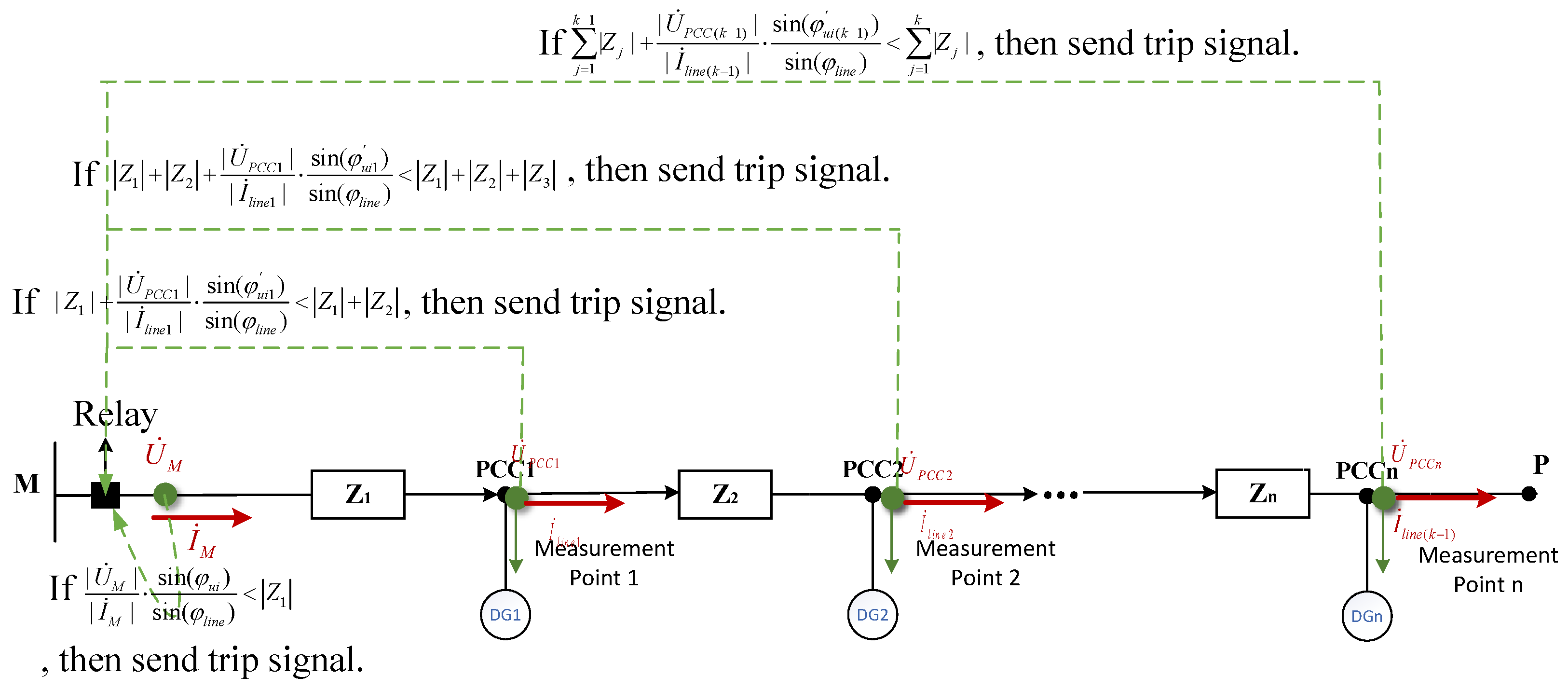
As shown in Figure 7, if there are n Points of Common Coupling (PCC) access points ( P C C 1 , P C C 2 , , P C C n ), the transmission line is divided into n + 1 segments. The intrinsic impedance of the k-th segment is denoted as Z k . A synchronization measurement unit is installed at the downstream side of every distributed power source access point. This device collects and measures the voltage magnitude, current magnitude, and their phase angles at the node in real-time. The system communicates through a dedicated communication link to transmit the distributed measurement data back to the primary protection device. The generalized formula for the equivalent impedance Z for a measurement node is as follows:
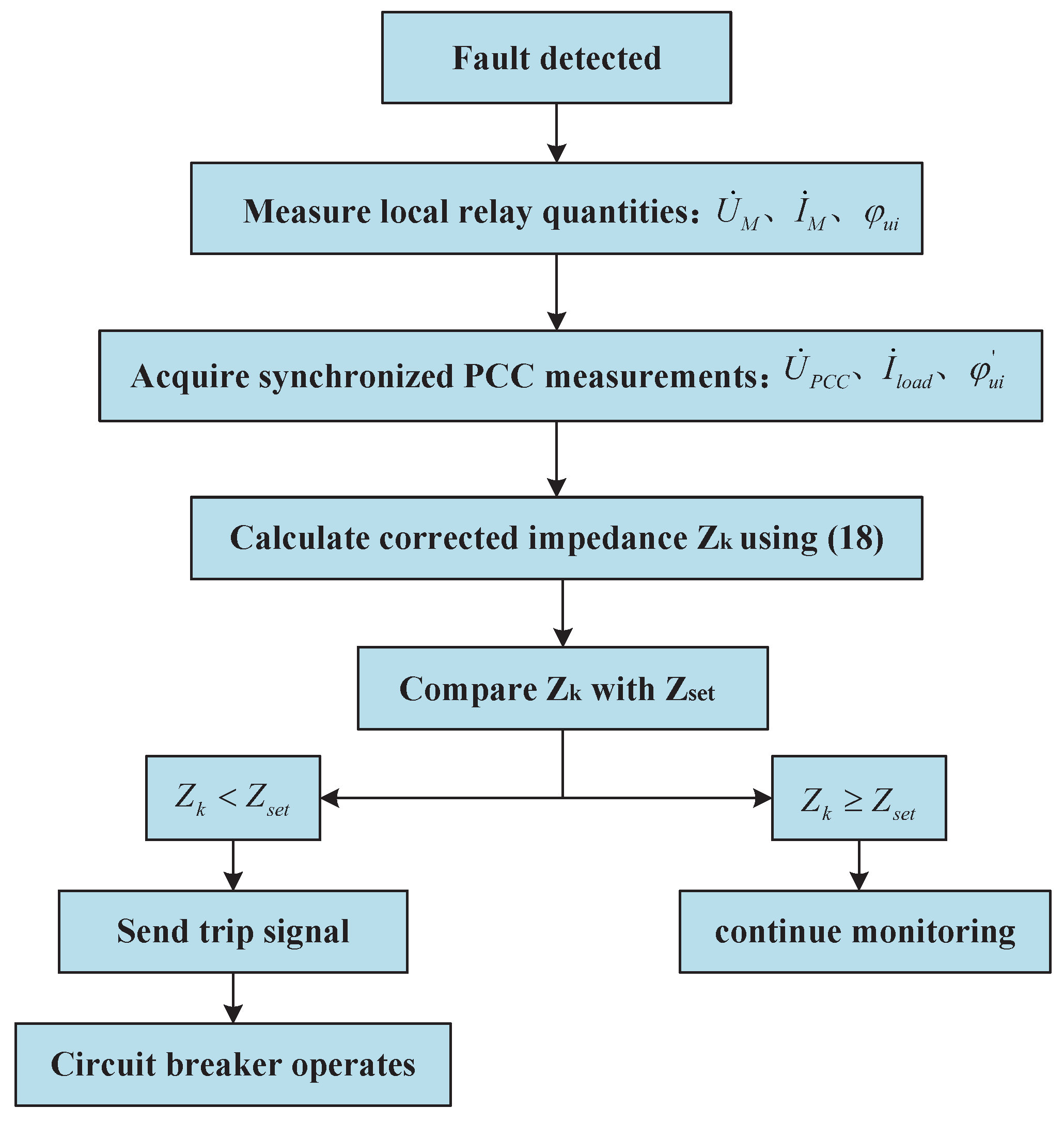
The logic of the distance protection scheme proposed in this paper is as follows: When a system fault occurs, the corrected impedance Z k calculated from the synchronized measurement data is compared to a pre-set fixed impedance Z set . If Z k < Z set , it is determined that the fault occurred within the current line protection zone. At this point, the measurement unit transmits a trip signal to the terminal circuit breaker through the communication channel, driving the breaker to operate and clear the fault.
Z k = U ˙ M I ˙ M · sin ( φ u i ) sin ( φ l i n e ) , k = 1 Z 1 + U ˙ P C C 1 I ˙ l i n e 1 · sin ( φ u i 1 ) sin ( φ l i n e ) , k = 2 j = 1 k 1 Z j + U ˙ P C C ( k 1 ) I ˙ l i n e ( k 1 ) · sin ( φ u i ( k 1 ) ) sin ( φ l i n e ) , k = 3 , , n + 1
where R s e t is the resistance setting value, and X s e t is the reactance setting value. If the measured impedance falls within the quadrilateral region, the relay will operate to provide protection. The operating criterion for the relay is as follows.
Where | Z j | is the known intrinsic impedance magnitude of the j-th segment. | U ˙ PCC ( k 1 ) | is the synchronized measured voltage magnitude at the ( k 1 ) -th PCC. | I ˙ line ( k 1 ) | is the measured current magnitude difference (i.e., the current flowing into the k-th segment) after the first k 1 PCC nodes. ϕ til ( k 1 ) is the phase angle between the voltage and the injected/out flowing current measured at the ( k 1 ) -th PCC node. ϕ line is the phase angle of the transmission line impedance.
The overall implementation procedure of the proposed distance protection scheme is summarized in Figure 8, including synchronized measurement acquisition, impedance calculation, protection decision, and breaker operation.

4. Simulations

To validate and evaluate the distance protection scheme proposed herein, two operational scenarios were constructed within MATLAB 2016b simulations: a single distributed power source system and a dual distributed power source system. A series of faults with varying transition resistances were simulated on the transmission lines to verify whether the proposed distance protection algorithm enables the distance protection relays to operate correctly.
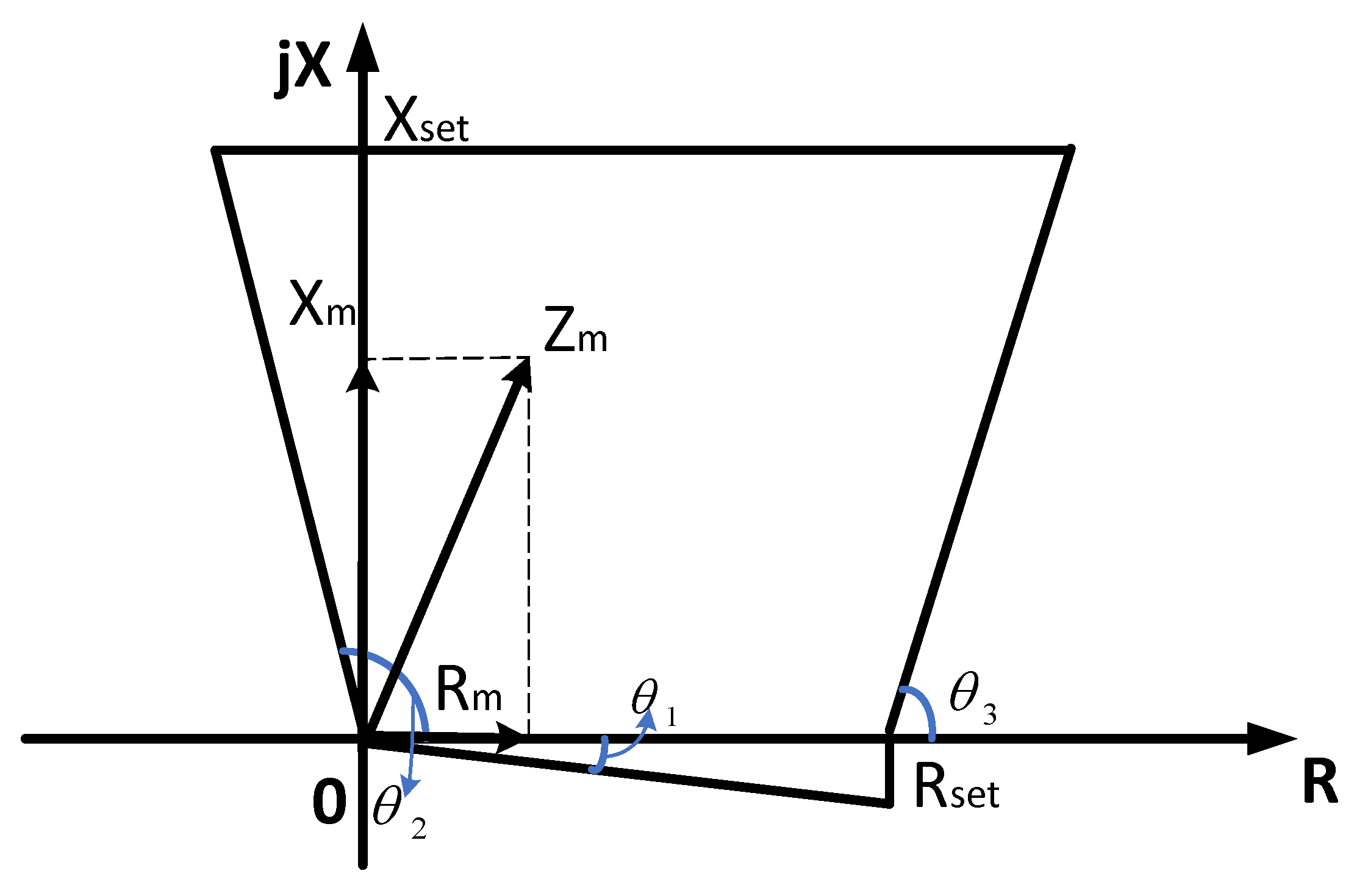
The core of protective decision-making in the simulations is the impedance relay, which has a directional quadrilateral operating characteristic. This characteristic is commonly used in distance protection to discriminate between forward and reverse faults; therefore, the operating zone may extend into the second quadrant (negative R) to provide reliable blocking for reverse faults. Its operating region, defined as a quadrilateral area, serves as the fixed boundary for fault identification. The four sides of this quadrilateral represent different fault conditions, and the operation of the relay is related to these boundary conditions, as shown in Figure 9, where R s e t is the resistance setting value, and X s e t is the reactance setting value. In Figure 9, the angles θ 1 , θ 2 , and θ 3 are independent parameters that define the shape of the quadrilateral: θ 1 is the angle between the lower-left boundary and the R-axis, θ 2 is the angle between the lower-left boundary and the X-axis, and θ 3 is the angle between the right-hand boundary and the horizontal line. These three angles are set independently according to the protection requirements. If the measured impedance falls within the quadrilateral region, the relay will operate to provide protection. The operating criterion for the relay is as follows.
R m tan θ 1 X m X s e t , X m cot θ 2 R m R s e t + X m cot θ 3 .
In the formula, θ 1 , θ 2 , and θ 3 , are the predefined parameters; X m , R m are the measured resistance and reactance in the impedance relay.

4.1. Single Distributed Generation System

Simulations were conducted on the single distributed generation system depicted in Figure 10. A 300 kV AC transmission system was established, with the DG connected to PCC1 via a grid-connected voltage-source converter (GVSC). All line sections employed identical cable types with consistent R / X ratios, thereby satisfying Assumption 2, and the line impedance angle was set to ϕ line = 67.3 ° . The equivalent impedance from the relay to PCC1 is Z 1 = 7.6 + j 18.2   Ω , while the equivalent impedance from the fault point to PCC1 is Z 2 = 13.3 + j 31.85   Ω . The system’s input quantities comprise solely the voltage magnitude at PCC1, the magnitude of the primary-side current after grid connection, and the phase angle between these two quantities. Accordingly, for the quadrilateral relay shown in Figure 9, the settings are chosen as R set = 20.9 Ω and X set = 50.05 Ω , which correspond to the total line resistance and reactance from the relay location to the fault point.
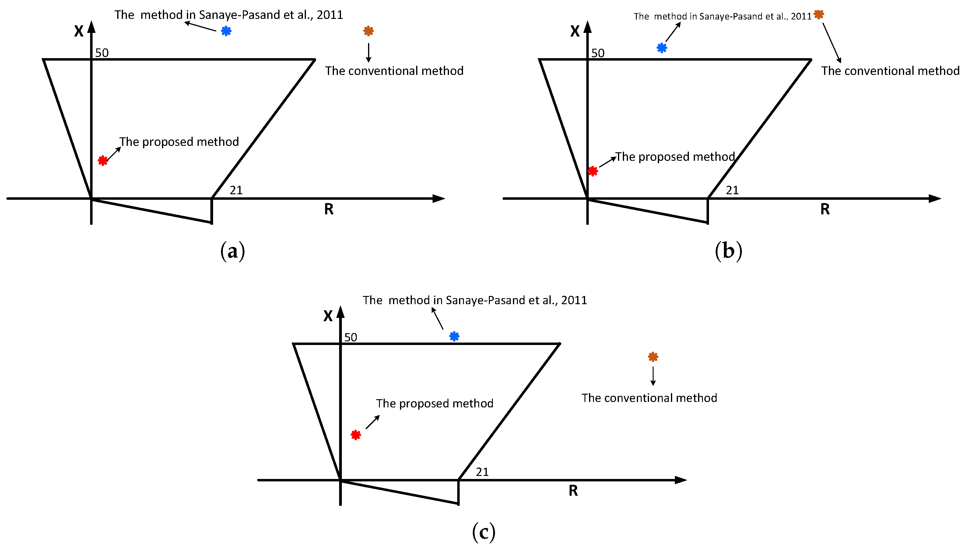
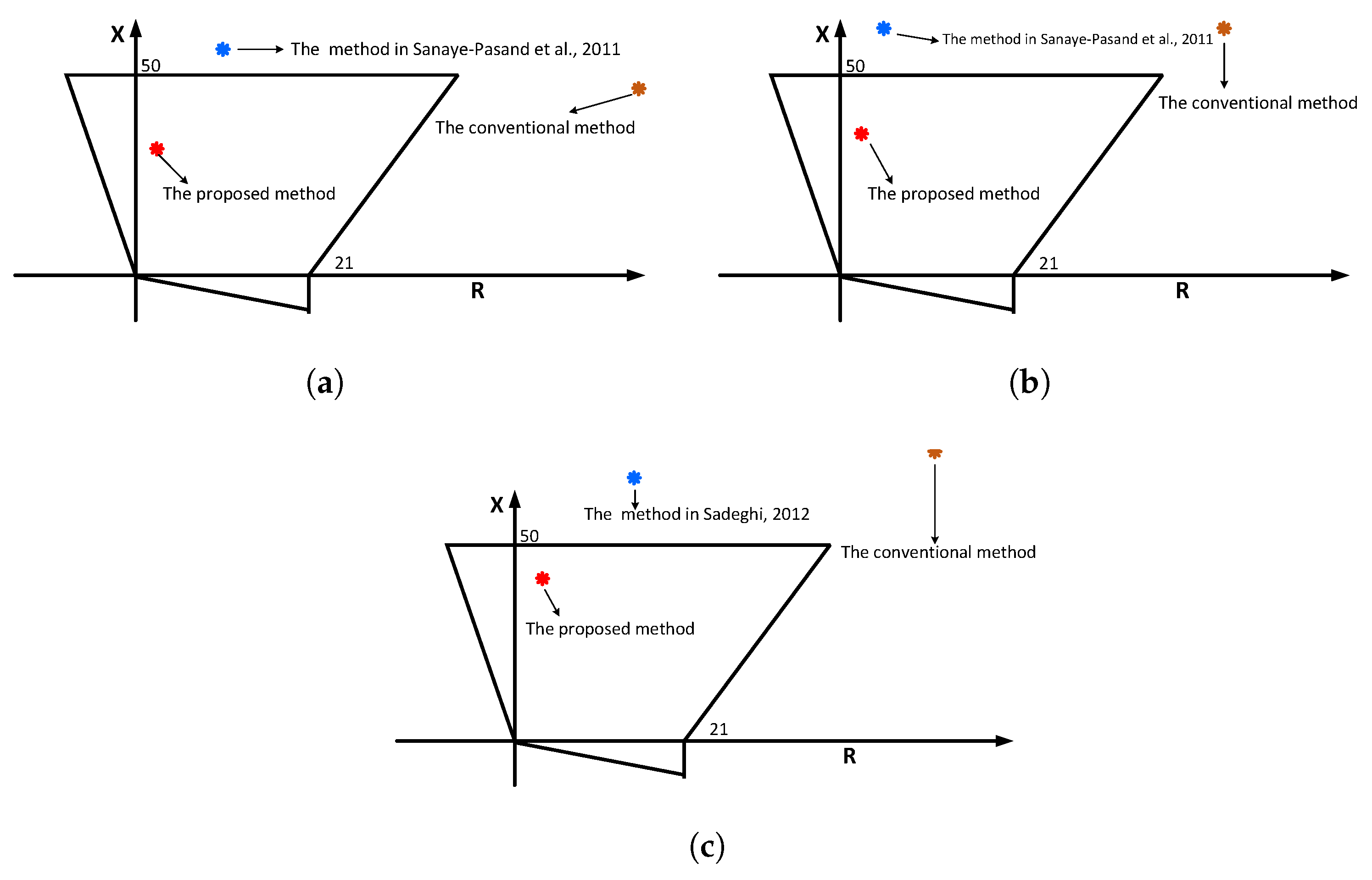
When a single-phase ground fault occurs at point F, the results of three distance protection schemes are compared: the conventional scheme Z = U ˙ M / I ˙ M , the method in [16] that controls the GVSC to achieve I ˙ D G = α I ˙ M , and the scheme proposed herein. The comparison is shown in Figure 11 below. Three transition resistances are tested: 50 Ω , 100 Ω , and 150 Ω . These values are selected to represent low, medium, and relatively high transition-resistance conditions, so that the effectiveness and robustness of the proposed scheme can be examined under increasingly severe fault-resistance effects. In the figure, the quadrilateral represents the relay setting boundary; the red asterisk denotes the measured value obtained by the proposed extreme-protection algorithm, the yellow asterisk indicates the measured value from the conventional distance protection algorithm, and the blue asterisk shows the result of the method in [16]. Figure 11 demonstrates that the conventional distance protection scheme exhibits significant errors due to the superposition of DG backflow and transition impedance. In the tested cases of this paper, the reproduced benchmark from [16] exhibits an impedance-estimation error of about 10%. In contrast, the scheme proposed herein achieves adaptive protection measurements that consistently fall within the relay operating zone under various transition resistances, thereby enabling the relay to operate correctly.

4.2. Dual Distributed Generation System

A system incorporating dual distributed generation (DG) sources was constructed, as shown in Figure 12. Similarly, no control was applied to the converter side in this system. The magnitude and phase angle of the DG injection current varied spontaneously with operating conditions, and the relationship I ˙ D G = α I ˙ M no longer held.
As with the single distributed generation system, the input quantities for this system are solely the voltage magnitude at PCC2 and the phasor of the primary-side current following grid connection (magnitude and phase angle). The transition impedance and other line parameters remain consistent with those described previously. To preserve the same total relay-to-fault line impedance as that in the single-DG case, the line section from PCC1 to the fault point is divided into two homogeneous subsections, and thus the quadrilateral relay settings remain R set = 20.9 Ω and X set = 50.05 Ω . When I ˙ D G = α I ˙ M cannot be enforced, α can only be passively estimated, and its error increases significantly with phase-angle drift and the grid connection ratio. As shown in Figure 13, under dual-source conditions, substantial deviations occur. The distance protection algorithm proposed herein ensures that all protected measurements remain within the operating zone in dual distributed generation systems, thereby enabling the distance protection to function correctly.

5. Conclusions

This paper proposes a novel distance protection method that effectively compensates for impedance measurement errors caused by fault transition resistance and the integration of distributed generation. By constructing an improved fault model and incorporating voltage and current phasor diagrams, the method achieves accurate estimation of fault impedance. The study demonstrates that, under known R / X ratios and measured voltage and current at the point of common coupling (PCC), the system with distributed generation can be equivalently transformed into a traditional unidirectional power flow system. This transformation simplifies the protection criteria and enhances the sensitivity and selectivity of the protection scheme. Moreover, the proposed method is applicable to resistive, capacitive, and inductive transition impedance scenarios, exhibiting strong generality and robustness.
Nevertheless, some limitations of the present work should be noted. The proposed derivation is established under the homogeneous-line assumption, i.e., the relevant line sections are assumed to share the same impedance angle. In addition, the method relies on synchronized measurements and communication support at the PCC, and the impacts of practical non-ideal factors such as measurement noise, synchronization error, and communication delay have not been fully investigated in this paper. Future work will therefore focus on extending the proposed method to heterogeneous line configurations, evaluating its robustness under non-ideal measurement and communication conditions, and validating its performance through real-time simulation or hardware-in-the-loop experiments.

Author Contributions

Conceptualization, K.C. and Z.L.; Methodology, B.L., Z.L. and Y.S. All authors have read and agreed to the published version of the manuscript.

Funding

This research received no external funding.

Data Availability Statement

The original contributions presented in this study are included in the article. Further inquiries can be directed to the corresponding author.

Conflicts of Interest

Authors Kai Chen and Binbin Liu were employed by the company China Railway Siyuan Survey and Design Co., Ltd. The remaining authors declare that the research was conducted in the absence of any commercial or financial relationships that could be construed as a potential conflict of interest.

References

  1. Li, Z.; Lin, X.; Weng, H.; Bo, Z. Efforts on improving the performance of superimposed-based distance protection. IEEE Trans. Power Deliv. 2011, 27, 186–194. [Google Scholar] [CrossRef]
  2. Ji, L.; Shi, J.; Hong, Q.; Fu, Y.; Chang, X.; Cao, Z.; Mi, Y.; Li, Z.; Booth, C. A multi-objective control strategy for three phase grid-connected inverter during unbalanced voltage sag. IEEE Trans. Power Deliv. 2020, 36, 2490–2500. [Google Scholar] [CrossRef]
  3. Zhang, F.; Mu, L. A fault detection method of microgrids with grid-connected inverter interfaced distributed generators based on the PQ control strategy. IEEE Trans. Smart Grid 2018, 10, 4816–4826. [Google Scholar] [CrossRef]
  4. Andreev, M.; Suvorov, A.; Askarov, A.; Kievets, A.; Rudnik, V. Impact of renewables on relay protection operation. Prz. Elektrotechniczny 2019, 95, 42–47. [Google Scholar] [CrossRef]
  5. Horowitz, S.H.; Phadke, A.G.; Henville, C.F. Power System Relaying; John Wiley & Sons: Hoboken, NJ, USA, 2022. [Google Scholar]
  6. Eissa, M. Ground distance relay compensation based on fault resistance calculation. IEEE Trans. Power Deliv. 2006, 21, 1830–1835. [Google Scholar] [CrossRef]
  7. Liu, Q.; Huang, S.; Liu, H.; Liu, W. Adaptive impedance relay with composite polarizing voltage against fault resistance. IEEE Trans. Power Deliv. 2008, 23, 586–592. [Google Scholar] [CrossRef]
  8. Makwana, V.H.; Bhalja, B.R. A new digital distance relaying scheme for compensation of high-resistance faults on transmission line. IEEE Trans. Power Deliv. 2012, 27, 2133–2140. [Google Scholar] [CrossRef]
  9. Toader, D.; Vintan, M. Mathematical Models of the Phase Voltages of High-, Medium-and Low-Voltage Busbars in a Substation during a Phase-to-Ground Fault on High-Voltage Busbars. Mathematics 2023, 11, 3032. [Google Scholar] [CrossRef]
  10. Liang, Y.; Li, W.; Lu, Z.; Xu, G.; Wang, C. A new distance protection scheme based on improved virtual measured voltage. IEEE Trans. Power Deliv. 2019, 35, 774–786. [Google Scholar] [CrossRef]
  11. Ma, J.; Ma, W.; Qiu, Y.; Thorp, J.S. An adaptive distance protection scheme based on the voltage drop equation. IEEE Trans. Power Deliv. 2015, 30, 1931–1940. [Google Scholar] [CrossRef]
  12. Song, G.; Chu, X.; Gao, S.; Kang, X.; Jiao, Z.; Suonan, J. Novel distance protection based on distributed parameter model for long-distance transmission lines. IEEE Trans. Power Deliv. 2013, 28, 2116–2123. [Google Scholar] [CrossRef]
  13. Xu, Z.Y.; Xu, G.; Ran, L.; Yu, S.; Yang, Q. A new fault-impedance algorithm for distance relaying on a transmission line. IEEE Trans. Power Deliv. 2010, 25, 1384–1392. [Google Scholar] [CrossRef]
  14. Araújo, M.R.; Pereira, C. Distance protection algorithm for long parallel transmission lines with no common bus. IEEE Trans. Power Deliv. 2019, 35, 1059–1061. [Google Scholar] [CrossRef]
  15. Sadeghi, H. A novel method for adaptive distance protection of transmission line connected to wind farms. Int. J. Electr. Power Energy Syst. 2012, 43, 1376–1382. [Google Scholar] [CrossRef]
  16. Sanaye-Pasand, M.; Jafarian, P. An adaptive decision logic to enhance distance protection of transmission lines. IEEE Trans. Power Deliv. 2011, 26, 2134–2144. [Google Scholar] [CrossRef]
  17. Hu, Y.; Novosel, D.; Saha, M.M.; Leitloff, V. An adaptive scheme for parallel-line distance protection. IEEE Trans. Power Deliv. 2002, 17, 105–110. [Google Scholar] [CrossRef]
  18. Makwana, V.H.; Bhalja, B.R. A new adaptive distance relaying scheme for mutually coupled series-compensated parallel transmission lines during intercircuit faults. IEEE Trans. Power Deliv. 2011, 26, 2726–2734. [Google Scholar] [CrossRef]
  19. Singh, A.R.; Dambhare, S.S. Adaptive distance protection of transmission line in presence of SVC. Int. J. Electr. Power Energy Syst. 2013, 53, 78–84. [Google Scholar] [CrossRef]
  20. Biswal, M.; Pati, B.B.; Pradhan, A.K. Adaptive distance relay setting for series compensated line. Int. J. Electr. Power Energy Syst. 2013, 52, 198–206. [Google Scholar] [CrossRef]
  21. Liu, Z.; Liu, R.; Zhang, X.; Su, M.; Sun, Y.; Han, H.; Wang, P. Feasible power-flow solution analysis of DC microgrids under droop control. IEEE Trans. Smart Grid 2020, 11, 2771–2781. [Google Scholar] [CrossRef]
  22. Liu, Z.; Su, M.; Sun, Y.; Zhang, X.; Liang, X.; Zheng, M. A comprehensive study on the existence and stability of equilibria of DC-distribution networks with constant power loads. IEEE Trans. Autom. Control 2021, 67, 1988–1995. [Google Scholar] [CrossRef]
  23. Chen, X.; Shi, M.; Sun, H.; Li, Y.; He, H. Distributed cooperative control and stability analysis of multiple DC electric springs in a DC microgrid. IEEE Trans. Ind. Electron. 2017, 65, 5611–5622. [Google Scholar] [CrossRef]
  24. Sidhu, T.S.; Varma, R.K.; Gangadharan, P.K.; Albasri, F.A.; Ortiz, G.R. Performance of distance relays on shunt-FACTS compensated transmission lines. IEEE Trans. Power Deliv. 2005, 20, 1837–1845. [Google Scholar] [CrossRef]
  25. Albasri, F.A.; Sidhu, T.S.; Varma, R.K. Performance comparison of distance protection schemes for shunt-FACTS compensated transmission lines. IEEE Trans. Power Deliv. 2007, 22, 2116–2125. [Google Scholar] [CrossRef]
  26. Dash, P.; Pradhan, A.; Panda, G.; Liew, A. Adaptive relay setting for flexible AC transmission systems (FACTS). IEEE Trans. Power Deliv. 2002, 15, 38–43. [Google Scholar] [CrossRef]
Figure 1. Short-circuit model of transmission lines without considering short-circuit resistance.
Electronics 15 01431 g001
Figure 2. Short-circuit model of transmission lines considering short-circuit resistance.
Electronics 15 01431 g002
Figure 3. HVDC transmission system with integrated distributed generation.
Electronics 15 01431 g003
Figure 4. Short-circuit model of a high-voltage AC transmission system with distributed generation.
Electronics 15 01431 g004
Figure 5. Vector diagram of voltages U M , U F , and current I M .
Electronics 15 01431 g005
Figure 6. Voltage and current phasor diagram.
Electronics 15 01431 g006
Figure 7. Topology of optimized distance protection for multiple DG connections.
Electronics 15 01431 g007
Figure 8. Flowchart of the proposed distance protection scheme.
Electronics 15 01431 g008
Figure 9. The operating characteristics of quadrilateral characteristic impedance components.
Electronics 15 01431 g009
Figure 10. Single distributed power supply system architecture diagram.
Electronics 15 01431 g010
Figure 11. Comparison of three distance protection schemes under varying transition resistance (single-DG system). (a) 50 Ω . (b) 100 Ω . (c) 150 Ω [15,16].
Electronics 15 01431 g011
Figure 12. Dual distributed power supply system architecture diagram.
Electronics 15 01431 g012
Figure 13. Comparison of three distance protection schemes under varying transition resistance (Dual-DG system). (a) 50 Ω . (b) 100 Ω . (c) 150 Ω [16].
Electronics 15 01431 g013
Disclaimer/Publisher’s Note: The statements, opinions and data contained in all publications are solely those of the individual author(s) and contributor(s) and not of MDPI and/or the editor(s). MDPI and/or the editor(s) disclaim responsibility for any injury to people or property resulting from any ideas, methods, instructions or products referred to in the content.