Article

Research on Resource Optimization Algorithm for IRS-Assisted Multi-Hop Relay Networks in Power Wireless Private Networks

School of Electrical and Electronic Engineering, North China Electric Power University, Beijing 100096, China
*
Author to whom correspondence should be addressed.
Electronics 2026, 15(13), 2836; https://doi.org/10.3390/electronics15132836
Submission received: 26 May 2026 / Revised: 18 June 2026 / Accepted: 24 June 2026 / Published: 29 June 2026

Abstract

To address the energy efficiency optimization problem in power wireless private networks caused by fixed node positions, strong coupling between relay selection and power allocation, and strict quality of service (QoS) constraints, an intelligent reflecting surface (IRS)-assisted hybrid multi-hop relay network model is proposed. An IRS is deployed on the surface of an obstacle located between the source node and the first-hop relay to specifically enhance the first-hop link. By integrating path planning and cooperative power control, a joint optimization problem is formulated to maximize the system energy efficiency. To tackle the coupling issues in resource allocation, a joint optimization algorithm based on the block coordinate descent framework is developed, where the original problem is decomposed into three subproblems: relay selection, power allocation, and IRS phase shift configuration. These subproblems are solved using a greedy strategy, the Dinkelbach method, and a closed-form phase alignment solution, respectively. Simulation results demonstrate that the proposed algorithm outperforms conventional schemes in terms of system energy efficiency, reliability, and latency, making it suitable for power communication scenarios with extremely stringent QoS requirements.

1. Introduction

As the “nervous system” of the smart grid, the power wireless private network carries critical services such as relay protection and load control, which impose extremely high requirements on communication reliability (outage probability below 10 5 ) and latency (on the order of milliseconds) [1,2]. However, China’s power grid covers a vast geographical area, and within substations, distribution stations, and other sites, obstacles such as transformers, buildings, and equipment cabinets are densely distributed, leading to numerous blind spots and shadow fading regions for wireless signals. This severely restricts the coverage capability and transmission reliability of power wireless private networks [3,4].
Multi-hop relay technology, which deploys relay nodes between source and destination for store-and-forward transmission, can effectively bypass obstacles and extend network coverage, making it an important means to address communication blind spots in complex power station environments. Its successful application in a 220 kV substation by the Jiangsu Electric Power Research Institute has verified its engineering feasibility in multi-obstacle scenarios [5]. However, in power scenarios with fixed node positions and rigid topology, traditional multi-hop relay networks are often forced to increase transmit power to meet strict quality-of-service (QoS) constraints, leading to a drastic increase in energy consumption and conflicting with green and low-carbon goals. During the extreme rainstorm disaster in Zhengzhou in 2021, a large number of base stations failed and optical cables were damaged, causing some substations to lose contact with the dispatch center and resulting in prolonged paralysis of the distribution automation system [6]. Therefore, breaking through the existing resource optimization paradigm and investigating novel high-energy-efficiency resource co-optimization mechanisms under extreme QoS constraints has become a core research topic for the development of power wireless private networks.
Substantial research achievements have been made in resource optimization for multi-hop relay networks. Early works mostly focused on a single dimension, such as relay selection or power control. For two-hop scenarios, references [7,8,9] discussed relay selection strategies based on location and channel information, maximum received signal-to-noise ratio, and an improved A* algorithm, respectively; references [10,11,12,13] concentrated on power control, leveraging the Dinkelbach method, adaptive mechanisms, and joint energy-efficiency-delay optimization to improve energy efficiency. The above studies revealed the strong coupling between relay selection and power allocation and their joint decisive effect on network performance. However, existing studies are mostly confined to two-hop networks, and when facing the rigid topology and deterministic QoS constraints of power private networks in multi-hop scenarios, current algorithms show deficiencies in adaptability and global optimization capability [14,15]. Another common limitation of the above studies is that they are all built upon traditional active relays. The inherent energy consumption, noise introduction, and processing delay of active relays during signal processing place them in an inherent “performance vs. energy efficiency” trade-off dilemma when supporting ultra-reliable and low-latency communication (URLLC) services for the power grid.
In recent years, the intelligent reflecting surface (IRS) has emerged as a promising technology to overcome the above challenges. An IRS is composed of numerous programmable, low-power passive reflecting elements. By flexibly manipulating the phase of electromagnetic waves, it can actively reconfigure the wireless propagation environment, which not only expands signal coverage and improves link reliability but also features low cost and low energy consumption. Its seminal work was completed by Di Renzo et al., systematically elaborating the vision of “smart radio environments” [16]. Domestic reference [17] also provides a systematic review of IRS progress. At the core algorithm level, IRS phase shift optimization needs to handle the unit-modulus non-convex constraint, and manifold optimization has been proven to be a high-precision tool for dealing with this non-convex constraint, achieving successful application in beamforming design for multiple-input–multiple-output (MIMO) systems [18,19]. However, manifold optimization methods typically require complex steps such as computing Riemannian gradients, vector transport, and line search, needing iterative solutions and making it difficult to obtain closed-form solutions. Meanwhile, alternating optimization or block coordinate descent (BCD) frameworks have become mainstream paradigms for solving joint optimization of IRS and transmitter parameters [20,21]. In terms of IRS and relay cooperation, some scholars have studied resource allocation problems for IRS-assisted wireless powered communication network relay systems [22].
Despite the enormous potential of IRS technology, significant gaps still exist in its research for power multi-hop relay scenarios. First, existing IRS studies are mostly based on assumptions of civilian cellular networks, neglecting the rigid topology, fixed nodes, and strong deterministic QoS characteristics of power private networks, and rarely consider the fundamental constraints that extreme URLLC indicators impose on resource allocation [23]. Second, under the extreme constraints of power communication, the tightly coupled joint optimization of discrete relay selection, continuous power allocation, and non-convex IRS phase shifts is a complex problem that has not been fully explored. Reference [24] investigates IRS-assisted seamless connectivity in multi-hop networks but focuses on connectivity rather than energy efficiency, and does not consider strict URLLC constraints or joint optimization of relay selection and power allocation. Reference [25] addresses relay selection and power allocation for D2D communications without IRS assistance, and thus cannot exploit passive beamforming gains. References [26,27] incorporate IRS into wireless powered networks and general energy efficiency optimization, respectively, but are limited to two-hop or single-hop scenarios and rely on iterative algorithms without closed-form solutions. Finally, in the context of “carbon neutrality,” how to utilize the passive reflection characteristics of IRS to achieve breakthrough improvements in system energy efficiency while strictly satisfying URLLC-level reliability and latency hard constraints has not yet been sufficiently investigated as a core scientific problem.
To address the above research gaps, the main contributions of this paper are as follows:
(1) Propose to introduce IRSs into power multi-hop relay networks by deploying it on the obstacle surface between the source node and the first-hop relay, specifically targeting the “first-hop blind spot” issue that is common yet largely overlooked in power substations, thereby better matching practical engineering scenarios.
(2) To tackle the mixed-integer non-convex problem, we propose a BCD framework that decomposes it into relay selection, power allocation, and IRS phase shift. A greedy algorithm efficiently constructs multi-hop paths under rigid power topology. The Dinkelbach method yields a closed-form solution for power allocation, and phase alignment provides a closed-form global optimal IRS phase shift without iterative optimization. This work thereby jointly optimizes the three modules with closed-form solutions, tailored to power wireless private networks under strict URLLC constraints.
(3) Simulations demonstrate that the proposed algorithm significantly outperforms traditional schemes in energy efficiency, reliability, and latency; numerical comparisons with a grid search benchmark in small-scale scenarios show that it can effectively approximate the benchmark solution, providing feasible algorithmic support for green and highly reliable communication in power private networks.

2. Problem Formulation

2.1. System Model

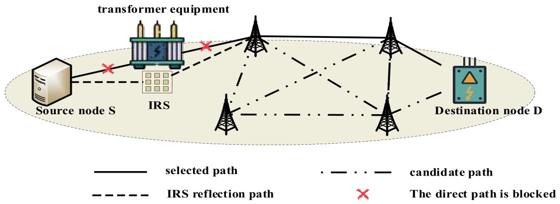
Consider an IRS-assisted multi-hop relay network, suitable for communication scenarios at the distribution substation or industrial park station level within power wireless private networks. The system model is shown in Figure 1. The coverage area is 500 m × 500 m and includes a source node S , a destination node D , K relay nodes R k ( k = 1 , 2 , , K ), and an IRS composed of N passive reflecting elements. The source node S and destination node D correspond to the main grid access point and end-service terminals (such as distribution automation terminals, online monitoring sensors, etc.) within the station, respectively. Relay nodes are deployed at fixed locations such as towers or equipment cabinets, and the node positions remain unchanged during the entire communication process. This reflects the rigid topology of the power grid, eliminating the possibility of dynamic node relocation and forcing resource optimization to rely solely on relay selection, power control, and IRS configuration.
The IRS is deployed on the surface of an obstacle between the source node S and the first-hop relay R 1 , actively participating in signal reflection only during the first-hop transmission to provide reflection enhancement for that link. Subsequent relay links do not rely on IRS assistance, and their channels are considered traditional point-to-point links. The assumption that a single IRS only assists the first hop is due to the practical engineering constraints of the power wireless private network. Transformers, cabinets, walls, and other obstacles are usually densely distributed near the source node, causing serious “first-hop blind spots”. Deploying IRS on these obstacle surfaces is low-cost and easy to maintain, avoiding complex modifications to existing relay nodes. In addition, once the signal bypasses the first obstacle, subsequent jumps usually have a relatively clear line of sight path due to tower lifting, thus reducing the necessity of IRS assistance.
All relay nodes operate in half-duplex decode-and-forward mode, with only the transmitting and receiving nodes of the current hop being active in each time slot. The decision variables for network optimization include relay path selection, transmit power allocation of each node, and IRS phase shift configuration. The optimization objective is to maximize the system energy efficiency while satisfying the QoS constraints of power services.

2.2. Channel and Signal Transmission Model

2.2.1. Path Loss Model

In the power wireless private network, the Okumura–Hata model [28] is selected as the inter-node channel fading model, which is suitable for the 230 MHz frequency band of the power wireless private network. The path loss (in dB) is expressed as
L = 69.55 + 26.16 log 10 f c 13.82 log 10 H b + ( 44.9 6.55 log 10 H b ) log 10 d α ( H r )
where f c denotes the selected operating frequency, H b denotes the height of the transmitting antenna, H r denotes the height of the receiving antenna, d denotes the distance between the transmitter and receiver, and α ( H r ) is the antenna correction factor. In the context of the power wireless private network [28],
α ( H r ) = 8.29 ( log 10 1.54 H r ) 2 1.1

2.2.2. Small-Scale Fading and Channel Coefficients

On the basis of path loss, the channel coefficients incorporate the effects of small-scale fading. The following channels are defined:
h S , R 1 is the direct channel coefficient from the source node S to the first-hop relay R 1 ;
h R k , R k + 1 is the channel coefficient from relay R k to relay R k + 1 ;
h R K , D is the channel coefficient from the last-hop relay node R K to the destination node D ;
h S N × 1 is the channel vector from the source node S to the IRS;
g R 1 N × 1 is the channel vector from the IRS to the first-hop relay R 1 .
The above channel coefficients all include path loss and small-scale fading, i.e.,
h = 10 L ( d ) / 10 h ˜
where h ˜ is a complex random variable with a mean of 0 and a variance of 1, and its envelope follows a Rayleigh or Rician distribution.
To focus on the overall reflection effect of the IRS, it is assumed that its dimensions are much smaller than the distance to the nodes, so that the distances of each reflecting element are approximately equal; meanwhile, the IRS is often deployed in the line-of-sight path, so the channel vectors can adopt the Rician fading model:
h = κ κ + 1 h LoS + 1 κ + 1 h NLoS
where κ is the Rician factor, h LoS is the deterministic line-of-sight component vector, and h NLoS is the random scattered component vector, whose elements follow an independent and identically distributed complex Gaussian distribution C N ( 0 , 1 ) .

2.2.3. IRS Phase Shift Model

The phase shift matrix of an IRS composed of N reconfigurable units is denoted as Θ = diag ( β 1 e j θ 1 , β 2 e j θ 2 , , β N e j θ N ) , where β n [ 0 , 1 ] represents amplitude attenuation and θ n [ 0 , 2 π ) denotes phase shift. For an ideal passive IRS, β n = 1 , each reflective unit satisfies the unit modulus constraint | e j θ n | = 1 , meaning it only changes the signal phase without amplifying or attenuating its amplitude.

2.2.4. Time Slot Division and Equivalent Channel Modeling

The system operates in half-duplex mode. When all K relay nodes are selected, the configuration of transmitting and receiving nodes in each time slot is as follows:
T S 1 : Source node S transmits, and relay R 1 receives;
T S i ( i = 2 , 3 , , K ): Relay R i 1 transmits, and relay R i receives;
T S K + 1 : Relay R K transmits, and destination node D receives.
Since the IRS actively participates in signal reflection only in time slot T S 1 , and does not perform phase adjustment in subsequent time slots (its impact has been included in the statistical characteristics of channel fading), the equivalent channel for each time slot needs to be defined separately:
(1) T S 1
In time slot T S 1 , source node S transmits signals with power P S , while relay R 1 simultaneously receives signals from both the direct path and the IRS-reflected path. The equivalent channel coefficient for T S 1 is
h e q ( 1 ) = h S , R 1 + g R 1 H Θ h S
where H denotes conjugate transpose, and the received signal-to-interference-plus-noise ratio (SINR) is
γ ( 1 ) = P S h eq ( 1 ) 2 σ 2
(2) T S i ( i = 2 , 3 , , K )
In time slot T S i , relay R i 1 forwards the signal to relay R i with power P R i 1 . At this time, the IRS does not participate in active reflection, and the equivalent channel coefficient is determined solely by the direct path between the transmitting and receiving nodes, that is
h eq ( i ) = h R i 1 , R i , i = 2 , 3 , , K
The received SINR is
γ ( i ) = P R i 1 h eq ( i ) 2 σ 2 , i = 2 , 3 , , K
(3) T S K + 1
In time slot T S K + 1 , relay R K forwards the signal to destination node D with power P R K . This time slot also lacks IRS assistance, and the equivalent channel coefficient is
h eq ( K + 1 ) = h R K , D
The received SINR is
γ ( K + 1 ) = P R K h eq ( K + 1 ) 2 σ 2
For decode-and-forward multi-hop relay networks, the end-to-end equivalent SINR is well approximated by the minimum per-hop SINR when the per-hop SINRs are equalized under optimal power allocation or in the medium-to-high SINR regime
γ e 2 e min T S γ ( T S )
Based on the end-to-end SINR, the total transmission rate of the system is
R = B log 2 ( 1 + γ e 2 e )
Here, R denotes the long-term average throughput under pipelined half-duplex transmission. Although Shannon capacity is a theoretical upper bound, it is adopted for fair comparison because all schemes use the same rate model; the relative performance ranking remains valid.

2.3. Key Performance Indicators and Constraints

Based on the aforementioned channel and signal transmission model, this section defines three core performance metrics of the system: latency, reliability, and energy efficiency, and provides corresponding constraints. Assuming the selected multi-hop path comprises M relay nodes ( M K ), the end-to-end transmission involves M + 1 hops.

2.3.1. Latency

The end-to-end delay consists of two parts: the processing delay at relay nodes and the transmission delay of data packets. Let the fixed processing delay of each relay node be t p and the size of the data packet be Q . Then the total delay can be expressed as
t t o t a l = M t p + Q R
Power services are categorized according to IEC 61850 [29]: protection (latency < 4 ms, outage probability below 10 5 ), automation (latency < 16 ms, outage probability below 10 5 ), and metering (latency < 250 ms, outage probability below 10 5 ). Our model targets the most stringent class (protection) and therefore the system must meet
t t o t a l t max
where t max represents the maximum end-to-end delay permitted by the service. As can be seen from Equation (13), the delay performance is directly dependent on two key factors: relay hop count and end-to-end rate. The hop count is determined by the relay selection strategy, while the rate is jointly determined by power allocation and IRS phase shift configuration. Therefore, hop count and rate are the core variables affecting delay.

2.3.2. Reliability

Power control services have extreme requirements for reliability, which are reflected in the constraint on the probability of interruption. The system requires that the probability of the end-to-end SINR being below a certain threshold γ th must be lower than a limit value ε (e.g., outage probability below 10 5 )
Pr ( γ e 2 e < γ th ) ε
Under the deterministic optimization framework of this paper, it can be simplified to a strict SINR threshold constraint in the worst case
γ e 2 e γ th
This constraint ensures that the instantaneous SINR always meets the reliability requirements under a given channel implementation, thereby indirectly guaranteeing the outage probability metric [12]. Unlike civilian networks that often adopt probabilistic QoS (e.g., outage probability averaged over fading), power protection services require deterministic QoS, i.e., the SINR must satisfy the threshold for every channel realization.

2.3.3. Energy Efficiency

With energy efficiency optimization as the core objective, the system energy efficiency is defined as the ratio of total transmission rate to total power consumption. Meanwhile, let the relay selection indicator variable be a k { 0 , 1 } , indicating whether relay node R k is selected. Then, the energy efficiency can be expressed as
η EE = R P total = B log 2 ( 1 + γ e 2 e ) P S + k = 1 K a k P R k + P C
Among them, the total power consumption P total includes the transmission power P S , the transmission power k a k P R k of the selected relay node, and the circuit power consumption P C , which includes the circuit consumption of the relay node and IRS. This definition intuitively reflects the number of information bits that can be transmitted per unit of energy consumed by the system.
In addition, system optimization must also satisfy the following physical resource constraints.

2.3.4. Power Constraints

The transmission power of each node is limited by hardware capabilities.
Source node:
0 P S P S max
Relay node:
0 P R k P R max
Total system power:
P S + k = 1 K a k P R k P total max

2.3.5. IRS Phase Shift Constraint

Each reflection unit must satisfy the unit modulus constraint
| e j θ n | = 1

2.3.6. Relay Selection and Path Constraints

In a multi-hop relay network, it is necessary to select M relays from K candidates to form an acyclic and effective path from the source node to the destination node. Let R = R 1 , R 2 , , R K denote the set of candidate relay nodes, and δ i , j { 0 , 1 } represent whether link i j is selected. Then the path constraint can be expressed as
Outflow constraint:
j S δ S , j = 1
indicating that there is only one link originating from the source node;
Inflow constraint:
i D δ i , D = 1
indicating that there is exactly one link entering the destination node D ;
Flow conservation constraint:
i R k δ i , R k = j R k δ R k , j 1 , R k R
indicating that for any relay node R k , if it is selected, the in-degree equals the out-degree equals 1; otherwise, both are 0. Leveraging the fixed node positions in power wireless private networks, assigning a monotonic order to all nodes along the direction from S to D is sufficient to guarantee acyclicity.
In addition, the relationship between the relay selection indicator variable a k and the link selection variable δ i , j is
a k = i V \ { R k } δ i , R k , k = 1 , 2 , , K

2.3.7. Transmission Rate Constraint

To ensure the basic communication needs of the power business, the end-to-end transmission rate of the system must meet the minimum rate constraint, that is
R R min
Based on the above analysis, the resource coordination optimization problem of IRS-assisted multi-hop relay networks is modeled as a joint optimization problem aimed at maximizing system energy efficiency. The decision variables include the discrete relay selection variable a = a 1 , a 2 , , a K T { 0 , 1 } K × 1 , link selection variable Δ = δ i , j | V | × | V | , continuous power allocation variable P = P s , P R 1 , P R 2 , , P R K T ( K + 1 ) × 1 , and non-convex IRS phase shift variable Θ = diag ( e j θ 1 , e j θ 2 , , e j θ N ) N × N . Finally, the constructed joint optimization problem is as follows:
max a , Δ , P , Θ η EE = R P total = B log 2 ( 1 + γ e 2 e ) P S + k = 1 K a k P R k + P C s . t .   Equations   ( 14 ) , ( 16 ) , ( 18 ) ( 26 )
Equation (27) falls within the category of mixed-integer non-convex optimization. The objective function exhibits a fractional structure, and the constraints encompass both discrete variables and unit-modulus non-convex constraints, rendering direct solution challenging. Theorem 1 provides a guarantee for the existence of an optimal solution to this problem.
Theorem 1.
For the given parameters B , σ 2 , P S max , P R max , R min , γ th , P total max , t max , the maximum value of the objective function in Equation (27) must exist.
Proof of Theorem 1.
See Appendix A for details. □

3. Algorithm Design and Implementation

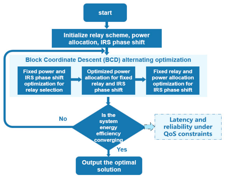
For the mixed-integer non-convex optimization problem constructed in Chapter 2, directly solving it would result in an excessively large computational burden. To address this, the BCD framework is introduced, decomposing the originally complex joint optimization into three more manageable subproblems: relay selection, power allocation, and IRS phase shift configuration. By iteratively optimizing these three sub-modules, we gradually approach the global optimal solution.
The overall flow of the algorithm is shown in Figure 2. Its core idea is to fix two variable blocks in each iteration and optimize the third variable block, repeating this process until convergence is reached.

3.1. Relay Selection Based on Greedy Algorithm

Given that the BCD framework requires multiple iterations, the computational efficiency of the relay selection subproblem directly constrains the overall convergence speed. Compared to high-complexity algorithms such as global search, greedy algorithms are more suitable for quickly constructing effective multi-hop paths within this framework due to their low computational cost and simple implementation.
Under the BCD framework, the relay selection subproblem requires the rapid selection of an end-to-end multi-hop path P from the source node S to the destination node D from a set of candidate relay nodes R = R 1 , R 2 , , R K , under the conditions of fixed power allocation P and IRS phase shift configuration Θ , in order to maximize system energy efficiency. The relay selection subproblem can be expressed as follows:
max a , Δ η E E = R ( a , Δ ) P total ( a ) s . t .   Equation   ( 22 ) ( 25 )
Defining the link quality cost of node j for the current partial path P part as the basis for greedy selection,
Γ i j = γ i j P i + P c
where i is the last node of the current path, j is the candidate node, and γ i j is the SINR of link i j , which is calculated based on the fixed power vector P and the fixed IRS phase shift matrix Θ . This metric comprehensively considers both link quality and energy consumption cost, favoring the selection of nodes with good channel conditions and relatively low energy consumption. The specific process of the algorithm is shown in Algorithm 1.
Algorithm 1. Greedy relay selection algorithm
Inputs:
  • Source node S , destination node D , candidate relay node set R , fixed power allocation vector P , fixed IRS phase shift matrix Θ , minimum SINR threshold γ th .
Outputs:
 Relay selection vector a and link selection matrix Δ
Procedure:
  • Initialize   the   current   path   P = S , the set of unvisited nodes H = R , and the temporary disabled list T =
  • While   the   last   node   of   the   current   path   D do:
  •     Let i be the last node of path P
  •      Filter   candidate   node   set   C = k H γ i j γ th from H
  •      If   C =
  •       If   P = S
  •         Algorithm failed, returning an empty path
  •         else
  •           Undo: Remove i from P and add it to T
  •     else
  •        For   each   k C , calculate the link quality cost ratio compared to Γ i j
  •        Select   the   optimal   candidate   node   k * = arg max k C Γ i j
  •      Update   the   path   and   node   sets   P = P k * and H = H \ k *
  •     end if
  • end while
  • Update the relay selection vector a and the link selection matrix Δ based on the final path P
The greedy algorithm backtracks when a selected relay leads to a dead end: it removes that relay, disables it temporarily, and resumes from the previous node. Termination occurs successfully when the destination is reached, or with failure (empty path) when backtracking exhausts all options. With at most six relays, the worst-case complexity is O M 2 . An empty path triggers re-routing or QoS relaxation in the outer BCD loop.

3.2. Power Allocation Based on Dinkelbach and Lagrange Multiplier Method

Under the BCD framework, the power allocation subproblem requires optimizing the transmit power of the source node and each relay node under the condition of fixed relay selection vector a and IRS matrix Θ , in order to maximize system energy efficiency. To simplify notation, the transmit power of each hop is denoted as P 0 = P S , P m = P R m ( m = 1 , 2 , , M ), respectively, and the power vector is denoted as P = P 0 , P 1 , P 2 , , P M T .
After selecting fixed relay a and IRS phase shift matrix Θ , the power allocation subproblem can be expressed as
max P η E E = R ( P ) P total ( P ) s . t . 0 P m P max , m = 0 , , M m = 0 M P m P total max γ e 2 e ( P ) γ th R R min
This is a typical fractional programming problem, which is transformed into an equivalent parameterized problem using the Dinkelbach method. By introducing an auxiliary parameter q , the function can be defined as follows:
F ( q ) = max P F R ( P ) q P total ( P )
where F represents the feasible region defined by the power constraint in Equation (30).
The core theorem of the Dinkelbach method states that the corresponding q is the optimal energy efficiency value of the original problem if and only if F ( q ) = 0 , and the P that achieves this value is the optimal power allocation [30]. Based on this, power allocation can be solved alternately through outer Dinkelbach iteration and the inner maximization problem. The outer iteration updates the value of q , while the inner maximization problem in Equation (31) is solved under a given q .
When q is given, the inner problem is
max P f ( P ) = B log 2 1 + γ e 2 e ( P ) q m = 0 M P m s . t . 0 P m P max , m = 0 , , M m = 0 M P m P total max γ e 2 e ( P ) max γ th , 2 R min / B 1 γ min
The minimum rate constraint and the SINR threshold constraint have been consolidated into a unified lower bound for the SINR, which is defined as the pointwise minimum SINR across all hops. At the point of optimal power allocation, the SINR values for all selected links should generally be equal [12]. If this is not the case, the total power consumption can be decreased without compromising the data rate by reducing the power allocated to non-bottleneck links. Hence, at the optimal solution, it is observed that
γ ( 1 ) = γ ( 2 ) = = γ ( M + 1 ) = γ γ min
Substituting the expressions for the SINR of each hop into Equation (33) yields the proportional relationship between the powers. Define the equivalent channel gain as
G 1 = h S , R 1 + g R 1 H Θ h S 2 σ 2 G m = h R m 1 , R m 2 σ 2 , m = 2 , , M + 1
Then γ ( 1 ) = P 0 G 1 , γ ( m ) = P m 1 G m , and from Equation (33) we obtain
P 0 G 1 = P 1 G 2 = = P M G M + 1 = γ
From this, each power can be expressed as a function of γ :
P 0 = γ G 1 , P m = γ G m + 1 , m = 1 , , M
At this point, the total power consumption can be denoted as P total = γ m = 0 M 1 / G m + 1 + P c , and the inner-level Equation (32) degenerates into an optimization problem involving a single variable γ :
max γ   B log 2 ( 1 + γ ) q γ m = 0 M 1 G m + 1 s . t . γ γ min γ G m + 1 P max , m = 0 , , M γ m = 0 M 1 G m + 1 P total max P c
Take the derivative of the objective function with respect to γ , and set the derivative to zero to obtain the unconstrained optimal solution. The objective function is
g ( γ ) = B log 2 ( 1 + γ ) q γ A
where A = m = 0 M 1 / G m + 1 , let g ( γ ) = 0 ; then
B ( 1 + γ ) ln 2 q A = 0 γ opt = B q A ln 2 1
Taking into account the constraints in Equation (37), the optimal γ * needs to be projected into the feasible region. The upper bound of γ is determined by the combined power constraints γ ub = min min m P max G m + 1 , ( P total max P c ) / A , while the lower bound is γ lb = γ min . Therefore, the optimal solution is
γ * = max γ lb , min γ opt , γ ub
After obtaining γ * , the transmit power of each node is given by Equation (36), and further truncation is required to satisfy the upper and lower bounds of power. After truncation, the per-hop SINRs are re-evaluated. If any hop violates γ min , the truncated solution is discarded and the power allocation subproblem is declared infeasible for the current relay selection and IRS configuration. The objective function in Equation (38) is strictly concave in γ (its second derivative is negative). Hence, the unconstrained maximizer γ * is unique, and the constrained optimum is obtained by projecting γ * onto the feasible interval. This projection preserves optimality because the objective is monotonic outside the interval. The final closed-form solution for power allocation is
P m * = min P max , max 0 , γ * G m + 1 , m = 0 , 1 , , M
If γ lb > γ ub , then Equation (37) has no feasible solution, and the QoS constraints cannot be met under the current relay selection and IRS configuration. Based on the above derivation, the algorithm for solving the power allocation subproblem is as follows. The specific process of the algorithm is shown in Algorithm 2.
Algorithm 2. Power allocation algorithm based on Dinkelbach
Inputs:
  • Selected relay sequence R 1 , R 2 , , R M , fixed IRS phase shift matrix Θ , channel gain G 1 , G 2 , , G M + 1 , system parameters B , σ 2 , P c , P max ( P S max , P R m max ) , P t o t a l max , R min , γ th , convergence accuracy ε .
Outputs:
  • The most power-efficient allocation P * or indicate that there is no feasible solution.
Procedure:
  • Initialization :   Calculate   A = m = 0 M 1 / G m + 1 , γ min , γ ub . If γ min > γ ub , return "No feasible solution.".
  • Set   q 0 = 0 ,   n = 0 , maximum iteration count 50
  •     Repeat
  •       Calculate   γ opt = B q ( n ) A ln 2 1
  •       Calculate   γ * = max γ lb , min γ opt , γ ub
  •       Calculate   the   powers   P m = γ * / G m + 1 according to Equation (36)
  •       Update q ( n + 1 ) = B log 2 ( 1 + γ * ) / m = 0 M P m + P c
  •       n = n + 1
  •      Until   q n q n 1 < ε or n > 50
  •    Return   P * = P 0 , P 1 , P 2 , , P M T
When γ min γ ub , there exists at least one set of power allocation that satisfies all constraints. In this case, Algorithm 2 must return a feasible solution. If infeasibility occurs, it is necessary to backtrack to the relay selection module for rerouting, or appropriately reduce QoS requirements.
The Dinkelbach method iteratively updates an auxiliary parameter q (outer loop). For each fixed q , the fractional objective is transformed into a parametric form, and the optimal power allocation is obtained in closed form via Equations (36)–(41). Thus, the overall power allocation algorithm consists of an outer Dinkelbach iteration and an inner closed-form power update.

3.3. IRS Phase Shift Configuration Based on Closed-Form Solution

From the preceding system model, it can be seen that the IRS is only deployed between the source node S and the first-hop relay R 1 . Its phase shift matrix Θ only affects the equivalent channel gain of the first-hop link and has no effect on subsequent-hop links. Therefore, under the premise that relay selection and power allocation are fixed, the end-to-end SINR γ e 2 e depends on Θ only when the first-hop link is the bottleneck. If the SINR of the first hop is already higher than that of other hops, further optimizing the IRS phase shift cannot improve γ e 2 e , thus having no effect on energy efficiency. Therefore, the reasonable goal of IRS phase shift optimization is to maximize the received SINR γ ( 1 ) of the first-hop link. According to Equation (8), the SINR of the first hop can be written as
γ ( 1 ) = P S h S , R 1 + g R 1 H Θ h S 2 σ 2
The subproblem of IRS phase shift configuration can be expressed as
max Θ   γ ( 1 ) ( Θ ) s . t .   Θ = diag e j θ 1 , , e j θ N θ n [ 0 , 2 π ) , n = 1 , , N
Expanding Equation (42) to g R 1 H Θ h S = n = 1 N g n * h n e j θ n , where g n and h n represent the n -th element of channel vectors g R 1 and h S , respectively. Then, the SINR of the first hop is proportional to h S , R 1 + n = 1 N g n * h n e j θ n 2 .
From the triangle inequality, it can be seen that the aforementioned modulus reaches its maximum when all phases are consistent. Specifically, let the direct path phase be ϕ 0 = h S , R 1 , and let the equivalent channel phase introduced by the IRS reflection unit in the n -th reflection path be ϕ n = g n * h n . In order to make all reflected signals superimpose in phase with the direct signal at the receiving end, the phase shift θ n of the n -th unit of the IRS should be adjusted to compensate for the phase delay of this path, that is
θ n * = ϕ 0 ϕ n = h S , R 1 g n * h n , n = 1 , 2 , , N
Although the direct link may be severely attenuated by obstacles, a weak direct path still exists under the Rician fading model, providing a well-defined phase reference for IRS alignment. In the extreme case of complete blockage, aligning the IRS phases to a common reference is equally valid, because only relative phases matter. Consequently, the signals from each reflection path are aligned in phase with the direct signal, resulting in the maximum amplitude of the received signal:
h S , R 1 + n = 1 N g n * h n e j θ n * = h S , R 1 + n = 1 N g n * h n
The corresponding maximum first-hop SINR is
γ max ( 1 ) = P S σ 2 h S , R 1 + n = 1 N g n h n 2
Equation (44) provides a closed-form expression for the optimal phase shift of each reflection unit in the IRS. This solution relies solely on the phase information of channel state information and can obtain the global optimal solution without iteration. The specific process of the algorithm is shown in Algorithm 3.
Algorithm 3. IRS phase shift configuration algorithm
Inputs:
 Channel coefficient h S , R 1 , h S , g R 1 , IRS element number N
Outputs:
 Optimal phase shift matrix Θ *
Procedure:
  • Calculate   the   direct   path   phase   ϕ 0 = h S , R 1
  • For   n = 1 to N do
  •      Calculate   the   equivalent   reflected   channel   phase ϕ n = g n * h n
  •     Calculate the optimal phase shift for the n -th unit θ n * = ϕ 0 ϕ n
  •     end for
  •      construction   Θ * = diag e j θ 1 * , , e j θ N *
  •      return   Θ *
In the proposed BCD framework, each subproblem is solved in a way that does not decrease the objective function η EE . Specifically, Algorithm 1 picks the best available relay under fixed power and IRS phases, so η EE either increases or stays the same. Algorithm 2 is known to monotonically increase η EE [30]. Algorithm 3 maximizes the first-hop SINR, which does not reduce the end-to-end rate and hence does not reduce η EE . Therefore, the sequence η EE m generated by the algorithm is non-decreasing. Moreover, Theorem 1 guarantees that η EE is upper-bounded under the given constraints. A non-decreasing and upper-bounded sequence always converges to a finite limit. Hence, the proposed algorithm is guaranteed to converge.
The complexity of each BCD subproblem is as follows. Greedy relay selection with backtracking costs O ( M 2 )   ( M 6 ) . Dinkelbach power allocation costs O ( I D M ) , where I D < 10 and M is the number of hops. IRS phase alignment costs O ( N )   ( N = 64 ) . The overall BCD complexity is O I BCD M 2 + I D M + N with I BCD 50 , which is manageable for real-time power communication.

4. Case Implementation and Analysis

4.1. Parameter Setting and Initialization

To evaluate the performance of the BCD-Joint optimization algorithm proposed in this paper, multiple sets of simulation experiments are designed in this section. By comparing with various benchmark algorithms, the performance of the proposed algorithm in an IRS-assisted multi-hop relay network is assessed based on three core performance metrics: system energy efficiency, outage probability, and average delay.
The simulation scenario is a 500 m × 500 m rectangular area, representing a distribution substation or industrial park core area. The source node is fixed at (0,250) m, the destination node at (500,250) m, and six relay nodes are randomly but statically placed within [(50,150), (450,350)] with a fixed random seed (0). The IRS is deployed on an obstacle surface between the source and the first-hop relay to address the “first-hop blind spot”. The 230 MHz carrier frequency and Okumura–Hata path loss model comply with standard power private network specifications. The per-relay processing delay is 1 ms (based on field measurements), and the IRS has 64 reflecting units. For each parameter set, 10,000 independent Monte Carlo trials are performed. The outage probability is computed as the ratio of trials where the end-to-end SINR falls below γ th over the total number of trials. IRS phase shifts are assumed continuously adjustable (no discretization), as practical IRSs achieve fine phase control. The remaining key parameters are listed in Table 1.
The initialization process of the joint optimization algorithm based on the BCD framework proposed in this paper is as follows: the IRS phase shift randomly generates a set of initial values satisfying the unit modulus constraint [18]; the power allocation adopts a uniform allocation strategy, allocating initial transmit power to each node under the total power constraint; the relay selection subproblem is solved based on the current power and IRS phase shift, thus no initial path needs to be specified in advance. The number of iterations refers to the typical setting of the alternating optimization algorithm in the literature [22], ensuring convergence accuracy while also considering computational efficiency. All power values in dBm are converted to watts using P W = 10 ( P dBm 30 ) / 10 before calculations.
To evaluate the individual contributions of IRS, relay selection, and power allocation, we compare BCD-Joint with three complementary baselines: No-IRS (same relay selection and power control but without IRS), Dijkstra-Relay (IRS and Dinkelbach power control kept, greedy relay selection replaced by the classical Dijkstra shortest-path algorithm with path-loss edge weights, as in [31]), and Equal-Power (EPA) (IRS and greedy relay selection kept, Dinkelbach power control replaced by uniform power distribution among all transmitting nodes, which is a standard non-adaptive baseline [32]). By contrasting BCD-Joint with these baselines, we isolate the necessity of IRS, the effectiveness of greedy relay selection, and the advantage of Dinkelbach power control, respectively.

4.2. Simulation Results and Analysis

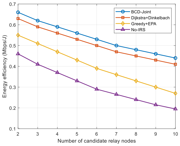
Figure 3 illustrates the variation of system energy efficiency with the number of candidate relay nodes (network size) under different algorithms. As the number of candidate relays increases, the greedy relay selection tends to construct longer paths (i.e., selects more relays) to satisfy the QoS constraints. Under the fixed transmit power, distributing power over more hops reduces the per-hop SINR and the end-to-end rate, leading to lower energy efficiency. The proposed BCD-Joint algorithm consistently achieves the highest energy efficiency across all network sizes. For instance, when there are six candidate relays, BCD-Joint yields an energy efficiency of 0.53 Mbps/J, which is 6% higher than Dijkstra+Dinkelbach, 36% higher than Greedy+EPA, and 83% higher than No-IRS. These results validate the necessity of the IRS, the benefit of greedy relay selection, and the advantage of Dinkelbach-based power control. The performance gap becomes more pronounced as the network size increases, indicating that the joint optimization is particularly effective in dense relay deployment.
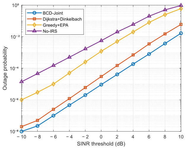
Figure 4 shows the outage probability versus the SINR threshold under different algorithms. As the SINR threshold increases, all curves rise steeply on the logarithmic scale because higher reliability requirements demand better channel conditions. The BCD-Joint algorithm consistently exhibits the lowest outage probability, followed by Dijkstra+Dinkelbach, Greedy+EPA, and No-IRS. For example, at an SINR threshold of 0 dB, the outage probabilities of BCD-Joint, Dijkstra+Dinkelbach, Greedy+EPA, and No-IRS are approximately 9.2 × 10⁻⁶, 3.0 × 10⁻⁵, 1.2 × 10⁻³, and 5.6 × 10⁻³, respectively. The substantial reduction achieved by BCD-Joint confirms that the combination of IRS phase alignment, energy-efficient power control, and adaptive relay selection significantly improves link reliability, even under stringent QoS constraints. Notably, the gap between BCD-Joint and Greedy+EPA widens as the SINR threshold increases, indicating that the Dinkelbach power control becomes increasingly critical when high link quality is required. Furthermore, the difference between the IRS-assisted schemes (BCD-Joint, Dijkstra+Dinkelbach, Greedy+EPA), and No-IRS demonstrates the essential role of IRS in mitigating the “first-hop blind spot”, which is the primary source of outage in power wireless private networks.
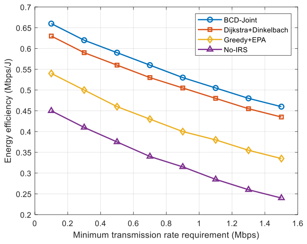
Figure 5 illustrates the energy efficiency versus the minimum transmission rate requirement. For all algorithms, energy efficiency decreases as the rate requirement increases, because higher rates require higher transmit power following a logarithmic Shannon relationship. The BCD-Joint algorithm maintains the highest energy efficiency across the entire range. When R min = 1   Mbps , BCD-Joint achieves 0.52 Mbps/J, which is 9% higher than Dijkstra+Dinkelbach, 37% higher than Greedy+EPA, and 73% higher than No-IRS. Moreover, the performance gap widens with increasing rate requirements, demonstrating that the proposed joint optimization is particularly beneficial for high-rate services. This is because BCD-Joint’s greedy relay selection avoids weak links that would otherwise require excessive power to meet high rate demands, while Dinkelbach power control ensures that power is allocated only where it is most effective. In contrast, Greedy+EPA wastes power on all links equally, and No-IRS suffers from poor first-hop signal quality, both leading to a faster decline in energy efficiency as the rate requirement becomes more demanding.
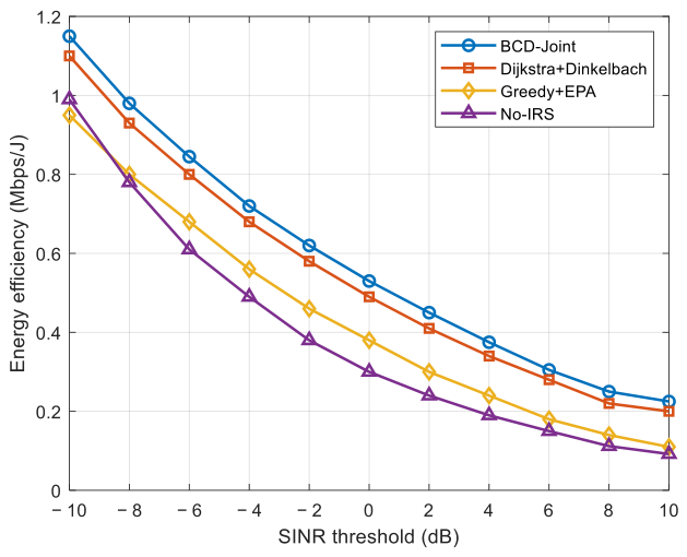
Figure 6 depicts the energy efficiency as a function of the SINR threshold. As the required SINR increases, all schemes suffer from decreasing energy efficiency because more transmit power is needed to meet the stricter link quality. The BCD-Joint algorithm consistently outperforms the three baselines. When γ th = 0 dB, the energy efficiencies of BCD-Joint, Dijkstra+Dinkelbach, Greedy+EPA, and No-IRS are 0.52, 0.49, 0.38, and 0.30 Mbps/J, respectively. Notably, the advantage of BCD-Joint over Greedy-EPA becomes more significant at higher SINR thresholds, highlighting the crucial role of Dinkelbach-based power control in maintaining energy efficiency under high-reliability requirements. The IRS also contributes substantially, as seen by the large gap between No-IRS and the IRS-assisted schemes. For instance, when γ th = 4 dB, the energy efficiency of BCD-Joint is 0.38 Mbps/J, while No-IRS is only 0.19 Mbps/J—a relative improvement of nearly 100%. This demonstrates that IRS phase alignment not only reduces outage probability but also directly improves energy efficiency by increasing the effective SINR of the first hop without extra transmit power.
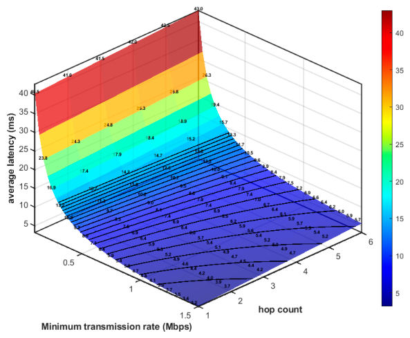
Figure 7 shows the average delay of the BCD-Joint algorithm as a function of the minimum transmission rate and relay hop count in three-dimensional curved form. From the graph, it can be seen that when R min = 0.5   Mbps and the number of relay hops M = 3 , the delay is about 9.5 ms; when R min = 1   Mbps and the number of relay hops M = 3 , the delay is about 5 ms; when R min = 0.5   Mbps and the number of relay hops M = 5 , the delay is about 10.5 ms. The end-to-end delay depends on both processing delay and transmission delay. The trend of three-dimensional surfaces indicates that in low-speed regions, transmission delay dominates, and delay decreases rapidly with increasing speed; in high-speed regions, processing latency becomes the main component, and latency increases linearly with hop count. The BCD-Joint algorithm controls the number of hops through relay selection, and combines power and IRS optimization to improve transmission rate, placing the system in a favorable area of “low hop count, high rate”, thereby controlling latency in milliseconds and meeting the strict requirements of power services for latency.
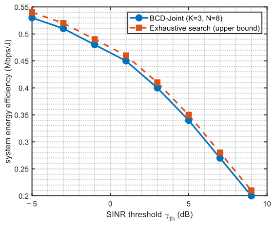
Figure 8 compares the performance upper bound of the BCD-Joint algorithm proposed in this paper with grid search benchmark in small-scale scenarios (candidate relay K = 3 , IRS reflection unit N = 8 ). The grid search enumerates all possible relay paths and discretizes the transmit power with a 1 dBm step and the IRS phase with π / 4 discrete steps. This grid search provides an approximate reference rather than a true global optimum, due to the discretization of continuous variables. As shown in the figure, the energy efficiency of BCD-Joint is highly consistent with this grid search benchmark at different SINR thresholds (average deviation < 3%), indicating that the proposed algorithm can effectively approximate the benchmark solution in this small-scale scenario.
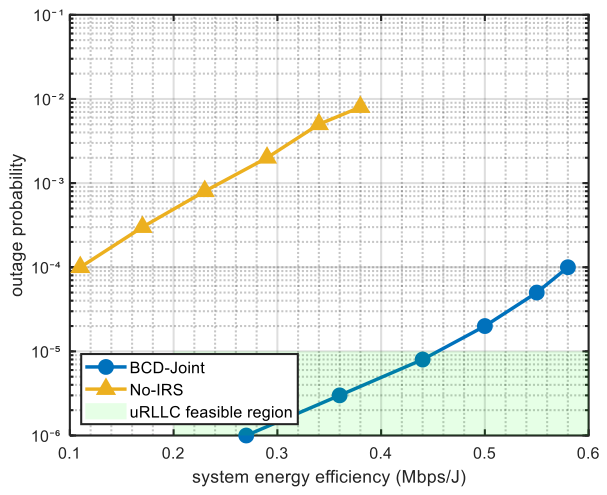
Figure 9 shows the energy efficiency outage probability relationship between the BCD-Joint algorithm proposed in this paper and the No-IRS benchmark scheme. Each point on the curve corresponds to the optimal operating point under different minimum transmission rate constraints. The green shaded area represents the typical feasible region of the power URLLC business. By comparison, it can be seen that under the same outage probability requirement, the BCD-Joint algorithm can achieve higher energy efficiency; at the same energy efficiency level, its reliability is significantly better than the No-IRS scheme. It is almost impossible for the No-IRS scheme to enter the feasible region of URLLC, while the BCD-Joint algorithm can maintain high energy efficiency while meeting extreme reliability requirements, verifying the dual gain of IRS introduction and joint optimization on system performance.

5. Conclusions

This study focuses on the energy efficiency optimization problem of power wireless private networks under extreme service quality constraints, and proposes a multi-hop relay network resource optimization method based on intelligent reflector assistance. A hybrid multi-hop relay system model with IRS-enhanced first-hop link was constructed to address the problem of the “first-hop blind spot” caused by internal obstruction in power plants, making the scene setting more realistic in engineering. On this basis, the joint optimization problem of relay selection, power allocation, and IRS phase shift configuration is modeled as a mixed-integer non-convex programming, and is decomposed into three subproblems for alternating solution based on the block coordinate descent framework. Differently from traditional iterative algorithms, this paper derives closed-form solutions for power allocation and IRS phase shift optimization subproblems, significantly reducing computational complexity. In addition, comparison with the grid search benchmark in a small-scale scenario shows that BCD-Joint can effectively approximate the benchmark solution (within 3% deviation), supporting its practical effectiveness. The simulation results show that the proposed method outperforms benchmark schemes such as No-IRS, random IRS, and fixed relay in terms of system energy efficiency, outage probability, and delay control. The Pareto frontier analysis of energy efficiency and reliability reveals a significant expansion of the system performance boundary by introducing IRS.
Although this paper assumes a single IRS assisting only the first hop, the proposed BCD framework is modular and extensible. For multiple IRSs assisting multiple hops, additional phase shift subproblems can be added, each solved by the same closed-form phase alignment principle. Relay selection and power allocation remain unchanged except that the equivalent channel gains incorporate the optimized IRS reflections. Our algorithm also supports multi-IRS cooperation by sequentially optimizing each IRS’s phases while fixing others. Thus, this work provides a foundational module for richer IRS-assisted multi-hop networks in future power communication systems. The study assumes fixed topology and ideal CSI, and is validated by simulations only. In the future, further research will be conducted on adaptive optimization strategies in dynamic channel environments and exploring distributed IRS collaborative architectures to enhance the flexibility of network coverage, while introducing intelligent methods such as deep reinforcement learning to enhance the robustness and real-time decision-making ability of the system in uncertain environments, in order to adapt to more complex power communication scenarios.


Author Contributions

Conceptualization, L.W.; methodology, L.W.; software, L.W. and Y.W.; validation, Y.W. and G.X.; formal analysis, Y.W.; investigation, Y.W.; resources, G.X.; data curation, Y.W.; writing—original draft preparation, L.W. and Y.W.; writing—review and editing, L.W. and G.X.; visualization, L.W.; supervision, G.X.; project administration, G.X.; funding acquisition, G.X. All authors have read and agreed to the published version of the manuscript.

Funding

This research was supported by the State Grid Corporation of China Science and Technology Project “Research on Multi-Mode Networking and Unified Control Technology Based on Power Wireless Private Network” (Grant No. 5700-202424260A-1-1-ZN).

Data Availability Statement

Data and supportive studies are contained within this article.

Conflicts of Interest

The authors declare that the research was conducted in the absence of any commercial or financial relationships that could be construed as a potential conflict of interest.

Abbreviations

The following abbreviations are used in this manuscript:
QoSQuality of Service
IRSIntelligent Reflecting Surface
URLLCUltra-Reliable and Low-Latency Communication
MIMOMultiple-Input–Multiple-Output
BCDBlock Coordinate Descent
SINRSignal-to-Interference-plus-Noise Ratio

Appendix A. Proof of the Existence of the Maximum Value of a Function

Proof. 
The decision variables for Equation (27) include discrete relay selection variable a = a 1 , a 2 , , a K T and link selection variable Δ = δ i , j | V | × | V | , continuous power allocation variable P = P s , P R 1 , P R 2 , , P R K T , and IRS phase shift variable Θ = diag ( e j θ 1 , e j θ 2 , , e j θ N ) . The properties of the feasible region are analyzed below. □
  • The Feasible Range of Relay Selection Variables
Relay selection variable a k { 0 , 1 } and link selection variable δ i , j { 0 , 1 } must satisfy path validity constraints Equations (22)–(25). Due to the limited number of candidate relay nodes K in the network, all possible relay selection combinations form a finite set. If the finite set is A , then A 2 K 2 ν 2 < .
  • Feasible Range of Power Variables
For any fixed relay selection, the power variable P needs to satisfy Equations (18)–(20). These constraints define a bounded closed set (polyhedron) in M + 1 -dimensional Euclidean space, denoted as P a .
P a = P M + 1 | 0 P m P max , m = 0 M P m P total max P c
Among them, P max is P S max for the source node and P R max for the relay. Obviously, P a is a compact set (bounded closed set).
  • The Feasible Range of IRS Phase Shift Variables
The IRS phase shift variable θ n [ 0 , 2 π ) must satisfy the unit modulus constraint | e j θ n | = 1 . Therefore, the phase shift vector θ 1 , , θ N T T N is located on the Cartesian product of N circles, where T = [ 0 , 2 π ) is a one-dimensional circle. Since T N is a compact manifold, the feasible region of the IRS phase shift variable is a compact set.
  • The Compactness of the Overall Feasible Region
For any fixed relay selection ( a , Δ ) A , the corresponding feasible subset is
F ( a , Δ ) = ( P , Θ ) | P P a , Θ T N
Since both P a and T N are compact sets, their Cartesian product A ( a , Δ ) is also a compact set. The overall feasible domain is the union of a finite number of compact subsets
F = ( a , Δ ) A F ( a , Δ )
The union of a finite number of compact sets remains a compact set; therefore F is compact.
  • Continuity of the Objective Function
For any fixed relay selection, the end-to-end rate R is given by Equation (12), where the end-to-end SINR γ e 2 e min T S γ ( T S ) . According to Section 2.2, the first-hop SINR is a continuous function of power γ ( 1 ) , power P S , and phase shift Θ , and the subsequent hop SINR γ ( m ) is a continuous function of power P R m 1 . The minimum operation is a continuous function, and the logarithmic function is also continuous, so R is a continuous function of ( a , Δ ) on F ( a , Δ ) .
The total power consumption P t o t a l is a linear function of the power variable P , clearly continuous. Due to P t o t a l P c > 0 , the objective function η E E = R / P total is a continuous function on F ( a , Δ ) .
  • Existence of Maximum Value
For every fixed continuous function ( a , Δ ) A , η E E must be able to reach its maximum value on the compact set F ( a , Δ ) (according to the extremum theorem). Let the maximum value be η E E ( a , Δ ) . Since A is a finite set, the global maximum value is
η * E E = max ( a , Δ ) A η E E ( a , Δ )
The maximum value in a finite number of real numbers must exist. Therefore, the maximum value of the objective function in Equation (27) must exist. □

References

  1. Zheng, C.; Wu, X.; Li, X.; Chen, J.; Lin, Z.; Xiao, Z.; Liu, H. Development of a 230MHz Interference Source Identification Device for Power Wireless Private Networks. Procedia Comput. Sci. 2022, 203, 350–355. [Google Scholar] [CrossRef] [Scilit]
  2. Zhao, X.; Gan, J.; Xu, W.; Huang, T. A Covariance Matrix-Based Cooperative Spectrum Sensing Algorithm in Electric Wireless Private Network. Mob. Inf. Syst. 2022, 2022, 1420539. [Google Scholar] [CrossRef] [Scilit]
  3. Hu, S.; Chen, X.; Ni, W.; Wang, X.; Hossain, E. Modeling and analysis of energy harvesting and smart grid-powered wireless communication networks: A contemporary survey. IEEE Trans. Green Commun. Netw. 2020, 4, 461–496. [Google Scholar] [CrossRef] [Scilit]
  4. Ma, Y.; Ni, J.; Zhang, X.R. Application of Wireless Communication Technology in Private Power Communication Network. China Broadband 2023, 19, 95–97. (In Chinese) [Google Scholar]
  5. Zhu, X.Q.; Tian, J.; Chen, W.J. State Grid Jiangsu Electric Power Achieves Broadband Data Wireless Multi-hop Reliable Transmission. State Grid News, 12 April 2022; (In Chinese). [CrossRef] [Scilit]
  6. Disaster Investigation Team of the State Council. Investigation Report on the “7·20” Extreme Rainstorm Disaster in Zhengzhou, Henan Province; Report; Ministry of Emergency Management: Beijing, China, 2022. (In Chinese) [Google Scholar]
  7. Kravchuk, S.; Afanasieva, L. “Best” Relay Selection Algorithm for Wireless Networks with Cooperative Relaying. In Proceedings of the 2019 International Conference on Information and Telecommunication Technologies and Radio Electronics (UkrMiCo), Odessa, Ukraine, 9–13 September 2019; pp. 1–4. [Google Scholar]
  8. Basak, S.; Acharya, T. Spectrum-aware Outage Minimizing Cooperative Routing in Cognitive Radio Sensor Networks. Wirel. Netw. 2020, 26, 1069–1084. [Google Scholar]
  9. Li, Q.L.; Dou, Z.; Li, Z.G.; He, Q.H. Adaptive Relay Selection Algorithm for Maritime Multi-hop Communication Networks. In Proceedings of the 2022 National Microwave and Millimeter Wave Conference (Volume II), Harbin, China, 12 August 2022; Conference Paper; China Institute of Electronics: Beijing, China, 2022. (In Chinese) [Google Scholar] [CrossRef]
  10. Ji, B.F.; Yang, J.; Wang, Y.D.; Hu, Y.; Li, C.G.; Song, L. Power Allocation Algorithm for Two-hop Relay Networks Based on Energy Efficiency Optimal Criterion. J. Commun. 2016, 37, 124–131. (In Chinese) [Google Scholar]
  11. Jia, Y.Y.; Xie, Z.J.; Jing, Z. Low Energy Consumption Power Control and Distributed Scheduling Algorithm for Wireless Body Area Networks. Transducer Microsyst. Technol. 2018, 37, 124–128. (In Chinese) [Google Scholar] [CrossRef]
  12. Wang, X.; Jin, T.; Qian, Z.H.; Hu, L.S.; Wang, X. Research on Energy Efficiency Optimization Algorithm for D2D Relay-assisted Communication. J. Commun. 2020, 41, 71–79. (In Chinese) [Google Scholar]
  13. Zhang, S.B.; Chen, C.; Li, Y. Power Control Algorithm for Multi-hop Relay Communication System Based on Energy Efficiency and Delay. J. Nanjing Univ. Posts Telecommun. (Nat. Sci. Ed.) 2021, 41, 1–8. (In Chinese) [Google Scholar] [CrossRef]
  14. Hui, H.; Zhang, Y.; Li, Q. Relay Selection and Power Allocation Algorithm Based on Partial Channel Information. Comput. Eng. 2014, 40, 109–113. (In Chinese) [Google Scholar]
  15. Zhao, Y.; Fang, X.M.; Huang, B.; Chen, Y. Resource Allocation Strategy for OFDMA Two-hop Relay Networks Based on Load Balancing. J. Southwest Jiaotong Univ. 2013, 48, 94–101. (In Chinese) [Google Scholar]
  16. Di Renzo, M.; Zappone, A.; Debbah, M.; Alouini, M.-S.; Yuen, C.; de Rosny, J.; Tretyakov, S. Smart Radio Environments Empowered by Reconfigurable Intelligent Surfaces: How It Works, State of Research, and the Road Ahead. IEEE J. Sel. Areas Commun. 2020, 38, 2450–2525. [Google Scholar] [CrossRef] [Scilit]
  17. Zhou, Y.; Lan, T.Y. A Review of Intelligent Reflecting Surface Research in Wireless Communication Systems. J. Inf. Eng. Univ. 2021, 22, 277–282. (In Chinese) [Google Scholar]
  18. Zhong, K.; Hu, J.; Li, H.; Wang, R.; An, D.; Zhu, G.; Teh, K.C.; Pan, C.; Eldar, Y.C. IRS-aided Beamforming Design for MIMO Systems via Unified Manifold Optimization. IEEE Trans. Veh. Technol. 2024, 74, 674–685. [Google Scholar]
  19. De Souza, W.; Guerra, D.W.M.; Marinello Filho, J.C.; Abrão, T.; Hossain, E. Manifold-based Optimizations for IRS-aided Massive MIMO Systems. IEEE Open J. Commun. Soc. 2024, 5, 7913–7940. [Google Scholar] [CrossRef] [Scilit]
  20. Munochiveyi, M.; Pogaku, A.C.; Do, D.-T.; Le, A.-T.; Voznak, M.; Nguyen, N.D. Reconfigurable Intelligent Surface Aided Multi-user Communications: State-of-the-Art Techniques and Open Issues. IEEE Access 2021, 9, 118584–118605. [Google Scholar]
  21. Zheng, B.; You, C.; Mei, W.; Zhang, R. A survey on channel estimation and practical passive beamforming design for intelligent reflecting surface aided wireless communications. IEEE Commun. Surv. Tutor. 2022, 24, 1035–1071. [Google Scholar] [CrossRef] [Scilit]
  22. Cao, H.; Li, Z.; Chen, W. Resource allocation for IRS-assisted wireless powered communication networks. IEEE Wirel. Commun. Lett. 2021, 10, 2450–2454. [Google Scholar] [CrossRef] [Scilit]
  23. Ji, H.; Park, S.; Yeo, J.; Kim, Y.; Lee, J.; Shim, B. Ultra-reliable and Low-latency Communications in 5G Downlink: Physical Layer Aspects. IEEE Wirel. Commun. 2018, 25, 124–130. [Google Scholar] [CrossRef] [Scilit]
  24. Yi, P.; Cheng, W.; Wang, J.; Zhang, W. IRS-Assisted Seamless Connectivity in Wireless Multi-Hop Relay Networks. IEEE Trans. Mob. Comput. 2025, 24, 8600–8611. [Google Scholar] [CrossRef] [Scilit]
  25. Rahman, M.A.; Lee, Y.D.; Koo, I. Energy-efficient Power Allocation and Relay Selection Schemes for Relay-assisted D2D Communications in 5G Wireless Networks. Sensors 2018, 18, 2865. [Google Scholar] [CrossRef] [Scilit] [PubMed]
  26. Chu, Z.; Zhu, Z.; Zhou, F.; Zhang, M.; Al-Dhahir, N. Intelligent Reflecting Surface Assisted Wireless Powered Sensor Networks for Internet of Things. IEEE Trans. Commun. 2021, 69, 4877–4889. [Google Scholar] [CrossRef] [Scilit]
  27. Huang, C.; Zappone, A.; Alexandropoulos, G.C.; Debbah, M.; Yuen, C. Reconfigurable Intelligent Surfaces for Energy Efficiency in Wireless Communication. IEEE Trans. Wirel. Commun. 2019, 18, 4157–4170. [Google Scholar] [CrossRef] [Scilit]
  28. Akande, A.O.; Agubor, C.K.; Semire, F.A.; Akinde, O.K.; Adeyemo, Z.K. Intelligent Empirical Model for Interference Mitigation in 5G Mobile Network at Sub-6 GHz Transmission Frequency. Int. J. Wirel. Inf. Netw. 2023, 30, 287–305. [Google Scholar] [CrossRef] [Scilit]
  29. IEC 61850:2024 SER; Communication Networks and Systems for Power Utility Automation—ALL PARTS. International Electrotechnical Commission: Geneva, Switzerland, 2024.
  30. Dinkelbach, W. On Nonlinear Fractional Programming. Manag. Sci. 1967, 13, 492–498. [Google Scholar] [CrossRef] [Scilit]
  31. Getu, B.N.; Alnoman, A. Wireless routeing scheme for UAV-assisted access networks based on the link path loss. J. Inf. Telecommun. 2025, 9, 279–293. [Google Scholar]
  32. Ayhan, Y.E.; Karabulut, M.A.; İlhan, H. Performance Analysis of Virtual Noise Based Cooperative Communication Systems. In Proceedings of the 2020 28th Signal Processing and Communications Applications Conference (SIU), Gaziantep, Turkey, 5–7 October 2020; IEEE: New York, NY, USA, 2020; pp. 1–4. [Google Scholar]
Figure 1. IRS-assisted multi-hop relay network model for power transmission.
Electronics 15 02836 g001
Figure 2. Algorithm flowchart.
Electronics 15 02836 g002
Figure 3. The variation in energy efficiency with the number of relay nodes under different algorithms.
Electronics 15 02836 g003
Figure 4. The variation in outage probability with signal-to-interference-plus-noise ratio threshold under different algorithms.
Electronics 15 02836 g004
Figure 5. The variation in energy efficiency with minimum transmission rate under different algorithms.
Electronics 15 02836 g005
Figure 6. The variation in energy efficiency with SINR threshold under different algorithms.
Electronics 15 02836 g006
Figure 7. The variation in average delay with minimum transmission rate and relay hops.
Electronics 15 02836 g007
Figure 8. Performance comparison between BCD−Joint algorithm and grid search benchmark in small-scale scenarios.
Electronics 15 02836 g008
Figure 9. Pareto frontier of system energy efficiency and outage probability.
Electronics 15 02836 g009
Table 1. Parameter settings.
ParametersNumerical Values
coverage area500 m × 500 m
number of relay nodes K 6
IRS reflection unit count N 64
operating frequency f c 230 MHz
transmitting antenna height H b 50 m
receiving antenna height H r 10 m
system bandwidth B 1 MHz
minimum transmission rate R min 1 Mbps
maximum power of source node P S max 30 dBm
maximum power of relay node P R max 27 dBm
maximum total power of the system P total max 33 dBm
Circuit power P C 10 dBm
Noise power σ 2 −114 dBm
SINR threshold γ th 0 dB
Relay processing delay t p
the maximum end-to-end delay t max
1 ms
10 ms
Rician factor κ 10 dB
Disclaimer/Publisher’s Note: The statements, opinions and data contained in all publications are solely those of the individual author(s) and contributor(s) and not of MDPI and/or the editor(s). MDPI and/or the editor(s) disclaim responsibility for any injury to people or property resulting from any ideas, methods, instructions or products referred to in the content.