


Abstract
Infrared cameras used in radio telescopes often suffer image degradation in complex optical and thermal environments. Solar radiation, convergent reflected light, and thermal emission from support structures can substantially impair imaging performance. To address this problem, this paper proposes a split reflective ellipsoidal baffle for suppressing infrared imaging degradation. Unlike conventional baffles, which mainly rely on structural occlusion and surface absorption, the proposed design functions as an upstream stray light regulation unit. It also establishes a computational framework integrating ellipsoidal vane geometry, realistic edge microtopography modelling, ray-tracing simulation, and detector plane irradiance response analysis. First, the reflective properties of the ellipsoidal surface are used to construct an off-axis stray light propagation constraint model. Under this model, incident stray radiation is redirected away from the effective imaging path or guided into light-trapping regions between adjacent vanes. Second, a laser confocal microscope is used to capture the true three-dimensional edge morphology of vanes with different materials and machining angles. This strategy addresses the limitations of the conventional 0.02 mm rounded edge approximation, which cannot accurately represent real scattering behaviour. The measured morphologies are then converted into high-fidelity computational models compatible with ray-tracing analysis. Furthermore, stray light suppression performance is evaluated using point source transmittance, detector plane irradiance distribution, and grey scale response in experimental images. Simulation and darkroom experiments show that the proposed baffle suppresses residual stray light more effectively than conventional absorptive baffles. The results demonstrate a computable, manufacturable, and experimentally verifiable strategy for front-end stray light control and baffle optimisation. This strategy can also support image quality enhancement in infrared imaging systems operating under complex optical and thermal environments.
1. Introduction
Infrared imaging systems are increasingly used in astronomical observation, space exploration, and precision optical and mechanical measurement. This broad application has imposed stricter requirements on stray light suppression to ensure high imaging quality. Stray light refers to unwanted radiation that deviates from the intended imaging path but still reaches the detector plane. Its sources include external radiation, such as solar illumination and environmental reflections. They also include internal contributions, such as thermal emission from optical and mechanical structures. Additional sources include reflections from the lens barrel interior and scattering from mechanical supports [1,2,3,4,5]. In highly sensitive infrared cameras, stray light can reduce image contrast and spatial resolution. It may also cause local overexposure, increase background radiation, and obscure weak targets. These effects compromise measurement accuracy and system stability during long-term operation.
In temperature-monitoring applications inside radio telescopes, infrared cameras must operate under complex optical and thermal conditions. The primary reflector, secondary reflector, and supporting structures may reflect, concentrate, or scatter solar radiation. As a result, off-axis stray light can enter the infrared camera. In addition, thermal emission from optical and mechanical structures can generate internal stray radiation. This process further increases the background energy received by the detector. Together, these factors degrade the imaging quality of the infrared camera. They also make it difficult to meet the high-precision imaging requirements of internal environmental monitoring and pose measurement compensation in radio telescopes. Therefore, baffle design for stray light suppression is of considerable engineering significance in such complex application scenarios.
Baffles are among the most widely used structures for stray light suppression in optical systems. Their primary function is to prevent out-of-field radiation from entering the system. They also reduce the likelihood that unwanted light reaches the detector through inner wall absorption, vane occlusion, or reflective path regulation. Conventional absorptive baffles usually contain multiple internal vanes arranged along the barrel wall. High-absorptance black coatings are applied to the vane surfaces to attenuate external stray radiation. However, such absorptive configurations have inherent limitations in infrared systems. After absorbing external radiation, high-absorptance coatings may undergo a temperature increase. They can consequently act as secondary infrared radiation sources. In addition, as the number of vanes increases, the effective blackbody area also expands. This further increases the risk of introducing internal thermal radiation. Therefore, baffle design for infrared cameras must satisfy two requirements. It should suppress external stray light while minimising the additional internal stray radiation caused by absorbed external energy [6,7,8,9].
Reflective baffles offer a feasible way to overcome these limitations. Unlike absorptive baffles, they do not primarily suppress stray light through absorption. Instead, they control the vane geometry and surface reflectance. This design redirects incident stray light out of the system or guides it into light-trapping regions between adjacent vanes. As a result, multiple scattering and thermal absorption within the baffle can be reduced. Ellipsoidal structures have well-defined geometric reflection characteristics. Their quadric surface profiles can constrain ray propagation paths. Consequently, out-of-field stray radiation deviates from the effective optical path after reflection. Incorporating ellipsoidal vanes into baffle design can therefore reduce the probability that external stray light reaches the detector. It can also mitigate the internal thermal radiation risk commonly associated with conventional absorptive structures [10,11,12,13,14,15,16,17,18].
However, the stray light suppression performance of a baffle depends on more than its macroscopic geometry. It is also affected by the microscopic morphology of critical surfaces, especially the vane edges. The vane edge is located near the optical aperture boundary of the baffle. It is therefore one of the most sensitive regions for light blocking, reflection, and scattering. In conventional simulations, the edge profile is often simplified as an ideal arc or a regular geometric shape. A typical example is the 0.02 mm rounded edge approximation. However, such simplified models cannot accurately represent subtle surface undulations, edge bluntness, or local morphological irregularities caused by machining processes. These geometric deviations may lead to discrepancies between simulated stray light behaviour and actual optical performance. As a critical interface between the baffle structure and the optical path, the vane edge strongly influences simulation reliability. Therefore, measured edge morphology should be incorporated into stray light analysis. This enables more refined computational modelling of the relationship between vane microgeometry and stray light suppression performance [19,20,21,22].
In recent years, computational optics-assisted design has become an effective tool for stray light analysis in complex optical and mechanical systems. It enables stray light behaviour to be evaluated before fabrication through geometrical optical modelling, Monte Carlo ray-tracing, surface scattering characterisation, and point source transmittance analysis. Compared with empirical design methods, computational optics-assisted modelling provides a more systematic analytical framework. It integrates the macroscopic baffle configuration, microscopic surface morphology, and system-level stray light evaluation. This integration improves the interpretability and reliability of the design results. This capability is particularly important for reflective ellipsoidal baffles. Their stray light suppression performance strongly depends on ray reflection paths, vane arrangement, and surface scattering characteristics. Therefore, quantitative analysis based on ray-tracing simulation and realistic surface modelling is essential. It allows their optical performance to be evaluated and optimised more accurately.
From the perspective of computational imaging, stray light is not simply an optical and mechanical structural issue. Instead, it is a forward degradation factor embedded in the infrared image formation process. For an image formed on the detector plane, the ideal target irradiance and the residual stray light irradiance jointly determine the image response. This relationship can be expressed as
where denotes the detector output image, represents the effective irradiance generated by the target scene under ideal imaging conditions, and denotes the residual irradiance introduced by out-of-field stray light, structural scattering, thermal radiation, and other undesired factors. In addition, denotes the detector response function, and represents the noise term [3,23,24]. Therefore, the objective of baffle design is not only to reduce the non-target optical flux entering the system. It is also to suppress through front-end light-field regulation. In this way, background uniformity, local contrast, and the detectability of weak targets in infrared images can be improved. Based on this understanding, this study integrates ellipsoidal baffle geometric modelling, reconstruction of realistic vane edge microtopography, ray-tracing simulation, and image grey scale response analysis into a unified framework for suppressing infrared imaging degradation.
Motivated by these considerations, this paper proposes a split reflective ellipsoidal baffle for stray light suppression in infrared cameras. The proposed design is investigated through structural design, simulation, and experimental validation within a computational optics-assisted modelling framework. First, a structural model for reflective ellipsoidal vanes is established based on the geometric reflection characteristics of ellipsoidal surfaces. Multiple stages of ellipsoidal vanes are used to constrain the propagation paths of out-of-field stray light. In this configuration, incident stray radiation is redirected out of the baffle as much as possible. Alternatively, it is guided into light-trapping regions between adjacent vanes. Second, the true three-dimensional morphology of vane edges is measured using a laser confocal microscope. The measured vane edges are fabricated from different materials and machined at different angles. This step addresses the limitations of conventional rounded edge approximation models in characterising real scattering behaviour. Refined edge models suitable for ray-tracing analysis are then constructed. Third, Monte Carlo ray-tracing simulations are performed in TracePro. These simulations are used to compare point source transmittance under different edge models, materials, and machining angles. Based on these comparisons, the baffle configuration and edge fabrication scheme are determined. Practical requirements, including fabrication, coating, and blackening treatment, are then considered. The reflective ellipsoidal baffle is further optimised into a split structural configuration. Prototype fabrication and stray light suppression tests are conducted to verify the feasibility of the proposed design. Finally, an experimental platform is established for comparative evaluation. The platform comprises a high-precision rotary stage, a xenon lamp source, and a darkroom environment. It is used to compare the stray light suppression performance of a conventional absorptive baffle and the proposed split reflective ellipsoidal baffle.
The main contributions of this work are summarised as follows:
- A split reflective ellipsoidal baffle is proposed to suppress infrared imaging degradation. The proposed structure regards the baffle as an upstream stray light regulation unit in the infrared imaging system. By using ellipsoidal vanes, it directionally constrains out-of-field radiation through controlled reflection. This reduces the influence of residual stray light on detector plane irradiance and the corresponding image response.
- A forward modelling method based on realistic edge microtopography is established for stray light analysis. The three-dimensional morphology of the vane edge is acquired using laser confocal microscopy. It is then converted into geometric boundary conditions for ray-tracing simulation. This strategy improves the consistency between simulated stray light propagation and the actual surface characteristics of the manufactured baffle.
- A computational validation workflow is developed to link structural parameters, stray light propagation, detector plane response, and experimental images. The baffle performance is jointly evaluated using point source transmittance, detector plane irradiance distribution, and grey scale statistics from darkroom experimental images. This workflow provides a computable, manufacturable, and experimentally verifiable design basis for upstream stray light suppression. It also supports imaging quality enhancement in complex infrared imaging systems.
The remainder of this paper is organised as follows. Section 2 presents the forward modelling of the ellipsoidal baffle and the stray light propagation constraint mechanism. Section 3 introduces the realistic three-dimensional vane edge modelling method based on laser confocal microscopy and evaluates its influence on PST prediction. Section 4 describes the computationally constrained structural optimisation, coating configuration, and split manufacturable design of the proposed baffle. Section 5 reports the darkroom experimental validation and quantitative comparison between the simulated and measured image responses. Finally, Section 6 concludes the paper and discusses future work.
2. Forward Modelling of an Ellipsoidal Baffle for Suppressing Infrared Imaging Degradation
2.1. Light-Field Modulation Characteristics of Ellipsoidal Baffle Vanes
The essential principle of the reflective ellipsoidal baffle is to use the geometric reflection properties of a quadric surface. These properties impose predictable path constraints on out-of-field stray light. Unlike conventional absorptive baffles, which mainly rely on mechanical shielding and surface absorption, the reflective ellipsoidal baffle uses the deterministic reflection behaviour of the ellipsoidal profile. In this way, it regulates the propagation paths of off-axis stray radiation and reduces the probability that such radiation enters the effective optical path toward the detector. By establishing the mathematical relationship among the elliptical generatrix, vane position, and reflected ray path, the contribution of unwanted radiation to background irradiance can be attenuated before it reaches the detector. This relationship also provides the geometric basis for subsequent ray-tracing simulation and quantitative point source transmittance evaluation. Since an ellipsoidal surface can be regarded as a three-dimensional surface generated by rotating an elliptical curve about the optical axis, its design should first be formulated based on the optical reflection characteristics of an ellipse [6,10,11,16,17].
In the two-dimensional generatrix coordinate system, the ellipse can be expressed as
where a and b denote the semi-major and semi-minor axes of the ellipse, respectively. They satisfy . The parameter c denotes the focal distance. Accordingly, the two foci are given by and . In the subsequent three-dimensional baffle modelling, the effective reflective surface of the ellipsoidal vane is generated by rotating the elliptical generatrix about the optical axis. Assume that an incident ray originates from a point located between the two foci, with . The ray impinges on the ellipse at point .
Let the incident vector be denoted by . Let represent the outward normal vector of the ellipse at point . This vector is perpendicular to the tangent of the elliptical generatrix. According to the law of specular reflection, the reflected vector can be written as
The reflected ray starts from and propagates along the direction . Its parametric equation is
When the reflected ray intersects the x axis, namely , the intersection point is denoted as . For , substituting the expression of into the intersection condition gives
Using the symmetry of the ellipse and the elliptical relation , this expression can be simplified as
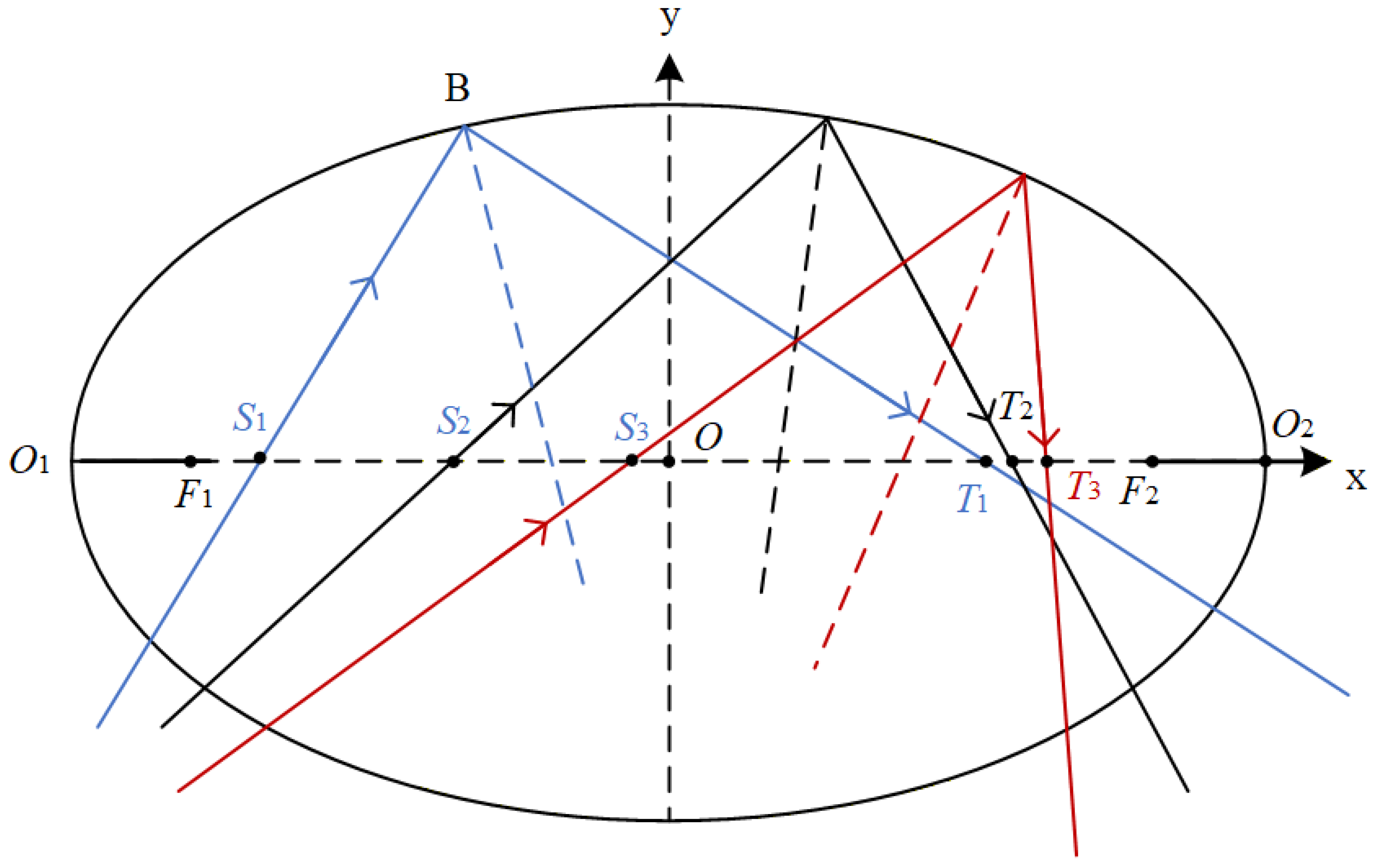
Under the conditions , , and , the signs and admissible ranges of the numerator and denominator can be further analysed. This analysis shows that . This result indicates that when the incident ray originates between the two foci, the reflected ray also intersects the major axis between the two foci. This property provides the theoretical basis for using ellipsoidal vanes to constrain out-of-field stray light in reflective baffle design.
According to this geometric relationship, a ray incident on the ellipsoidal vane from the region between the two foci will also emerge through this region after reflection. This process is illustrated in Figure 1. The property provides a geometric constraint for modelling and analysing stray light propagation within the baffle. Once the incident angle, field-of-view boundary, and structural dimensions are specified, ray tracing can predict the reflection direction of stray light on the vane surface. The stray radiation can therefore be guided away from the effective optical path of the detector. It can also be redirected toward the exterior of the baffle or into subsequent light-trapping regions.
Figure 1.
Reflection Characteristics of Rays Incident between the Foci of an Ellipsoidal Surface.
2.2. Geometric Constraints and Ray-Tracing Modelling of Out-of-Field Stray Radiation
Based on the ellipsoidal reflection property described above, this study uses multiple reflective ellipsoidal vanes to construct the stray light regulation structure inside the baffle. Unlike conventional absorptive vanes, which mainly rely on high absorptance coatings to attenuate stray radiation, the proposed reflective ellipsoidal vanes are designed to first change the propagation direction of stray light through their geometric surface profile. They then achieve energy attenuation in combination with locally absorptive surfaces. Specifically, the first vane at the entrance aperture is designed as a vertical vane. The remaining vanes adopt reflective ellipsoidal configurations. Because the entire baffle is axisymmetric about the optical axis, the vertical vane is generated by rotating a straight-line segment about the optical axis. Each ellipsoidal vane is formed by rotating the corresponding elliptical arc segment. To simultaneously redirect external stray light out of the system and suppress internal secondary scattering, different surface treatments are applied to different regions of each vane. The side facing the entrance aperture is coated with a highly reflective layer. The remaining regions are treated with a high-absorptance coating.
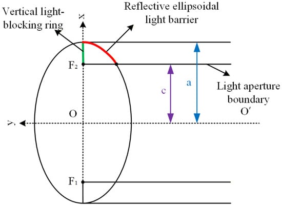
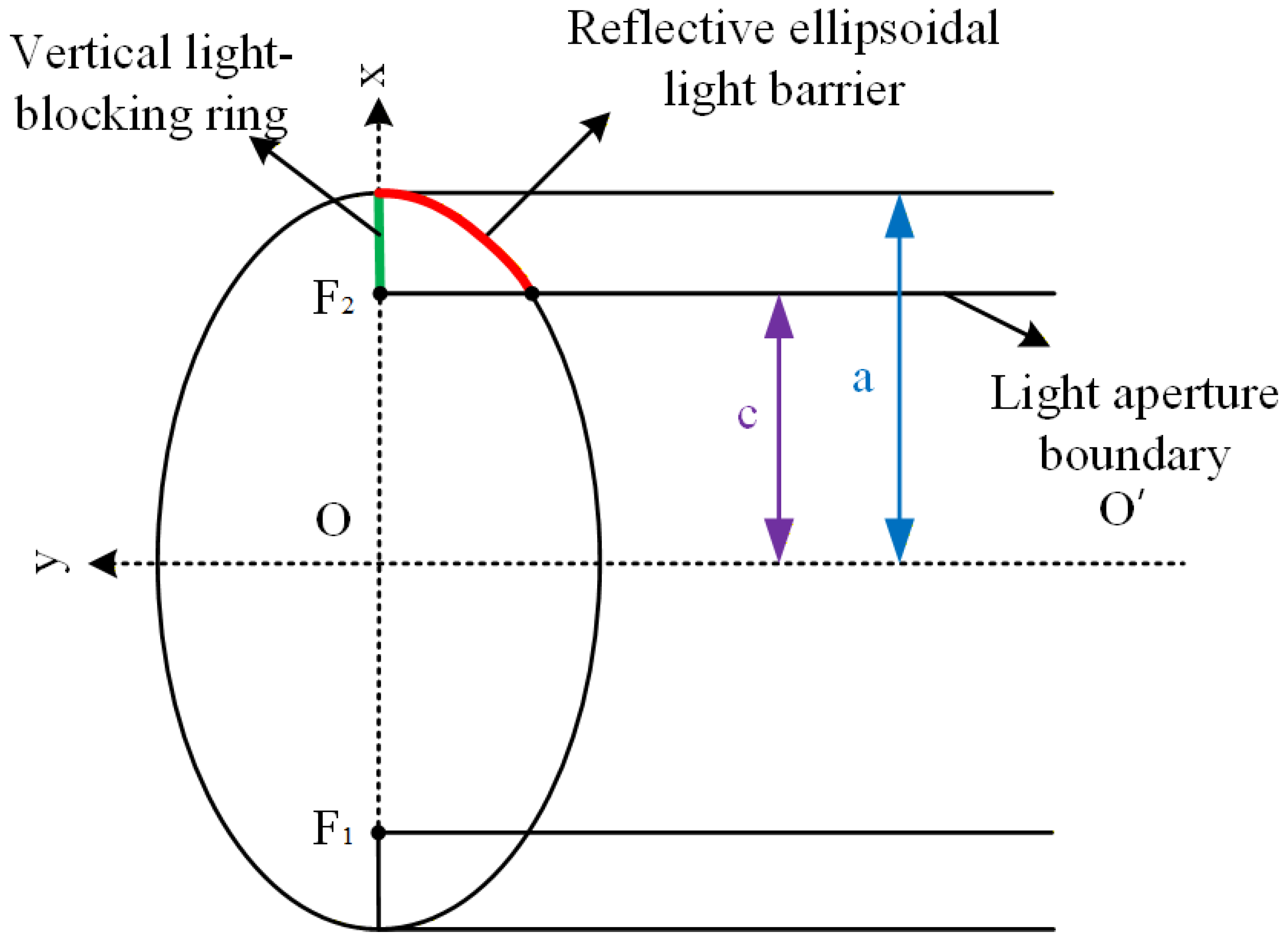
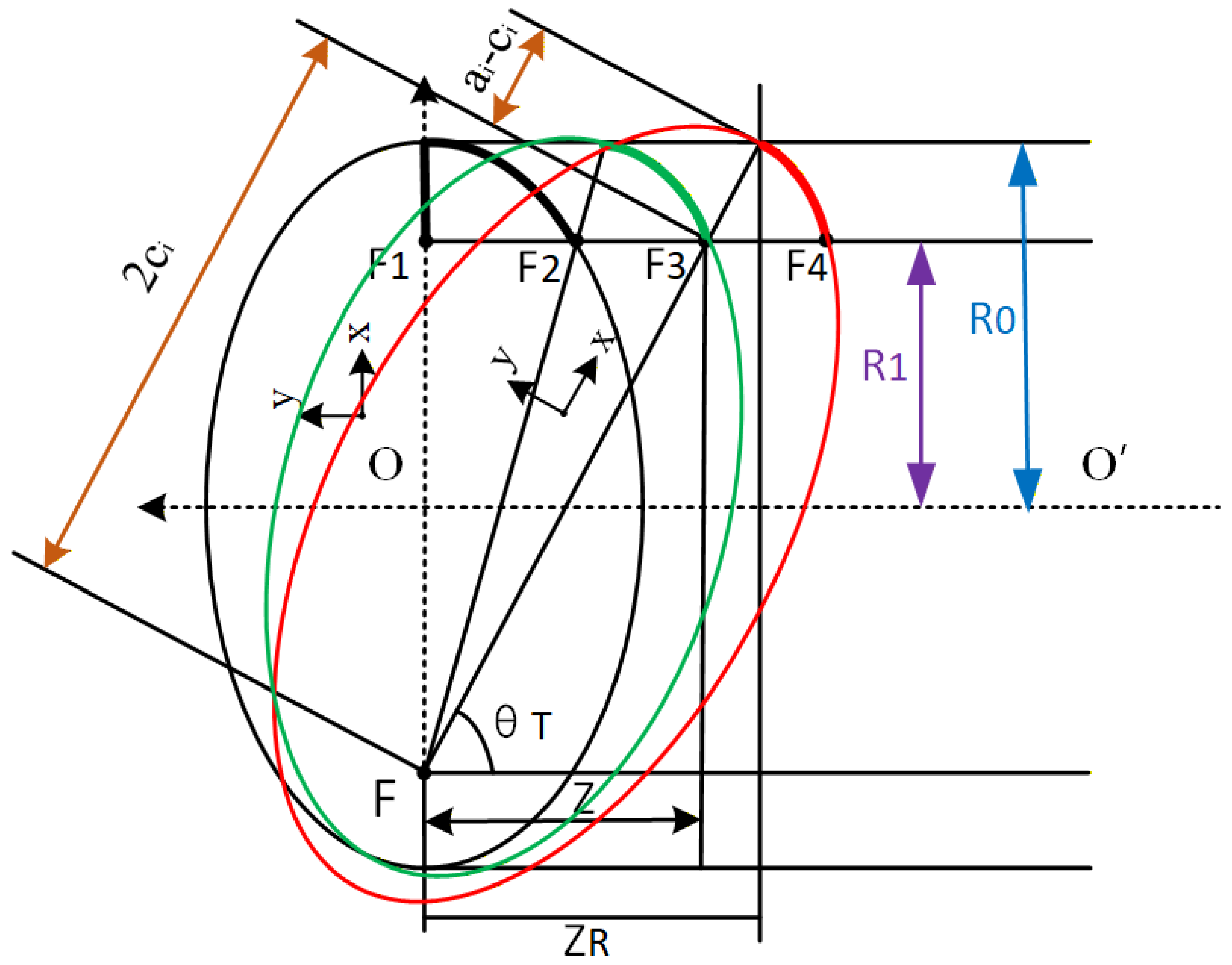
The geometric profiles and positioning relationships of the first vertical vane at the baffle entrance and the second to N-th ellipsoidal vanes are shown in Figure 2 and Figure 3. First, the generatrix position of the first vertical vane is determined according to the baffle length, outer diameter, exit aperture size, and system field-of-view angle. The generatrix is then rotated about the optical axis. A finite thickness is assigned to form the initial shielding boundary at the entrance aperture. This boundary defines the spatial starting position for the subsequent vanes. It also provides the first geometric constraint surface for the ray-tracing model. Based on the two endpoints of the first vane generatrix, the generatrix parameters of the first reflective ellipsoidal vane can be further determined. These parameters include the semi-major axis a and the focal distance c. Accordingly, the length of the first vertical vane can be expressed as , as shown in Figure 2.
Figure 2.
Geometric relationship between the vertical stop and the first ellipsoidal stop.
Figure 3.
Positioning principle of the cylindrical ellipsoidal baffle vane.
The first vertical vane determines the generatrix equation of the first reflective ellipsoidal vane, which can be expressed as
By combining this equation with the aperture boundary, the position, profile, and two foci, and , of the first reflective ellipsoidal vane can be determined. In this way, the structural dimensional constraints are converted into elliptical generatrix parameters. These parameters can be directly used in computational simulation. Consequently, the subsequent ray-tracing analysis in TracePro can evaluate stray light propagation paths based on the established geometric model.
For the second through the N-th reflective ellipsoidal vanes, the foci of the generatrix are jointly determined by the preceding vane boundary and the system field-of-view boundary. Each subsequent vane is therefore not designed independently. Instead, it further constrains the out-of-field rays that may enter the system based on the shielding boundary established by the preceding vane. The position and profile of each subsequent vane can be determined as follows:
Thus, the stray light suppression angle determines the critical out-of-field ray boundary, and this boundary further constrains the focal positions and generatrix parameters of the subsequent ellipsoidal vanes. In this way, a quantitative mapping relationship is established among the suppression angle, vane position, and ellipsoidal generatrix parameters. The coordinate system is defined as shown in Figure 2. In this system, the y axis corresponds to the optical axis of the optical and mechanical system. The x axis coincides with the straight line on which the first vertical vane is located. This coordinate system allows the axial positions, radial heights, and field-of-view boundaries of all vanes to be described within a unified geometric framework. It also facilitates subsequent parametric modelling and ray-tracing computation.
In the above formulation, denotes the distance from the optical axis to the inner wall of the reflective ellipsoidal baffle. It corresponds to the semi-major axis a shown in Figure 3. Similarly, denotes the distance from the optical axis to the aperture boundary of the reflective ellipsoidal baffle. It corresponds to the focal distance c shown in Figure 3. Thus, and characterise the outer structural boundary and the effective clear aperture boundary of the baffle, respectively. They also serve as key parameters linking structural design with stray light suppression performance.
Once the baffle length, entrance aperture diameter, exit aperture diameter, and half field-of-view angle are specified, the position, profile, and number of the second through the N-th ellipsoidal vane generatrices can be progressively determined using the above geometric constraints. This parametric design strategy transforms the baffle from an empirically defined shielding structure into a computable, simulatable, and optimisable front-end light-field regulation component.
2.3. Light Trap Configuration and Propagation Suppression of Residual Stray Radiation
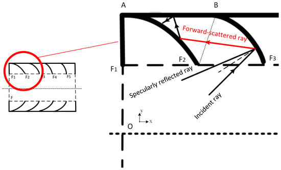
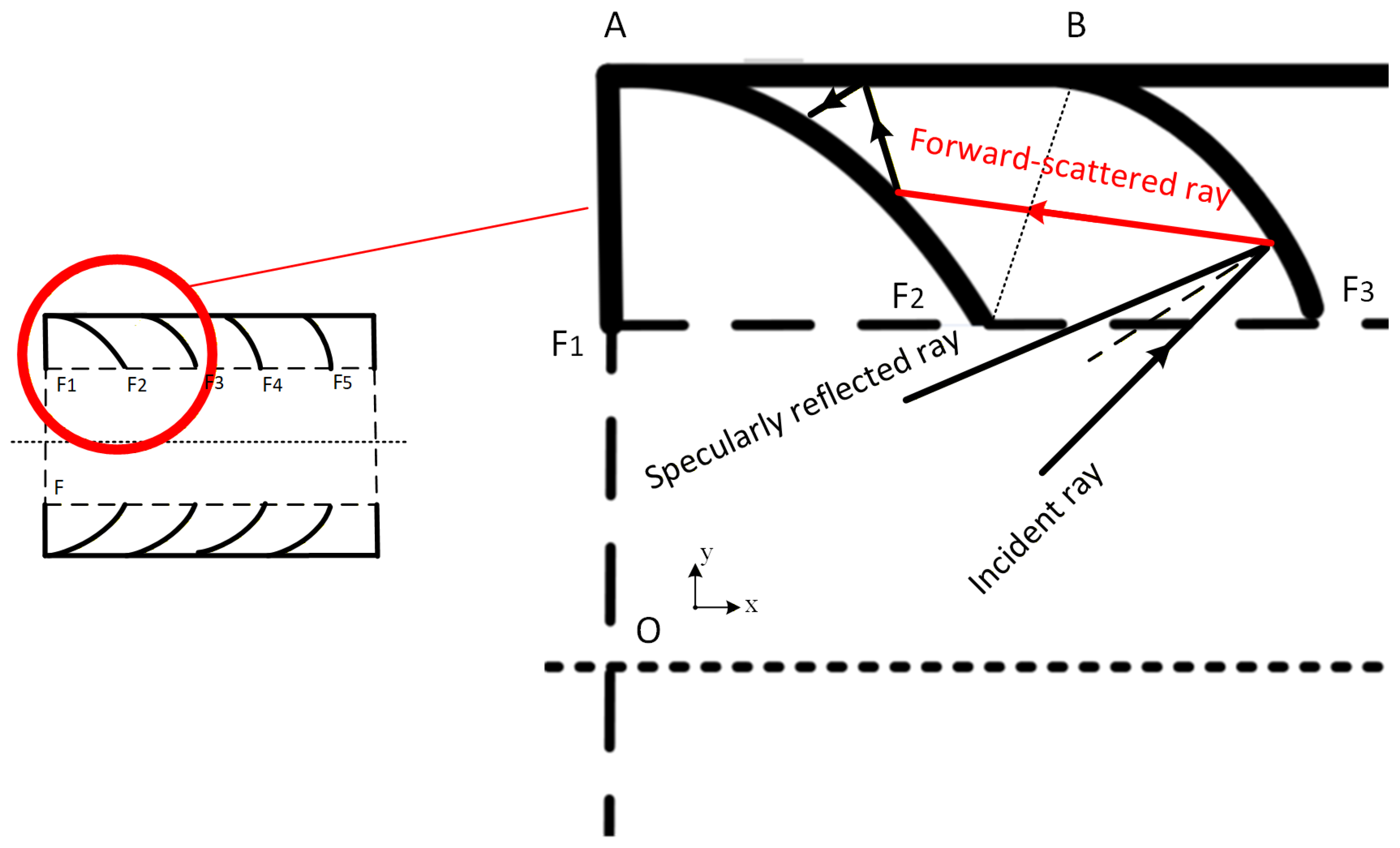
During stray light propagation inside the baffle, not all rays are redirected out of the baffle after a single reflection. Due to surface roughness, edge morphology, and variations in incident angle, some rays may scatter and enter the local regions between adjacent vanes. In this study, these regions are regarded as light traps between the ellipsoidal vanes, as illustrated in Figure 4. The function of the light trap structure is to reduce the probability that residual stray light continues to propagate toward the imaging channel. This is achieved through multiple reflections, occlusion, and absorption.
Figure 4.
Light-trapping mechanism between adjacent ellipsoidal vanes.
Assume that the scattered ray forms an angle with the vane. The admissible range of is determined by the relative positions of two adjacent vanes. To describe its propagation path, the scattered ray is expressed in the local coordinate system of the corresponding vane as a straight line, . By combining this line with the elliptical generatrix described by Equation (8), we obtain
which can be rewritten as
Accordingly, the intersection between the scattered ray and the preceding vane can be determined. This intersection is denoted as point P. The other root, which does not satisfy the physical propagation path, is discarded. The coordinate of P is given by , where . At point P, the normal line of the preceding vane can be expressed as
After the scattered ray reaches the preceding vane, its reflected path satisfies specular reflection symmetry with respect to the local normal at P. According to the geometric relationship between the incident ray slope and the normal slope, the slope of the reflected ray can be calculated as
Therefore, the reflected ray can be written as
The above derivation shows that the light trap region formed between adjacent ellipsoidal vanes can be quantitatively described using geometric relations. Even when residual stray light entering the light trap undergoes forward scattering, it can still be redirected toward non-aperture regions. This redirection is achieved under the combined constraints of the curved vane surface and the shielding boundaries. As a result, the probability that residual stray light reaches the detector plane is reduced. This theoretical analysis provides a path-level basis for subsequent refined stray light simulation using realistic three-dimensional vane edge models.
3. Realistic Three-Dimensional Vane Edge Modelling for Predicting Infrared Imaging Degradation
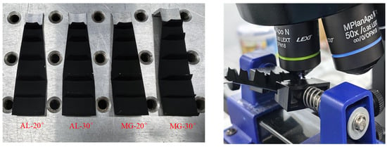
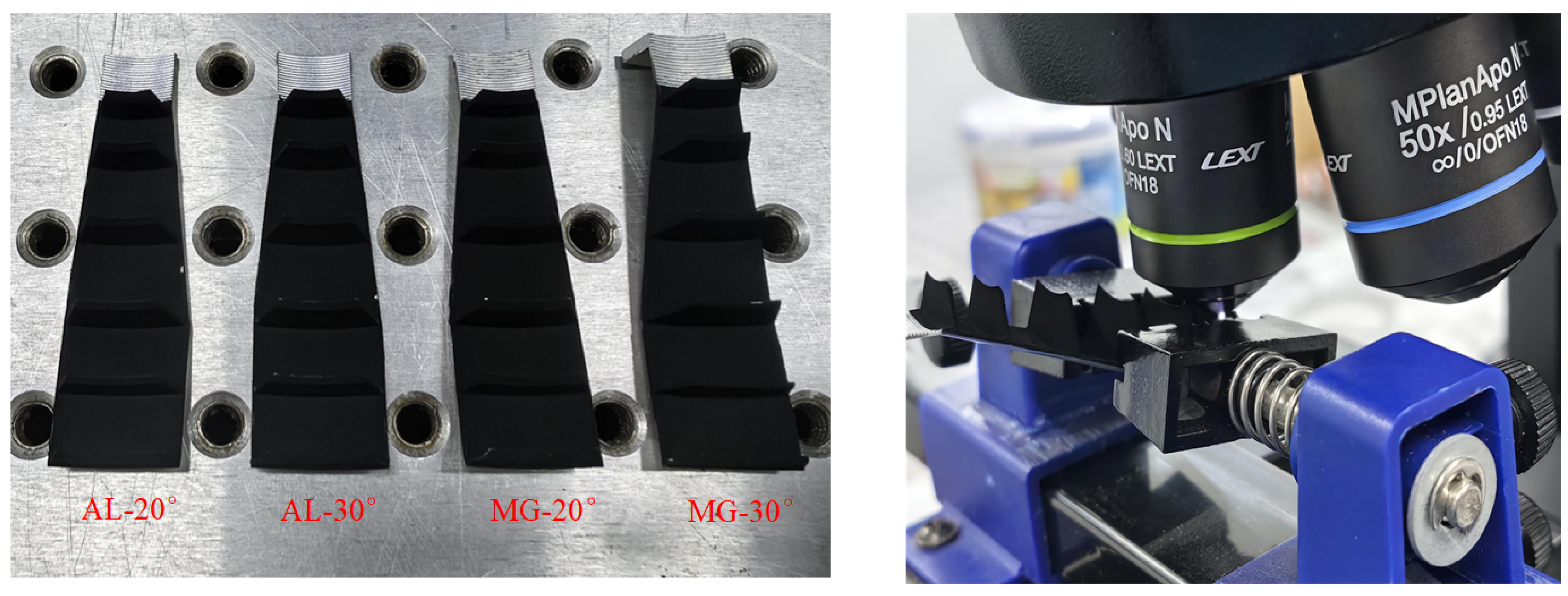
In the reflective ellipsoidal baffle, the vane edge is located in the transition region between the clear aperture boundary and the shielding structure. It is a critical surface that affects the scattering direction, energy distribution, and secondary propagation paths of stray light. In conventional simulations, the edge is often approximated as an ideal circular arc or a regular trapezoidal profile. Although these simplified models are convenient for geometric construction, they cannot capture edge blunting, local undulations, or microscale roughness introduced during fabrication. This limitation may lead to discrepancies between the computed point source transmittance (PST) and the actual stray light suppression performance [21,25,26,27]. To improve the fidelity of the computational baffle model, this study incorporates realistic three-dimensional edge morphology into the forward analysis of stray light propagation. Specifically, a laser confocal microscope (OLS5100-SAF) is used to scan and reconstruct vane edges fabricated from different materials and with different machining angles. This process yields four categories of edge topography data, namely , , , and , as shown in Figure 5. This treatment extends the baffle design methodology beyond idealised geometric configuration analysis. It enables computational stray light analysis based on realistic manufactured surfaces.
Figure 5.
Laser scanning microscopic measurement of the baffle vane edge.
After the three-dimensional vane edge morphology is acquired, the microscopic measurement data must be geometrically preprocessed, corrected in coordinate space, and reconstructed as a model. Only after these steps can the data be used as input surfaces for ray-tracing simulation. This process converts the microtopographic information of the manufactured surface into computable optical boundary conditions. It enables the simulation model to incorporate both the macroscopic structural constraints of the baffle and the microscopic scattering characteristics of the vane edge. As a result, the simulated stray light propagation process becomes more consistent with that in an actual imaging system.
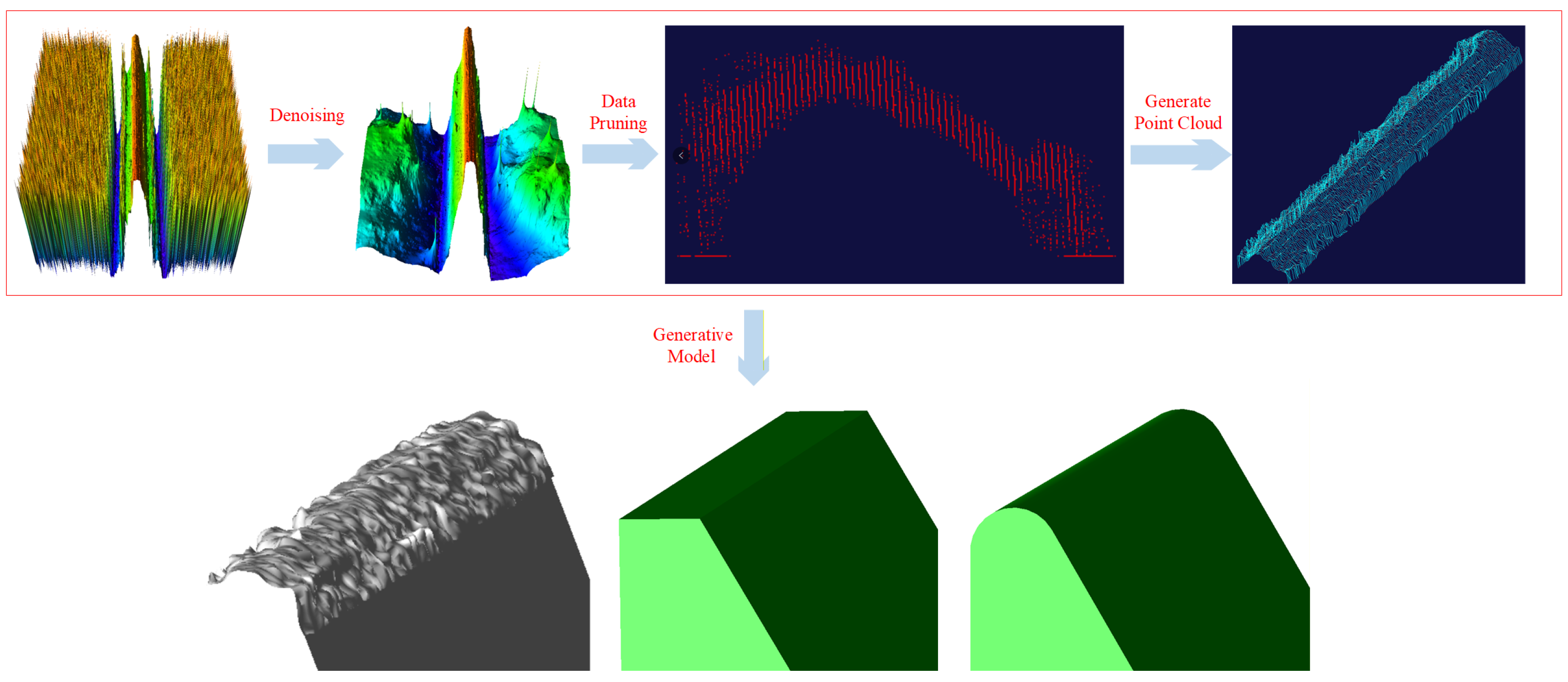
Realistic surface model: First, the point-cloud data acquired by the laser confocal microscope are denoised, corrected for tilt, and spatially registered. These steps reduce the influence of measurement posture deviations and local outliers on geometric reconstruction. Subsequently, two rounds of region trimming are performed. This procedure retains only the effective data associated with edge scattering. Multiple cross sections are then uniformly sampled along the edge direction. The sectional profiles are sorted and converted into continuous curves. Finally, these sectional curves are used to construct a realistic three-dimensional vane edge surface model. Compared with idealised models, this model preserves morphological features such as edge width, edge rounding, local protrusions, local depressions, and machining textures. Therefore, it can serve as a refined computational surface for subsequent stray light simulation.
After the realistic three-dimensional surface model is established, point-cloud samples are further extracted from the surface. These samples are used to construct a fitted trapezoidal model and a fitted circular arc model for comparison. The three models represent different levels of geometric approximation. The realistic surface model reflects the measured morphology. The fitted circular arc model preserves the dominant contour associated with edge blunting. The fitted trapezoidal model represents a simplified regular boundary commonly used in engineering modelling. By comparing the PST differences among the three models under identical incident conditions, the influence of refined edge modelling on computational optical simulation results can be evaluated.
Trapezoidal approximation model: The distribution of edge widths in the uniformly sampled cross sections is statistically analysed. The mean value is then adopted as the edge width of the trapezoidal model. This model requires only a limited number of parameters and is straightforward to construct. Therefore, it is suitable for rapid simulation. However, its straight boundaries cannot accurately describe the curvature variation or local microstructures of the real vane edge. Therefore, the trapezoidal approximation model is more appropriate as a comparative baseline. It represents a coarse geometric model for evaluating the influence of edge morphology on stray light simulation.
Circular arc approximation model: Several representative vane edge cross sections are selected, and each sectional profile is fitted using a circular arc. The average fitted radius is then used as the geometric parameter of the circular arc model. Compared with the trapezoidal model, the circular arc model better characterises edge blunting and rounded transitions. However, it still neglects three-dimensional undulations along the edge direction and nonuniform machining traces. The fitting procedure for the circular arc is described as follows.
The general equation of the fitted circular arc for the vane edge can be expressed as
where x and y denote the horizontal and vertical coordinates of the fitted data points, respectively. The coefficients and are linear terms related to the centre position of the circle. The coefficient is a constant term associated with the arc radius.
In practical measurements, the observed points do not strictly lie on an ideal circular arc. This deviation is caused by machining errors, surface microtopography, and measurement noise. Therefore, a residual term should be introduced when constructing the circular arc generatrix model. The residual vector can be written as
where denotes the residual between the ith observed point and the fitted circular arc generatrix. The variables and are the horizontal and vertical coordinates of the ith observed point, respectively. The parameter n denotes the number of observed points used for fitting.
According to the least squares criterion, the optimal estimates of the fitting parameters can be obtained from the normal equation:
The centre coordinates and radius of the fitted circle can then be calculated as
where denotes the centre of the fitted circular arc, and r represents the fitted arc radius. In this way, the microscopically measured cross sectional profile of the vane edge can be converted into a circular arc approximation model. This model is convenient for subsequent ray-tracing implementation [27].
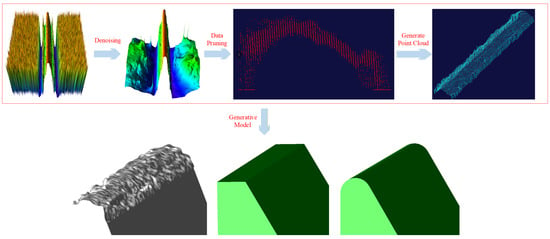
As shown in Figure 6, three types of vane edge models are constructed in this study: the fitted surface model, the fitted trapezoidal model, and the fitted circular arc model. This modelling procedure converts microscopic measurement data into simulation models with explicit geometric boundaries and computable parameters. It therefore provides a basis for analysing how vane edge modelling accuracy affects the prediction of stray light scattering.
Figure 6.
Construction workflow of the refined vane edge model.
Because the fitted surface is reconstructed directly from the three-dimensional point cloud acquired by the laser confocal microscope, its geometric error mainly originates from measurement accuracy and data preprocessing. Given the high resolution of the microscope and the good repeatability of the measurements, the fitted surface is regarded in this study as the computational model that most closely approximates the actual vane edge morphology. In contrast, the fitted circular arc and trapezoidal models are low-dimensional geometric approximations. They preserve only partial characteristics of the vane edge. Therefore, if the PST results obtained from the three models show noticeable differences, this indicates that vane edge microtopography has a substantial influence on stray light scattering behaviour. It also suggests that an overly simplified edge model may reduce the reliability of baffle simulation results.
For each group of vane edge samples, the three models described above are established. Edge scattering ray-tracing simulations are then performed under identical incident conditions and surface properties. The stray light incidence angle is varied from to at an interval of . This setting yields ten off-axis incident angle conditions in total. The surface property is defined as Q17, whose measured absorptance at is 0.979136. In the simulations, point source transmittance (PST) is used as the evaluation metric. It characterises the stray light suppression capability of different vane edges under varying material types, machining angles, and geometric modelling strategies.
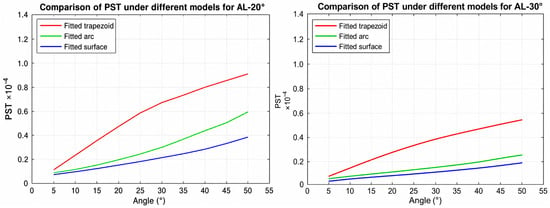
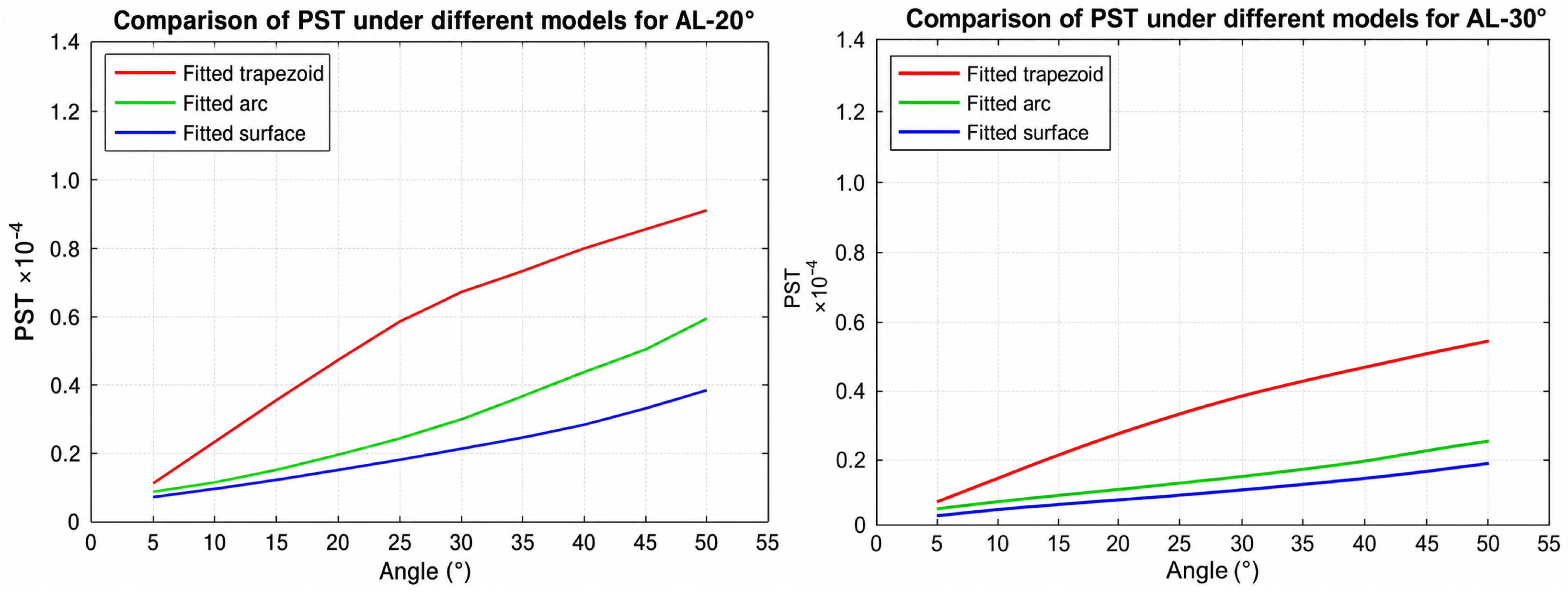
Figure 7 presents the PST curves of aluminium-alloy vanes under different edge-machining angles and fitting models. For both the and machining conditions, the three models show a generally consistent trend. The fitted surface model yields the lowest PST, followed by the fitted circular arc model. In contrast, the fitted trapezoidal model produces the highest PST. This result should not be interpreted as indicating that a lower PST alone proves higher prediction accuracy. Instead, it shows that different levels of edge-geometry approximation can lead to different stray light predictions under identical surface-property settings. The realistic surface model is reconstructed from measured three-dimensional point-cloud data and therefore provides a higher-fidelity geometric representation of the manufactured vane edge. In contrast, the trapezoidal model represents a simplified engineering approximation and may serve as a conservative upper-bound reference for residual stray light estimation. Among the tested conditions, the PST curve corresponding to is the lowest. This indicates that this vane edge configuration produces the smallest amount of first-order scattered stray radiation entering the system.
Figure 7.
Comparison of PST curves for aluminium-alloy vanes under different edge-machining angles and fitting models (left: AL-20°; right: AL-30°).
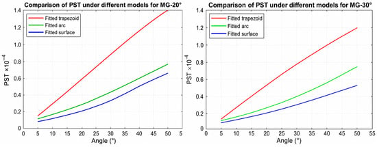
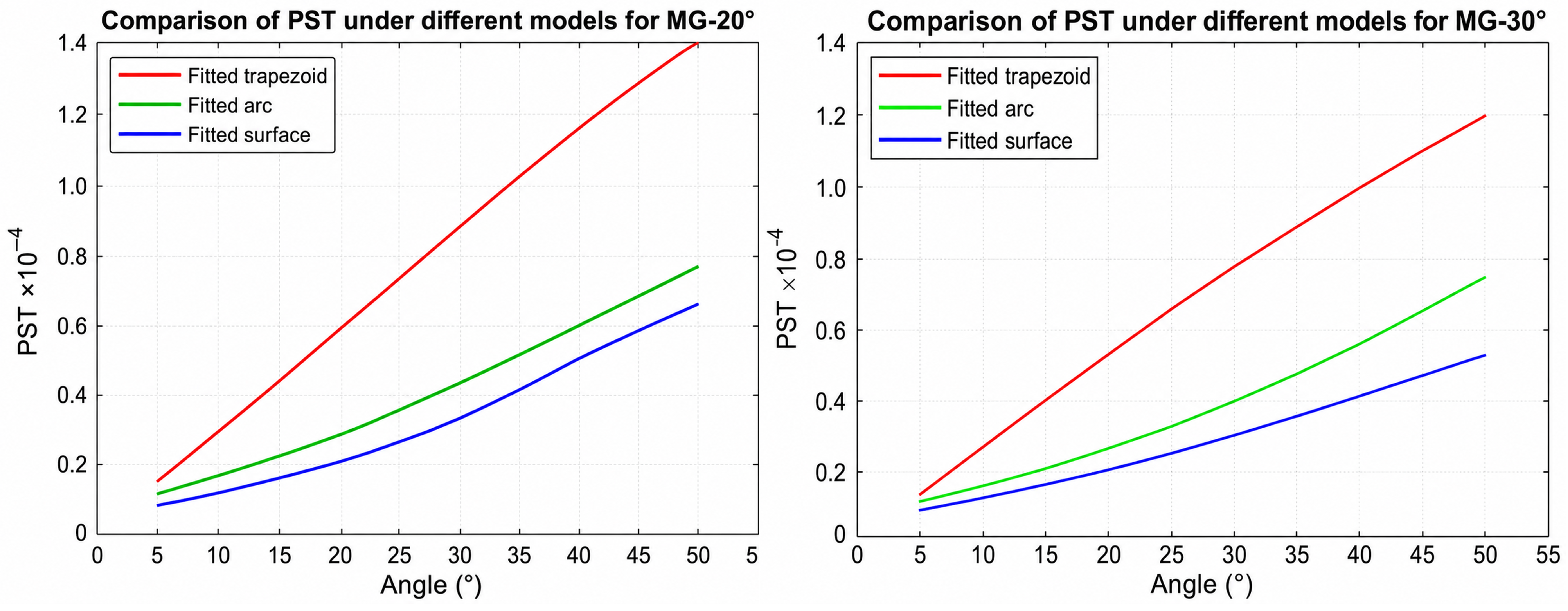
As shown in Figure 8, the magnesium-alloy vanes show a similar trend under different machining angles. The fitted surface model consistently achieves better stray light suppression performance than both the circular arc model and the trapezoidal model. This result suggests that realistic edge morphology modelling is not limited to a specific material. Instead, it has broader significance for computational stray light simulation of critical baffle surfaces. In other words, incorporating microscopically reconstructed three-dimensional morphology into the ray-tracing model improves the consistency and physical fidelity of stray light prediction. This improvement is observed across different materials and fabrication processes.
Figure 8.
Comparisonof PST curves for magnesium-alloy vanes under different edge-machining angles and fitting models (left: MG-20°; right: MG-30°).
To further distinguish the effects of material type and machining angle on vane edge scattering characteristics, the fitted surface models corresponding to different materials and machining angles are extracted separately for comparative analysis.
The main-surface roughness of the vanes may also contribute to stray light scattering. A rougher surface generally increases diffuse scattering and reduces specular reflection, which may increase the probability of residual stray light reaching the detector. In the present study, the influence of surface condition is partly reflected in the measured spectral reflectance of the coated surfaces and in the reconstructed edge morphology. Therefore, the surface-property setting includes the combined influence of coating quality and local surface condition.
Regarding the difference between aluminium-alloy and magnesium-alloy samples, oxidation alone is not sufficient to fully explain the PST difference. Since the same Q17 surface model was used in the edge comparison, the difference should mainly be interpreted from the measured edge morphology, machining texture, local roughness, and possible oxide-layer effects. Magnesium alloy is more chemically active, and slight oxidation may change the local edge morphology and scattering behaviour before measurement. However, material-specific BSDF data and oxide-layer optical constants were not independently measured in this study. Therefore, oxidation is considered only as a possible factor influencing the measured edge morphology, rather than the sole or definitive reason for the higher PST.
The increasing difference among the realistic, circular-arc, and trapezoidal edge models with increasing off-axis angle is mainly caused by the higher sensitivity of large-angle stray rays to edge morphology. At larger off-axis angles, more rays interact with the vane edge under oblique or near-grazing incidence. Therefore, small differences in edge rounding, local protrusions, depressions, and three-dimensional undulations can cause larger changes in scattering direction and residual propagation path. This explains why the PST differences among the three edge models become more pronounced at larger off-axis angles.
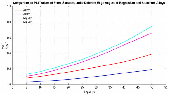
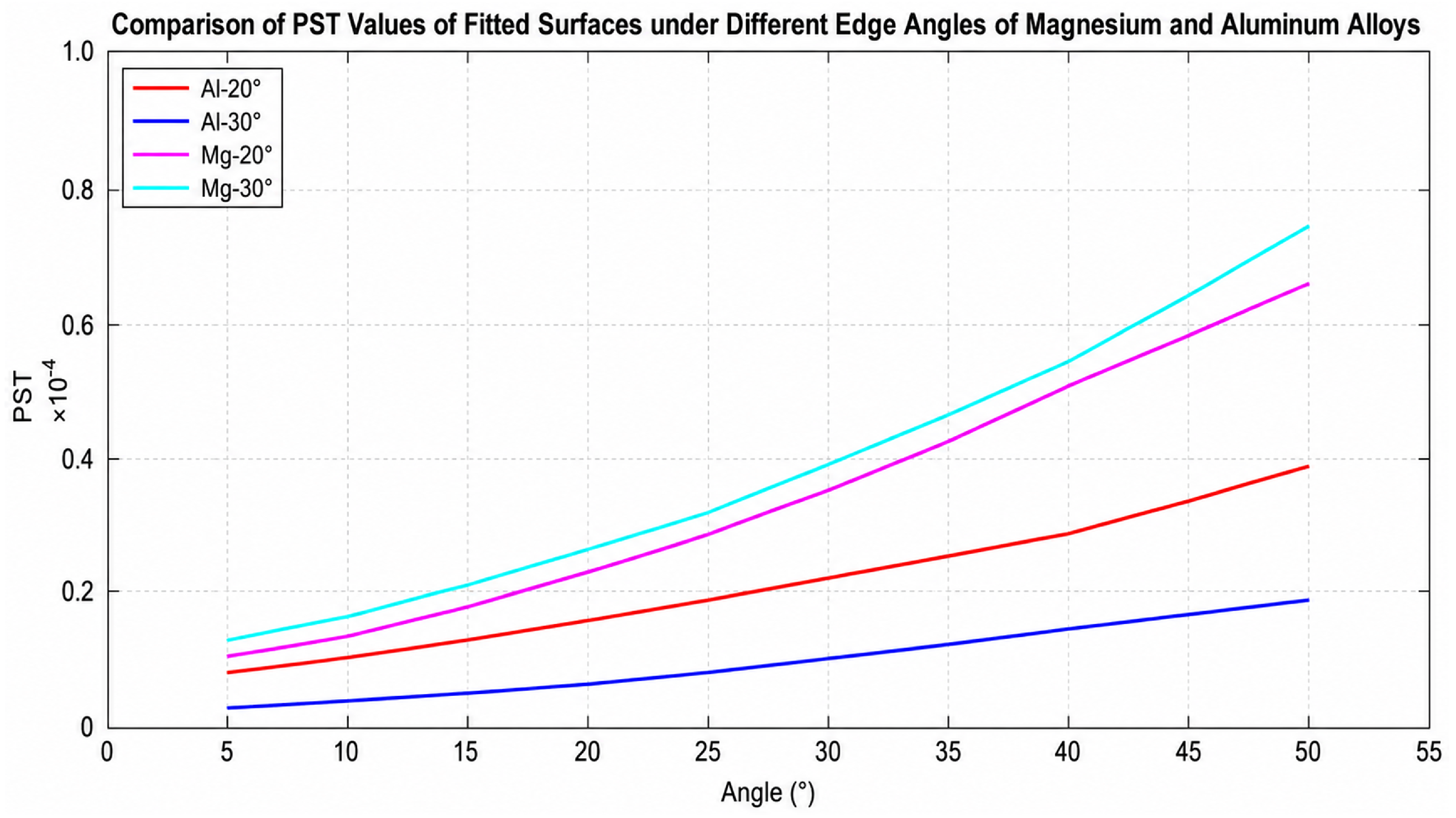
The results in Figure 9 indicate that the PST curves of AL-20° and AL-30° are generally lower than those of MG-20° and MG-30°. This suggests that, under the same edge-machining angle and identical Q17 surface-property setting, the measured aluminium-alloy edge morphology is more favourable for suppressing first-order stray light scattering than the magnesium-alloy edge morphology. Considering the results obtained at different incident angles, AL-30° yields the lowest overall PST level.
Figure 9.
Comparison of fitted-surface PST values for magnesium- and aluminium-alloy vane edges at different machining angles.
Given the mature machining process, favourable structural stability, and optimal simulation performance of the edge configuration, aluminium alloy is selected as the material for the subsequent split reflective ellipsoidal baffle. The edge-machining angle is designed to be approximately . This choice reflects a balanced consideration of computational simulation results and practical manufacturability.
4. Computationally Constrained Structural Optimisation of the Split Baffle
Based on the three-dimensional edge reconstruction and first-order scattering simulation results presented in Section 3, aluminium alloy is selected as the primary substrate material for the overall baffle design. The vane edge-machining angle is set to approximately . This design choice is not based solely on empirical material selection. Instead, it is jointly determined by realistic edge morphology modelling, PST-based computational evaluation, and engineering fabrication constraints. Accordingly, the baffle design workflow establishes a computational closed loop from microscopic surface modelling to macroscopic structural optimisation.
4.1. Construction of the Computational Simulation Model
According to the operational requirements of the infrared camera for internal environmental monitoring in a radio telescope, the principal baffle parameters are first determined. These parameters include the overall dimensions and main optical constraints, as listed in Table 1. The structural outer diameter, baffle length, stray light suppression angle, half field-of-view angle, and exit aperture diameter jointly define the range of out-of-field rays that may enter the system. They also determine the boundary conditions for solving the subsequent vane positions and elliptical generatrix parameters. While satisfying the clear aperture requirements, selected parameters are assigned appropriate design margins. These margins accommodate subsequent prototype fabrication, assembly, and surface treatment processes.
Table 1.
Dimensional parameters of the proposed baffle.
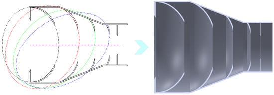
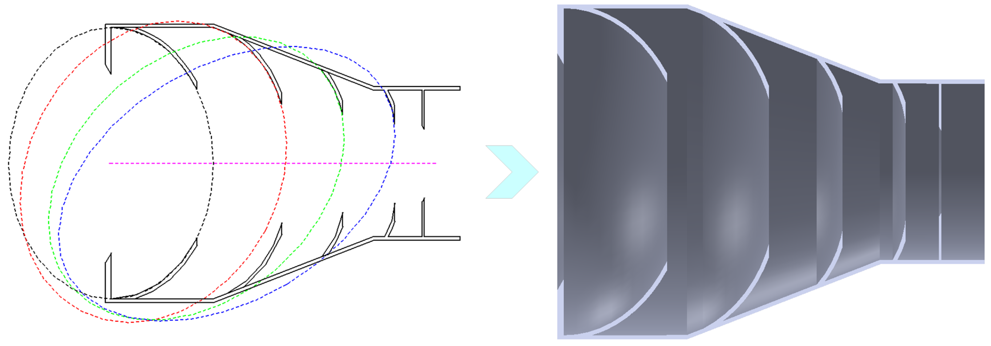
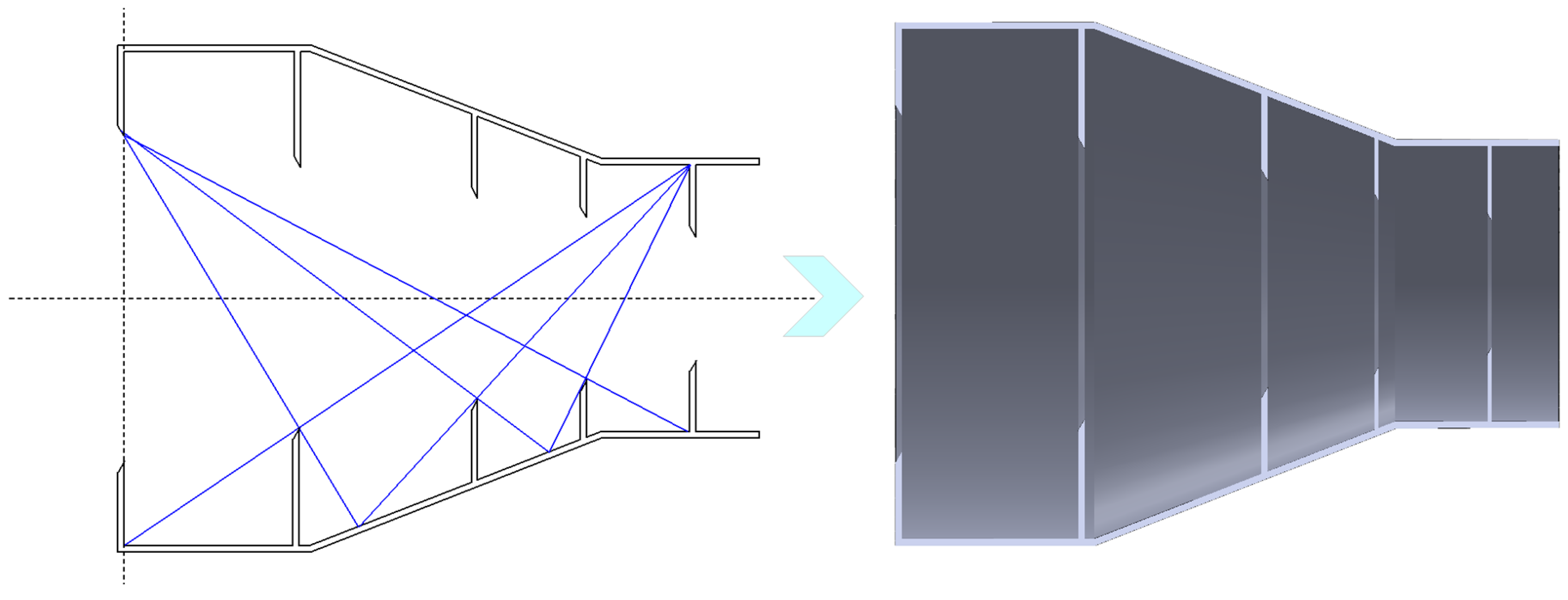
According to the design principle of the reflective ellipsoidal baffle established in Section 2, each ellipsoidal vane is generated by rotating an elliptical generatrix about the optical axis. Table 2 lists the key parameters of the generatrix equation for each ellipsoidal vane. These parameters include the semi-major axis, semi-minor axis, focal distance, and rotation angle. Based on these parameters, the two-dimensional cross-sectional profile of the reflective ellipsoidal vanes can be constructed. The corresponding three-dimensional geometric model can then be generated, as shown in Figure 10. This model serves not only as a structural representation of the baffle but also as the geometric input for subsequent Monte Carlo ray-tracing simulations. It enables the reflection, scattering, and residual propagation of stray light inside the baffle to be quantitatively analysed.
Table 2.
Parameters of the elliptical generatrices for the ellipsoidal baffle vanes.
Figure 10.
Geometric model of the reflective ellipsoidal baffle.
The ellipsoidal generatrix parameters were not determined by empirical adjustment alone. They were first constrained by the system-level requirements, including the baffle length, outer diameter, exit aperture, half field-of-view angle, and stray light suppression angle. Based on these boundary conditions, the critical out-of-field ray boundary and the shielding boundary of the preceding vane were used to determine the initial focal positions and generatrix parameters. Parameter scanning was then performed within the manufacturable range to select the parameter combination with lower PST and feasible mechanical implementation. Therefore, the final semi-major axis, semi-minor axis, focal distance, and rotation angle of each vane were determined by combining geometric constraints, PST-based simulation feedback, and manufacturability requirements.
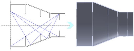
To evaluate the advantages of the reflective ellipsoidal configuration over conventional designs, an absorptive baffle model is also established, as shown in Figure 11. The two baffle models are compared under identical overall dimensions, incident angle ranges, and evaluation metrics. This setting minimises the influence of non-structural factors on the simulation results. In this way, the observed differences in PST mainly reflect the effects of the stray light suppression mechanism and surface properties.
Figure 11.
Geometric model of the absorptive baffle.
4.2. Computational Optical Simulation for Baffle Performance Evaluation
Point source transmittance (PST) is used to characterise the relative proportion of stray light reaching the detector plane at different off-axis angles. It essentially represents the residual irradiance contribution of an out-of-field source to the imaging plane. For a given off-axis angle , PST can be expressed as
where denotes the incident stray light flux, represents the residual stray light flux reaching the detector plane, and is the stray light irradiance distribution on the detector plane. Therefore, a reduction in PST indicates stronger optical suppression capability of the baffle. It also implies that infrared image degradation phenomena can be effectively alleviated. These phenomena include background elevation, local bright spots, and contrast reduction [8,9,19,20,22,28].
After the geometric model, surface properties, and source conditions are configured in TracePro, Monte Carlo ray-tracing simulations are performed for both the absorptive baffle and the reflective ellipsoidal baffle. The off-axis incident angle of stray light is varied from to .
The surface treatments of the two baffles were configured differently. For the conventional absorptive baffle, the inner wall and all vane surfaces were assigned the Q17 high-absorptance coating. For the proposed reflective ellipsoidal baffle, the front surfaces of the ellipsoidal vanes facing the entrance aperture were defined as reflective surfaces, whereas the rear surfaces of the vanes, the baffle inner wall, and other non-functional regions were assigned the Q17 high-absorptance coating. Therefore, the proposed baffle does not rely on global absorption. Instead, it first redirects out-of-field stray light through the reflective ellipsoidal surfaces and then attenuates residual scattered light through locally absorptive regions.
For the reflective front surfaces of the vanes, an aluminium reflective film was used. The coating was provided by an external coating vendor, and the detailed deposition process was not disclosed to the authors. The measured average spectral reflectance in the working infrared band was 94.7%. For the rear surfaces of the vanes and the inner wall, the Q17 high-absorptance coating was prepared by spraying, with a coating thickness of approximately 50 µm. The measured average spectral absorptance in the working infrared band was 97.91%, which is consistent with the nominal value.
The split structure allows each vane to be processed and coated separately. Therefore, the spraying or coating distance and angle can be adjusted for each small curved surface, which is more favourable than treating an integrated deep-cavity structure. Due to the limitation of the available measurement equipment, a quantitative coating-uniformity test was not performed in this study.
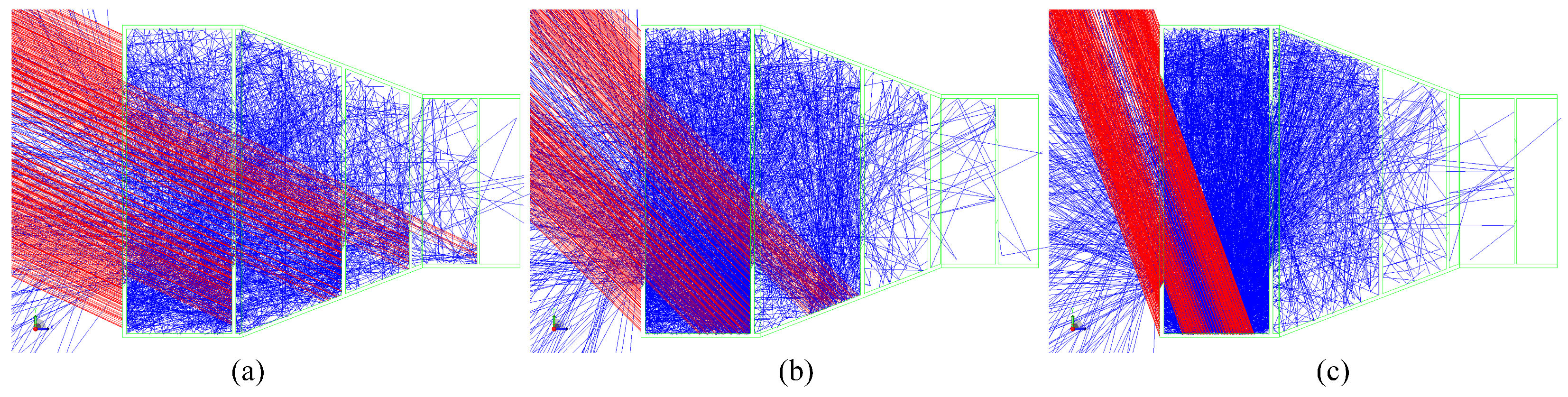
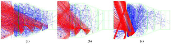
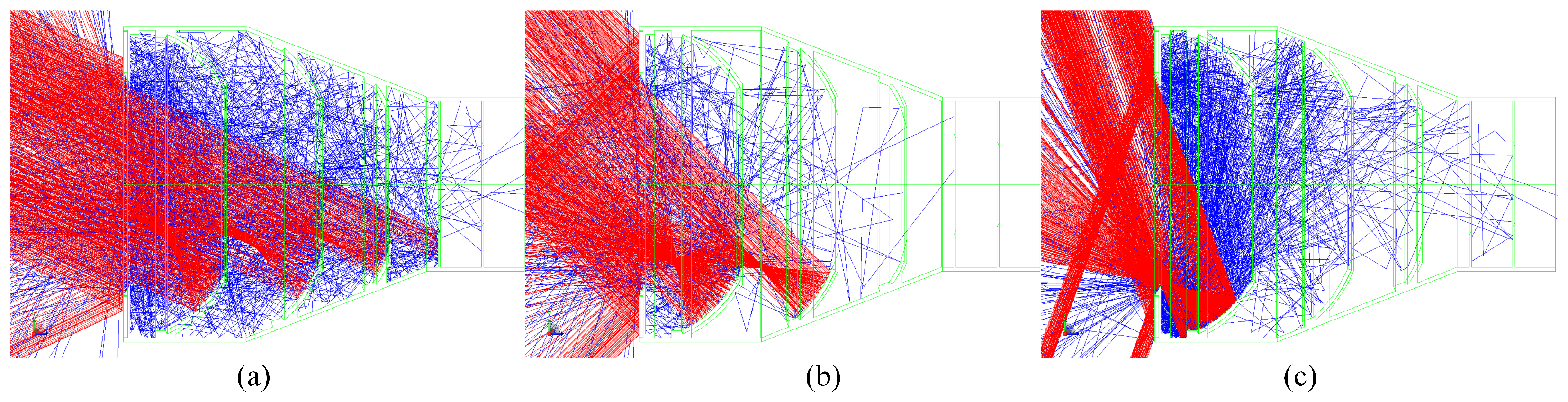
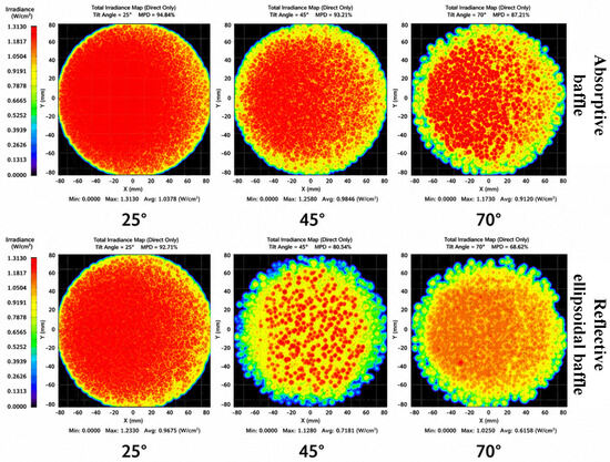
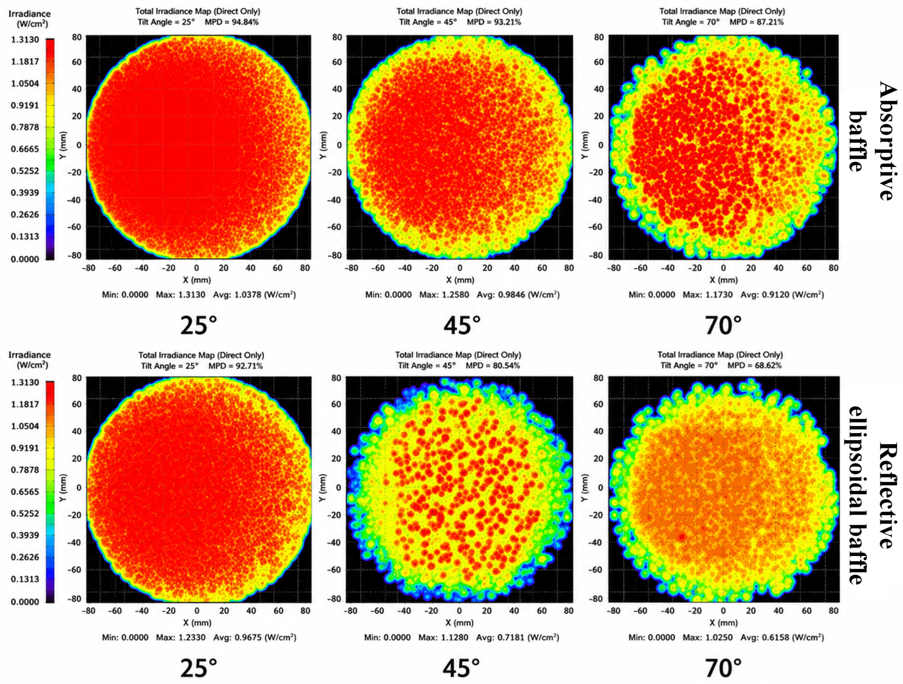
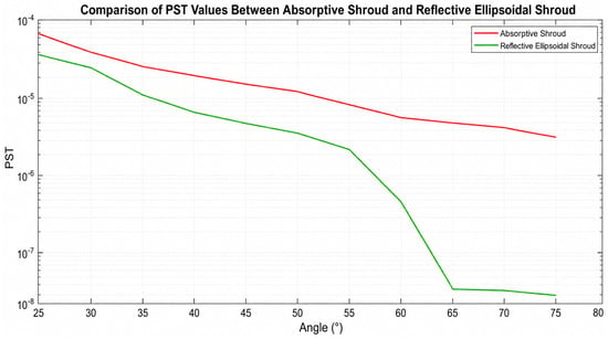
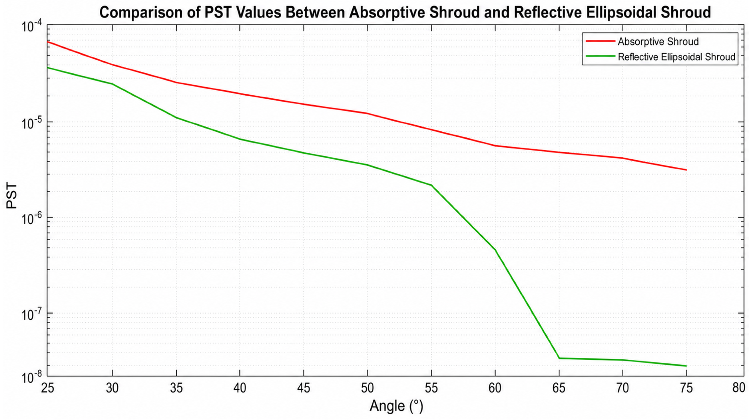
Figure 12 and Figure 13 show the stray light propagation paths inside the absorptive baffle and the reflective ellipsoidal baffle, respectively. Figure 14 presents the detector plane irradiance distributions at selected incident angles. Figure 15 shows the corresponding PST curves. Through the joint analysis of propagation paths, irradiance distributions, and PST curves, the baffle capability to suppress out-of-field stray light can be evaluated. This evaluation is conducted from the perspective of the forward model of imaging degradation.
Figure 12.
Propagation paths of stray light inside the absorptive baffle: (a) incidence; (b) incidence; (c) incidence.
Figure 13.
Propagation paths of stray light inside the reflective ellipsoidal baffle: (a) incidence; (b) incidence; (c) incidence.
Figure 14.
Comparison of detector-plane irradiance distributions of the two baffles at selected off-axis angles.
Figure 15.
Comparisonof the PST curves of the two baffles.
As shown in Figure 15, the PST of the reflective ellipsoidal baffle remains lower than that of the absorptive baffle over the off-axis incidence range of to . This indicates that the proposed baffle more effectively reduces the probability of out-of-field stray light entering the imaging channel. In particular, when stray light is incident at an off-axis angle of , the reflective ellipsoidal baffle improves stray light suppression by approximately one order of magnitude compared with the absorptive baffle. When the off-axis angle exceeds , this advantage further increases to nearly two orders of magnitude. These results demonstrate that the ellipsoidal vanes do not rely only on absorption to attenuate stray light energy. Instead, they redirect part of the stray radiation toward the exterior of the baffle or into the light trap regions through geometric reflection. This reduces the irradiance contribution of stray light at the detector plane. This characteristic is particularly important for infrared cameras. Reducing the absorbed thermal load inside the baffle helps mitigate the risk of internal stray radiation caused by structural self-heating.
4.3. Manufacturing-Constrained Optimisation of the Split Baffle Model
The ideal reflective ellipsoidal model verifies the stray light suppression advantage of this configuration through computational simulation. However, practical engineering implementation is further constrained by surface figure accuracy, coating accessibility, uniformity of internal blackening treatment, and assembly error. Therefore, based on the ideal optical model, this study further performs manufacturing-oriented structural optimisation. The computational model is transformed into a split configuration that is manufacturable, assemblable, and experimentally testable. The objective of this process is to improve the machining quality of critical optical surfaces and the controllability of surface treatment. At the same time, the effectiveness of the ellipsoidal reflection paths and the light trap structure should be preserved as much as possible [29,30,31].
For the absorptive baffle, the structural configuration is relatively simple. Existing machining processes can generally meet the requirements for dimensional accuracy and internal blackening treatment. However, if the reflective ellipsoidal baffle is fabricated as an integrated structure, several engineering difficulties arise:
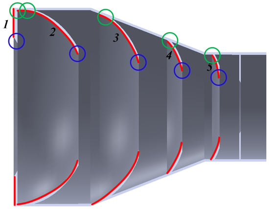
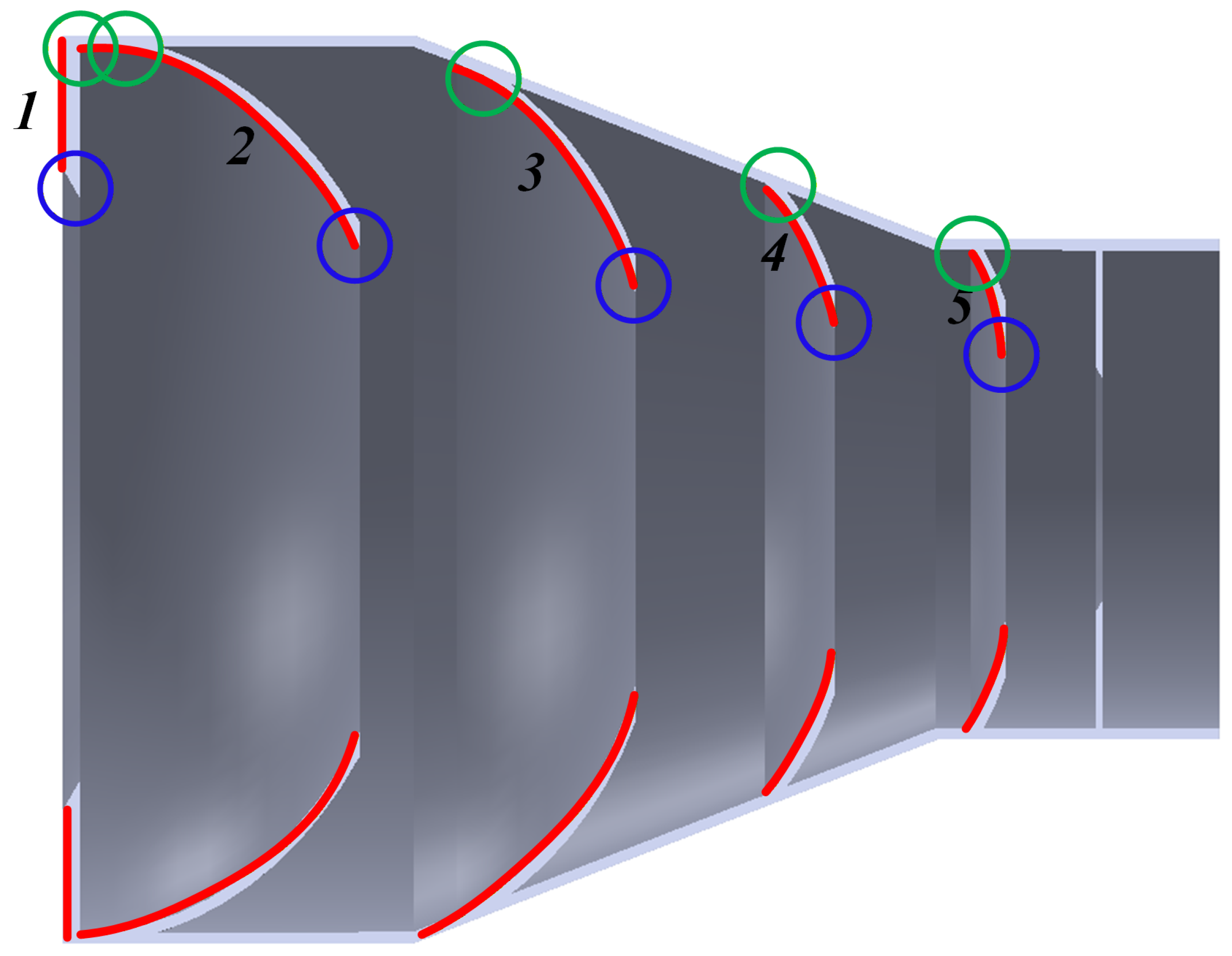
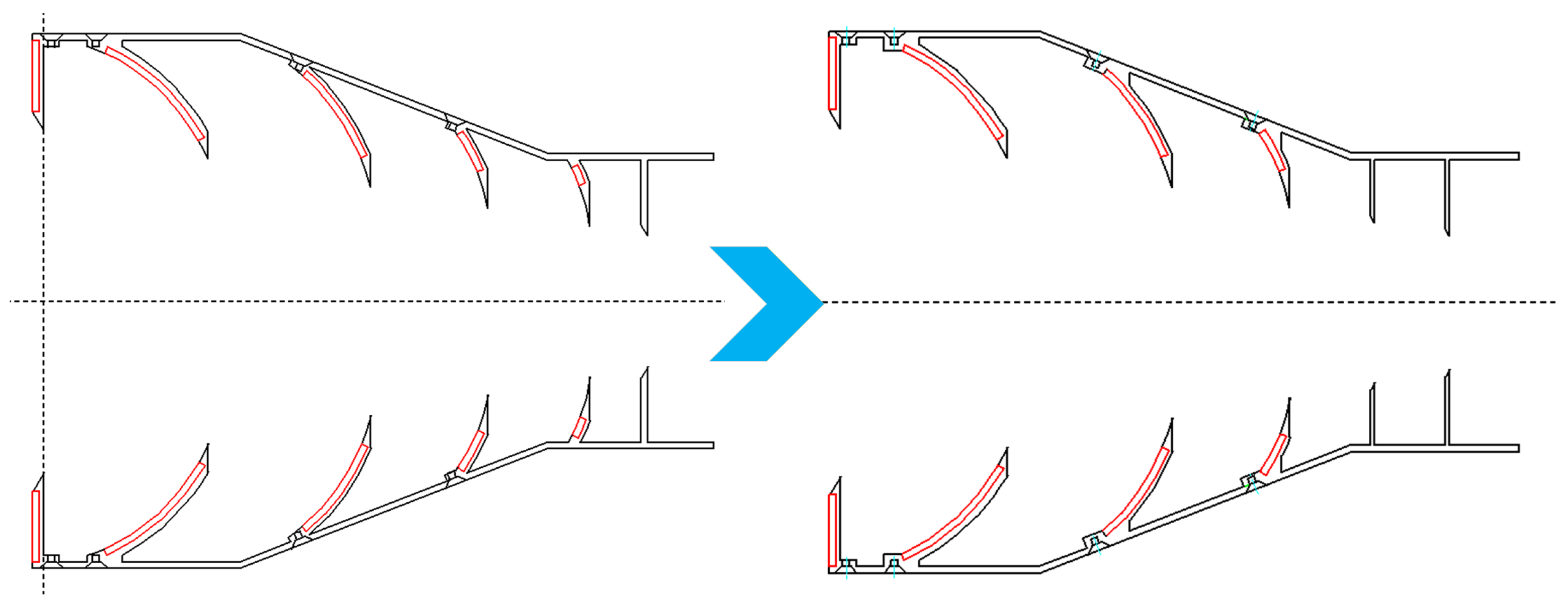
- Surface figure and edge precision limitations: The ellipsoidal vanes must simultaneously meet the requirements for surface figure accuracy, edge precision, and local surface finish. However, the overall baffle size is relatively small, and the internal cavity is highly constrained. As shown in Figure 16, integrated fabrication makes it difficult to ensure the surface accuracy of the ellipsoidal profiles of vanes 2, 3, 4, and 5.Figure 16. Regionsof the reflective ellipsoidal vanes requiring split fabrication.
- Limited accessibility for internal blackening treatment: The subsequent blackening treatment of the internal cavity is difficult to implement. This difficulty is particularly evident on the rear surfaces of vanes 2, 3, 4, and 5, namely the sides facing the exit aperture. In these regions, spraying access is limited, and coating uniformity is difficult to guarantee.
- Restricted accessibility for reflective coating deposition: The front surfaces of vanes 2, 3, 4, and 5, namely the sides facing the entrance aperture, require high reflectivity. However, the integrated internal cavity structure restricts the accessibility and uniformity of the coating process. It is therefore difficult to satisfy the combined requirements for reflective efficiency and surface quality in the reflective ellipsoidal baffle.
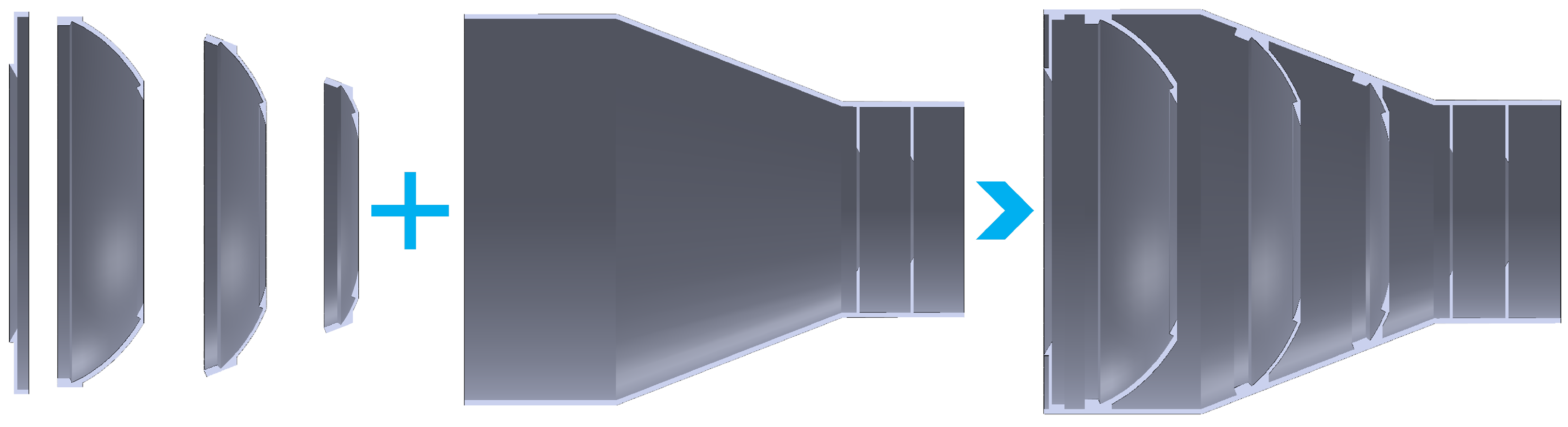
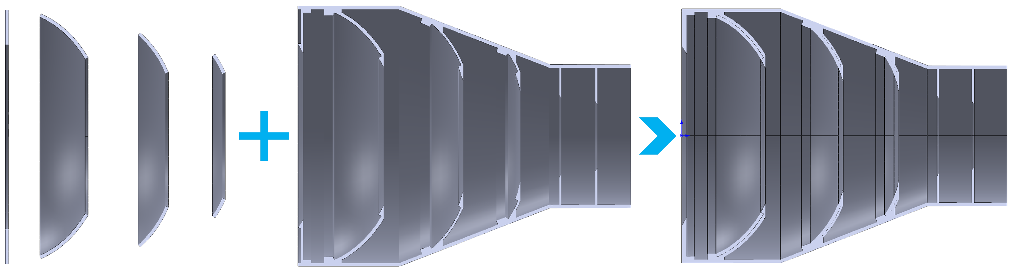
To address the foregoing issues, a split structure design is adopted to transform the ideal computational model into a manufacturable configuration. In this design, the baffle body, vane substrates, and critical reflective surfaces are functionally separated. This allows different optical surfaces to undergo machining, coating deposition, and blackening treatment independently. The specific optimisation strategies are summarised as follows.
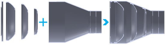
- Split design of the baffle body and vanes: The baffle body and vanes are designed as separate components. In this way, each vane is no longer constrained by the limited space inside the internal cavity. As a result, vanes 1, 2, 3, 4, and 5 can be machined individually. This approach helps improve the surface figure accuracy of each vane. It also facilitates the independent deposition of high reflectivity coatings on the front surfaces of the vanes.
- Functional separation of the front and rear vane surfaces: The front surface of each vane is mainly used to redirect incident stray light toward non-aperture regions or out of the baffle. Therefore, it requires a highly reflective surface. In contrast, the rear surface is mainly used to absorb residual scattered light. It therefore requires a black coating with high absorptance. Split fabrication reduces mutual interference between these two surface treatment processes. It is also beneficial for controlling the actual morphology and surface condition of the edge region indicated by the blue area in Figure 16.
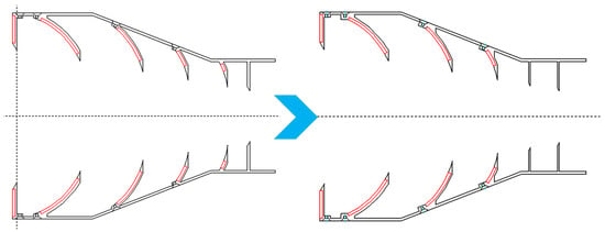
- Optimisation of assembly features and the terminal vane configuration: As indicated by the green region in Figure 16, threaded holes must be reserved at the bottom of each vane after the vanes are separated from the main baffle body. These holes ensure reliable assembly and positional constraint. Meanwhile, because of machining accuracy limitations, a certain manufacturing allowance must also be reserved in the edge region. Since the fifth vane is intrinsically small, its effective reflective area is already limited. After connection features and machining allowances are introduced, this area would be further reduced, as shown in Figure 17. Therefore, the fifth vane is ultimately optimised into a vertical configuration. This configuration provides a more appropriate balance among manufacturability, structural stability, and stray light suppression performance.Figure 17. Schematicdiagram of the split-structure design of the reflective ellipsoidal baffle.A completeassembly-tolerance sensitivity analysis was not performed in the present work. In practice, small axial or radial displacement and angular misalignment may slightly change the local shielding boundary and reflection path. However, the split interfaces are located outside the main clear aperture, and the designed light-trapping relationship among adjacent vanes is preserved. Systematic tolerance analysis will be included in future prototype optimisation.
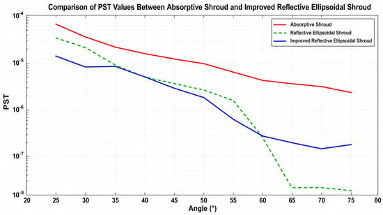
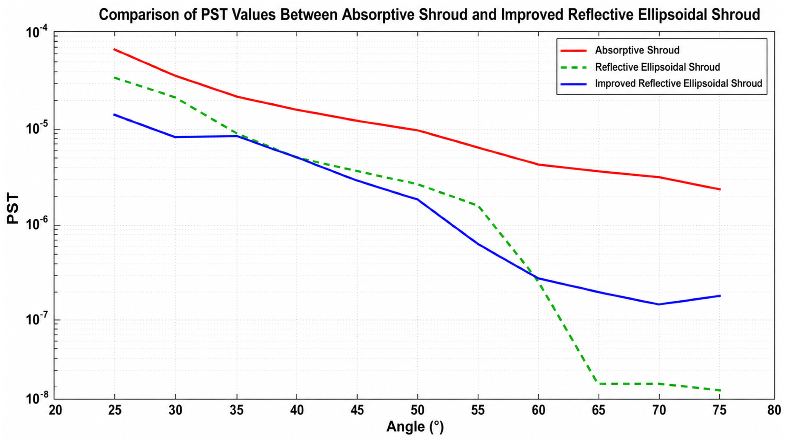
For the fifth vane, the original ellipsoidal form has a relatively small effective reflective area. After assembly holes, connection features, and machining allowance are introduced, the available reflective region is further reduced. Therefore, the fifth vane was optimised into a vertical configuration to improve manufacturability and structural reliability. The comparison between the ideal reflective ellipsoidal baffle and the optimised split baffle in Figure 18 indicates that the optimised structure maintains the overall PST suppression tendency after the fifth vane is changed to a vertical configuration.
Figure 18.
Comparison of the PST curves of the three baffles.
The final fabrication scheme is as follows. The outer wall of the reflective ellipsoidal baffle, the vane substrates, and the body of the absorptive baffle are fabricated by 3D printing. For the critical reflective regions of the reflective ellipsoidal vanes, single-point diamond turning is further performed after substrate fabrication. This process achieves higher surface figure accuracy and improved surface finish. This hybrid process combines the capability of 3D printing for complex structural fabrication with the precision of single-point diamond turning for critical optical surfaces. It therefore balances structural complexity, manufacturing feasibility, and optical performance.
Before the stray light suppression performance test, the final optimised split structure is simulated again in TracePro. It is then compared with both the absorptive baffle and the ideal reflective ellipsoidal baffle. This step verifies whether the baffle can maintain the expected stray light suppression capability after manufacturing constraints are introduced.
To further explain the thermal-radiation advantage of the reflective configuration, a simplified optical–thermal estimation was conducted. The irradiance at the baffle entrance was approximately . For the conventional absorptive baffle, the Q17 coating has an average absorptance of 97.91%, and the absorbed heat load per unit area can be estimated as
For the proposed reflective ellipsoidal baffle, the front surfaces of the vanes are aluminium reflective surfaces with an average spectral reflectance of 94.7%, and the directly absorbed heat load can be estimated as
Therefore, the direct absorbed heat load on the reflective front surface is approximately 5.4% of that on the Q17-coated absorptive surface, corresponding to a reduction of about 94.6%. Under similar heat-dissipation boundary conditions, this reduction in absorbed energy is expected to reduce the temperature rise and secondary infrared emission of the baffle structure. This estimation is simplified and does not replace direct thermal-radiation flux measurement or coupled optical–thermal simulation, which will be investigated in future work.
The optimised split reflective ellipsoidal baffle maintains the same overall PST suppression trend as the ideal reflective ellipsoidal model, while satisfying machining, coating, and assembly requirements. Although the split design introduces assembly interfaces, the main reflective path and light-trapping relationship are preserved. Therefore, the split configuration provides a practical balance between stray light suppression performance and manufacturability.
To further quantify the relative stray light suppression capability of the proposed baffle, the stray light suppression ratio (SLR) is introduced, as shown in Table 3. Based on the PST results, the improved reflective ellipsoidal baffle achieves an of 4.96–14.47 dB over the tested off-axis angle range. In particular, when the off-axis angle exceeds , the is higher than 10 dB, indicating that the proposed baffle reduces the residual stray light contribution by more than one order of magnitude compared with the conventional absorptive baffle. The highest SLR reaches 14.47 dB at an off-axis angle of . The split independent processing form of vanes and the baffle body is illustrated in Figure 19, and the complete assembly layout of the reflective ellipsoidal baffle is shown in Figure 20.
Table 3.
SLR values at different off-axis angles.
Figure 19.
Split design of the baffle vane and the baffle body.
Figure 20.
Assembly schematic of the reflective ellipsoidal baffle.
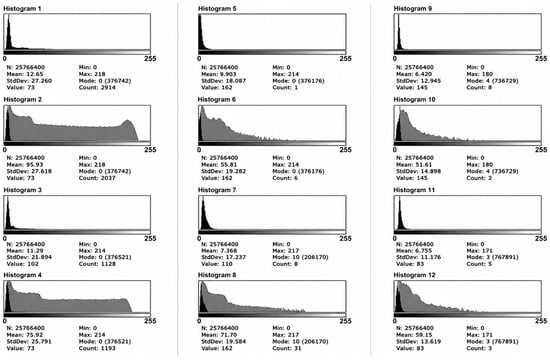
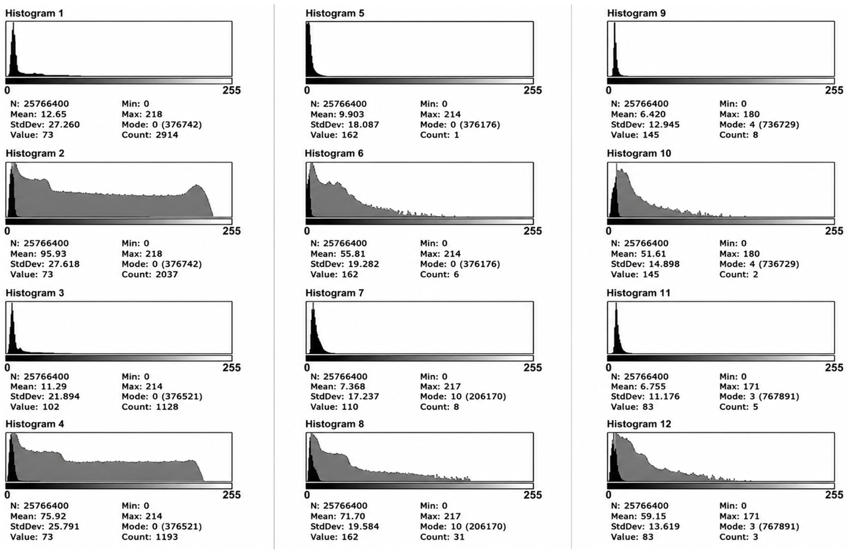
The pixel distribution of residual stray light under multiple off-axis angles is visualized via image-response histograms in Figure 21.
Figure 21.
Results of the image-response analysis.
5. Experimental Validation for Suppressing Infrared Imaging Degradation
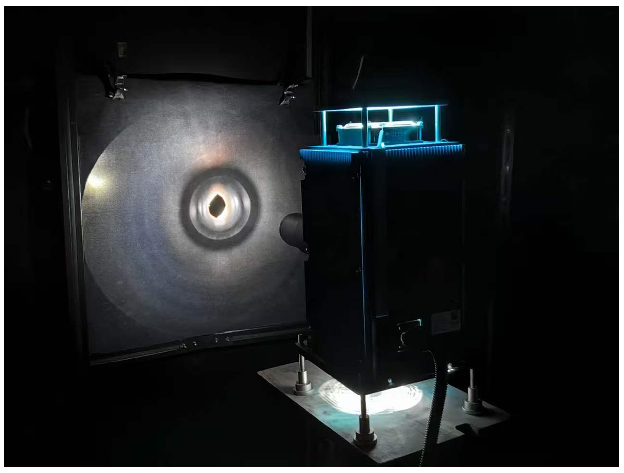
To verify the consistency between the computational simulation results and the actual stray light suppression performance, a darkroom experimental platform is established to test the baffles. In the experiment, the infrared camera is mounted on a high-precision rotary stage. It is equipped with the absorptive baffle and the split reflective ellipsoidal baffle in separate tests. A xenon lamp is used to simulate an external stray light source. The position and intensity of the light source are kept unchanged throughout the test. The relative angle between the camera and baffle assembly and the incident stray light is adjusted using the high-precision rotary stage. In this way, infrared images are obtained under different off-axis incidence conditions [3,24,28,32]. The entire experiment is conducted in a darkroom environment to minimise the influence of ambient illumination on the measurement results. The experimental setup is shown in Figure 22.
Figure 22.
Darkroom experimental setup under light-source illumination.
The infrared camera used in the experiment has a working wavelength band of 3–5 µm, a pixel size of 15 µm, a resolution of 640 × 512, a response linearity error lower than 1.2%, and a NETD not higher than 25 mK. The xenon lamp has a spectral range of 185–2000 nm, and the irradiance at the baffle entrance was approximately 1280 W/m2. The equivalent background gray-scale level of the darkroom was lower than 3. The relative uncertainty of the PST measurement was approximately 4.2%, and the relative uncertainty of the grey scale measurement was approximately 3.5%. The maximum alignment error among the camera, baffle, and light source was less than .
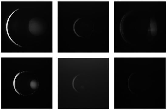
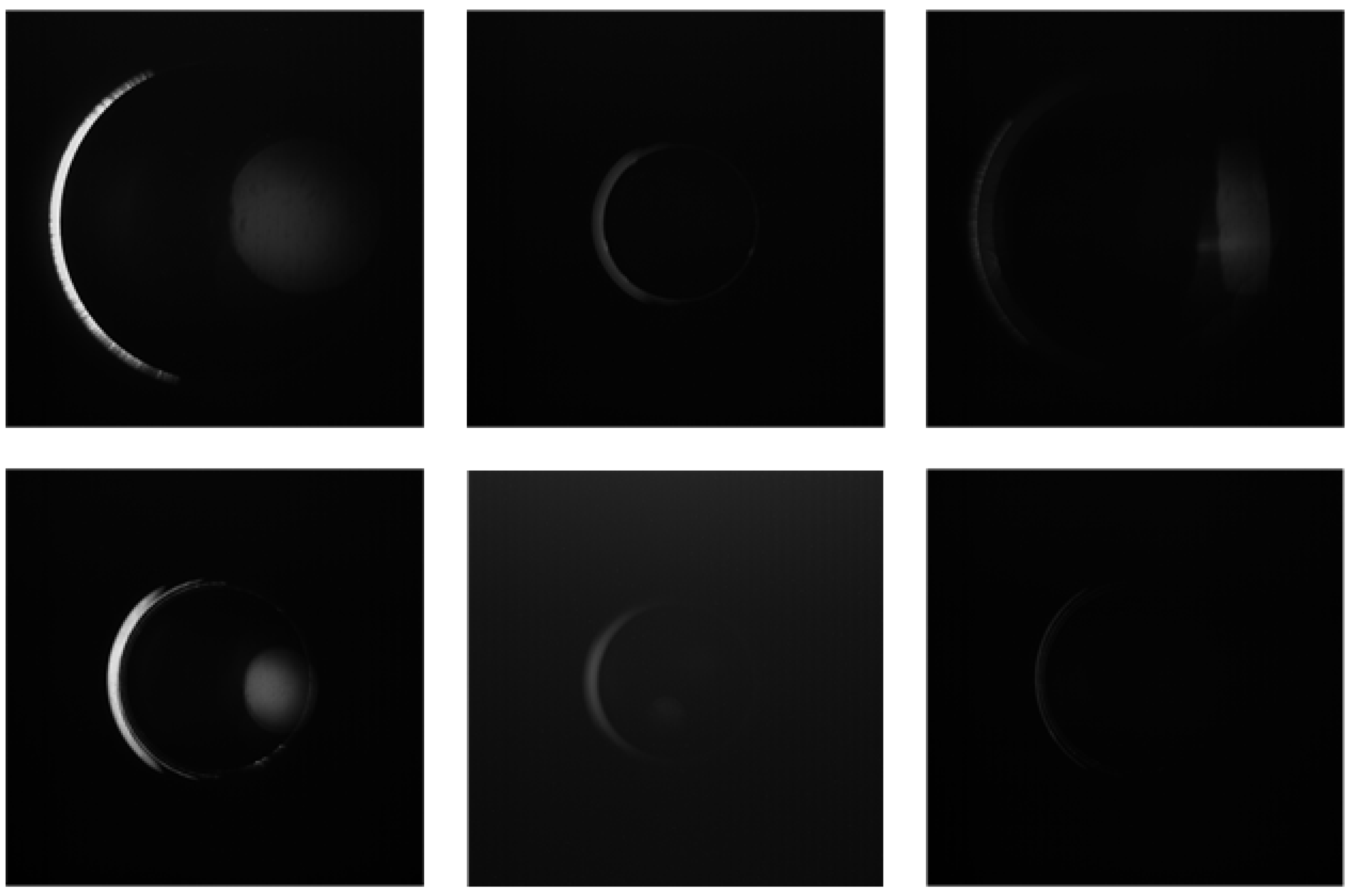
Under identical experimental conditions, test images are recorded at different off-axis angles. The stray light suppression results of the two baffles are shown in Figure 23. By comparing residual bright spots, background grey scale levels, and the spatial diffusion ranges of stray light in the images, the suppression differences between the two baffles can be visually assessed. This comparison reveals their relative effectiveness against external stray radiation.
Figure 23.
Stray-light suppression performance test of the baffles.
To quantitatively evaluate the stray light suppression capability of the baffles at the image-response level, grey scale response statistics are further calculated from the infrared test images acquired at different off-axis angles. For a test image obtained at an off-axis incidence angle , the baffle type is denoted by q. Here, represents the absorptive baffle, and represents the improved split reflective ellipsoidal baffle. Let denote the grey scale value recorded by the infrared camera at pixel position under the corresponding condition. Let denote the grey scale value of the dark field image. If no dark field image is separately acquired in the experiment, can be set to zero. To reduce the influence of dark current and fixed background response, background correction is first applied to the test image:
where denotes the background-corrected residual grey scale response. This value characterises the residual influence of stray light on the imaging plane. The same image evaluation region is selected for statistical analysis. Here, denotes the effective region used for grey scale evaluation, and represents the total number of pixels within this region. The mean grey scale response of residual stray light is defined as
where represents the mean residual grey scale value of baffle q at the off-axis angle . A smaller value indicates that less stray light enters the infrared camera. It also indicates a weaker contribution to background elevation in the image.
Furthermore, the grey scale standard deviation is calculated to evaluate the spatial nonuniformity of the residual stray light distribution:
where denotes the fluctuation degree of the grey scale response within the evaluation region. A larger value indicates more pronounced residual bright spots, local scattering, or nonuniform background response. In contrast, a smaller value suggests that the baffle more effectively suppresses local grey scale perturbations induced by stray light.
To further characterise the peak influence of strong stray light spots, the bright spot grey scale response is defined as
where denotes the set of the K pixels with the highest grey scale values in the evaluation region . Here, , corresponding to the top brightest pixels in the evaluation region. The metric represents the average grey scale response of the local strong bright spot region. Compared with the direct use of the maximum grey scale value, this metric reduces the influence of isolated abnormal pixels. It also provides a more stable characterisation of residual stray light spot intensity. Finally, the mean grey scale suppression ratio and bright spot suppression ratio are defined to quantify the performance of the improved reflective ellipsoidal baffle relative to the absorptive baffle:
where denotes the suppression ratio of the improved reflective ellipsoidal baffle relative to the absorptive baffle. This ratio is defined in terms of the mean background grey scale response. Similarly, denotes the suppression ratio for the local strong bright spot grey scale response. The term is a small constant introduced to avoid division by zero. If both and are positive and sufficiently large, the improved reflective ellipsoidal baffle can be considered effective. It reduces both the overall background grey scale elevation and the intensity of local strong stray light spots.
Based on the above metrics, ImageJ 1.54p is used to conduct grey scale statistical analysis and comparative evaluation of the test images. The results are shown in Figure 21. This evaluation method establishes a direct connection between the darkroom experimental images and the residual stray light response at the detector plane. It therefore validates the effectiveness of the optimised baffle structure from the perspective of imaging degradation suppression.
To quantitatively evaluate the consistency between the TracePro simulation and the experimental grey scale response, the simulated PST values and experimental mean grey scale values were normalised by their respective maximum values over the tested off-axis angles. The Pearson correlation coefficient between the normalised PST curve and the normalised mean grey scale-response curve was 0.962, indicating a strong positive correlation. The mean relative deviation between the two normalised curves was 7.83%. This deviation may be attributed to darkroom background noise, alignment errors among the light source, baffle, and camera, camera response nonlinearity, and small geometric differences between the simulation model and the fabricated prototype. These quantitative results further support the consistency between the simulation and experimental results.
The experimental results demonstrate that the improved reflective ellipsoidal baffle has stronger stray light suppression capability than the absorptive baffle. The experimental trend is also generally consistent with the TracePro simulation results. This consistency indicates that the proposed workflow can effectively characterise stray light propagation behaviour inside the baffle. The workflow includes realistic three-dimensional vane edge reconstruction, ray-tracing simulation, manufacturing-oriented structural optimisation, and darkroom experimental validation. These results further suggest that incorporating measured microtopographic information of critical surfaces into the computational optical model can improve the predictive accuracy of baffle design. It also provides experimentally verifiable engineering evidence for stray light suppression in complex infrared imaging environments.
6. Conclusions
This study proposes a split reflective ellipsoidal baffle to address infrared imaging degradation in internal radio telescope monitoring. In this application, infrared cameras are susceptible to solar radiation, convergent light reflected by the primary and secondary reflectors, and thermal radiation from structural components. The proposed configuration uses the reflective characteristics of ellipsoidal surfaces to constrain the propagation paths of out-of-field stray light. In addition, a computational stray light analysis framework is established. This framework integrates vane generatrix parameters, light trap propagation paths, and point source transmittance (PST) evaluation. Furthermore, a laser confocal microscope is used to acquire the realistic three-dimensional morphology of the vane edges. Based on the measured morphology, refined edge models suitable for ray-tracing simulation are constructed. The simulation results show that different edge models produce distinct PST responses. This indicates that edge microtopography has a measurable influence on stray light scattering behaviour. Among the tested configurations, the aluminium-alloy vane with a edge exhibits superior stray light suppression capability. On this basis, a manufacturing-oriented split structure optimisation is completed by combining 3D printing with single-point diamond turning. The effectiveness of the optimised baffle is then verified through TracePro simulation and darkroom stray light suppression experiments. In summary, this work integrates ellipsoidal geometric constraints, realistic edge microtopography, Monte Carlo ray tracing, PST evaluation, and experimental image grey scale response analysis. It establishes a computational analysis workflow that links structural parameters to the suppression of infrared imaging degradation. The proposed method provides a useful reference for upstream stray light control, imaging quality enhancement, and engineering optimisation of baffles in infrared imaging systems operating under complex optical and thermal environments. Future work may further incorporate measured BSDF data, coupled thermal radiation models, and more comprehensive image-quality evaluation metrics. These extensions could help establish a quantitative relationship between baffle structural parameters and infrared image degradation levels.
Author Contributions
W.H. and Y.J. contributed to methodology design and manuscript writing and editing. S.L., Y.L. and X.Z. provided financial support, laboratory resources, and experimental guidance. All authors have read and agreed to the published version of the manuscript.
Funding
This research was supported by the National Key R&D Programme of China under Grant 2021YFC2203501 entitled Real-time Surface Shape Regulation and Ultra-Wideband Pulse Technology for Large-Aperture Radio Telescopes, and the National Major Science and Technology Project of the New Generation Artificial Intelligence of the Ministry of Science and Technology of China under Grant 2022ZD0117301.
Data Availability Statement
All datasets used in this study are publicly available and ethically compliant. There are no competing interests associated with the data.
Conflicts of Interest
The authors declare that they have no known competing financial interests or personal relationships that could have influenced the work reported in this paper.
References
- Rogalski, A.; Kopytko, M.; Hu, W.; Martyniuk, P. Infrared HOT photodetectors: Status and outlook. Sensors 2023, 23, 7564. [Google Scholar] [CrossRef] [Scilit] [PubMed]
- Bianconi, S.; Mohseni, H. Recent advances in infrared imagers: Toward thermodynamic and quantum limits of photon sensitivity. Rep. Prog. Phys. 2020, 83, 044101. [Google Scholar] [CrossRef] [Scilit] [PubMed]
- Clermont, L.; Blain, P.; Khaddour, W.; Uhring, W. Unlocking stray light mysteries in the CoRot baffle with the time-of-flight method. Sci. Rep. 2024, 14, 6171. [Google Scholar] [CrossRef] [Scilit] [PubMed]
- Ge, S.; Luo, X.; Feng, S.; Wang, B. Sparsity and self-similarity priors guided deep learning for blind image super-resolution. J. Infrared Millim. Waves 2025, 44, 430–443. [Google Scholar]
- Qiao, M.; Zhang, Y.; Yang, H.; Bai, L.; Dong, X.; Zhang, T.; Liu, J.; Liu, F.; Gigan, S.; Shao, X. Harnessing forward scattering effect for high dynamic imaging. Photonix 2025, 6, 41. [Google Scholar] [CrossRef] [Scilit]
- Sun, L.; Cui, Q.; Xie, N.; Wang, J. Design of a built-in baffle for a Ritchey–Chretien optical system. Appl. Opt. 2018, 57, 10264–10270. [Google Scholar] [CrossRef] [Scilit] [PubMed]
- Han, P.; Guo, J.; Bao, Q.; Qin, T.; Ren, G.; Liu, Y. Optical design and stray light control for a space-based laser space debris removal mission. Appl. Opt. 2021, 60, 7721–7730. [Google Scholar] [CrossRef] [Scilit] [PubMed]
- Wei, L.; Yang, L.; Fan, Y.-P.; Cong, S.-S.; Wang, Y.-S. Research on stray-light suppression method for large off-axis three-mirror anastigmatic space camera. Sensors 2022, 22, 4772. [Google Scholar] [CrossRef] [Scilit] [PubMed]
- Li, J.; Yang, Y.; Qu, X.; Jiang, C. Stray light analysis and elimination of an optical system based on the structural optimization design of an airborne camera. Appl. Sci. 2022, 12, 1935. [Google Scholar] [CrossRef] [Scilit]
- Wang, C.-C.; Wei, L.-M.; Tian, X.; Zhang, L.; Xie, Y. New baffle design and analysis of long-wave infrared camera. Optik 2021, 242, 166820. [Google Scholar] [CrossRef] [Scilit]
- Zhang, H.; Sun, X.; Yang, J.; Liu, Y.; Wang, Y.; Tong, W. Design and Experiment of a Reflective Baffle Based on High-Modulus Carbon Fiber Composite Materials. Coatings 2026, 16, 234. [Google Scholar] [CrossRef] [Scilit]
- Zhang, C.J.; Zhong, H.W.; Zhao, Q.; Guo, R.F.; Liu, C.; Du, W.J. Design of WFOV single-lens based on improved genetic algorithm optimization. Opto-Electron. Eng. 2025, 52, 250083. [Google Scholar] [CrossRef]
- Zhang, Z.Y.; Chang, J.; Huang, Y.F.; Chen, Q.F.; Wu, Y.N. Reinforcement learning-based stray light suppression study for space-based gravitational wave detection telescope system. Opto-Electron. Eng. 2024, 51, 230210. [Google Scholar] [CrossRef]
- Zhang, Y.H.; Zhong, Z.Q.; Zhang, B. Analysis of surface scattering characteristics of ultra-smooth optical components in gravitational wave detection system. Opto-Electron. Eng. 2023, 50, 230222. [Google Scholar] [CrossRef]
- Xie, X.; Zhu, J.; Zhao, Z.; Shen, W. Optimize design of thermal infrared reflective baffle. In Proceedings of the Advanced Fiber Laser Conference (AFL2022); SPIE: Bellingham, WA, USA, 2023; Volume 12595, pp. 143–152. [Google Scholar]
- Yeon, H.N.; Hong, D.K.; Lee, C.; Lee, J.H.; Park, K.-W. Optimized baffle design for the simultaneous suppression of external and internal stray light in an LWIR catadioptric optical payload. Curr. Opt. Photonics 2025, 9, 65–71. [Google Scholar]
- Liao, Y.; Gao, S.; Bai, J.; Wang, K. General design algorithm for stray light suppression of a panoramic annular system. Opt. Express 2023, 31, 23491–23506. [Google Scholar] [CrossRef] [Scilit] [PubMed]
- Liang, R.; Zhou, X.; Xu, H.; Wu, D.; Li, C.; Yu, W. Optimal design of a gravitational wave telescope system for the suppression of stray light. Appl. Opt. 2024, 63, 1995–2003. [Google Scholar] [CrossRef] [Scilit] [PubMed]
- Jiang, H.; Niu, X. Stray light analysis and suppression of the visible to terahertz integrated cloud detection optical system. Sensors 2023, 23, 4115. [Google Scholar] [CrossRef] [Scilit] [PubMed]
- Zeng, C.; Xia, G.; Zhong, X.; Li, L.; Qu, Z.; Yang, Q.; Wang, Y. Fast stray light performance evaluation based on BSDF and radiative transfer theory. Sensors 2023, 23, 9182. [Google Scholar] [CrossRef] [Scilit] [PubMed]
- Lu, X.; Gross, H. Efficient simulation of surface scattering in symmetry-free optical systems. Opt. Express 2020, 28, 39368–39386. [Google Scholar] [CrossRef] [Scilit] [PubMed]
- Ben, C.; Shen, H.; Yu, X.; Meng, L.; Cheng, H.; Jia, P. Stray light analysis and suppression for an infrared Fourier imaging spectrometer. Photonics 2024, 11, 173. [Google Scholar] [CrossRef] [Scilit]
- Liu, H.; Liu, C.; Xie, P.; Liu, S.; Wang, X.; Zhang, Y.; Song, W.; Zhao, Y. Stray light analysis and suppression of high-resolution camera line-of-sight variation real-time monitoring system (LoS Var RTMS). Opt. Express 2024, 32, 24184–24199. [Google Scholar] [CrossRef] [Scilit] [PubMed]
- Xu, Z.; Liu, D.; Yan, C.; Hu, C. Stray light nonuniform background correction for a wide-field surveillance system. Appl. Opt. 2020, 59, 10719–10728. [Google Scholar] [CrossRef] [Scilit] [PubMed]
- Chen, M.; Zhao, Y.; Yang, W.; Qian, J.; Li, S.; Zheng, Y.; Ma, J.; Wang, S.; Chen, J.; Wei, J. A model for suppressing stray light in astronomical images based on deep learning. Sci. Rep. 2024, 14, 27521. [Google Scholar] [CrossRef] [Scilit] [PubMed]
- Fu, S.; Cheng, F.; Tjahjowidodo, T.; Zhou, Y.; Butler, D. A non-contact measuring system for in-situ surface characterization based on laser confocal microscopy. Sensors 2018, 18, 2657. [Google Scholar] [CrossRef] [Scilit] [PubMed]
- Nurunnabi, A.; Sadahiro, Y.; Laefer, D.F. Robust statistical approaches for circle fitting in laser scanning three-dimensional point cloud data. Pattern Recognit. 2018, 81, 417–431. [Google Scholar] [CrossRef] [Scilit]
- Ma, B.; Chen, Q.; Wang, H.; Xue, Y.; Ma, Z.; Liu, J. Stray light measurement for space optical systems using the time-domain method. Opt. Express 2025, 33, 9834–9846. [Google Scholar] [CrossRef] [Scilit] [PubMed]
- Ngo, T.D.; Kashani, A.; Imbalzano, G.; Nguyen, K.T.Q.; Hui, D. Additive manufacturing (3D printing): A review of materials, methods, applications and challenges. Compos. Part B Eng. 2018, 143, 172–196. [Google Scholar] [CrossRef] [Scilit]
- Rolland, J.P.; Davies, M.A.; Suleski, T.J.; Evans, C.; Bauer, A.; Lambropoulos, J.C.; Falaggis, K. Freeform optics for imaging. Optica 2021, 8, 161–176. [Google Scholar] [CrossRef] [Scilit]
- Shen, Z.; Yu, J.; Song, Z.; Chen, L.; Yuan, Q.; Gao, Z.; Pei, S.; Liu, B.; Ye, J. Customized design and efficient fabrication of two freeform aluminum mirrors by single point diamond turning technique. Appl. Opt. 2019, 58, 2269–2276. [Google Scholar] [CrossRef] [Scilit] [PubMed]
- Clermont, L.; Uhring, W.; Georges, M. Stray light characterization with ultrafast time-of-flight imaging. Sci. Rep. 2021, 11, 10081. [Google Scholar] [CrossRef] [Scilit] [PubMed]


Disclaimer/Publisher’s Note: The statements, opinions and data contained in all publications are solely those of the individual author(s) and contributor(s) and not of MDPI and/or the editor(s). MDPI and/or the editor(s) disclaim responsibility for any injury to people or property resulting from any ideas, methods, instructions or products referred to in the content. |
© 2026 by the authors. Licensee MDPI, Basel, Switzerland. This article is an open access article distributed under the terms and conditions of the Creative Commons Attribution (CC BY) license.