1. Introduction
The global electric power system is undergoing a profound transformation, driven by the accelerating penetration of IBRs, AI technologies, the large-scale electrification of end-use sectors, and the emergence of highly concentrated, dynamically controlled load centers. This evolution is fundamentally reshaping traditional assumptions that have long underpinned power system analysis, planning, and operational security. Historically, power systems were dominated by synchronous machines, whose inherent inertia, predictable fault-current contribution, and relatively slow electromechanical dynamics enabled well-established modeling paradigms based on steady-state analysis and simplified dynamic representations. However, the increasing displacement of synchronous generation by converter-interfaced resources has introduced a fundamentally different system behavior characterized by low inertia, reduced short-circuit strength, and fast, control-driven dynamics [
1,
2].
In parallel, modern electrical demand is no longer passive. Emerging large-scale loads—such as hyperscale data centers, cryptocurrency mining facilities, hydrogen electrolysis plants, electrified transportation hubs, and advanced manufacturing complexes—are increasingly interfaced through power electronic converters and embedded energy management systems. These facilities exhibit characteristics that closely resemble those of generation assets, including size, controllability, and grid interaction capability [
3]. Their rapid growth and geographic concentration have been recognized by system operators and standards bodies, including the North American Electric Reliability Corporation (NERC), as significant reliability concerns. Therefore, NERC has issued multiple alerts and guidelines highlighting their potential impact on system adequacy, stability, and operational security [
4].
Unlike traditional industrial loads, which can be adequately represented by static ZIP or composite load models, modern large loads exhibit rapid temporal dynamics, voltage and frequency sensitivity, and, in some cases, programmable grid-support functionality. Recent disturbances have demonstrated that these facilities may unexpectedly disconnect during fault-induced voltage or frequency excursions, leading to secondary frequency drops, overvoltage conditions, and cascading system stress [
5,
6]. These behaviors are not fully captured by conventional positive-sequence phasor-based simulation tools, nor are they consistently represented in electromagnetic transient (EMT) frameworks due to the lack of standardized dynamic load models and insufficient validation against field data. Consequently, there is an increasing need to revisit both modeling methodologies and grid planning criteria to ensure the accurate representation of these emerging behaviors [
7,
8,
9,
10].
Recent literature has addressed numerous aspects of converter-dominated power systems, including inverter stability, grid-forming and grid-following control, reactive power support [
11,
12], demand flexibility [
13], system strength [
14,
15,
16], energy storage integration for interconnected microgrids [
17,
18,
19], and the challenges associated with their interaction with active loads [
20,
21,
22,
23]. However, most existing studies focus on individual topics and do not provide a unified perspective that simultaneously captures large-load dynamics, energy storage behavior, protection challenges, system-strength assessment, and grid-code compliance. Consequently, there remains a lack of a unified, holistic framework that simultaneously captures large-scale load dynamics, system strength and inertia variability, protection coordination challenges, and the coupled, multi-timescale behavior of energy storage and converter-based resources.
In addition, many prevailing analytical approaches continue to rely on steady-state metrics, most notably the SCR, to assess system strength and stability. However, such indices are increasingly inadequate for representing the dynamic, frequency-dependent, and control-interaction-driven instabilities that characterize modern low-inertia, power electronic-dominated grids. This limitation underscores the need for more comprehensive modeling and assessment methodologies capable of accurately capturing the complex, tightly coupled dynamics of future power systems, a central objective of this review [
24,
25,
26].
Motivated by the limitations of existing stability, protection, and planning frameworks, this article provides a structured and comprehensive technical review of modern power systems with high penetration of IBRs and large dynamic loads. The primary objective is to systematically consolidate and critically assess recent advances in modeling, control, protection, and energy storage integration, with an emphasis on their role in ensuring the stable operation of converter-dominated grids.
To further distinguish this work from existing review articles, the present study introduces a unified control-aware and impedance-informed perspective for assessing the interactions among inverter-based resources, large-scale dynamic loads, and energy storage systems in converter-dominated power systems. Rather than reviewing these domains independently, the proposed perspective emphasizes their coupled influence on system strength, stability margins, protection performance, and grid-code compliance.
The primary contributions of this review can be summarized as follows:
A comprehensive synthesis of the evolving characteristics of large power electronic loads and their implications for power system planning, operation, and reliability.
A structured classification of high-energy, high-power, and hybrid energy storage technologies, with an emphasis on their dynamic support capabilities in low-inertia systems.
A critical assessment of emerging grid-code requirements, including fault ride-through capability, system-strength evaluation, and protection coordination challenges under high inverter penetration.
A comparative discussion of traditional system-strength metrics and emerging impedance-based approaches for stability assessment in converter-dominated networks.
The development of a unified control-aware assessment framework that links large-load dynamics, converter controls, energy storage behavior, and grid-code compliance considerations within a common analytical perspective.
Although this article is primarily structured as a technical review, the discussion is organized around a control-aware assessment philosophy in which converter controls, network characteristics, large-load behavior, and energy storage dynamics are treated as interacting components of a common stability and compliance framework.
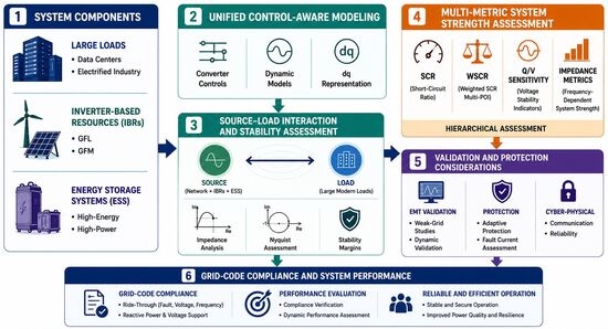
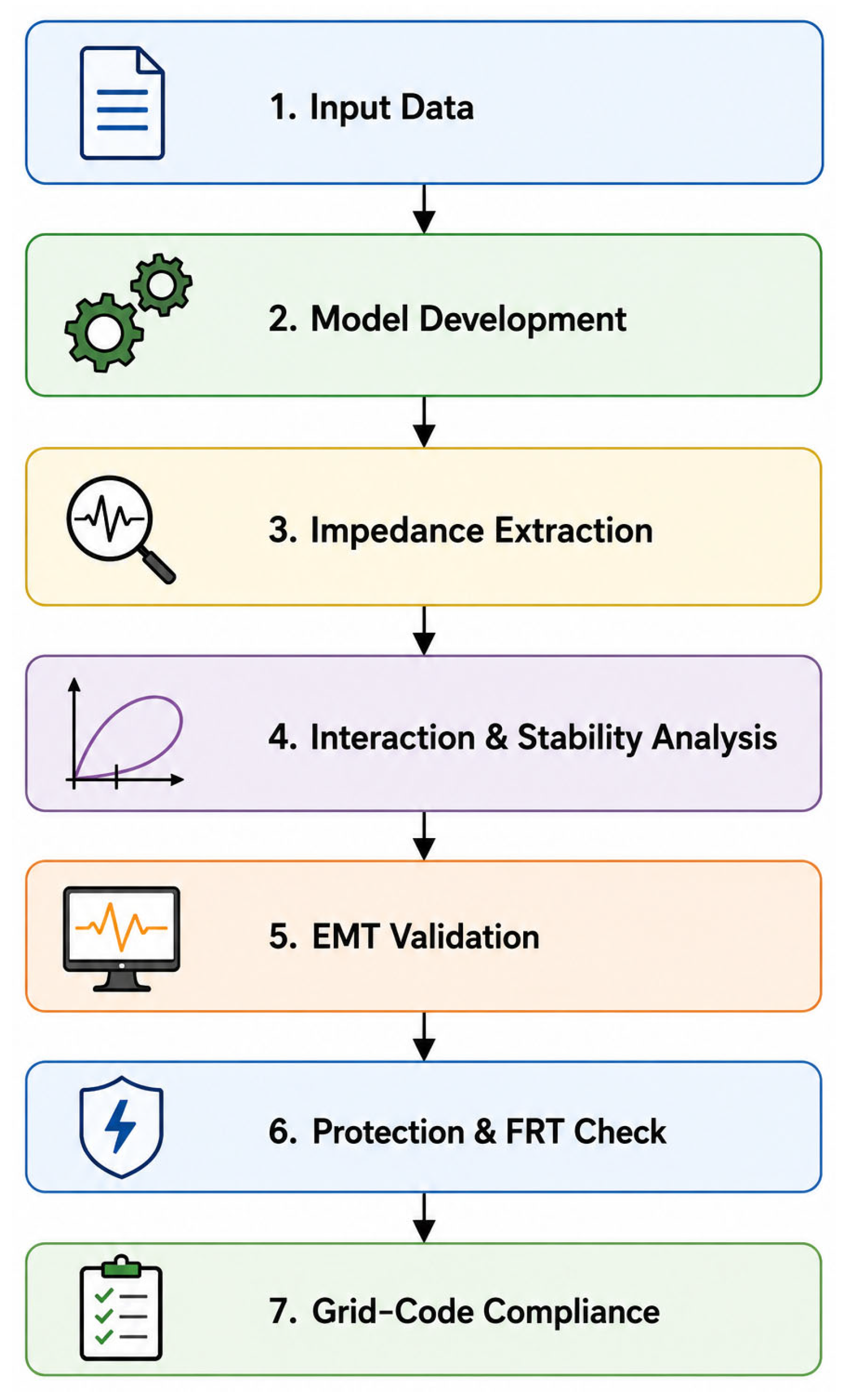
Figure 1 presents the proposed control-aware and impedance-informed assessment framework that forms the analytical foundation of the study and guides the subsequent discussion of large loads, energy storage systems, system strength, protection, and grid-code compliance.
The remainder of this article is organized as follows:
Section 2 introduces the proposed control-aware and impedance-informed assessment framework.
Section 3 and
Section 4 examine large-load integration challenges and energy storage technologies, respectively.
Section 5 discusses grid-code requirements, system-strength assessment, and protection considerations.
Section 6 highlights research gaps and emerging directions, while
Section 7 concludes the paper.
2. Proposed Control-Aware and Impedance-Informed Assessment Framework
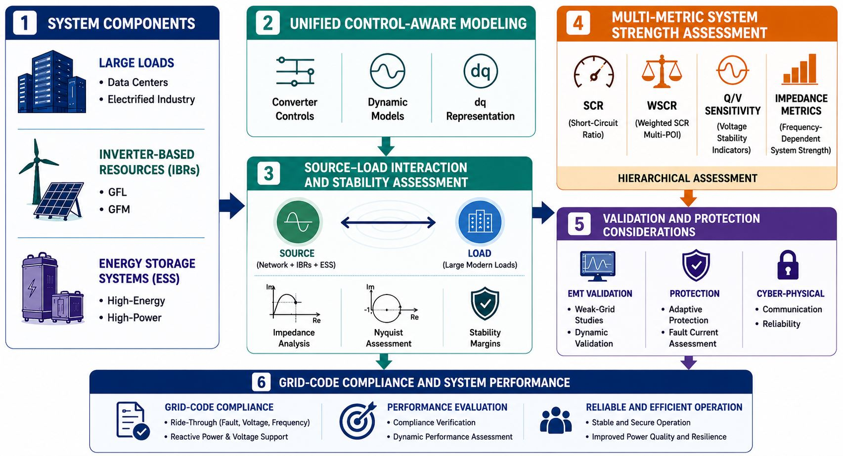
The objective of the proposed framework is to establish a unified assessment methodology capable of linking network characteristics, converter controls, large-load behavior, energy storage dynamics, protection performance, and grid-code compliance within a single analytical structure. Unlike conventional planning approaches that evaluate these elements independently, the proposed framework treats them as dynamically coupled subsystems whose interactions collectively determine system performance.
2.1. Framework Architecture
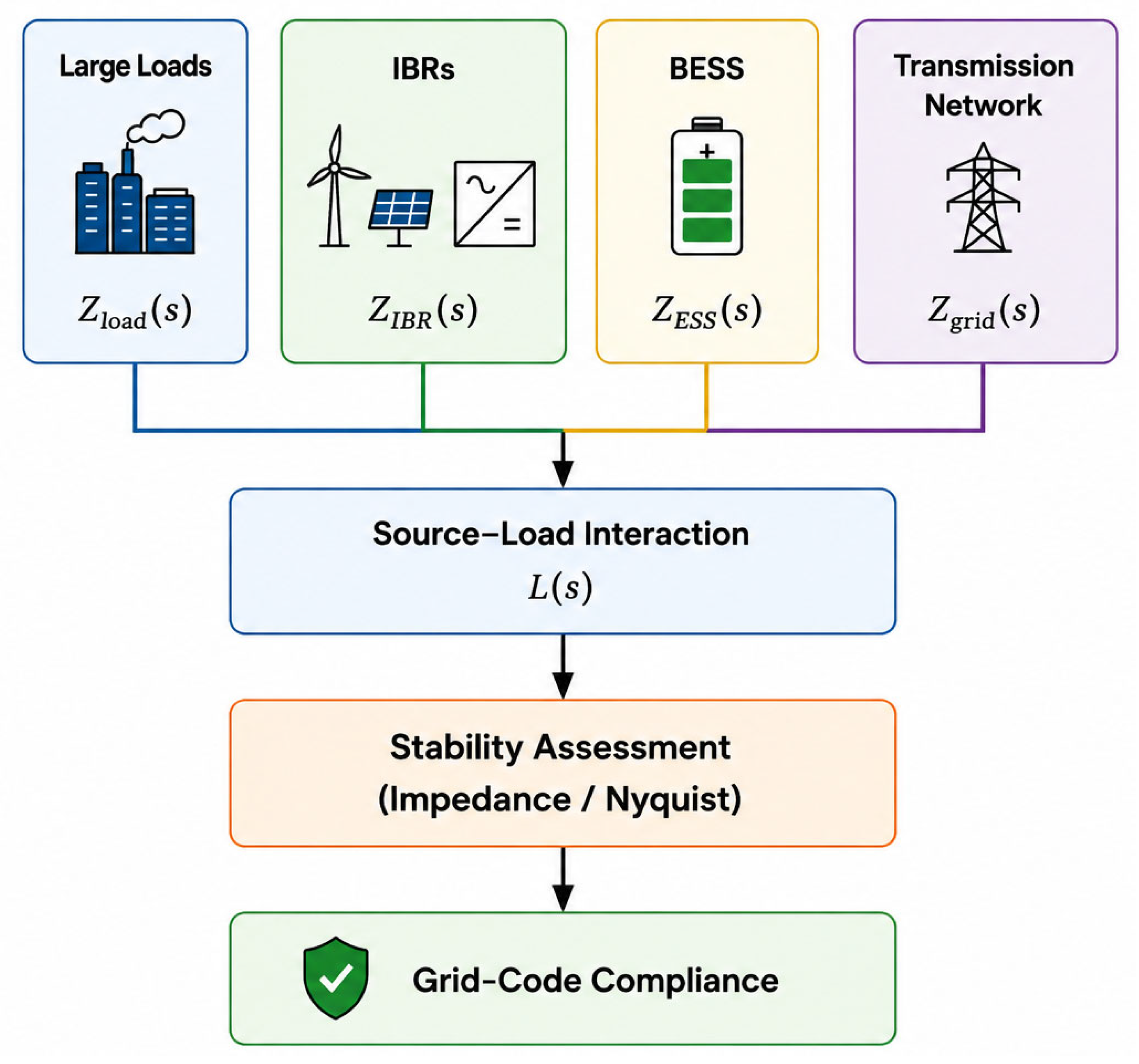
Figure 2 illustrates the architecture of the proposed framework. The assessment process begins with the development of equivalent representations for the transmission network, inverter-based resources, large electrical loads, and energy storage systems. These subsystem models are subsequently combined to establish a system-level representation that captures the dominant interaction pathways influencing stability and compliance performance. The key inputs required for implementation are summarized in
Table 1.
2.2. Dynamic Representation of System Components
To enable a common analytical treatment, the overall system is represented through an equivalent aggregated dynamic impedance model defined as [
27,
28]:
where
denotes the equivalent frequency-dependent impedance observed at the point of interconnection. In this conceptual formulation:
represents the equivalent impedance of large power electronic loads and captures the aggregate dynamic response of load-management systems, converter interfaces, and disturbance-response logic.
represents the impedance of battery energy storage systems and reflects the dynamic behavior associated with voltage regulation, frequency support, and power-sharing functions.
represents the equivalent impedance of the external transmission network and characterizes the frequency-dependent electrical behavior observed at the interconnection boundary.
represents the impedance of converter-interfaced generation resources, incorporating the effects of current regulators, outer control loops, synchronization mechanisms, and operating mode selection [
27,
28].
The operating mode of inverter-based resources significantly influences the resulting impedance characteristics. In grid-following (GFL) operation, converters rely on PLL-based synchronization and behave as controlled current sources referenced to the external grid voltage, making their impedance characteristics more sensitive to weak-grid conditions and converter–network interactions [
28]. In contrast, grid-forming (GFM) converters establish an internal voltage and frequency reference and operate as controlled voltage sources, generally providing stronger voltage support and improved performance under low-SCR conditions [
29].
Accordingly, the proposed framework explicitly accommodates both GFL and GFM operating modes through the converter impedance representation
, enabling their impacts on source–load interactions, system-strength assessment, and grid-code compliance to be evaluated within a common analytical framework [
29].
Table 2 summarizes the principal differences between grid-following and grid-forming operation from the perspective of dynamic system assessment.
By expressing all major subsystems within a common impedance-based framework, the formulation enables the direct evaluation of system interactions and stability characteristics across a wide frequency range.
2.3. Source–Load Interaction Analysis
Once the equivalent subsystem models have been established, the stability assessment is performed by evaluating the dynamic interaction between source-side and load-side subsystems using established impedance-based stability assessment principles [
27,
30]. This interaction is represented by the source–load interaction function as follows:
where
characterizes the frequency-dependent coupling between source and load dynamics [
27]. In this formulation,
denotes the equivalent source impedance, which incorporates the combined dynamic behavior of the transmission network, inverter-based resources, and energy storage systems. The load admittance matrix
is defined as:
where
represents the aggregate dynamic impedance of large electrical loads and their associated control systems [
30].
The interaction function provides a direct measure of the coupling between source-side and load-side dynamics and serves as the basis for identifying operating conditions that may result in resonance, oscillatory behavior, or reduced stability margins. By incorporating both electrical-network characteristics and control-system dynamics, the formulation offers a more comprehensive representation of system behavior than conventional short-circuit-based metrics and remains applicable across a wide range of operating conditions [
27,
30].
2.4. Stability Assessment Procedure
The stability evaluation process is performed using frequency-domain analysis of the interaction function. The frequency response of
L(
S) is evaluated over the frequency range relevant to converter–control dynamics, network resonances, and load–control interactions. The resulting response is subsequently assessed using the generalized Nyquist stability criterion [
27,
30].
According to this criterion, stability is maintained when the Nyquist trajectory does not produce an inadmissible encirclement of the critical point (−1, j0). The distance between the trajectory and the critical point further provides a quantitative indication of the available stability margin [
27]. This approach enables the identification of:
Control-driven oscillatory modes;
Resonance conditions;
Weak-grid interaction phenomena;
Adverse coupling between large loads and converter-based resources;
Degradation of stability margins under changing operating conditions.
Consequently, the methodology extends beyond conventional system-strength indicators by directly evaluating the mechanisms responsible for instability [
27,
29,
30].
2.5. Framework Implementation Workflow
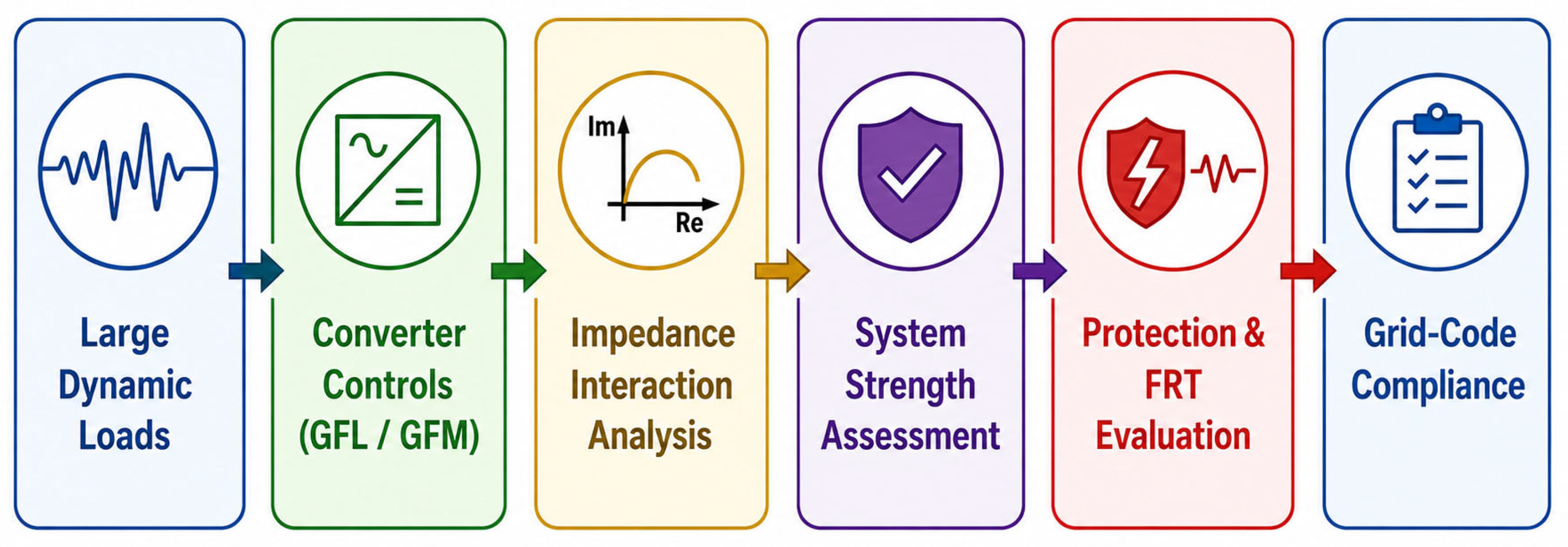
The practical implementation of the proposed methodology follows a structured sequence of analytical and simulation-based steps as shown in
Figure 3. Initially, network data, equipment ratings, and control parameters are collected from planning studies, manufacturer models, and interconnection documentation. Equivalent dynamic models are subsequently developed for the network, inverter-based resources, energy storage systems, and large loads.
Following model development, dq-domain impedance extraction is performed using small-signal perturbation techniques, frequency scanning procedures, or impedance-identification methods derived from EMT simulations [
28,
30]. The resulting subsystem models are then combined to establish the overall system representation.
The next stage consists of frequency-domain stability analysis, during which potential resonance conditions and interaction mechanisms are identified. Stability margins are subsequently quantified through Nyquist-based assessment.
Finally, the most critical operating conditions identified during the analytical stage are evaluated using EMT simulations [
31,
32]. This final validation stage confirms dynamic performance under severe disturbances and provides direct verification of compliance with ride-through requirements, voltage-support obligations, frequency-response criteria, and protection coordination requirements.
Through this workflow, the proposed framework establishes a direct connection between analytical stability assessment and practical grid-code compliance evaluation, thereby providing a structured methodology for the study of future converter-dominated power systems.
While the preceding workflow defines the implementation procedure of the proposed framework, its practical relevance is best understood in the context of the growing industry adoption of EMT-based assessment methodologies for converter-dominated power systems [
31,
32,
33].
2.6. Practical Applicability and EMT-Based Validation of the Proposed Framework
The increasing penetration of inverter-based resources (IBRs), battery energy storage systems (BESSs), and large power electronic loads, particularly hyperscale data centers, has significantly increased the importance of electromagnetic transient (EMT) assessment in modern power-system planning and interconnection studies. Unlike conventional phasor-domain approaches, EMT simulations explicitly represent converter controls, electromagnetic interactions, and unbalanced system conditions, thereby enabling the analysis of dynamic phenomena that increasingly govern the behavior of converter-dominated power systems. Consequently, EMT-based assessment has become an essential component of modern planning, system-strength evaluation, and interconnection methodologies for future grids [
32,
33,
34].
Recent experiences reported by transmission system operators in Australia, Texas, Denmark, and Finland have demonstrated that simplified Single-Machine Infinite Bus (SMIB) representations may not adequately reproduce the dynamic responses observed in large-scale converter-dominated networks. Comparative investigations showed that large-scale EMT models often exhibit substantially different voltage trajectories, active power responses, and post-fault recovery characteristics compared with equivalent SMIB studies. These differences arise primarily from converter-to-converter interactions, network-wide control coupling, and the influence of neighboring inverter-based resources, which are largely absent in simplified equivalent representations. As a result, system operators increasingly rely on large-scale EMT studies whenever weak-grid conditions, high IBR penetration levels, or significant converter interactions are anticipated [
31].
The practical implications of these findings extend beyond renewable generation. Recent grid-level studies of hyperscale data centers have shown that large transmission-connected power electronic loads may exhibit dynamic behaviors comparable to those of inverter-based generation facilities. Converter controls, ride-through functions, and fast power electronic responses can influence voltage recovery, fault behavior, and local system stability, thereby requiring modeling approaches capable of capturing sub-cycle electromagnetic interactions and control-driven dynamics [
34]. These observations reinforce the need for assessment methodologies that explicitly account for both generation-side and load-side converter behavior.
Although EMT simulations provide the highest level of modeling fidelity, they require detailed vendor-specific models, extensive network representations, and substantial computational resources. Large-scale EMT studies often involve network partitioning, parallel processing architectures, and advanced model management techniques to maintain practical simulation times [
31,
33]. Consequently, utilities and system operators increasingly require intermediate assessment methodologies capable of identifying operating conditions that are most likely to require detailed EMT investigation before committing significant computational resources.
From this perspective, the proposed control-aware and impedance-informed framework complements rather than replaces EMT analysis. The framework provides a structured methodology for identifying conditions that may be susceptible to converter-driven stability issues by combining system-strength evaluation, impedance-based assessment techniques, control-aware representations, and compliance-oriented screening criteria within a unified analytical structure. In this manner, the framework serves as a practical bridge between conventional planning studies and detailed EMT investigations.
The value of such an approach is further supported by recent EMT-based investigations of converter-dominated systems. Detailed studies of BESS–PV microgrids have demonstrated that fault-current behavior, protection performance, and transient responses are strongly influenced by converter controls, current-limiting functions, and DC-link dynamics. These studies revealed that converter-dominated systems may exhibit fault characteristics and protection challenges that differ fundamentally from those observed in conventional synchronous-machine-based networks, thereby requiring detailed EMT assessment for accurate representation and validation [
35].
Similarly, modern interconnection studies increasingly require EMT analysis to evaluate weak-grid operation, converter interactions, fault ride-through performance, and system-strength limitations associated with IBRs, BESSs, HVDC systems, and large power electronic loads [
32]. Industry experience therefore indicates that EMT simulations are becoming an indispensable component of stability assessment; however, their computational complexity necessitates efficient methodologies for determining when detailed EMT analysis is required.
Accordingly, the proposed framework aligns with the growing industry adoption of EMT-supported planning methodologies. Rather than functioning as an alternative to EMT simulations, the framework provides a computationally efficient assessment layer that supports the identification of critical operating conditions, prioritization of stability investigations, and effective allocation of EMT simulation resources. This capability is expected to become increasingly valuable as future power systems continue to evolve toward higher penetrations of inverter-based resources, energy storage systems, grid-forming technologies, and hyperscale transmission-level power electronic loads [
31,
32,
33,
34,
35].
3. Grid Integration of Large Loads
Modern power systems are rapidly evolving due to the integration of large-scale transmission-level loads, including data centers, cryptocurrency mining facilities, hydrogen plants, EV fast-charging stations, and advanced manufacturing facilities. Unlike traditional, geographically dispersed demand, these loads are highly concentrated and comparable to large generation units. They are primarily interfaced via power electronic converters, enabling fast, coordinated responses to disturbances.
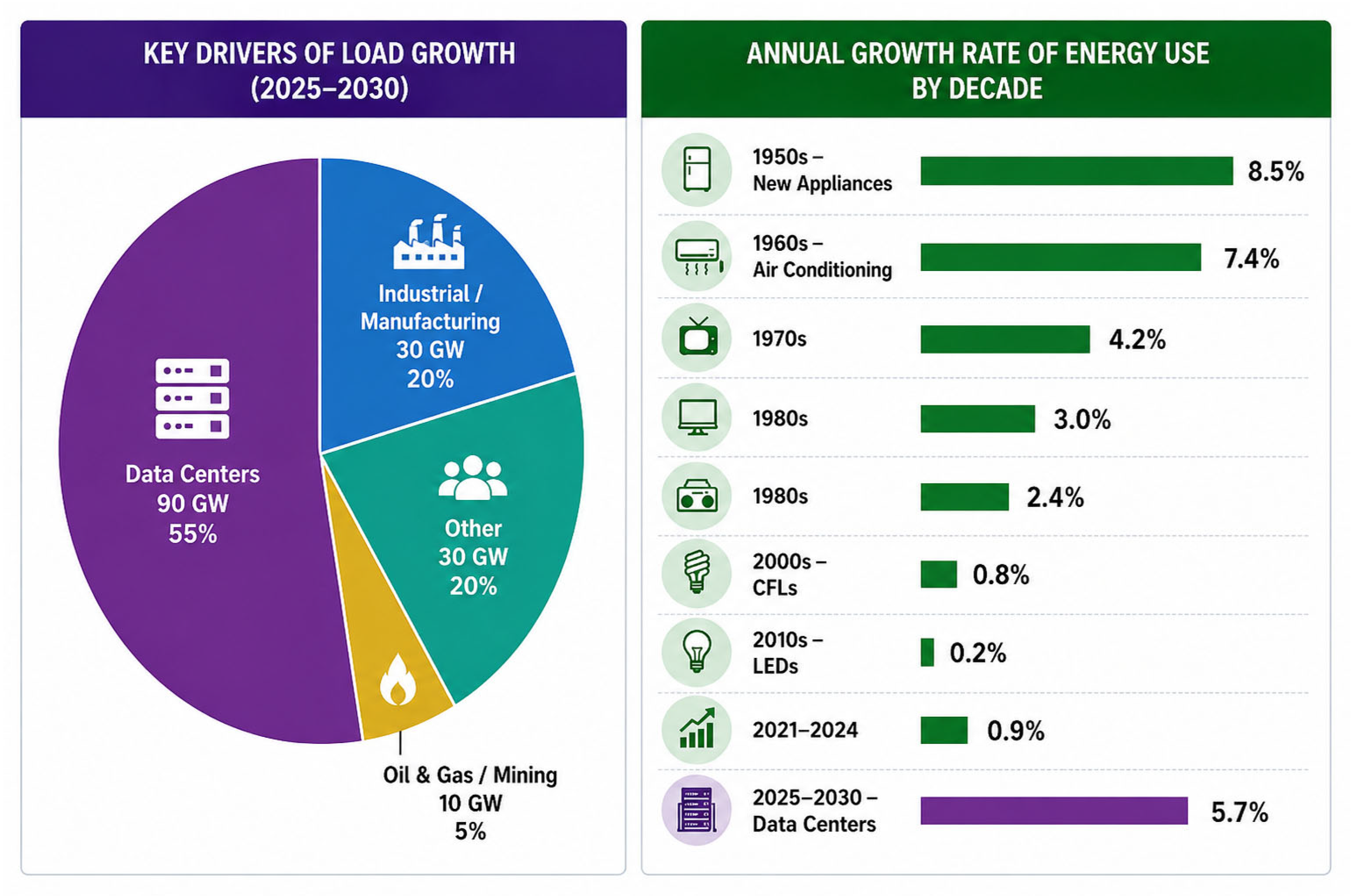
Figure 4 shows the growth of the electric load over the decades [
36].
This transformation significantly alters load characteristics. Historically, industrial loads were represented using composite models, with electromagnetic transient (EMT) models applied only to specific fast events, which was adequate for motor-dominated systems. In contrast, modern loads rely heavily on power electronic interfaces with advanced control and ride-through capabilities. Recent events have shown that such facilities may disconnect unexpectedly during fault clearance, potentially causing overvoltage, over-frequency, and cascading disturbances [
37,
38].
These dynamic behaviors are not well captured by existing load models or fully supported by current positive-sequence phasor-domain (PSPD) and EMT tools. Therefore, improved modeling approaches and clearer guidelines for selecting PSPD versus EMT simulations are required to ensure reliable transmission planning, accurate interconnection studies, and secure system operation [
38,
39].
From the perspective of the proposed control-aware and impedance-informed assessment framework introduced in
Section 2, large electrical loads constitute a critical component of the load-side dynamics governing source–load interactions. Their aggregate behavior directly influences the equivalent load representation used for stability assessment and therefore affects the system response observed during disturbances, restoration processes, and weak-grid operation. Accordingly, the accurate characterization of load dynamics is not only necessary for load modeling itself but also for establishing the analytical foundation required for impedance-based stability assessment and grid-code compliance evaluation.
The following sections examine the principal characteristics of modern large loads and develop the modeling domains required to represent their dynamic interactions with inverter-based resources, energy storage systems, and transmission networks.
3.1. Large Loads Characteristics and Grid Risks in Modern Energy Systems
Conventional loads, primarily induction motor–based, exhibited slow and predictable dynamics, allowing simplified representations such as ZIP and composite models to be sufficient for system studies. In contrast, modern large loads are dominated by converter-based technologies, including uninterruptible power supplies and variable-speed drives, introducing fast, control-driven behavior and heightened sensitivity to voltage and frequency deviations [
5,
39].
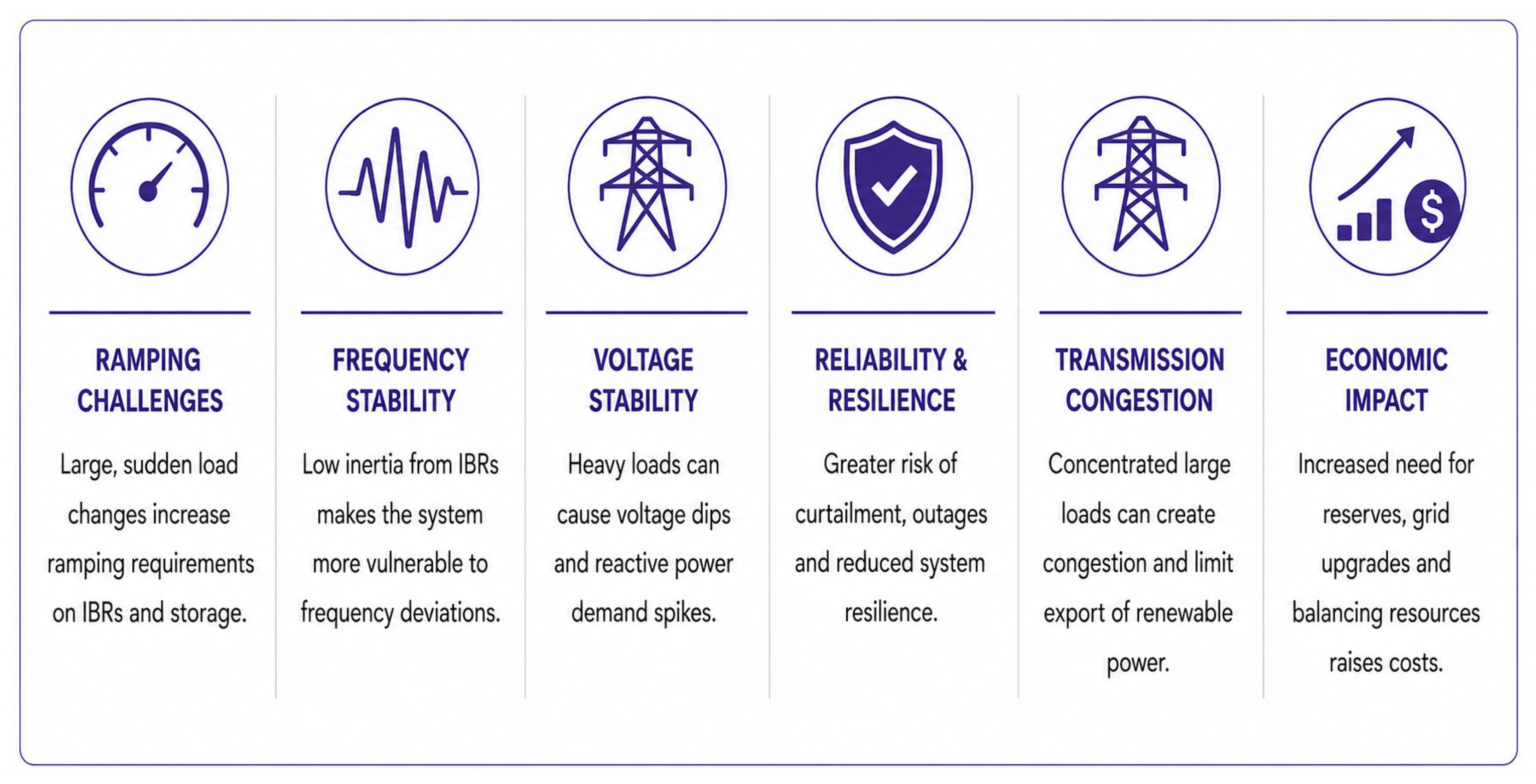
These features introduce additional complexity to system performance, particularly in voltage and frequency stability, and increase uncertainty in operational planning under low-inertia conditions associated with the high penetration of IBRs. As a result, they pose new technical challenges beyond those observed in traditional industrial demand [
39,
40].
Figure 5 highlights the impact of large loads with modern IBR-dominated energy systems.
At the same time, these loads offer capabilities such as demand flexibility, on-site storage, and embedded generation, which can be leveraged to support grid operation. This necessitates the evolution of planning, interconnection, and operational frameworks to effectively integrate such technologies [
41].
Table 3 summarizes the critical differences between classical and modern loads.
3.2. Framework Components of Advanced Large Load Models
Recent assessments by international reliability organizations, including the NERC report on emerging large loads [
39], as well as technical studies from national labs such as PNNL, INL, EPRI, and independent engineering analyses, indicate that such loads should no longer be treated as passive PQ buses [
42,
43,
44]. Instead, they must be modeled as dynamic, controllable entities capable of interacting with voltage, frequency, and system protection schemes [
34,
45].
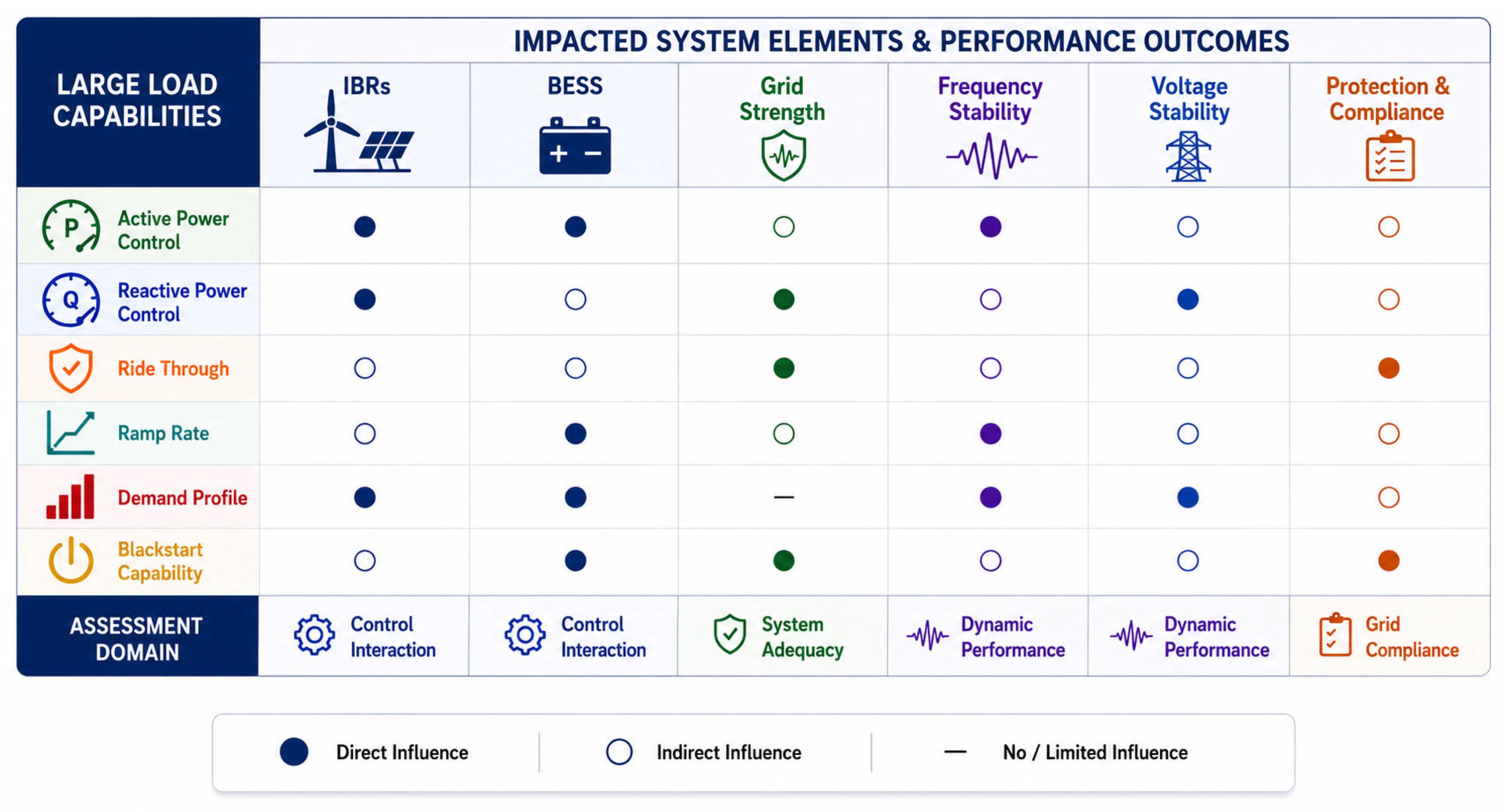
Figure 6 summarizes the principal modeling domains required for representing their interactions with IBRs, ESSs, and transmission networks.
As illustrated in
Figure 6, the proposed framework organizes large-load representation into six interrelated modeling domains: (i) active power and frequency response, (ii) reactive power and voltage regulation, (iii) ride-through and disturbance response, (iv) ramp-rate and power variability management, (v) temporal demand characteristics, and (vi) restoration and black-start behavior. Collectively, these domains capture the primary mechanisms through which modern converter-interfaced loads interact with IBRs, ESSs, and network characteristics. Furthermore, they provide a structured basis for assessing system stability, control interactions, and grid-code compliance across multiple operating timescales.
3.2.1. Active Power and Frequency Regulation
According to the Pacific Northwest National Laboratory, modern loads exhibit controllable behavior through advanced energy management systems, enabling demand flexibility and participation in grid support functions rather than acting as fixed power sinks. From a stability perspective, these loads can adjust consumption in response to grid conditions, introducing additional dynamic interactions [
46].
This behavior can be represented by frequency-dependent active power models analogous to generator droop control, in which load demand decreases as system frequency declines and may be supported by local storage. Such responses can be implemented in simulation tools using P–f droop characteristics with deadband and supervisory control [
46,
47,
48].
Accurate representation of these dynamics is essential for evaluating disturbance performance, as frequency-responsive loads influence metrics such as frequency nadir and the rate of change of frequency (RoCoF), particularly in low-inertia systems with a high penetration of IBRs. The Western Electricity Coordinating Council (WECC) composite load model supports this approach by incorporating frequency-sensitive and dynamic load components, ensuring consistent and validated integration into large-scale stability studies [
49,
50].
3.2.2. Reactive Power and Voltage Regulation
Large electrical loads significantly affect voltage profiles through their capability to absorb or supply reactive power via power electronic converters, induction motors, and filtering systems. Maintaining adequate reactive power support is essential for voltage stability under normal and contingency conditions, and such facilities are typically required to operate within specified power factor limits at the point of interconnection (POI) [
51].
To satisfy these operational requirements, installations employ coordinated voltage-control resources, including capacitor/reactor banks, static VAR compensators, and STATCOMs for fast dynamic support, alongside slower mechanisms such as on-load tap-changer (OLTC) transformers. This establishes a hierarchical control structure spanning fast electronic response and slower mechanical regulation [
51,
52].
In simulation frameworks, these behaviors are represented using Q/V control characteristics, power-factor control loops, or voltage-regulation schemes driven by local measurements. Power electronic interfaces further enhance this capability through programmable Volt–VAR and Volt–Watt functions, enabling fast and flexible voltage support. Hence, the accurate modeling of reactive power behavior is essential for reliable power flow and stability analysis. Meanwhile, neglecting Q/V coupling, control constraints, or interactions with dynamic VAR devices may lead to errors in assessing voltage recovery and to the underestimation of instability risks at the POI [
53].
3.2.3. Ride-Through Capability and Dynamic Response
Fault-induced voltage dips and frequency excursions impose critical stress on both generation and load resources. Emerging large loads, particularly data centers and digital infrastructure, may be highly sensitive to such disturbances due to tightly regulated internal power systems and power electronic interfaces.
Technical assessments indicate that these facilities may disconnect or switch to backup supplies during relatively minor deviations in voltage or frequency. Although intended to protect critical infrastructure, such behavior can aggravate system instability by causing abrupt demand loss, thereby worsening frequency decline and delaying voltage recovery.
Unlike inverter-based generation, which is governed by standards such as IEEE Std 2800-2022 and NERC PRC-024, no unified ride-through requirements currently exist for large loads. This regulatory gap necessitates explicit modeling of voltage- and frequency-dependent response in system studies [
5].
The dynamic representation should include threshold-based disconnection, time-delayed protection, and state-dependent recovery that reflects UPS or backup transitions. These behaviors are implemented in EMT and RMS environments using relay-equivalent logic or state-machine-based composite load models [
54].
Consequently, the accurate inclusion of these mechanisms is essential for a realistic fault-response assessment and to prevent the overestimation of system stability under large-load penetration.
3.2.4. Ramp-Rate Constraints and Power Variability Management
From a physical and operational perspective, ramp-rate constraints limit rapid changes in load demand to mitigate voltage flicker, frequency excursions, and thermal stress on equipment. These limits are particularly important during the restoration and reconnection phases, when uncontrolled load recovery can cause sudden power imbalances and destabilize system frequency and voltage, especially in weak or low-inertia grids [
55].
To address these issues, modern grid codes increasingly impose explicit ramp-rate limits for large loads, defining maximum active power variations over specified time intervals under normal, contingency, and restoration conditions. This ensures coordination between demand transitions and the ramping capability of generation and network infrastructure, effectively treating large loads as controllable dynamic elements within system operation [
56].
From a modeling standpoint, ramp-rate behavior is represented using rate-limiters on active power reference signals, constraining dP/dt to enforce gradual transitions. This approach is implemented in both RMS and EMT simulation tools and is essential to avoid non-physical load steps that distort frequency response and voltage dynamics [
57,
58].
In practice, ramp-rate control operates alongside UPS dynamics, ride-through logic, and operational dispatch constraints, reflecting the integrated control structure of modern large loads. Its inclusion is therefore essential for accurately representing load recovery behavior and for reliably assessing frequency stability, voltage recovery, and system resilience in converter-dominated power systems.
3.2.5. Load Demand Characteristics and Temporal Profiles
The temporal behavior of modern large loads is influenced by both electromechanical processes and digital workload management. In particular, hyperscale data centers exhibit stochastic demand variations associated with computational workload scheduling, cooling requirements, and energy-management strategies. These temporal characteristics define the operating conditions under which fast dynamic phenomena such as frequency response, voltage regulation, and ride-through behavior occur [
59,
60].
Accurate multi-timescale representation of demand profiles is therefore essential for reliable system assessment. Neglecting stochastic and electromechanical variability can distort load diversity, coincidence factors, and aggregate response behavior in large-scale power systems.
3.2.6. Modeling Considerations for Blackstart Capability
Black-start and system restoration require detailed dynamic modeling of large load facilities operating under weak-grid conditions. Accurate representation must capture motor-driven auxiliaries, converter interfaces, transformer energization effects, and load recovery characteristics, as these factors directly influence re-energization paths, voltage recovery, and overall system stability during restoration processes [
61,
62].
EMT modeling is particularly important during black-start studies because it captures fast phenomena such as voltage build-up, frequency synchronization, converter response, and transformer energization. Consequently, a realistic restoration assessment requires the coordinated representation of electromechanical dynamics, power electronic behavior, and staged control actions [
63].
Collectively, the modeling domains discussed throughout this section define the load-side dynamic representation adopted within the proposed control-aware and impedance-informed assessment framework. Accurate characterization of these mechanisms is essential for evaluating source–load interactions, impedance-based stability margins, and compliance with emerging operational and grid-code requirements in converter-dominated power systems.
4. Energy Storage Technologies
4.1. Role of ESS in Large-Load and IBR-Dominated Power Systems
The increasing penetration of inverter-based resources (IBRs) and large transmission-level loads has introduced multi-timescale power imbalances and complex dynamic interactions in modern power systems [
64]. Consequently, energy storage systems (ESSs) have evolved beyond traditional energy-balancing functions to become critical assets for frequency support, voltage regulation, renewable energy integration, ride-through enhancement, and system restoration.
Depending on their operational characteristics, ESS technologies may be broadly categorized into high-energy storage systems for long-duration energy balancing and high-power storage systems for fast dynamic support [
65]. Within the proposed control-aware and impedance-informed assessment framework presented in
Section 2, ESSs form an integral part of the source-side dynamic representation, where their control characteristics and response capabilities directly influence source–load interactions, stability margins, and compliance with dynamic performance requirements.
Accordingly, the following sections review the principal ESS technologies and evaluate their suitability for supporting converter-dominated power systems.
4.2. High-Energy Storage Technologies
These technologies are designed to supply sustained power over extended durations, typically ranging from several minutes to hours or even days. These technologies are fundamentally differentiated by their physical storage mechanisms, ranging from electrochemical to mechanical to thermodynamic. This directly influences their scalability, efficiency, and application domain. These systems are essential for energy arbitrage, peak shaving, load leveling, and renewable energy firming. Their performance is primarily evaluated based on energy density (Wh/kg), lifecycle, safety, and scalability. More details are provided in the following subsections:
4.2.1. Lithium-Ion Battery Energy Storage Systems
Lithium-ion battery energy storage systems (Li-ion BESS) represent the dominant technology for grid-scale applications due to their superior balance between energy density, efficiency, and fast dynamic response. Their operation relies on reversible electrochemical intercalation, where lithium ions migrate between the cathode and anode through an electrolyte under an applied potential difference. This mechanism enables high round-trip efficiency and rapid response, making Li-ion batteries particularly suitable for both steady-state and transient grid support [
66].
From a modeling perspective, the electrical behavior of a Li-ion batteries is commonly described using a nonlinear voltage model as follows:
where the open-circuit voltage
is a nonlinear function of the state of charge (SOC), while
captures transient electrochemical dynamics, such as diffusion and charge-transfer effects, which might be neglected in simpler models. For system-level studies, the Thevenin equivalent circuit model is widely adopted, incorporating an open-circuit voltage source, a series resistance, and one or more RC branches to emulate transient behavior.
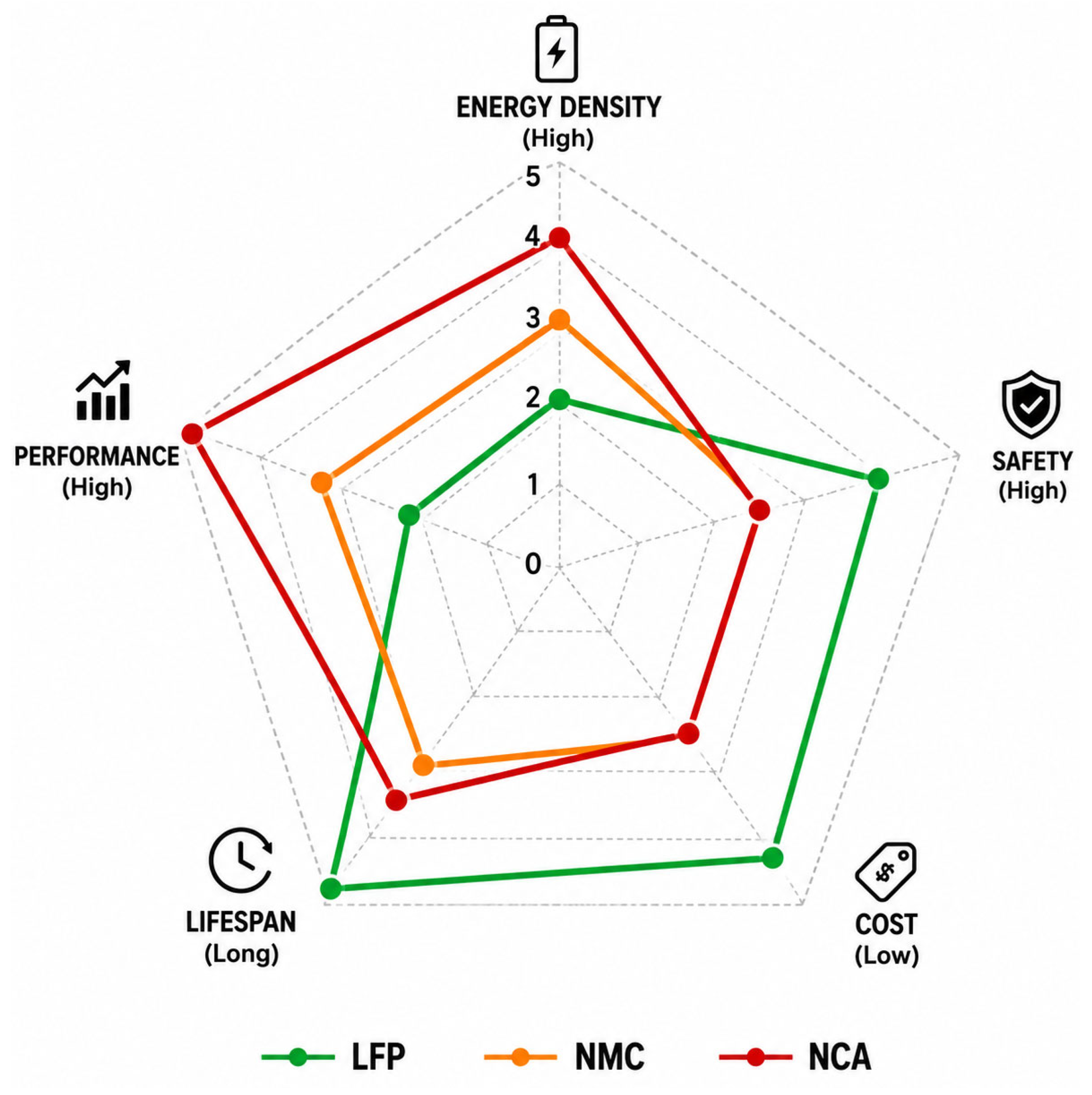
Figure 7 offers a detailed comparison among the three dominant LIBs. Li-ion batteries exhibit high energy density (150–250 Wh/kg), fast response (ms), and high efficiency (90–95%), with a cycle life typically ranging from 3000 to 10,000 cycles depending on chemistry and operating conditions. Among the available chemistries, Lithium Iron Phosphate (LFP) offers enhanced safety and longer lifespan. At the same time, Nickel Manganese Cobalt (NMC) and Nickel Cobalt Aluminum (NCA) provide higher energy density at the expense of thermal stability. Despite these advantages, Li-ion systems face challenges, including thermal runaway risks, degradation due to the growth of the solid electrolyte interphase (SEI), and accelerated aging under high C-rate operation [
66].
4.2.2. Flow Batteries
Flow batteries, particularly vanadium redox flow batteries (VRFBs), store energy in liquid electrolytes, enabling the independent scaling of power and energy capacity. Their long cycle life, deep-discharge capability, and improved safety characteristics make them attractive for long-duration storage applications. However, a lower energy density and increased system complexity remain key limitations compared with lithium-ion batteries [
67,
68].
4.2.3. Pumped Hydro Energy Storage (PHES)
PHES remains the most mature large-scale storage technology, providing gigawatt-hour energy capacity, long operational lifetime, and relatively high efficiency. The PHES stored energy can be expressed as:
where
denotes the stored potential energy (J),
is the water density (kg/m
3),
is the gravitational acceleration (m/s
2),
is the hydraulic head representing the elevation difference between reservoirs (m), and
is the volume of stored water (m
3). Similarly, the instantaneous power output is given by [
62]:
where
represents the generated power (W),
is the overall system efficiency, and
is the volumetric flow rate of water (m
3/s).
Its suitability for bulk energy shifting and peak shaving has led to widespread deployment worldwide. Nevertheless, implementation is limited by geographical and environmental constraints as well as high capital costs [
69,
70,
71].
4.2.4. Compressed Air Energy Storage (CAES)
Compressed Air Energy Storage (CAES) stores energy by compressing air into underground caverns or pressurized vessels during low-demand periods and releasing it to drive turbines during peak demand [
72,
73]. The compression and expansion processes in CAES systems can be interpreted through the following expressions:
where the compression work
represents the total mechanical energy required to compress air,
is the instantaneous air pressure during compression, and
is the differential change in volume. Meanwhile, power generation during expansion follows:
where the generated power
is the mechanical power extracted during air expansion,
is the mass flow rate of the compressed air,
is the specific heat capacity of air at constant pressure,
is the inlet temperature of the expanding air, and
is the outlet temperature after expansion.
CAES technologies are suitable for large-scale and long-duration energy storage applications, typically operating in the hundreds-of-megawatts range. Their primary advantages include large storage capacity and extended discharge duration. However, deployment remains constrained by geological requirements and lower round-trip efficiency compared with electrochemical storage technologies [
72,
73]. A detailed comparison among the high-energy ESS is presented in
Table 4.
4.3. High-Power Storage Technologies
High-power energy storage technologies are specifically engineered to deliver rapid energy exchange over very short time scales, typically ranging from milliseconds to a few seconds. These systems play a pivotal role in modern power systems, supporting frequency regulation, transient stability enhancement, voltage control, and mitigation of power quality disturbances. Unlike high-energy storage technologies, whose primary design objective is bulk energy delivery, these technologies prioritize high ramp rates, fast dynamic response, and frequent cycling.
4.3.1. Supercapacitors (SC)
Supercapacitors, also referred to as ultracapacitors, store energy through electrostatic charge separation at the electrode–electrolyte interface, forming an electric double layer. The stored energy can be expressed as:
where
is the stored energy,
is the capacitance, and
is the terminal voltage. Their electrical behavior is commonly represented using an impedance-based model, as in:
where
is the frequency-dependent impedance,
is the equivalent series resistance, and
is the angular frequency.
From a performance perspective, SCs exhibit extremely high-power density and ultra-fast charge/discharge dynamics, governed by small RC time constants. Furthermore, their cycle life exceeds one million cycles, making them highly suitable for applications involving repetitive high-frequency operation. However, their energy density remains relatively low, which limits their use to short-duration applications [
64,
65].
In practical applications, supercapacitors have been widely deployed in transportation systems, particularly in metro and light rail networks, where they capture regenerative braking energy and re-inject it during acceleration phases. Despite their advantages, key limitations include limited energy storage capacity and challenges associated with voltage balancing in series-connected modules [
65].
4.3.2. Flywheel Energy Storage Systems (FESS)
Flywheel energy storage systems store energy as rotational kinetic energy in a high-speed rotor. The stored energy is given by [
73]:
where
is the moment of inertia and
is the angular velocity.
FESS are characterized by high round-trip efficiency, rapid response times, and long cycle life, often exceeding 100,000 cycles. Their operation is enabled by advanced power electronic converters that regulate rotor speed and facilitate bidirectional energy exchange with the grid, enabling precise, fast active power control. These attributes, combined with high power density and mechanical robustness, make FESS particularly suitable for applications requiring frequent cycling, high reliability, and fast dynamic support, such as frequency regulation and transient stability enhancement. However, despite these advantages, FESS are subject to relatively high self-discharge losses due to frictional and aerodynamic effects, even when operating under near-vacuum conditions. In addition, they require robust mechanical containment structures to ensure safe operation at high rotational speeds, thereby increasing system complexity and capital costs [
73,
74,
75].
4.3.3. Superconducting Magnetic Energy Storage (SMES)
Superconducting magnetic energy storage systems store energy directly in the magnetic field generated by a direct current flowing through a superconducting coil. With coil inductance
and the circuit current
, the SMES stored energy can be expressed as [
76]:
SMES systems provide near-instantaneous response and very high efficiency, making them attractive for fast grid-support applications. However, high capital costs and cryogenic cooling requirements continue to limit their widespread deployment [
77,
78].
Table 5 compares the principal characteristics of high-power storage technologies used for fast dynamic support in converter-dominated power systems.
4.4. Hybrid Energy Storage Systems (HESS)
Hybrid energy storage systems (HESS) integrate complementary storage technologies to simultaneously achieve high energy and high-power densities, thereby overcoming the inherent limitations of individual systems. For instance, fast-response devices such as supercapacitors (SCs) or flywheels (FESS) are typically combined with BESS to enhance transient performance, extend battery lifetime, and improve overall system efficiency according to the following equation [
20,
64]:
where
is the total power is exchanged with the grid,
and
represent the power supplied from the high-energy and high-power storage components, respectively. In this configuration, the high-power device is responsible for handling rapid power fluctuations, transient spikes, and high-frequency components, while the battery, as a
, manages the low-frequency and steady-state energy demand.
Common HESS configurations include battery–supercapacitor [
64], battery–flywheel [
79], and battery–flow battery systems, which improve dynamic performance, extend battery lifetime, and enhance operational flexibility across multiple timescales. However, these benefits are achieved at the expense of increased control complexity and system integration requirements [
80,
81].
Table 6 summarizes the principal HESS configurations and their characteristics.
4.5. Functional Mapping of ESS Technologies to Grid Support Services
Table 7 maps major ESS technologies to the grid-support services most relevant to converter-dominated power systems.
As illustrated in
Table 7, ESS technologies contribute to grid operation through complementary dynamic mechanisms and operating timescales. Within the proposed control-aware and impedance-informed assessment framework, these technologies collectively define the energy storage representation incorporated within the source-side subsystem. Consequently, their response characteristics and support capabilities directly influence source–load interactions, stability margins, and compliance with dynamic performance requirements.
5. Technical Requirements and Grid Code Compliance
The growing penetration of IBRs, BESS, and hyper-scale loads has fundamentally altered power system behavior, requiring revised technical requirements and updated grid codes. In contrast to synchronous machines, power electronic-interfaced resources provide limited fault current, rapid control-driven responses, and reduced inherent inertia, which complicate traditional protection, planning, and operational practices.
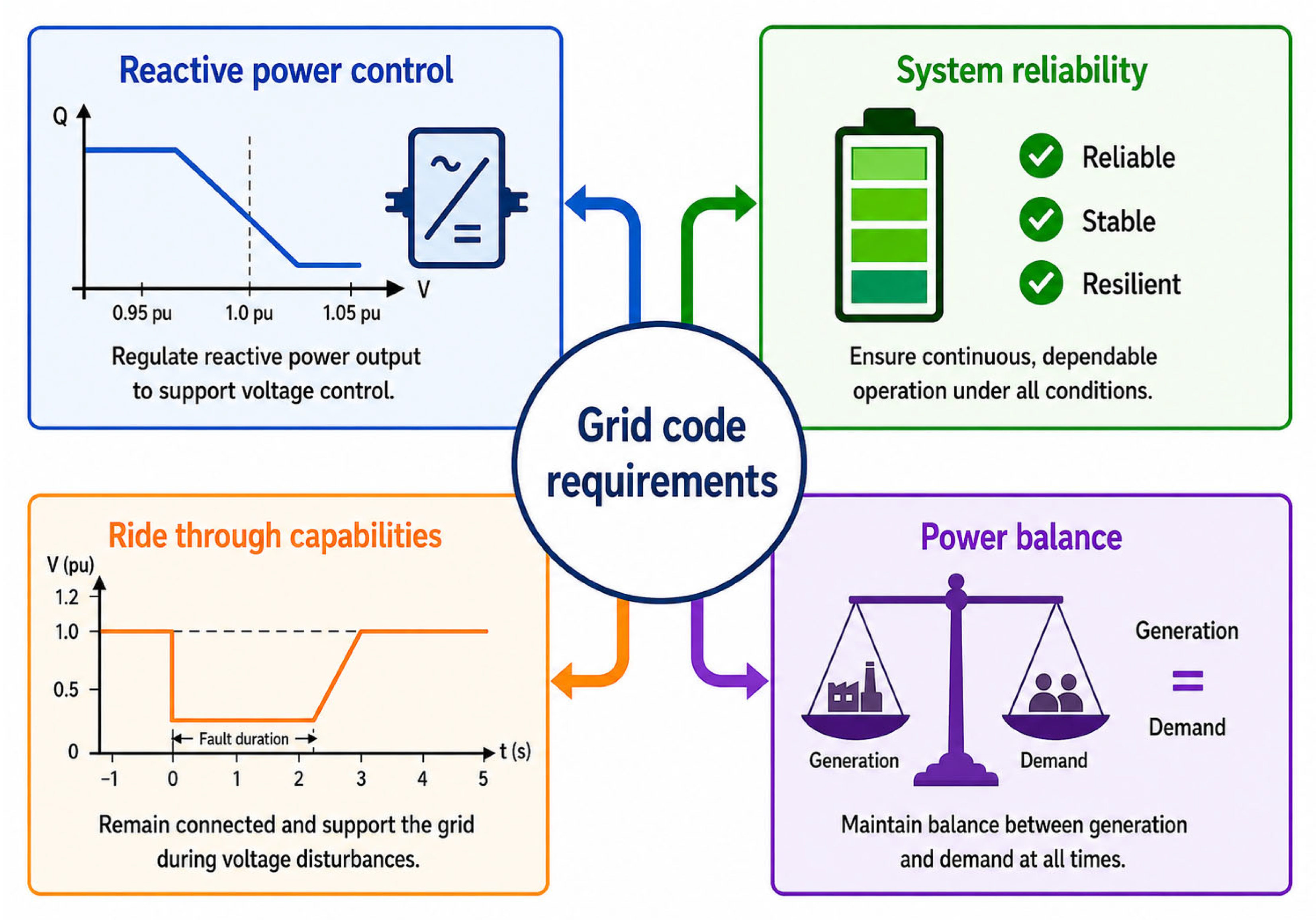
Grid codes define minimum performance standards for connected assets and have been progressively updated to address converter-dominated systems. Key requirements shown in
Figure 8 emphasize fault ride-through capability, voltage and frequency support, and enhanced system strength through advanced inverter functions, including grid-forming control. Moreover, the role of BESS has expanded beyond ancillary services to include active participation in fault response and operation under weak- grid conditions, requiring coordinated compliance with steady-state and dynamic performance requirements [
82].
From the perspective of the proposed control-aware and impedance-informed assessment framework introduced in
Section 2, grid codes constitute the final compliance layer through which the technical adequacy of large-load models, energy storage systems, inverter-based resources, and system-strength assessment methodologies is ultimately evaluated. While the preceding sections focused on the dynamic representation of these components and their interactions, the present section examines the performance requirements that determine whether such behavior is acceptable from planning, operational, and reliability perspectives. Accordingly, this section outlines the core requirements for IBR and BESS integration, including interconnection standards, fault ride-through criteria, system-strength considerations, and protection coordination challenges in low-inertia networks. These requirements serve as the principal compliance benchmarks used throughout the proposed framework to evaluate dynamic performance, stability margins, and operational robustness under converter-dominated operating conditions.
5.1. Grid Codes and Interconnection Standards
Within the proposed assessment framework, interconnection standards represent the first layer of compliance evaluation because they define the minimum technical and operational requirements that connected resources must satisfy before detailed dynamic performance assessment can be performed.
This section reviews key standards in the United States, Europe, and international frameworks, focusing on interconnection requirements and dynamic performance criteria. It also outlines major similarities and differences among these standards.
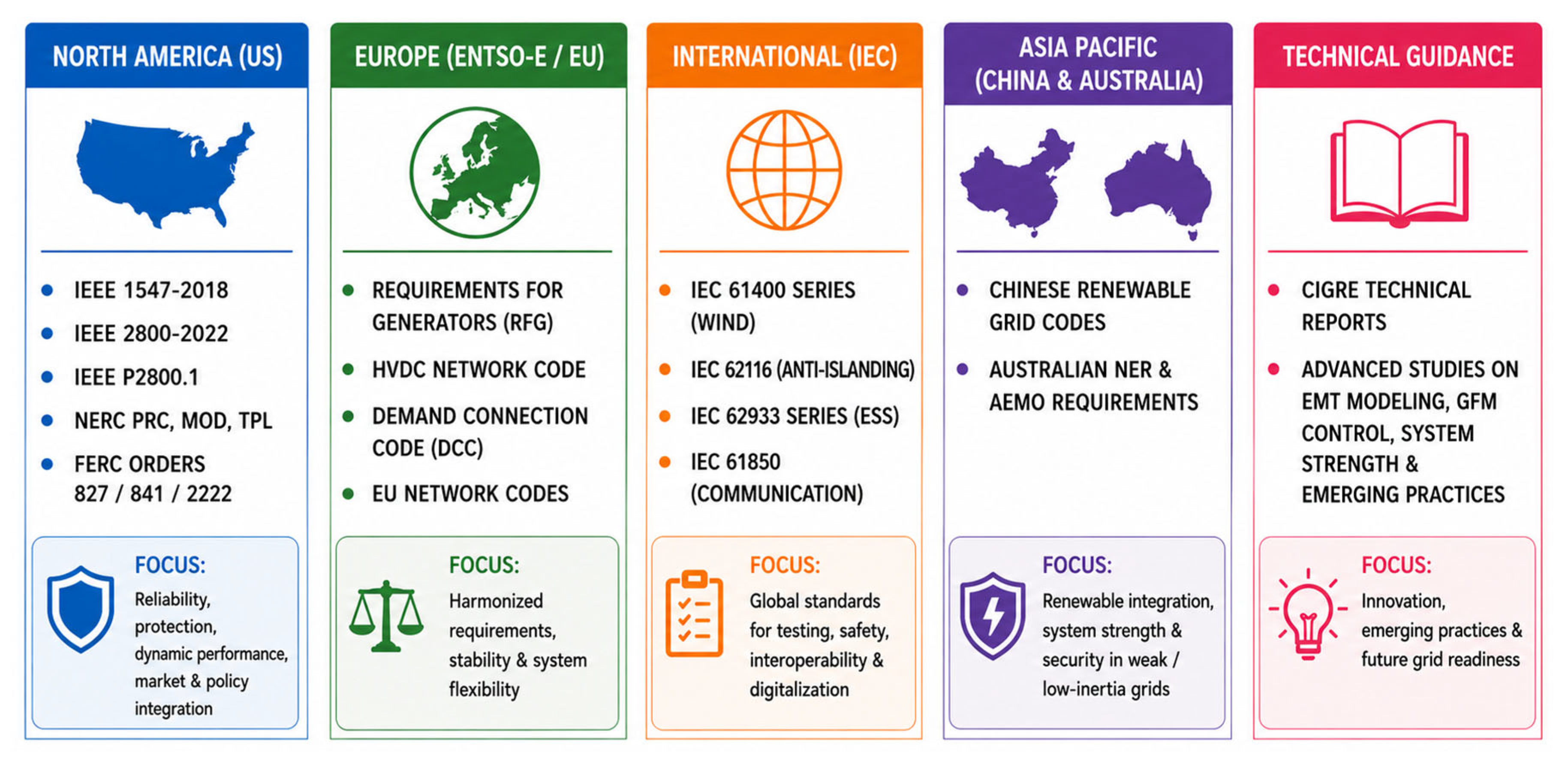
Figure 9 shows the key global standards that enable the reliable, secure, and efficient integration of generators and IBRs.
5.1.1. United States Framework: Layered Standards and Regulatory Integration
In the United States, IBR interconnection requirements are governed by a multi-layered framework combining IEEE technical standards, NERC reliability standards, and FERC regulatory orders [
82,
83].
At the distribution level, IEEE 1547-2018 defines requirements for distributed energy resources, including voltage regulation, frequency response, and ride-through capability, marking a shift from passive disconnection to active grid support. At the transmission level, IEEE 2800-2022 extends these requirements to bulk system resources, specifying fault ride-through, reactive current injection, and enhanced active/reactive power control [
83,
84,
85,
86].
Complementary NERC standards (TPL, PRC, and MOD families) govern planning adequacy, protection performance, and model validation, while PRC-024 defines ride-through envelopes and MOD-026/027 ensure model accuracy against field data. FERC Orders 827, 841, and 2222 further enable storage and aggregated DER participation in wholesale markets, indirectly shaping technical requirements through operational flexibility and grid service provision [
87,
88,
89,
90].
5.1.2. European Framework: Harmonized and Binding Grid Codes
In contrast to the U.S. approach, Europe adopts a centrally coordinated and legally binding framework through the European Network of Transmission System Operators for Electricity (ENTSO-E) network codes. The Requirements for Generators (RfG) code is the primary document governing IBR integration, categorizes generators by capacity and voltage level, and specifies detailed technical requirements for each category.
The RfG code mandates fault ride-through capability, frequency response with active power control, and reactive power provision across specified voltage ranges. Complementary codes include the HVDC framework for converter-dominated systems and the Demand Connection Code for flexible demand participation [
91,
92,
93].
A defining feature of the European framework is its emphasis on future grid-forming operation, particularly as system inertia declines, with increasing requirements for voltage support, frequency stability, and synthetic inertia provision from large-scale IBRs [
94].
5.1.3. International Standards: IEC and Technical Harmonization
At the international level, inverter-based resource (IBR) integration is guided by International Electrotechnical Commission (IEC) standards and national grid codes, forming a semi-harmonized framework. Unlike the structured regulatory systems in the United States and Europe, this approach is primarily equipment-focused, where IEC standards define testing and certification requirements, while countries translate them into system-level rules.
Key standards include IEC 61400 for wind turbine systems [
29], IEC 62933 for energy storage systems [
95], and IEC 62116 for anti-islanding performance evaluation. These establish procedures for performance verification [
96], including fault ride-through testing, dynamic response evaluation, and protection validation [
97], rather than prescribing grid operation requirements. As a result, IEC standards serve as a global technical baseline, enabling interoperability across jurisdictions while allowing flexibility for local grid-code adaptation [
98,
99].
Building upon this foundation, national frameworks extend these principles differently. China, through the National Energy Administration and the State Grid Corporation of China, enforces strict fault-ride-through and reactive-current-support requirements, emphasizing the centralized dispatchability of IBRs [
100,
101,
102]. In contrast, Australia, under the Australian Energy Market Operator (AEMO), applies performance-based requirements tailored to weak-grid conditions, including EMT-based studies, fast frequency response, synthetic inertia, and advanced system-strength assessment [
103].
Across these international frameworks, several common technical themes can be identified. First, there is a strong emphasis on fault ride-through capability and dynamic voltage support, which are essential for maintaining system stability during disturbances. Second, the role of accurate modeling and validation, including EMT simulations, is becoming increasingly important, especially in systems with high IBR penetration. Third, anti-islanding requirements remain a fundamental aspect of interconnection standards, although their implementation is evolving in response to new operational paradigms such as grid-forming control and microgrids.
Despite these convergences, implementation differs significantly. IEC standards provide testing consistency without enforcing operational compliance; China adopts a centralized, prescriptive model; and Australia relies on detailed system studies and performance-based criteria. These differences reflect variations in grid strength, topology, and generation mix.
Overall, international IBR integration can be viewed as a layered structure in which IEC standards ensure global consistency at the equipment level, while national codes define system-specific operational requirements. This dual structure supports renewable integration while accommodating regional system constraints.
Table 8 summarizes the international standards and grid codes for interconnection requirements [
82,
83,
84,
85,
86,
87,
88,
89,
90,
91,
92,
93,
94,
95,
96,
97,
98,
99,
100,
101,
102,
103,
104,
105,
106].
Collectively, these standards establish the compliance requirements against which the dynamic behavior of large loads, energy storage systems, and inverter-based resources must be evaluated. Within the proposed framework, they provide the regulatory basis for assessing ride-through performance, system-strength adequacy, protection coordination, and EMT validation results discussed in the following subsections.
5.2. Fault Ride-Through (FRT) Requirements
Within the proposed framework, ride-through performance represents one of the primary validation criteria used to determine whether the dynamic interactions identified through stability assessment remain acceptable during severe disturbances.
Fault ride-through (FRT) capability is a fundamental requirement for IBRs and BESS to maintain grid stability during disturbances. It defines the ability of these resources to remain connected and operate within specified limits under short-term voltage and frequency deviations. With increasing penetration of converter-interfaced technologies and reduced system inertia, modern grid codes mandate explicit voltage and frequency ride-through profiles to prevent disconnection during faults.
In this context, voltage ride-through (VRT) requirements define the minimum time that IBRs must remain connected during voltage disturbances, including low-voltage ride-through (LVRT) and high-voltage ride-through (HVRT). LVRT is critical during short-circuit faults when the POI voltage may collapse. Grid codes typically specify a voltage–time profile that requires sustained operation during deep voltage dips, followed by controlled recovery [
107,
108]. During this period, IBRs must inject reactive current proportional to voltage deviation to support system recovery, expressed as:
where
is the reactive current injection,
is the voltage-support gain, and
and
represent the reference and measured voltages, respectively.
In contrast, HVRT ensures continued operation during temporary overvoltage conditions due to load rejection or switching events, preventing unnecessary tripping and cascading outages.
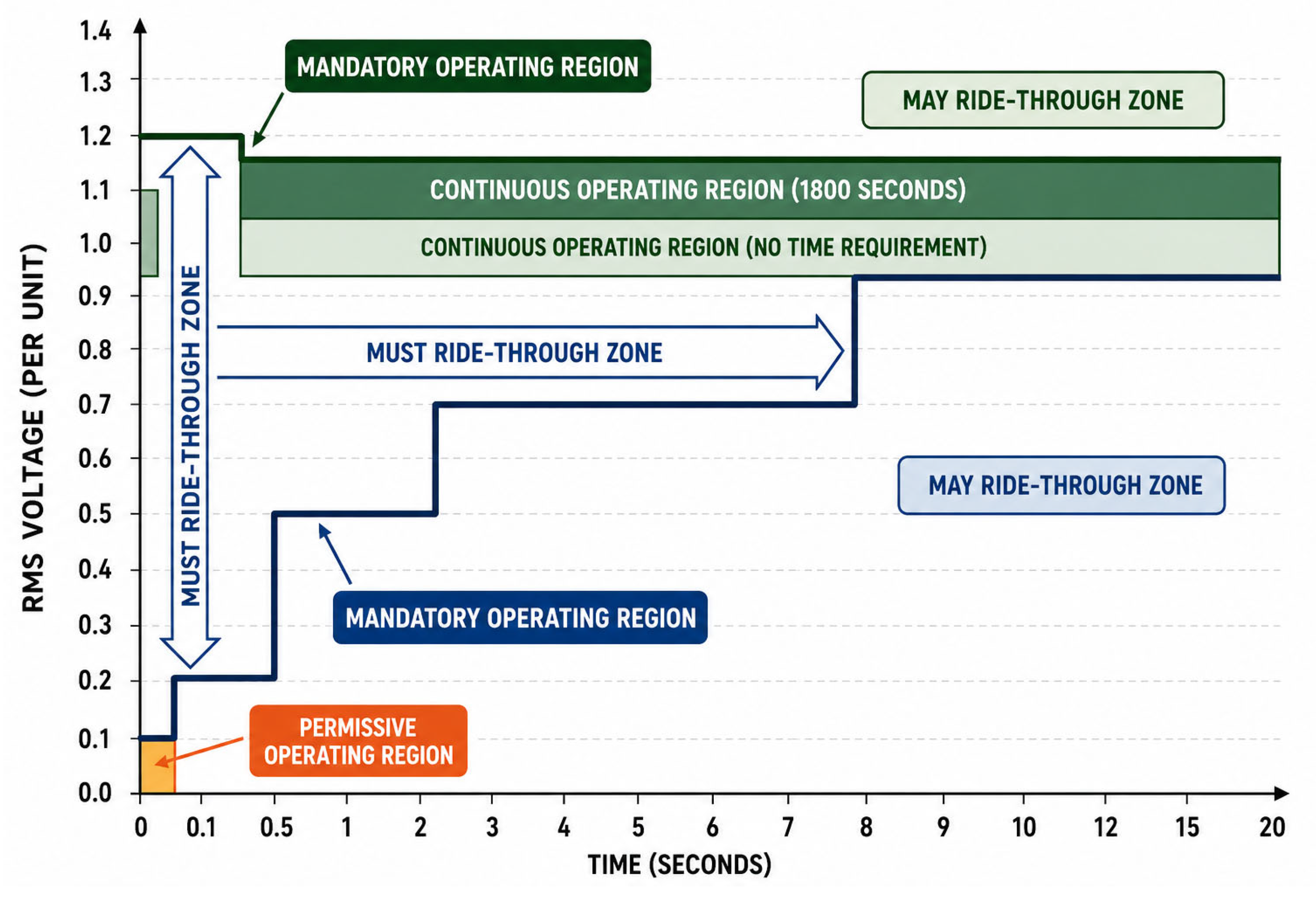
Figure 10 shows the voltage ride-through operating regions defined by NERC under PRC-029-1.
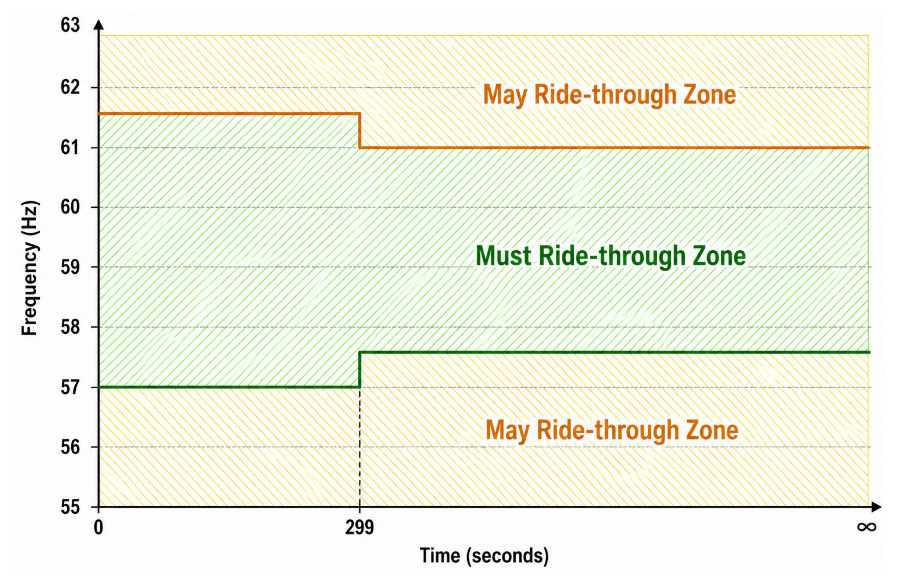
Within the same framework, set operational limits under deviations from nominal frequency, covering low-frequency (LFRT) and high-frequency (HFRT) conditions. LFRT maintains connection during generation deficits, while HFRT addresses surplus generation, ensuring system adequacy and preventing cascading outages [
109]. Grid codes specify frequency–time envelopes as shown in
Figure 11. Additionally, advanced IBRs may be required to provide active power-frequency support through droop control mechanisms, expressed as:
where
is the change in active power output,
is the frequency droop coefficient, and
and
are measured and nominal frequencies, respectively. This dynamic response contributes to frequency stabilization by adjusting power output in proportion to frequency deviations.
Integrating voltage and frequency ride-through requirements introduces key control challenges, including prioritizing fault-current injection, ensuring converter stability during severe disturbances, and coordinating with protection systems. Phase-locked loop (PLL) instability during deep voltage sags can disrupt synchronization, motivating the use of grid-forming control or improved synchronization methods. In addition, improper coordination with protection schemes may interfere with fault clearing and reduce system reliability [
110].
Current grid code evolution shifts ride-through requirements from passive operation to active system support, requiring IBRs and BESS to contribute to voltage and frequency recovery through fast reactive current injections, voltage regulation, and frequency response. This transition, particularly under weak-grid and high-penetration conditions, necessitates robust control design, accurate modeling, and rigorous validation of converter interactions.
Recent grid-code developments increasingly recognize the role of grid-forming operation in enhancing system strength, voltage recovery, and fault response under weak-grid conditions. Consequently, there is growing interest in performance-based requirements that distinguish between grid-following and grid-forming capabilities, particularly with respect to fault ride-through performance, voltage support, and post-disturbance system recovery.
5.3. Short-Circuit Contribution and System Strength
From the perspective of the proposed assessment framework, system-strength evaluation provides the analytical bridge between component-level dynamic models and compliance-oriented performance requirements. Consequently, system-strength assessment plays a central role in determining stability margins, control interactions, and acceptable operating conditions for converter-dominated systems.
Short-circuit contribution is a key indicator of system strength, particularly in grids with high penetration of IBRs and storage systems. Unlike synchronous generators, which typically supply 4–6 p.u. fault current, IBRs are converter-limited and generally restricted to 1.1–1.3 p.u. for short durations, reducing overall fault current availability and affecting protection sensitivity and voltage recovery. As a result, grid codes now specify minimum requirements for fault current injection and system-strength requirements [
111].
System strength is commonly quantified using the SCR, defined as in the following equation:
where
is the short-circuit capacity at the POI and
is the rated capacity of the IBR or plant. Power systems with SCR values above 3 indicate strong grids; 2–3 indicate weak conditions; and below 2 indicate very weak systems, where voltage stability, synchronization, and control interactions become increasingly constrained. Accordingly, standards such as IEEE Std 2800-2022 and ENTSO-E require IBRs to maintain stable operation under low-SCR conditions down to approximately 1.5–2 in advanced cases [
26,
111].
Furthermore, grid codes mandate fast reactive current injection during faults to compensate for reduced short-circuit strength. For instance, IEEE Std 2800-2022 requires proportional reactive current support within 20–40 ms of fault detection, while system operators such as National Grid ESO and AEMO specify high-gain voltage-dependent current injection (≈2–6 p.u.) to support voltage recovery and transient stability.
Additionally, to maintain system adequacy, operators impose minimum short-circuit thresholds or require additional support devices such as STATCOM and synchronous condensers. These constraints have driven increased adoption of grid-forming control and advanced inverter designs capable of providing virtual inertia and robust fault response under low-SCR conditions.
When multiple IBRs are connected at different POIs, short-circuit capacity is shared across the network, leading to an overestimation of system strength when using conventional SCR. To address this, a weighted short-circuit ratio (WSCR) is applied as follows [
111]:
where
denotes the total number of POIs,
is the short-circuit capacity in MVA at the
POI,
is the IBR real power rating. Although WSCR better reflects aggregated system conditions, it remains conservative and provides limited insight into detailed dynamic behavior.
On the other hand, reduced fault current levels also introduce protection challenges, as conventional overcurrent schemes may become unreliable. This necessitates advanced methods such as differential, distance, and traveling-wave protection, often supported by EMT validation to ensure accurate fault representation and relay coordination.
5.4. Beyond SCR: Multi-Metric Assessment of System Strength
Generally, SCR is widely used as a first-order indicator of grid strength; however, its applicability in inverter-dominated systems is limited. It represents only fundamental-frequency impedance and does not capture frequency-dependent interactions between IBRs and the network. Consequently, instability or oscillations may occur even at high SCR values due to interactions between control and harmonic frequencies. Moreover, SCR neglects key operational factors, such as voltage variations, tap-changer actions, and the influence of grid-support devices like STATCOMs and synchronous condensers, which significantly affect system strength but are not reflected in SCR calculations. Alternative indices, such as voltage sensitivity (∂Q/∂|V|), provide improved local insight into voltage stability but remain limited to single-POI representations and do not capture multi-frequency dynamics [
112].
While SCR remains the most widely adopted system-strength metric, practical assessment of converter-dominated power systems increasingly requires the use of multiple complementary indicators rather than reliance on a single index. Different metrics provide different perspectives on system behavior and therefore should be viewed as components of a hierarchical assessment process rather than competing alternatives.
For preliminary planning and interconnection studies, SCR continues to provide a useful first-order screening indicator because of its simplicity and widespread industry adoption. When multiple converter-based resources are electrically coupled within the same region, WSCR offers a more representative assessment of aggregated system conditions. Similarly, voltage-sensitivity indices provide additional information regarding reactive power adequacy and local voltage-stability margins.
However, as converter penetration increases and control interactions become more significant, assessment must progressively transition toward dynamic indicators capable of capturing frequency-dependent phenomena. In such cases, impedance-based analysis and Nyquist-based stability margins provide substantially greater insight because they explicitly account for converter controls, network characteristics, and source–load interactions [
27,
28].
Accordingly, the proposed control-aware and impedance-informed assessment framework introduced in
Section 2 adopts a staged evaluation philosophy. Conventional short-circuit-based metrics are used for preliminary screening and planning studies, whereas impedance-based techniques and EMT validation are employed whenever weak-grid conditions, reduced stability margins, or significant converter interactions are identified. This layered approach enables practical planning decisions while maintaining sufficient modeling fidelity for detailed stability assessment [
27,
28,
30,
31].
The metrics summarized in
Table 9 represent successive assessment layers within the proposed framework. Detailed formulation of impedance-based metrics is presented in the following subsection.
5.5. Impedance-Based Stability Assessment
To address these limitations, impedance-based analysis offers a more comprehensive framework by modeling the frequency-dependent interaction between the network and converters. It represents system behavior using impedance/admittance models derived from EMT simulations or measurements, often through dq-domain perturbation and frequency scanning techniques that construct the system impedance matrix for stability assessment across a wide frequency range, as in the following equation [
28,
30,
111]:
where
and
represent the impedances in the d- and q-axis, respectively; and
and
represent the cross-coupling impedances between both axes;
,
and
,
are the d-q voltages and currents measured during perturbation 1; and
,
and
,
are the d-q voltages and currents measured during perturbation 2.
This matrix captures coupling between dq axes and the impact of control loops, including PLLs, current controllers, and outer regulation layers, under both grid-following and grid-forming operation [
28,
30]. It reflects combined electrical and control dynamics across multiple time scales, enabling identification of resonances and stability margins using criteria such as the Nyquist stability theorem [
27]. Consequently, the impedance characteristics associated with GFL and GFM converters may differ significantly, resulting in distinct stability margins, resonance behavior, and weak-grid performance characteristics [
29]. Accordingly, impedance-based analysis provides a physically consistent and robust framework for stability assessment in low-inertia, converter-dominated power systems [
27,
28,
30].
Table 10 summarizes the existing techniques for assessing grid strength.
The system-strength assessment methodologies discussed above provide the analytical foundation for understanding fault-current behavior and converter-network interactions. These characteristics directly influence protection performance and therefore motivate the adaptive protection strategies discussed in the following subsection.
5.6. Protection Coordination in Low-Inertia Systems
Protection coordination in low-inertia systems has become more complex due to the widespread integration of IBRs and BESS. Unlike synchronous machines, IBRs provide limited, controlled fault current due to semiconductor constraints, reducing the effectiveness of conventional overcurrent- and distance-based protection. In weak grids (SCR < 3), fault current levels may approach load current, leading to protection blinding and delayed relay operation [
113].
To address this, modern standards promote adaptive and communication-assisted schemes. For instance, IEC 61850 enables fast peer-to-peer exchange for differential protection with sub-10 ms latency, while differential protection is increasingly adopted as a primary scheme due to its insensitivity to fault current magnitude. However, such communication-based approaches introduce cybersecurity considerations. IEEE Std 2800-2022 further requires IBRs to remain operational during deep voltage depressions, which alter fault signatures and complicate relay coordination. As a result, impedance-based and traveling-wave protection methods are gaining importance, alongside dynamic distance protection settings informed by real-time system-strength indicators such as SCR [
114].
To improve observability, wide-area measurement systems using phasor measurement units (PMUs) are increasingly deployed, enabling coordinated fault detection under fast-changing inverter-dominated conditions.
5.7. Compliance with IEEE, NERC, and Regional Standards
The requirements discussed throughout the previous subsections collectively converge in the compliance assessment process. Therefore, this subsection summarizes how different regulatory organizations translate technical performance expectations into enforceable interconnection and reliability requirements.
Compliance with technical standards and reliability codes is essential for integrating IBRs and BESS into modern, low-inertia power systems. Regulatory frameworks have shifted from static interconnection rules to performance-based requirements that address dynamic behavior during disturbances. This compliance structure is coordinated through IEEE, NERC, and IEC, ensuring stability, protection coordination, and system support capabilities.
At the system operation level, regional system operators translate these standards into grid-specific requirements. In North America, WECC and PJM rely on detailed interconnection studies and EMT-based validation, particularly under weak-grid conditions. In Australia, AEMO enforces system-wide requirements tailored to high renewable penetration and low inertia. In China, the State Grid Corporation applies centralized dispatch and strict interconnection rules, whereas in Europe, requirements are coordinated through ENTSO-E within a harmonized framework.
Collectively, these institutions form a layered compliance hierarchy in which IEEE defines technical expectations, NERC enforces reliability, IEC provides testing standards, and regional operators adapt requirements to local grid conditions, ensuring secure operation of inverter-dominated power systems [
115].
6. Challenges, Research Gaps, and Emerging Directions
The transition toward inverter-based, low-inertia power systems introduces a set of interdependent technical challenges that span modeling, stability assessment, protection, and operational coordination. While significant progress has been achieved in defining grid codes and interconnection standards, several critical gaps remain in accurately representing the dynamic behavior of modern large-scale loads, IBRs, and BESS under real operating conditions.
These challenges are not isolated issues; rather, they emerge from the coupled interactions among large electronic loads, energy storage systems, inverter-based resources, and network characteristics highlighted in the control-aware and impedance-informed framework introduced earlier. Consequently, addressing these gaps requires integrated approaches that simultaneously consider control dynamics, system strength, protection behavior, and operational coordination across multiple timescales.
6.1. Key Technical Challenges
A primary challenge lies in the reduced physical inertia and limited fault-current contribution of IBRs, which fundamentally alter the traditional assumptions used in protection and stability studies. Conventional SCR-based metrics and positive-sequence models are no longer sufficient to capture frequency-dependent interactions, control-driven dynamics, and multi-timescale behavior. This limitation becomes more pronounced under weak-grid conditions, where control interactions, PLL instability, and impedance coupling can trigger unexpected oscillations even within nominal stability margins.
An additional challenge is the coordination of control actions across multiple timescales. Fast converter controls, ESS dispatch, demand response, protection functions, and restoration procedures often operate with different objectives and time constants. In converter-dominated systems, inadequate coordination among these layers can lead to control conflicts, oscillatory behavior, or suboptimal system performance, particularly in networks with high concentrations of large electronic loads and storage resources.
Protection coordination also faces increasing complexity due to low and controlled fault current levels. Traditional overcurrent-based schemes are progressively being replaced by communication-assisted and differential protection methods; however, these introduce new dependencies on cyber-physical reliability and latency constraints. In parallel, EMT-based validation requirements significantly increase the computational burden for system-level studies, particularly for large-scale interconnection assessments.
Another key challenge is the lack of unified modeling frameworks for large dynamic loads. Emerging load behaviors—such as stochastic demand variability, ride-through-controlled disconnection, and grid-interactive operation—are not consistently represented across simulation platforms. This inconsistency limits the accuracy of planning studies and reduces confidence in stability margins, particularly for high-density load clusters such as data centers and electrified industrial facilities.
6.2. Research Gaps
Despite advances in grid codes and modeling practices, several gaps remain. First, current system-strength metrics, including SCR and weighted SCR formulations, provide limited insight into frequency-dependent stability phenomena and multi-POI interactions. Second, there is no universally adopted modeling standard that integrates electromechanical loads, converter dynamics, and control interactions within a unified framework. Third, ride-through requirements are still predominantly defined as minimum survival criteria rather than active support functions in many jurisdictions. This creates inconsistency in how IBRs and large loads contribute to system restoration and transient stability.
Another important gap is the limited availability of scalable EMT–RMS co-simulation frameworks that can simultaneously capture detailed converter behavior and large-system dynamics. Existing approaches often face trade-offs between model fidelity, computational cost, and interoperability across software platforms. Finally, protection models often remain decoupled from dynamic system studies, limiting the ability to evaluate fault behavior under realistic converter-controlled conditions.
6.3. Future Trends and Emerging Directions
Future power systems are expected to rely increasingly on grid-forming converters, battery energy storage systems (BESSs), and inverter-based resources to provide essential reliability services, including synthetic inertia, voltage support, and frequency regulation, particularly in weak-grid environments with high penetrations of renewable generation and large electronic loads. This transition is driving the evolution of stability assessment methodologies from conventional synchronous-machine-based approaches toward dynamic, control-oriented frameworks. While short-circuit-ratio metrics remain widely used, impedance-based stability analysis and adaptive system-strength assessment methods are gaining importance because they better capture converter interactions, frequency-dependent behavior, and changing network conditions in real time.
In parallel, hybrid physics-informed and data-driven modeling approaches are emerging to improve the representation of inverter dynamics, load uncertainty, and evolving operating conditions. Artificial intelligence is also expected to play an increasing role in coordinating energy storage dispatch, large-load flexibility, and inverter-based resource controls to enhance system stability and operational performance. Meanwhile, protection systems are evolving toward resilient cyber-physical architectures capable of maintaining secure operation under communication disturbances, synchronization errors, and cybersecurity threats. Regulatory frameworks and grid codes are similarly shifting from passive interconnection requirements toward active system-support obligations, requiring coordinated participation from generation, storage, and controllable loads through advanced ride-through capabilities, fast frequency response, and dynamic reactive power support. Together, these developments highlight the need for integrated advances in modeling, system-strength assessment, protection, operational control, and regulatory standards to ensure the reliable and resilient operation of converter-dominated power systems.
7. Conclusions
The transition toward converter-dominated power systems is exposing fundamental limitations in conventional approaches for system-strength assessment, stability evaluation, and grid-code compliance. In particular, the increasing interactions among inverter-based resources, energy storage systems, and large power electronic loads require analytical methodologies that extend beyond traditional SCR-based and steady-state representations.
A central observation emerging from this review is that large transmission-level loads, inverter-based resources, and energy storage systems can no longer be evaluated as independent components. Their behavior is increasingly governed by coupled control interactions that directly influence system strength, stability margins, protection performance, and grid-code compliance. Consequently, future planning and operational methodologies must adopt integrated source–load perspectives capable of capturing these interactions across multiple timescales.
This review demonstrates that future power-system assessment must increasingly account for control-driven and frequency-dependent interactions. Accordingly, a key contribution of this work is the development of a unified control-aware and impedance-informed assessment framework that provides a common analytical structure for representing network dynamics, converter controls, large-load behavior, and energy storage response. By integrating source–load interaction analysis, impedance-based stability assessment, and EMT-oriented validation within a hierarchical evaluation methodology, the framework establishes a systematic link between planning-level studies and high-fidelity dynamic assessment.
The review further highlights that system strength should be viewed as a multi-dimensional concept rather than a single SCR-based metric. Consequently, a hierarchical assessment philosophy combining conventional system-strength indicators, impedance-based techniques, Nyquist-based stability evaluation, and EMT validation is proposed to support future converter-dominated power systems.
Overall, the proposed framework provides a unified perspective for evaluating the coupled interactions among large loads, inverter-based resources, energy storage systems, and grid-code requirements. By linking component-level dynamic behavior with system-level stability assessment and compliance evaluation, the framework offers a practical foundation for future research, interconnection studies, and operational planning in low-inertia power systems.