Article

Adaptive Virtual Inertia Control for Two-Stage Grid-Forming PV Inverter Considering DC-Link Dynamics

State Grid Jiangsu Electric Power Company Ltd. Research Institute, Nanjing 211103, China
*
Author to whom correspondence should be addressed.
Electronics 2026, 15(12), 2667; https://doi.org/10.3390/electronics15122667
Submission received: 29 April 2026 / Revised: 31 May 2026 / Accepted: 11 June 2026 / Published: 16 June 2026
(This article belongs to the Special Issue Intelligent Control Strategies for Power Electronics)

Abstract

Two-stage grid-forming (GFM) photovoltaic inverters leverage the dynamic characteristics of the DC-bus capacitor to emulate the inertia of synchronous generators. However, under conditions of drastic solar irradiance fluctuations or sudden increases in grid load, fixed virtual inertia parameters struggle to simultaneously ensure both effective grid frequency support and stable DC-bus voltage, often leading to DC voltage dips or even system disconnection. To address this issue, this paper proposes an adaptive virtual inertia control strategy that takes into account the dynamic resources on the DC side. First, based on the dynamics of the DC-bus voltage, the synchronous equations for the inverter are derived, and a quantitative mapping relationship between the control parameters and the virtual inertia, as well as the damping coefficient, is established. Second, an inertia control law that adaptively adjusts according to the photovoltaic output power is designed. When solar irradiance is abundant, the virtual inertia is increased to provide sufficient frequency support, and vice versa. At the same time, a damping coordination mechanism with power-difference feedforward is introduced, which enhances the system’s dynamic response under complex operating conditions. Verification using the PLECS RT-Box hardware-in-the-loop (HIL) experimental platform demonstrates that, compared to the conventional fixed-parameter control, the proposed strategy effectively suppresses DC-bus voltage dips during sudden changes in solar irradiance, thereby avoiding undervoltage protection trips. Under load-transient conditions, the strategy dynamically adjusts the inertia response based on the photovoltaic output status, achieving a balance between transient system stability and grid friendliness.

1. Introduction

With the widespread application of power electronic equipment in modern power systems, the proportion of traditional synchronous generators in the power system has been gradually decreasing [1]. As a result, the total rotational inertia of the power system continues to decline, and system stability issues have become increasingly prominent [2]. Traditional PV grid-connected inverters used in PV power plants mostly adopt grid-following control strategies, whose output characteristics behave as current-controlled sources, which cannot independently establish voltage and frequency or provide inertia and frequency support for the power grid [3]. To solve the above problems, grid-forming grid-connected inverter technology has been vigorously developed in recent years [4].
Virtual synchronous generator (VSG) technology is one of the most representative grid-forming control methods. Many scholars have conducted research on it and proposed various control methods [5,6], which can independently establish voltage amplitude and frequency references by emulating the electromechanical transient characteristics of synchronous generators and behave as controlled voltage sources for external output.
However, most existing studies are based on the assumption that the DC side is an ideal voltage source; that is, the DC-link voltage is maintained by a constant DC power supply or energy storage device [7,8]. Based on this assumption, scholars have studied the adaptive virtual inertia control under VSG control [9,10]. Notably, ignoring the dynamic characteristics of the DC side and assuming it to be an ideal DC voltage source will overestimate the AC side parameters and system stability margin [11]. For this reason, grid-forming control strategies considering DC-side dynamic characteristics have gradually become a research hotspot, and converters using such strategies are usually referred to as DC voltage synchronization-based grid-forming converters.
Classical control methods include matching control [12], which directly uses the DC voltage as the synchronization reference; voltage source converter control based on ViSynC [13], which utilizes the DC-link capacitor characteristics to realize self-synchronization; and the general dual-port grid-forming control, which extends the traditional AC-side-only control idea to simultaneously regulate AC and DC voltages [14]. In addition, a resource-aware grid-forming controller considering the DC-side resource constraints has been proposed [15], which elaborates on the generation mechanism of virtual inertia and equivalent impedance under different control structures.
Among the above studies, some scholars have taken into account the limitations of DC-side resources [15,16]. Existing research on two-stage PV grid-connected systems mostly focuses on the control strategy of the preceding DC side, while the post-stage grid-forming control changes the control strategy according to the state of the preceding DC side, without analyzing the generation mechanism of virtual inertia and damping [17,18,19]. In a two-stage PV system, the DC-side energy comes from the capacitor and PV panels. If the traditional large inertia control is adopted, the inverter will excessively release the stored energy in the DC-link capacitor during PV output fluctuations or sudden load increases, resulting in DC voltage sag and even triggering undervoltage protection for grid disconnection. Conversely, if a small inertia is set to ensure voltage stability, the grid frequency cannot be effectively supported [20,21]. More importantly, existing methods fail to deeply explore whether the emulated virtual inertia and damping parameters match the actual power limits of the DC side.
To clearly demonstrate the core differences between this work and existing studies, a systematic comparison is conducted from four key dimensions: the degree of consideration for DC-side characteristics, the ability to quantify resource constraints, the capability of adaptive inertia matching, and the solution to the inertia-damping coupling problem. The results are shown in Table 1.
As can be seen from Table 1, none of the existing studies can simultaneously meet the above four core requirements: some ignore DC-side characteristics and thus cannot be applied to energy-storage-free systems, some lack effective adaptive mechanisms to adapt to PV fluctuations, and some fail to solve the damping instability problem caused by inertia adjustment. To address these shortcomings, this paper takes a two-stage grid-forming PV grid-connected inverter as the research object and proposes an adaptive virtual inertia control strategy considering DC-side dynamic resources. The main contributions are as follows:
(1) In terms of the structure design of the synchronization loop, a proportional-derivative (PD) control is adopted for the deviation between the square of the DC-link voltage and its reference value, and a feedforward term of the power difference between the preceding PV power and the post-stage inverter power is introduced. Virtual inertia and damping are emulated, and the corresponding mechanism between control parameters and the emulated virtual inertia and damping is established.
(2) A piecewise linear adaptive adjustment strategy for virtual inertia is proposed, which enables the virtual inertia to be adjusted in real time within a certain range according to the preceding PV output power. When the PV output is sufficient, a large amount of inertia is provided to enhance grid frequency stability; when the PV output is insufficient, the inertia is automatically reduced to avoid DC-link voltage collapse.
(3) Hardware-in-the-loop experiments are carried out in PLECS RT-Box to verify the effectiveness and superiority of the proposed strategy compared with the traditional fixed-parameter grid-forming control under various operating conditions.

2. System Description and Analysis

This chapter first introduces the overall topology and working principle of the two-stage grid-forming PV grid-connected inverter. Then, the design ideas of the maximum power point tracking control of the preceding boost circuit are elaborated. The synchronization control loop of the post-stage inverter, the reactive power-voltage droop control, the virtual impedance, and the voltage-current double closed-loop control are also described. On this basis, the rotor motion equation of the traditional synchronous generator and the equivalent synchronization equation based on DC-link dynamics proposed in this paper are derived. Then, the internal relationship among control parameters, virtual inertia, and damping parameters is established, which lays a theoretical foundation for the proposal of the adaptive virtual inertia control strategy in Section 3.

2.1. System Topology

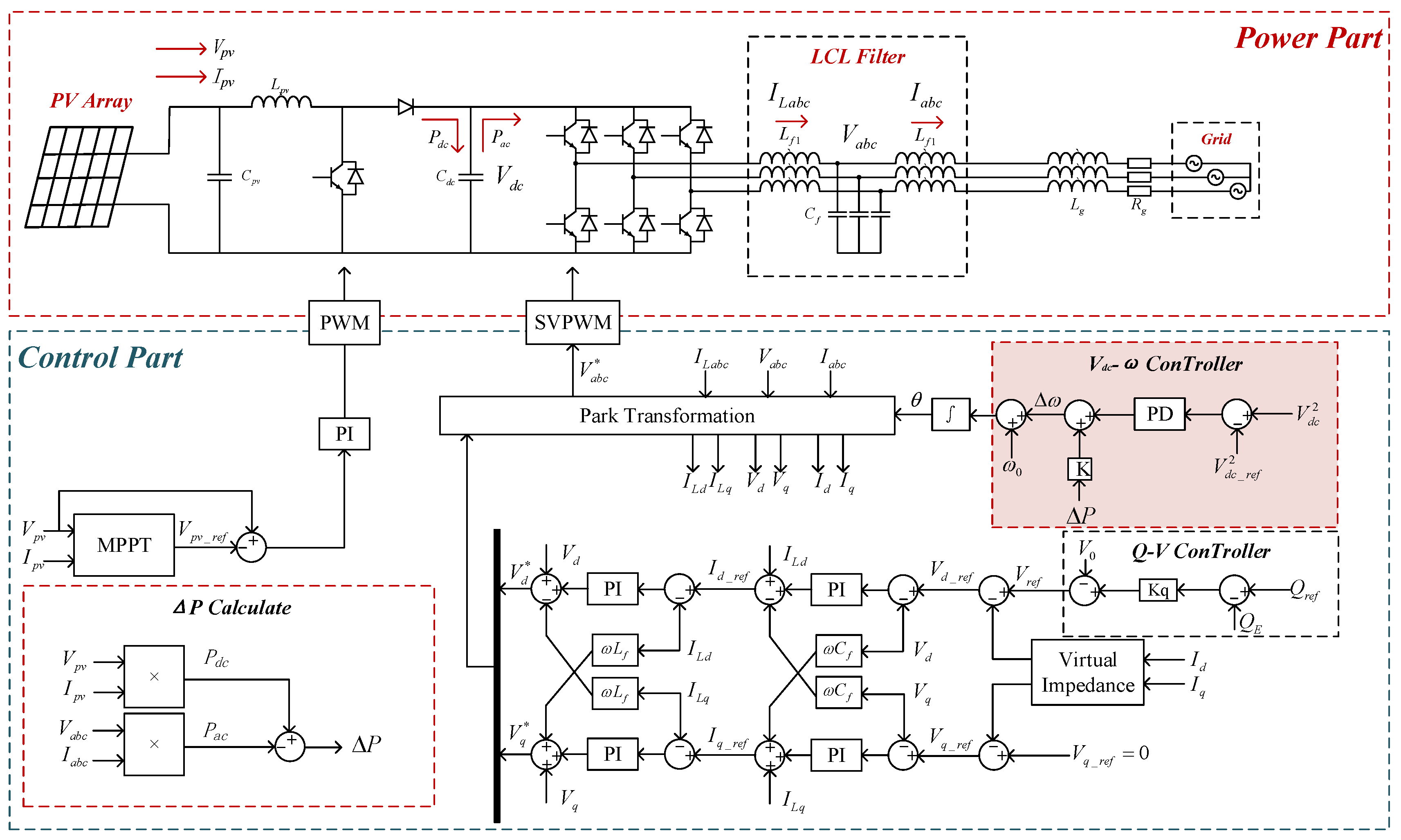
The overall topology of the two-stage grid-forming PV grid-connected system studied in this paper is shown in Figure 1. The system is mainly composed of five parts: PV array, preceding DC-DC conversion unit, DC-link capacitor, post-stage three-phase full-bridge inverter unit, LCL filter circuit, and grid equivalent impedance.
Compared with the single-stage PV grid-connected topology, the two-stage structure realizes electrical decoupling between the PV side and the inverter side through the preceding DC-DC circuit. It can not only boost the wide-range output voltage of the PV array to the stable DC-link voltage level required by the post-stage inversion, but also independently complete the functions of maximum power point tracking and grid-forming control. Thus, higher control flexibility is achieved. It is the mainstream topology for medium and high power PV grid-connected systems at present.
The output terminal of the PV array is connected in parallel with a capacitor Cpv to suppress the high-frequency ripple of the PV output voltage. The preceding stage adopts a boost circuit to realize control of the PV output voltage and maximum power point tracking by adjusting the duty cycle of the switching tube. The DC-link capacitor Cdc serves as the power buffer unit between the preceding and post stages, and its voltage dynamic characteristics directly determine the power balance capability and transient stability of the system. The post-stage three-phase bridge inverter converts DC energy into three-phase AC energy, which is connected to the grid after filtering switching harmonics through the LCL filter circuit. The grid side is connected in series with the equivalent impedance Zg = Rg + jωLg to simulate the impedance characteristics of transmission lines and transformers. The short-circuit ratio of the system can be adjusted by changing the impedance parameters to simulate the operating conditions of power grids with different strengths.
In this study, the maximum power point tracking control of the preceding stage, the reactive power-voltage droop control, the virtual impedance design, and the voltage-current double closed-loop control of the post stage all adopt mature control schemes in the field of grid-forming inverters. The principle is briefly introduced below as the theoretical basis of this research and a description of the integrity of the system design. The innovation of this paper lies in the adaptive virtual inertia synchronization control loop based on DC-side dynamics, which replaces the rotor motion equation of the traditional VSG, directly uses the DC-link voltage as the synchronization reference, and is the main research content and contribution of this paper.

2.2. PV Control

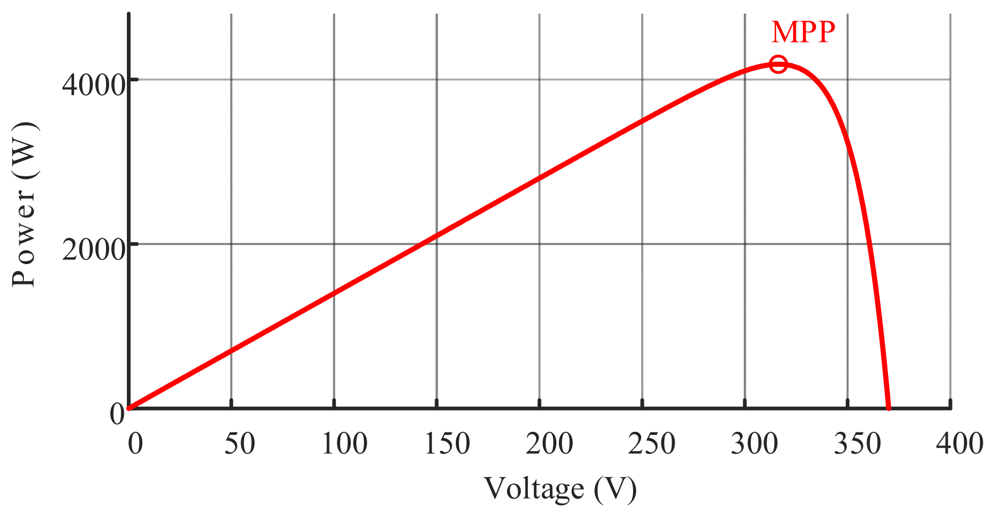
The output power of the PV array has nonlinear characteristics, and the relationship between its output power Ppv, output voltage Vpv and output current Ipv is significantly affected by meteorological factors such as irradiance and ambient temperature. As shown in Figure 2, under fixed irradiance and temperature conditions, the PV array has a unique maximum power point, corresponding to voltage Vmpp, current Impp, and power Pmpp. To maximize the utilization of solar energy, the preceding boost circuit needs to track the maximum power point of the PV array in real time through the MPPT algorithm.
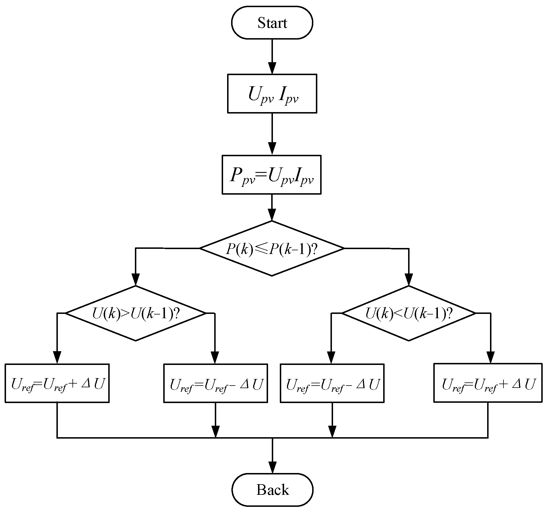
In this paper, the perturbation and observation method is adopted to realize PV maximum power point tracking. First a small perturbation increment ∆Vpv is periodically applied to the output voltage of the PV array. Then, the output power Ppv(k) and Ppv(k − 1) of the PV array before and after the perturbation in real time can be collected. The rationality of the perturbation direction is judged by comparing the power change trend. The voltage perturbation direction at the next moment is finally adjusted. The algorithm control flow is shown in Figure 3.

2.3. Synchronization Strategy Based on DC-Link Dynamics

The electromechanical transient characteristics of a synchronous generator are described by the rotor motion equation, which reflects the influence of the imbalance between the rotor mechanical power and electromagnetic power on the rotational speed and is the physical basis for power system frequency stability. Traditional VSG control emulates virtual inertia and damping by simulating this equation. The rotor motion equation in the Laplace transform domain is expressed as
2 H s ω ω 0 = P m P a c S b D ω ω 0 ω 0
where H is the rotational inertia of the synchronous generator, corresponding to the rotating mass of the synchronous generator; D is the damping coefficient, corresponding to the damping winding of the synchronous generator; Pm is the mechanical power; Pac is the electromagnetic power; ω0 is the rated angular frequency of the power grid; and Sb is the system power base value. This equation is used as the benchmark for derivation in this paper.
For the two-stage grid-forming PV system studied in this paper, the DC-link capacitor is the only energy storage element of the system, and its charging and discharging process corresponds to the power imbalance between the DC side and the AC side. According to the principle of power conservation, the power balance equation of the DC link is
P d c P a c = C d c V d c d V d c d t = 1 2 C d c s V d c 2
where Pdc is the PV output power (corresponding to the mechanical power Pm of the synchronous generator); Pac is the output electromagnetic power of the inverter; Cdc is the capacitance value of the DC-link capacitor; and Vdc is the DC-link voltage value.
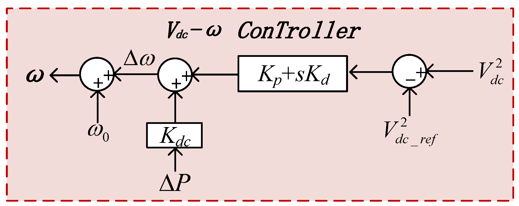
This paper abandons the independent rotor motion equation structure in the traditional VSG control method and adopts a synchronization control loop based on the square dynamics of the DC-link voltage, which directly uses the energy storage characteristics of the DC-link capacitor to realize system self-synchronization. The core idea of this control method is as follows: the difference between the square of the DC-link voltage and its reference value is used as the input to the synchronization loop. A proportional-derivative controller then generates the angular frequency reference for the system. Additionally, a feedforward term representing the power difference between the preceding-stage PV power and the post-stage power is introduced. This enables deep coupling between the power dynamics on the DC side and the synchronization characteristics on the AC side.
The basic structure of the synchronization control loop proposed in this paper is shown in Figure 4. Its inputs are the deviation of the square of the DC-link voltage and the power difference feedforward, and the output is the system angular frequency reference ω. In per-unit values, the control equation of the synchronization loop can be initially expressed as
ω = ω 0 + k p + s k d V d c 2 V d c _ r e f 2 + k d c P d c P a c
where ω0 is the rated angular frequency of the power grid; kp and kd are the proportional coefficient and differential coefficient of the synchronization loop, respectively; kdc is the power difference feedforward coefficient; and Vdc_ref is the reference value of the DC-link voltage. The nominal value form of the synchronization loop control equation can be expressed as
ω ω 0 = 1 + k p + s k d V d c 2 V d c _ r e f 2 V d c 0 2 + k d c S b P d c P a c
where Vdc0 is the reference value of the DC-link voltage under rated operating conditions. Taking the derivative of both sides of Equation (4), since Vdc_ref and ω0 are constants, their derivatives are zero. Thus:
s ω ω 0 = k p V d c 0 2 s V d c 2 + k d V d c 0 2 s 2 V d c 2 + s k d c S b P d c P a c
Considering that the response speed of PV output power is much slower than the grid transient process, sPdc = 0. Therefore, Equation (5) can be simplified as
s ω ω 0 = k p V d c 0 2 s V d c 2 + s k d V d c 0 2 s V d c 2 s k d c S b P a c
Substituting Equation (2) into Equation (6), and noting that sPdc = 0, we obtain
s ω ω 0 = 2 k p C d c V d c 0 2 P d c P a c + 2 k d C d c V d c 0 2 s P d c P a c s k d c S b P a c
Similarly, sPdc = 0. Let Edc0 be the energy stored in the capacitor at the rated operating point, i.e., Edc0 = 0.5 Vdc02Cdc. Combining like terms and transforming Equation (7) into the form of the rotor motion Equation (1), we obtain
E d c 0 k p ω 0 s ω = P d c P a c k d k p + E d c 0 k d c S b k p s P a c
To simplify the calculation, two reasonable assumptions are made: (1) the inductance of the transmission line is much larger than the resistance, so the line resistance can be ignored (valid for high-voltage transmission or inductance-dominated grid impedance); (2) the actual power angle δ is very small, so sin δδ. Based on these assumptions, the active power transmission equation can be approximated as
P a c = E U g X g θ θ 0
where E is the output voltage amplitude of the VSC, Ug is the grid voltage amplitude, Xg is the transmission line reactance, θ is the output voltage phase angle of the VSC, and θ0 is the grid phase angle. Taking the derivative of both sides of Equation (9),
s P a c = s E U g X g θ θ 0 = P 0 ω ω 0
where P0 = EUg/Xg. Substituting Equation (10) into Equation (8), we obtain
E d c 0 k p ω 0 s ω = P d c P a c k d k p + E d c 0 k d c S b k p P 0 ω 0 ω
Comparing Equation (11) with the rotor motion equation shown in Equation (1), the corresponding relationship between the control parameters and the virtual inertia and damping can be obtained:
E d c 0 k p ω 0 = 2 H S b ω 0 k d + E d c 0 k d c S b P 0 k p = D S b ω 0
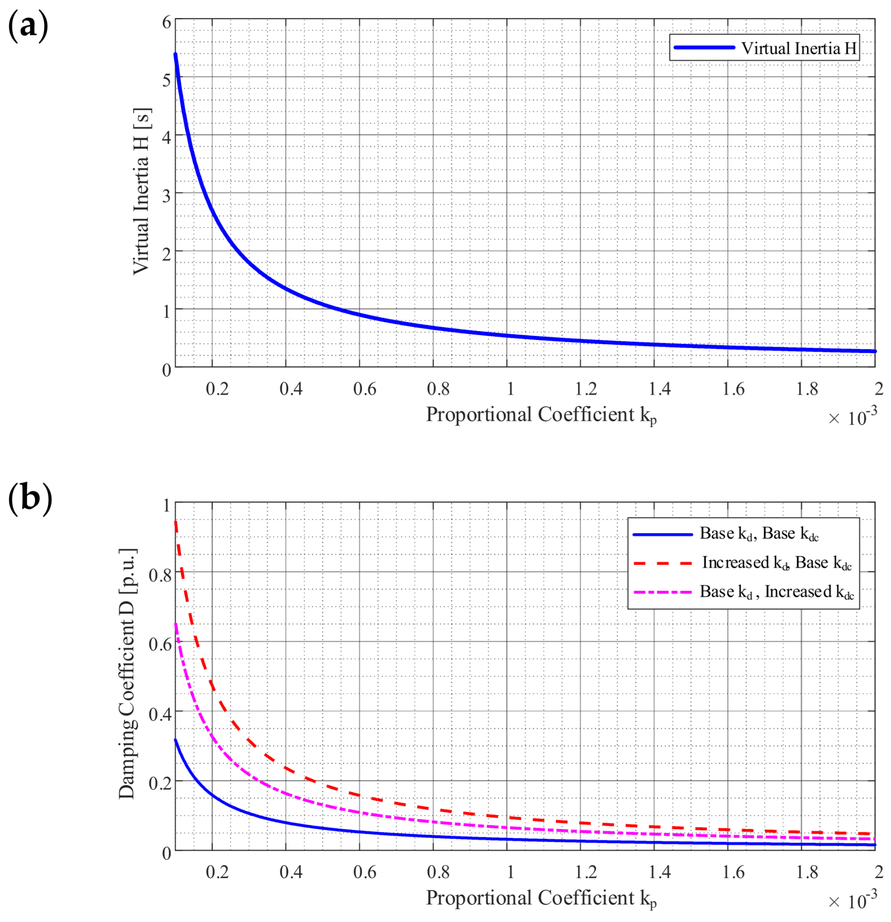
It can be seen from Equation (12) that the virtual inertia H is inversely proportional to the proportional coefficient kp, and the damping D is related to the proportional coefficient kp, the differential coefficient kd, and the feedforward coefficient kdc. This means that we can flexibly configure the inertia and damping characteristics of the system by adjusting the controller parameters kp, kd, and kdc. The relationship among virtual inertia, damping, and control parameters is shown in Figure 5.
However, for the two-stage PV system, the PV output power has significant randomness and volatility. If the traditional fixed-parameter control is adopted, it is difficult to achieve a balance between supporting the grid frequency with large inertia and maintaining the DC voltage stability with small inertia. Aiming at solving this contradiction, Section 3 will propose an adaptive virtual inertia control strategy considering the dynamic resources of the DC side.

2.4. Reactive Power-Voltage Loop

The droop control strategy is adopted for the reactive power and AC voltage amplitude of the grid-forming inverter, which simulates the excitation regulation characteristics of the synchronous generator. The basic principle of the reactive power-voltage droop control is that the deviation between the output reactive power of the inverter and its reference value is converted into the correction amount of the voltage amplitude through the droop coefficient, so that the AC voltage amplitude decreases linearly with the increase of the output reactive power. Its control equation is
V r e f = V 0 + k q Q r e f Q e
where Vref is the AC voltage amplitude reference; V0 is the rated phase voltage amplitude of the power grid; kq is the reactive droop coefficient; Qe is the output reactive power of the inverter; and Qref is the rated reactive power of the inverter.
The selection of the reactive droop coefficient kq needs to take into account the voltage regulation accuracy and the reactive power sharing effect: if kq is too large, it will lead to excessive deviation of the AC voltage amplitude and affect the power quality; if kq is too small, it will lead to excessively high output reactive power of the inverter and affect the power factor. In this paper, according to the rated capacity of the system and the allowable voltage deviation range, kq = 0.05 p.u. is selected; that is, when the inverter outputs the rated reactive power, the AC voltage amplitude drops by 5%.

2.5. Virtual Impedance

The core purpose of introducing virtual impedance into the grid-forming inverter is to improve the power-decoupling characteristics, suppress circulating current and harmonics, and enhance the fault ride-through capability. Compared with the unified virtual impedance design in the stationary coordinate system, the split-axis virtual impedance in the synchronous rotating coordinate system can realize independent adjustment of the d-axis and q-axis impedance characteristics and can specifically optimize the decoupling effect of the active power loop and the reactive power loop, which is a more commonly used high-precision implementation scheme in engineering.
In this paper, series-type split-axis virtual impedance is adopted, and the d-axis virtual impedance Zvd = Rvd + sLvd and the q-axis virtual impedance Zvq = Rvq + sLvq are designed. The virtual voltage drop is subtracted from the original voltage reference generated by the reactive power-voltage loop to obtain the corrected final voltage reference:
V d _ r e f = V d * R v d L v d d i d d t V q _ r e f = V q * R v q L v q d i q d t
where Vd* is the voltage reference output by the reactive power-voltage loop, and Vq* = 0 in this paper.

2.6. Voltage-Current Double Closed-Loop Control

The voltage reference generated by the synchronization loop and the reactive power-voltage loop needs to be quickly tracked through the voltage-current double closed-loop control, which is the core guarantee for the grid-forming inverter to output high-quality electric energy. This paper adopts a typical voltage-current double closed-loop control structure in the three-phase stationary coordinate system. The voltage outer loop adopts a PI controller, and the output is used as the reference of the current inner loop; the current inner loop also adopts a PI controller, and the output generates the driving signal of the switching tube through SVPWM modulation. To further improve the dynamic response speed and anti-interference ability of the system, cross-coupling feedforward and grid voltage and current feedforward are introduced in this paper to eliminate the coupling effect between d and q axes and to suppress grid voltage disturbances.

3. Design of Adaptive Virtual Inertia and Damping Coordination Control

3.1. Coupling Mechanism Between DC-Side Dynamic Constraints and Inertia Requirements

In the two-stage PV system, the DC-link capacitor Cdc is the key to power decoupling between the preceding and post stages, and also the only short-term energy storage element of the system. To reveal the internal relationship between PV output fluctuation and system inertia demand, this section conducts an in-depth analysis from the perspective of energy exchange.
According to the power balance equation shown in Equation (2), when the grid frequency fluctuates, the grid-forming inverter needs to adjust the DC-link voltage to release or absorb kinetic energy to support the frequency. Assuming that the energy released by the DC side during the transient process is ∆Edc, and the frequency change rate is ∆ω, the relationship shown in Equation (15) exists:
Δ E d c = 1 2 C d c V d c 0 2 V d c _ min 2 H S B Δ ω ω 0
To ensure that the DC-link voltage is not lower than Vdc_min, it is necessary to satisfy ∆E < ∆Emax, and the corresponding maximum frequency change rate is ∆ωmax. Thus, the maximum allowable value of virtual inertia can be obtained:
H m a x = ω 0 C d c ( V d c 0 2 V d c _ m i n 2 ) 4 S b Δ ω m a x
It can be seen from (11) that, with the same energy ∆Edc provided, the larger the virtual inertia H is set, the more energy the DC-link needs to release, resulting in a larger DC voltage drop ∆Vdc, which easily causes a serious voltage sag. Conversely, if H is too small, the change rate of the grid frequency cannot be effectively suppressed.
The key contradiction is that the output power Ppv of the PV array has significant randomness and intermittency. When the irradiance is sufficient, the system has a sufficient “energy margin” and can bear large virtual inertia to enhance the stability of the grid frequency. However, when the irradiance is insufficient, or cloud occlusion occurs, the input power of the preceding stage drops sharply. At this time, if the system maintains a large inertia operation, the DC-link will quickly drop to the undervoltage protection action point due to the lack of energy supplement, resulting in system disconnection. Therefore, it is necessary to establish a mechanism to dynamically adjust the virtual inertia according to the real-time PV output, so as to realize a dynamic balance between frequency support capability and DC voltage stability.

3.2. Adaptive Virtual Inertia Control Law Based on PV Output State

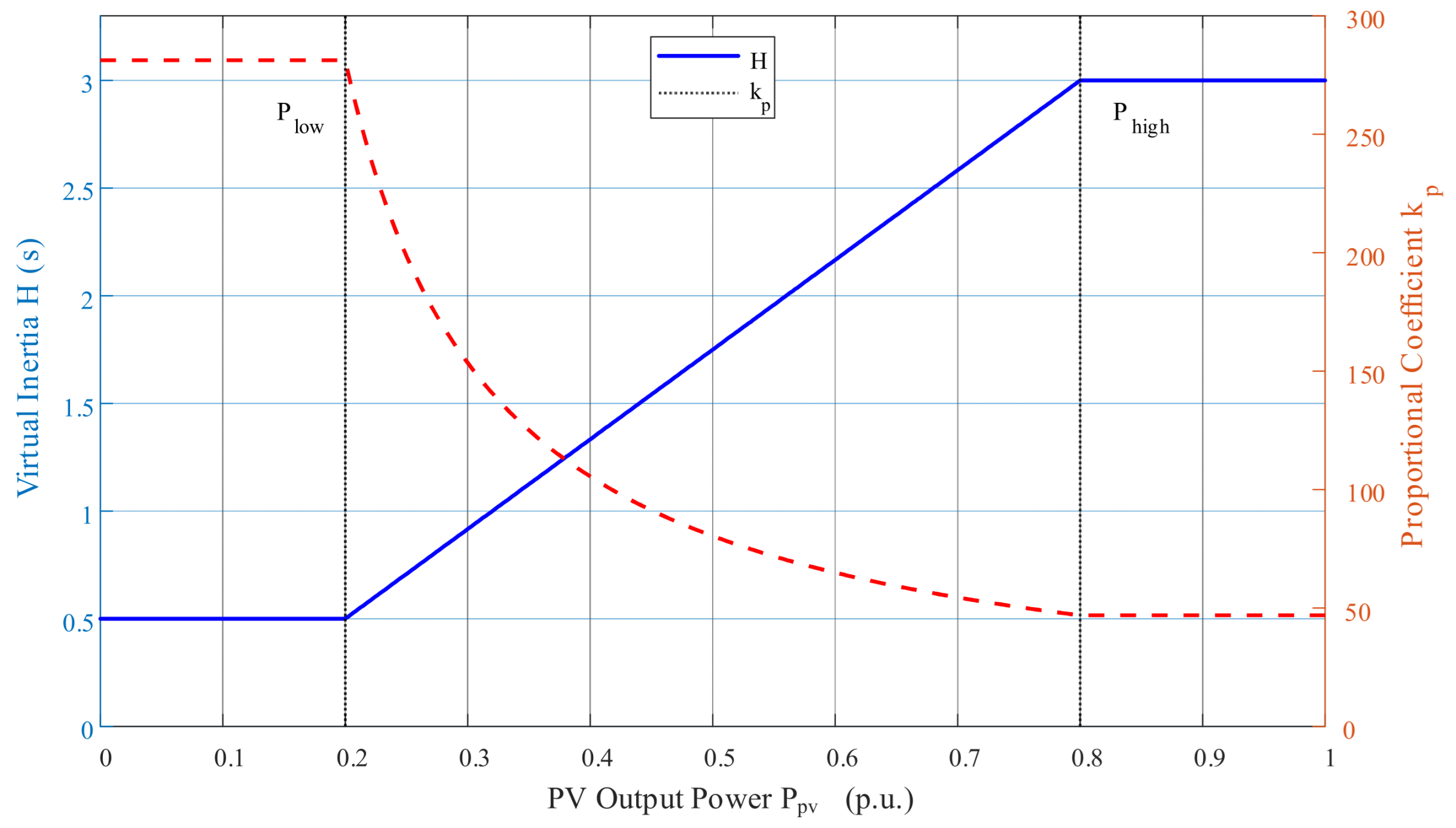
To address the limitation that fixed-parameter control cannot perform optimally across all operating conditions, this paper proposes a piecewise linear adaptive adjustment strategy based on the PV output power Ppv. The core idea of this strategy is to divide the system operating state into voltage priority mode and inertia support mode with a smooth transition mechanism.
This paper proposes a piecewise linear adaptive inertia adjustment function that enables the virtual inertia H to be dynamically adjusted within the range of Hmin, Hmax with change in the PV output power Ppv. The mathematical expression of the adaptive inertia H is
H ( P p v ) = H m i n 0 P p v < P l o w H m i n + H m a x H m i n P h i g h P l o w ( P p v P l o w ) P l o w P p v P h i g h H m a x P p v > P h i g h
where Plow and Phigh are the lower and upper threshold values of PV power, respectively. The selection of the piecewise thresholds Plow and Phigh is strictly based on the DC-side maximum releasable energy constraint and the inverter undervoltage protection requirements.
Plow is defined as the minimum PV output power at which the system can maintain stable operation with the maximum virtual inertia Hmax while satisfying the grid’s maximum allowable frequency deviation constraint. When the PV output is below this threshold, maintaining Hmax will cause the DC capacitor to release energy faster than it can be replenished, leading to DC voltage dropping below the undervoltage protection threshold. From Equation (15), the maximum energy that can be safely released by the DC capacitor is
Δ E max = 1 2 C d c V d c 0 2 V d c _ min 2
Based on the transient energy balance relationship, the energy required for inertia support is jointly provided by the DC capacitor energy storage and the real-time PV output. Considering the relationship between PV output power and DC-side energy replenishment rate, the lower threshold of PV power can be derived as
P l o w = P max Δ E max Δ t
where Pmax is the maximum PV output power, and ∆t is the typical duration of grid transient processes.
Phigh is defined as the minimum PV output power at which the system has a sufficient energy margin to provide maximum inertia support. Considering the volatility of PV output power and MPPT tracking error, Phigh = 0.9 Pmax is selected in this paper. This value ensures the maximum inertia support capability under rated operating conditions while leaving a 10% power margin to cope with small fluctuations in PV output.
When Ppv is lower than the threshold Plow, it is considered that the PV output is seriously insufficient, the system enters the voltage priority mode, and the minimum inertia Hmin is set to protect the DC voltage. When Ppv is higher than the threshold Phigh, the PV output is considered sufficient, the system enters the inertia support mode, and the maximum inertia Hmax is set to support the grid frequency. The linear transition is adopted in the middle area to ensure the smoothness of parameter changes and to avoid sudden changes in the system state.
To prevent the frequent switching of H caused by the small fluctuation of Ppv near the threshold, a first-order low-pass filter link or a slope limiter is introduced into the actual controller. Let Hraw be the original value calculated by Equation (17), then the actual output inertia command Href satisfies
d H r e f d t = s a t H r a w H r e f τ
where τ is the time constant, and sat is the saturation function, which is used to limit the parameter change rate.
It can be determined from Equations (12) and (17) that the virtual inertia H is inversely proportional to the synchronization loop proportional coefficient kp, so the calculation formula of kp that can be adjusted in real time is
k p = E d c 0 2 H r e f S b
Through real-time calculation of kp, adaptive tracking of virtual inertia to the PV output state is realized. The variation of virtual inertia H and proportional coefficient kp with PV output power is shown in Figure 6.

3.3. Damping Coordination Compensation

It can be seen from Equation (12) that the equivalent damping coefficient D of the system is not only determined by the differential term kd, but also coupled with kp, kd, and the feedforward coefficient kdc. In Section 3.2, we changed kp to adapt to the PV output. Without intervention, this change in kp will directly lead to fluctuation of the system damping characteristic D. In addition, if the damping is too small under low irradiance, the system is prone to low-frequency oscillation; if the damping is too large under high irradiance, the dynamic response speed of the system will be sacrificed. Therefore, a mechanism must be designed to decouple this parameter coupling.
To balance the suppression of low-frequency oscillations and the assurance of fast dynamic response, this paper sets the desired constant damping coefficient as Dref = 20 N·m·s/rad. This value is determined through root locus analysis based on the small-signal model of the system. The analysis shows that, when Dref = 20 N·m·s/rad, the damping ratio ζ of the system remains above 0.3 at all operating points, ensuring system stability and good dynamic response. The relationship between the damping ratio ζ and D is
ζ = D r e f 2 H max S b ω 0
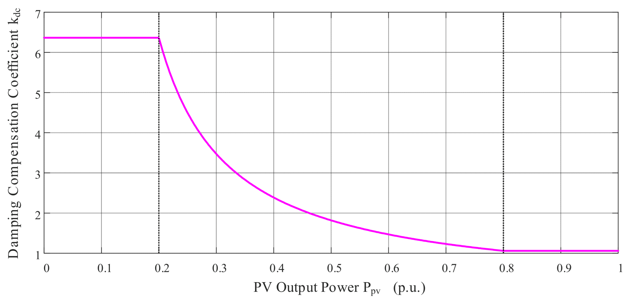
To achieve a constant damping coefficient D, the power-difference feedforward coefficient kdc is introduced as a degree of freedom for compensation. By rearranging the damping term expression in Equation (12) and setting it equal to Dref,
P 0 ω 0 E d c 0 S b 2 k p k d c = D r e f P 0 ω 0 k d S b k p
By combining like terms and shifting terms, the real-time compensation equation of kdc can be obtained:
k d c = S b E d c 0 D r e f S b k p ω 0 P 0 k d
This compensation mechanism is derived based on the linearized model of the system and effectively decouples kp and D.
During operation, the controller synchronously calculates kdc according to the real-time calculated kp using the above equation and updates it to the synchronization loop. In this way, no matter how kp changes with irradiance, the system can maintain the damping coefficient D constant at Dref through the dynamic compensation of kdc, thus improving the dynamic response performance of the system under complex operating conditions. The variation trend of the feedforward coefficient kdc is shown in Figure 7.

4. Verification and Case Analysis

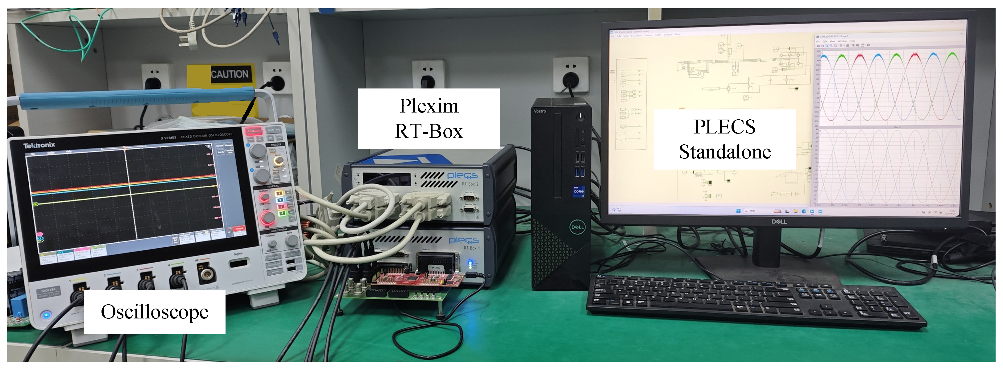
To comprehensively verify the effectiveness of the proposed adaptive virtual inertia control strategy considering DC-side dynamic resources in this paper, a two-stage grid-forming PV grid-connected inverter system is built based on the PLECS RT-Box hardware-in-the-loop (HIL) experimental platform (version 5.0.2), as shown in Figure 8. Experimental verification under multiple operating conditions is completed. First, the proposed synchronization control strategy based on DC-link voltage dynamics for virtual inertia and damping is verified. Then, two groups of typical extreme operating conditions are set for comparative experiments. One is the sudden change in output power caused by the sharp drop of PV solar irradiance, and the other is the power impact condition caused by a sudden increase in the grid-side load. The control group of the experiment adopts the traditional fixed-parameter grid-forming control strategy. During the experiment, the core observation indicators include three dimensions—the dynamic characteristics of the inverter output power at the point of common coupling (PCC), the drop and recovery characteristics of the DC-link voltage Vdc, and the grid-connected point frequency deviation Δω—to comprehensively evaluate the steady-state and dynamic performance of the control strategy.
This experiment adopts the semi-physical hardware-in-the-loop verification scheme. The main circuit topology and full control link model of the system are built using PLECS Standalone software. The compiled model is downloaded to the RT-Box simulator for real-time operation, and the system operation data are collected in real time through an oscilloscope and a host computer. Since the stable operation and inertia support capability of grid-forming inverters in weak grid scenarios are the core application requirements in the current field of new energy grid connection, the system short-circuit ratio is set to 2.5 in this experiment to simulate the typical weak grid operating environment. The key experimental parameters of the system are shown in Table 2.

4.1. Basic Verification of the Synchronization Strategy

The experiment in this subsection aims to verify the proposed synchronization control strategy based on DC-link voltage dynamics for the rotor motion characteristics of synchronous generators. First, SCR = 2.5 is selected as the baseline weak grid condition, as SCR < 3 is typically considered a weak grid in power system stability studies, and SCR = 2.5 is a typical value between 2 and 3, effectively simulating weak grid dynamics (such as lower short-circuit capacity and larger equivalent impedance) while being engineering-representative. To further verify the stability of the proposed strategy under weaker grid conditions, a comparative experiment with SCR = 2.0 is additionally conducted in this subsection.
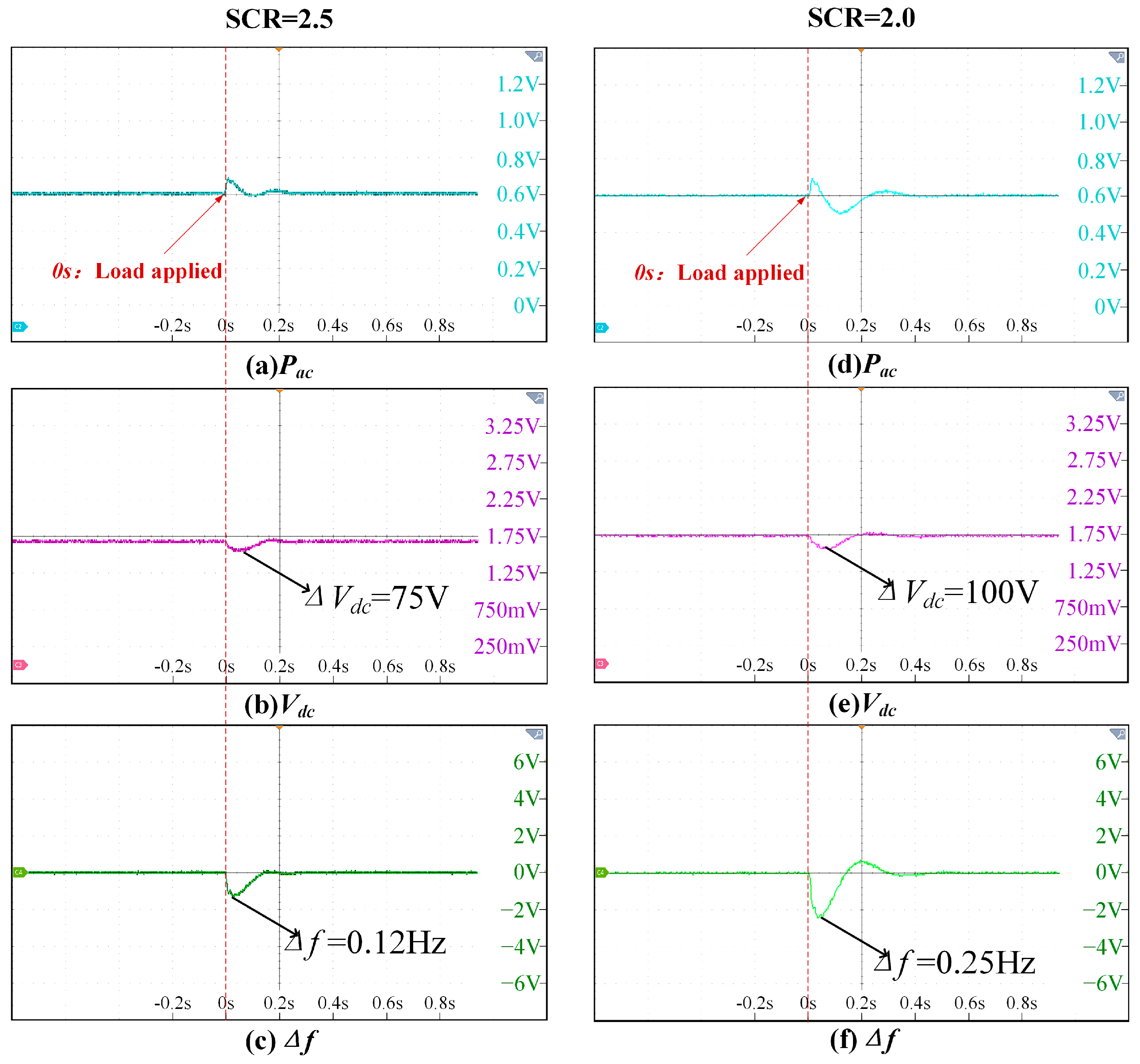
The experimental operating conditions are set as follows: the PV array maintains the rated solar irradiance, the PV output power is stable near the rated operating condition of 1 p.u., the front-stage boost circuit realizes stable MPPT control through the perturbation and observation method, and the system DC-link voltage is stable at the rated value of 850 V. At t = 0 s, a 0.3 p.u. load is connected to the grid side to simulate the scenario of a small fluctuation of grid load. The dynamic response characteristics of the system are tested under both SCR = 2.5 and SCR = 2.0 conditions. The experimental results are shown in Figure 9.
As can be seen from Figure 9, under both short-circuit ratio conditions, the inverter output power Pac rises rapidly at the moment of load connection to respond to the load change. According to the DC link power balance Equation (2), Pac > Pdc at this time, the DC-link capacitor releases energy, and Vdc has a temporary drop. Under SCR = 2.5, the voltage drops by about 75 V (approximately 9%) and recovers to the rated value within 200 ms with almost no overshoot and oscillation; the system frequency deviation Δf drops by a maximum of 0.12 Hz and also converges to zero within 200 ms. Under the weaker SCR = 2.0 condition, due to the increased grid impedance, the system’s damping capability for power disturbances decreases, leading to a larger Vdc drop of 100 V (approximately 12%) and a maximum frequency drop of 0.25 Hz. Both recover to stability within 300 ms without continuous oscillation or overshoot. These results indicate that, even when the short-circuit ratio drops to 2.0, the proposed synchronization control strategy can effectively emulate virtual inertia and damping through the energy storage dynamics of the DC-link capacitor, maintaining stable system operation and verifying its robustness under weaker grid conditions.
In summary, the proposed synchronization control strategy can effectively realize the equivalent simulation of virtual inertia and damping of synchronous generators through the energy storage dynamic characteristics of the DC-link capacitor. It exhibits good dynamic response characteristics and steady-state operation capability under both SCR = 2.5 and SCR = 2.0 weak grid conditions, laying a foundation for subsequent verification of the adaptive control strategy.

4.2. Performance with a Sudden Drop in PV Output

The experiment in this subsection aims to verify the protection capability of the proposed adaptive virtual inertia control strategy for DC-link voltage under the extreme operating condition of a sudden change in solar irradiance and a sharp drop of PV output power, as well as the performance difference compared with the traditional fixed-parameter control.
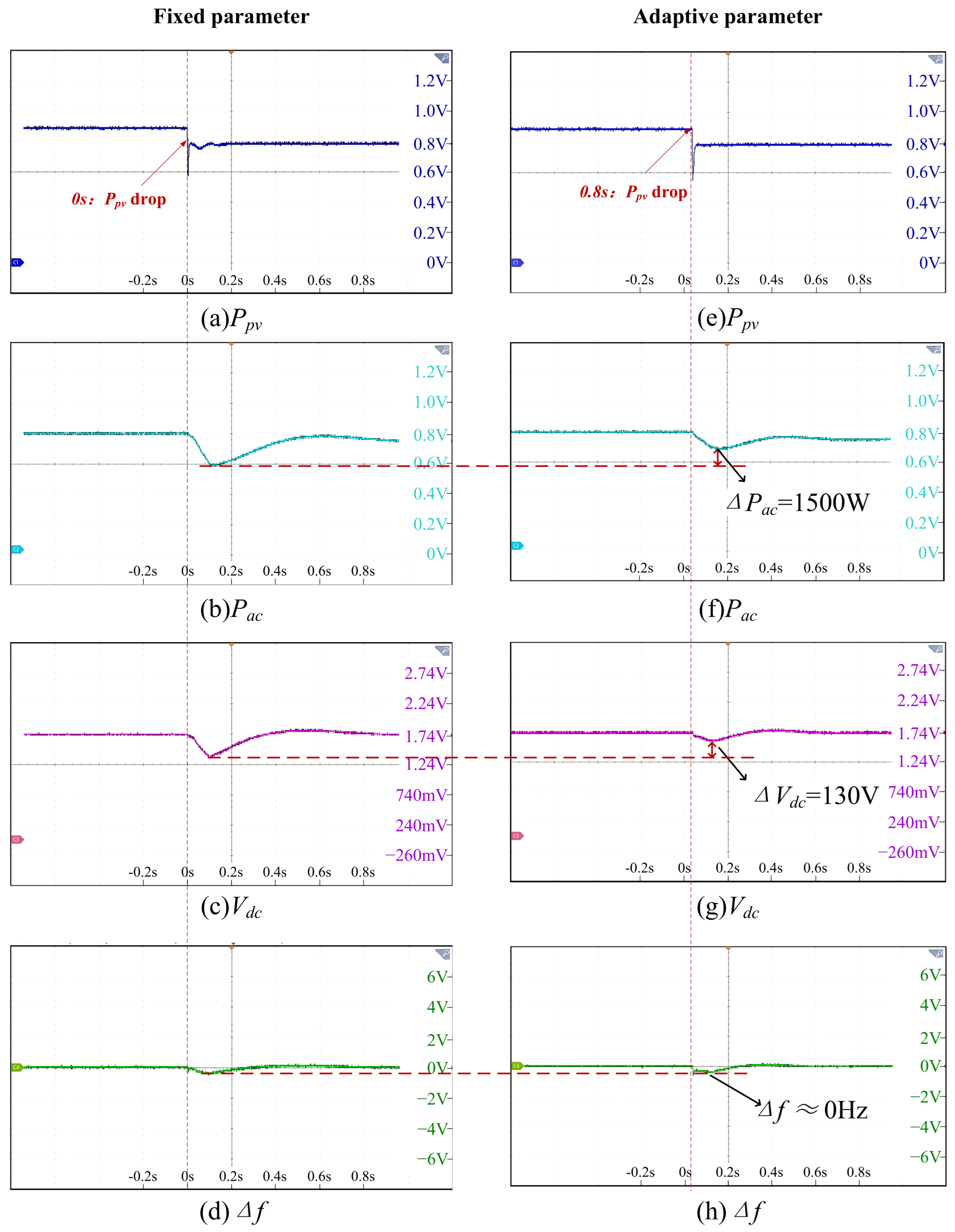
The experimental operating conditions are as follows: the system initially operates under the rated irradiance condition, the PV output power is stable at 0.9 p.u., the DC-link voltage is stable at the rated value of 850 V, and the inverter operates stably with a 0.5 p.u. rated load. At t = 0 s, by simulating the sudden drop of solar irradiance of the PV array, the PV output power drops from 0.9 p.u. to 0.8 p.u., and the MPPT algorithm of the front-stage boost circuit quickly tracks the maximum power point under the new operating condition. The dynamic responses of the system under the traditional fixed-parameter control and the proposed adaptive control strategy are tested. The results are shown in Figure 10, where Figure 10a is the result of fixed-parameter control, and Figure 10b is the result of the proposed adaptive control strategy in this paper.
From comparative analysis of the experimental results, it can be seen that, using the two control strategies, the front-stage MPPT algorithm can quickly lock the maximum power point under the current irradiance within 20 ms to ensure maximum utilization of PV energy, but there are differences in the dynamic characteristics of the DC side and the AC side of the system.
From comparative analysis of the experimental results, it can be seen that, at the moment of irradiance drop, the front-stage MPPT can quickly lock the maximum power point under the current irradiance within 20 ms, verifying the good dynamic characteristics of the MPPT. Compared with the fixed-parameter control strategy, the adaptive parameter control strategy reduces the virtual inertia according to the change in PV output based on the piecewise linear adjustment strategy shown in Equation (17), which reduces the overshoot of the AC output power Pac by 1500 W and the DC-link voltage Vdc drop amplitude by 130 V, while the system frequency drop amplitude is almost the same. The comparison of key parameters is shown in Table 3.
As can be seen from the comparison in Table 3, with fixed inertia control, the DC-link voltage drops sharply to 645 V, posing a risk of disconnection; the adaptive control reduces the virtual inertia in real time according to the change in PV output, limiting the DC-link voltage drop amplitude to 75 V, which is 63.4% lower than that seen with fixed inertia control, and raising the minimum voltage to 775 V, ensuring stable system operation. The frequency nadir is 49.96 Hz with both control strategies, which meets the allowable deviation requirements of the power grid; at the same time, the AC power overshoot with adaptive control is reduced by 60.0%, achieving a smooth power transition.
From the above analysis, it can be concluded that the adaptive parameter control strategy prioritizes ensuring DC voltage safety on the premise of controllable frequency deviation, preventing the inverter from shutting down and disconnecting from the grid due to bus voltage problems.

4.3. Performance Verification with a Sudden Load Increase

The experiment in this subsection aims to verify the DC voltage protection capability and stable operation performance of the proposed adaptive control strategy under the power impact condition of a sudden load increase on the grid side in the scenario of low PV output, which is also the core extreme operating condition of the two-stage energy-storage-free grid-forming PV inverter.
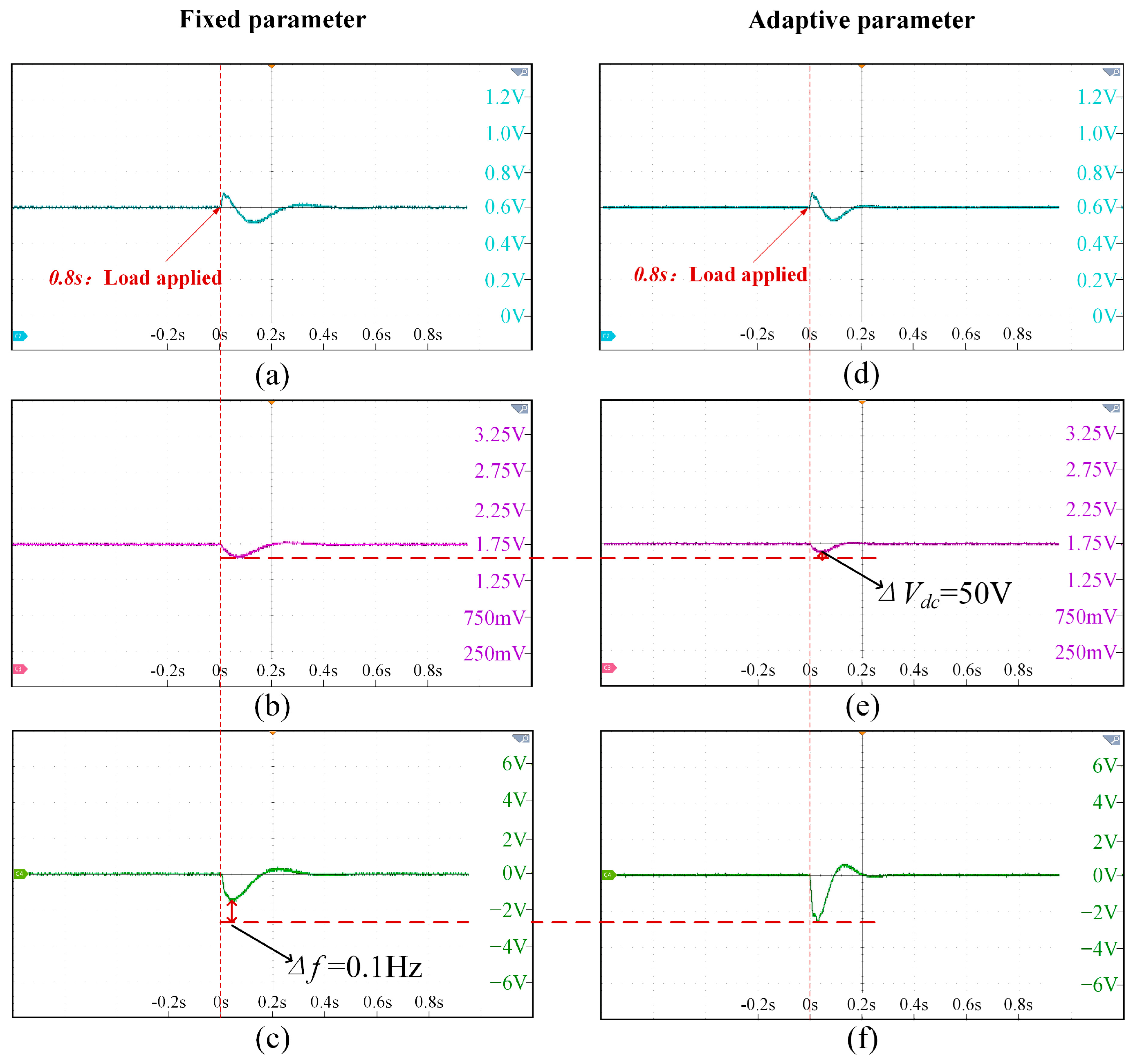
The experimental operating conditions are as follows: the system initially operates under low irradiance conditions, the PV output power is stable at 0.5 p.u., which is below the low power threshold Plow set in Equation (19), the DC-link voltage is stable at the rated value of 850 V, and the inverter operates stably without load. At t = 0 s, a 0.3 p.u. resistive load is suddenly added to the grid side, forming a large power gap. The dynamic responses of the system with the traditional fixed-parameter control strategy and the proposed adaptive control strategy are tested. The results are shown in Figure 11, where Figure 11a is the result of fixed-parameter control, and Figure 11b is the result of the proposed adaptive control strategy in this paper.
From the above figure, it can be seen that, under low irradiance conditions, compared with the fixed-parameter control strategy, the adaptive parameter control strategy reduces the virtual inertia according to the change in PV output based on the piecewise linear adjustment strategy shown in Equation (17), which reduces the overshoot of the AC output power Pac and the DC-link voltage Vdc drop amplitude by 50 V, while the system frequency drop amplitude increases by 0.1 Hz. The fixed-parameter control trades off voltage safety for a smaller frequency drop; the adaptive control prioritizes ensuring DC voltage safety on the premise of controllable frequency deviation. The comparison of key parameters is shown in Table 4.
As can be seen from the comparison in Table 4, with fixed inertia control, the DC-link voltage drops to 750 V, while the adaptive control operates in voltage priority mode in advance, limiting the energy release rate of the DC-link capacitor at the control level, reducing the DC voltage drop amplitude by 50.0% and raising the minimum voltage to 800 V, ensuring uninterrupted grid-connected operation. In terms of frequency, the frequency nadir with adaptive control is 49.78 Hz, which is 0.1 Hz lower than that with fixed inertia control, but still within the allowable range of the power grid; at the same time, benefiting from the constant damping compensation mechanism, the frequency settling time is shortened by 37.5%, converging to the rated value within 200 ms without continuous oscillation.
To verify the effectiveness of the proposed damping compensation mechanism, we focus on the frequency response waveforms shown in Figure 11c,f. As shown in Figure 11f, with adaptive control, the system frequency exhibits a good second-order dynamic response after the load increase. The frequency first drops rapidly to 49.78 Hz (the nadir), then smoothly rebounds and converges quickly to the steady state. This waveform has a slight underdamped characteristic with very small overshoot (<5%) and no continuous oscillation. In contrast, the frequency response of the fixed-parameter control in Figure 11c shows a slower “rebound” process and a longer settling time (320 ms > 200 ms). This indicates that the proposed damping compensation mechanism successfully maintains system damping within an ideal range (close to critical damping), avoiding both the sluggish response of overdamping and the potential oscillations of underdamping.
From the above analysis, it can be concluded that, under low irradiance conditions, the maximum releasable energy ∆Emax of the DC-link capacitor is substantially reduced, and the fixed large inertia control ignores this condition, making it easier for the voltage to drop to a dangerous value; while the proposed strategy ensures the safe and stable operation of the system by matching the PV output power and the virtual inertia limit in real time.

5. Conclusions

This paper addresses the inherent contradiction between virtual inertia support and DC-link voltage stability in two-stage grid-forming PV inverters by proposing an adaptive virtual inertia control strategy considering DC-side dynamic resources. The proposed strategy abandons the independent rotor motion equation structure of traditional VSG control, realizes natural emulation of virtual inertia and damping through a synchronization loop based on the square dynamics of DC-link voltage, and establishes a quantitative mapping relationship between control parameters and system dynamic characteristics. In addition, a piecewise linear inertia control law adjusted with PV output power and a power-difference feedforward damping coordination compensation mechanism are designed, achieving dynamic balance between system transient stability and grid friendliness under all operating conditions.
The PLECS RT-Box hardware-in-the-loop experimental results demonstrate that, compared with traditional fixed-parameter control, the proposed strategy reduces the DC-link voltage drop amplitude by 63.4% and the AC power overshoot by 60.0% under sudden PV output drop conditions, effectively avoiding system instability and disconnection. Under low-irradiance sudden load increase conditions, it reduces the DC voltage drop amplitude by 50.0% and shortens the frequency settling time by 37.5%, while maintaining frequency support capability that complies with grid standards.
This study overcomes the limitation of the ideal DC voltage source assumption in traditional grid-forming control and establishes a quantitative matching relationship between DC-side dynamic resources and AC-side inertia support capability, providing a general control design framework for the engineering application of grid-forming PV inverters. The proposed strategy realizes adaptive inertia adjustment without additional energy storage devices, significantly reducing system cost and complexity. It can be directly applied to various new energy grid integration scenarios such as distributed PV power plants and offshore PV clusters and has important engineering value for improving the inertia level and anti-disturbance capability of high-proportion new energy power systems.

Author Contributions

Conceptualization, Y.H. and C.W.; methodology, Y.H.; software, Y.H.; validation, Y.H., C.W., C.J. and D.Q.; formal analysis, Y.H.; investigation, Y.H.; resources, Y.H.; data curation, Y.H.; writing—original draft preparation, Y.H.; writing—review and editing, Y.H.; visualization, Y.H.; supervision, Y.H.; project administration, Y.H.; funding acquisition, C.W. All authors have read and agreed to the published version of the manuscript.

Funding

This work is supported by the Science and Technology Program of State Grid Jiangsu Electric Power Co. (Grant number: J2025007).

Data Availability Statement

The original contributions presented in this study are included in the article. Further inquiries can be directed to the corresponding author.

Conflicts of Interest

All authors are employed by the State Grid Jiangsu Electric Power Company. The remaining authors declare that the research was conducted in the absence of any commercial or financial relationships that could be construed as a potential conflict of interest; The authors declare that this study received funding from the Science and Technology Program of State Grid Jiangsu Electric Power company. The funder was not involved in the study design, collection, analysis, interpretation of data, the writing of this article or the decision to submit it for publication.

References

  1. Li, M.; Yao, Z.; Bao, B. Review and Prospect of New Transient Voltage Stability Issues in Power Systems with High Proportion of Renewables and Power Electronics. Proc. Chin. Soc. Electr. Eng. 2026, 46, 462–476. [Google Scholar]
  2. Xie, X.; He, J.; Mao, H.; Li, H. New Issues and Classification of Power System Stability with High Shares of Renewables and Power Electronics. Proc. Chin. Soc. Electr. Eng. 2021, 41, 461–474. [Google Scholar]
  3. Lei, Y.; Li, G.; Wang, W.; Guoqing, H.E.; Zixuan, G.U.O. Comparison of Impedance Characteristics and Oscillation Mechanism for Grid Following and Grid Forming Renewable Energy. Proc. Chin. Soc. Electr. Eng. 2025, 45, 150–162. [Google Scholar]
  4. Zhan, C.; Wu, H.; Wang, X.; Tian, J.; Wang, X.; Lu, Y. An Overview of Stability Studies of Grid-Forming Voltage Source Converters. Proc. Chin. Soc. Electr. Eng. 2023, 43, 2339–2358. [Google Scholar]
  5. Long, B.; Hu, C.; Chen, Z.; Hu, J.; Rodríguez, J. Transient Stability Analysis and Virtual Power Compensation of a Virtual Synchronous Generator Under Low-Voltage Fault. IEEE Trans. Power Electron. 2024, 39, 12803–12814. [Google Scholar] [CrossRef]
  6. Oboreh-Snapps, O.; She, B.; Fahad, S.; Chen, H.; Kimball, J.; Li, F.; Cui, H.; Bo, R. Virtual Synchronous Generator Control Using Twin Delayed Deep Deterministic Policy Gradient Method. IEEE Trans. Energy Convers. 2024, 39, 214–228. [Google Scholar] [CrossRef]
  7. Wu, H.; Ruan, X.; Yang, D.; Chen, X.; Zhao, W.; Lv, Z.; Zhong, Q.-C. Small-Signal Modeling and Parameters Design for Virtual Synchronous Generators. IEEE Trans. Ind. Electron. 2016, 63, 4292–4303. [Google Scholar] [CrossRef]
  8. Wang, B.; Burgos, R.; Wen, B. Grid-Forming Inverter Control Strategy with Improved Fault Ride Through Capability. In Proceedings of the 2022 IEEE Energy Conversion Congress and Exposition (ECCE), Detroit, MI, USA, 9–13 October 2022; pp. 1–8. [Google Scholar]
  9. Chen, Y.; Han, W.; Hu, Y.; Zhang, Y. Adaptive Control for Improved Virtual Synchronous Generator Under Imbalanced Grid Voltage. IEEE Open J. Ind. Electron. Soc. 2024, 5, 722–736. [Google Scholar] [CrossRef]
  10. Zhao, Z.; Li, H.; Shi, L.; Wu, F.; Lin, M.; Fu, H. Adaptive Control of Inertia and Damping in Grid-Forming Photovoltaic-Storage System. Sustainability 2025, 17, 9540. [Google Scholar]
  11. Moutevelis, D.; Paspatis, A.; Cheah-Mañe, M.; Gomis-Bellmunt, O. Impact of DC Dynamics of Grid-Forming Converters on Transmission System Stability. In Proceedings of the 2025 IEEE Kiel PowerTech, Kiel, Germany, 29 June–3 July 2025; pp. 1–6. [Google Scholar]
  12. Arghir, C.; Dorfler, F. The Electronic Realization of Synchronous Machines: Model Matching, Angle Tracking, and Energy Shaping Techniques. IEEE Trans. Power Electron. 2020, 35, 4398–4410. [Google Scholar] [CrossRef]
  13. Huang, L.; Xin, H.; Wang, Z.; Wu, K.; Wang, H.; Hu, J.; Lu, C. A Virtual Synchronous Control for Voltage-Source Converters Utilizing Dynamics of DC-Link Capacitor to Realize Self-Synchronization. IEEE J. Emerg. Sel. Top. Power Electron. 2017, 5, 1565–1577. [Google Scholar] [CrossRef]
  14. Subotic, I.; Gros, D. Power-Balancing Dual-Port Grid-Forming Power Converter Control for Renewable Integration and Hybrid AC/DC Power Systems. IEEE Trans. Control Netw. Syst. 2022, 9, 1949–1961. [Google Scholar] [CrossRef]
  15. Girona-Badia, J.; Lacerda, V.A.; Spier, D.W.; Prieto-Araujo, E.; Gomis-Bellmunt, O. Resource-Aware Grid-Forming Synchronization Control: Design, Analysis and Validation. IEEE Trans. Energy Convers. 2025, 40, 2548–2561. [Google Scholar] [CrossRef]
  16. Roy, S.; Villegas Pico, H.N. Transient Stability and Active Protection of Power Systems with Grid-Forming PV Power Plants. IEEE Trans. Power Syst. 2023, 38, 897–911. [Google Scholar]
  17. Cai, W.; Wen, B.; Johnson, B. Grid-Forming Control of Two-Stage PV Systems Under Capacity Constraints. In Proceedings of the 2025 IEEE 26th Workshop on Control and Modeling for Power Electronics (COMPEL), Knoxville, TN, USA, 22–26 June 2025; pp. 1–8. [Google Scholar]
  18. Pawar, B.; Batzelis, E.I.; Chakrabarti, S.; Pal, B.C. Grid-Forming Control for Solar PV Systems with Power Reserves. IEEE Trans. Sustain. Energy 2021, 12, 1947–1959. [Google Scholar] [CrossRef]
  19. Lin, Q.; Shijo, T.; Ogawa, K.; Uno, H.; Kanekiyo, Y.; Arai, J. Inertia Evaluations on Grid Forming Inverters with Virtual Synchronous Generator Control Applied to Photovoltaic Power Systems. In Proceedings of the 2022 IEEE Energy Conversion Congress and Exposition (ECCE), Detroit, MI, USA, 9–13 October 2022; pp. 1–6. [Google Scholar]
  20. Luo, C.; Ma, X.; Liu, T.; Wang, X. Adaptive-Output-Voltage-Regulation-Based Solution for the DC-Link Undervoltage of Grid-Forming Inverters. IEEE Trans. Power Electron. 2023, 38, 12559–12569. [Google Scholar] [CrossRef]
  21. Kong, L.; Wu, C.; Xu, J.; Wang, J.; Wang, Y. Enhanced DC-Link Voltage Synchronization Control for Grid-Forming Photovoltaic Systems Considering PV Power Dynamics and Grid Strength Adaptability. IEEE Trans. Energy Convers. 2025, 40, 2610–2623. [Google Scholar] [CrossRef]
Figure 1. Overall control scheme of the two-stage PV grid-connected inverter. Note: Different colors (red and blue) are used to distinguish the Power Part from the Control Part. Asterisks (*) denote reference values. Arrows indicate the direction of signal flow.
Electronics 15 02667 g001
Figure 2. Output power curve of the PV array.
Electronics 15 02667 g002
Figure 3. Control block diagram of the perturbation and observation method.
Electronics 15 02667 g003
Figure 4. Diagram of the synchronization strategy based on DC-link dynamics.
Electronics 15 02667 g004
Figure 5. Relationship among virtual inertia, damping, and control parameters: (a) relationship between H and kp; (b) relationship between D and kp, kd,, and kdc.
Electronics 15 02667 g005
Figure 6. The variation of adaptive virtual inertia H and its corresponding proportional coefficient kp with PV output power.
Electronics 15 02667 g006
Figure 7. Damping compensation coefficient kdc with adaptive inertia regulation.
Electronics 15 02667 g007
Figure 8. The HIL experimental platform.
Electronics 15 02667 g008
Figure 9. System waveform after the load is applied: (a,d) Pac; (b,e) Vdc; (c,f) ∆f.
Electronics 15 02667 g009
Figure 10. Dynamic waveforms of the system with a sudden drop in PV output: (a,e) PV output power; (b,f) AC output power; (c,g) DC-bus voltage; (d,h) frequency deviation.
Electronics 15 02667 g010
Figure 11. Dynamic waveforms of the system under a sudden load increase: (a,d) AC output power; (b,e) DC-bus voltage; (c,f) frequency deviation.
Electronics 15 02667 g011
Table 1. Comparison of core technical characteristics with existing research works.
Comparison DimensionTraditional VSG Control [7,8,9,10]Control Based on DC Voltage Synchronization [12,13,14]Resource-Aware GFM Control [15,16]Proposed Work
Consideration of DC-side dynamic characteristics×
Consideration of DC-side resource constraints××
Dynamic matching between inertia and DC-side output power××
Solution to inertia-damping coupling problem-×
Table 2. Key experimental parameters.
ParameterValueParameterValue
Po15 kWCdc2 mF
Vg380 VCpv1 mF
Vdc850 VLpv15 μH
Grid frequency f050 HzH2~5 kg∙m2
Lf12 mHD20 N∙m∙s/rad
Cf3.3 μFPload5 kW
Lg12 mHSwitching frequency fsw10 kHz
Rg0.5 ΩSCR2.5
Table 3. Performance comparison under sudden PV output drop conditions.
Performance IndexFixed ParameterAdaptive ParameterImprovement
Minimum DC-link voltage645 V775 V+20.2%
DC-link voltage drop amplitude205 V75 V+63.4%
Frequency nadir49.96 Hz49.96 Hz0
AC power overshoot2.5 kW1 kW+60%
System stabilityRisk of disconnectionStable-
Table 4. Performance comparison under sudden load increase conditions.
Performance IndexFixed ParameterAdaptive ParameterImprovement
Minimum DC-link voltage750 V800 V+6.7%
DC-link voltage drop amplitude100 V50 V+50%
Frequency nadir49.88 Hz49.78 Hz−0.2%
Frequency settling time320 ms200 ms+37.5%
Disclaimer/Publisher’s Note: The statements, opinions and data contained in all publications are solely those of the individual author(s) and contributor(s) and not of MDPI and/or the editor(s). MDPI and/or the editor(s) disclaim responsibility for any injury to people or property resulting from any ideas, methods, instructions or products referred to in the content.