Article

Analysis of Winding Losses in Permanent Magnet Synchronous Motors with Multilayer Thin Flat-Wire Windings


1
School of Electrical Engineering, Shenyang University of Technology, Shenyang 110870, China
2
Technology Center, Xiamen Tungsten Co., Ltd., Xiamen 361015, China
3
Transmission Technology Research Institute, Tsingshan Industrial Co., Ltd., Chongqing 402761, China
*
Author to whom correspondence should be addressed.
Electronics 2026, 15(12), 2665; https://doi.org/10.3390/electronics15122665
Submission received: 14 May 2026 / Revised: 10 June 2026 / Accepted: 11 June 2026 / Published: 16 June 2026
(This article belongs to the Special Issue Modeling and Control of Power Converters for Power Systems)

Abstract

Flat-wire windings have been widely used in high-power-density electric vehicle motors because of their high slot fill factor and high efficiency. However, conventional flat-wire conductors usually have relatively large cross-sectional dimensions, which may lead to significant AC winding losses under high-frequency operation due to the combined effects of the rotor magnetic field and the armature-reaction field. To address this issue, this paper proposes a multilayer thin flat-wire continuous-wave winding and its end-winding transposition method. The parallel multilayer thin flat-wire structure effectively suppresses AC losses by reducing the characteristic dimension of each conductor, while the end-winding transposition method reduces or even eliminates circulating-current losses among parallel strands without compromising slot utilization. An analytical calculation method is established to investigate the AC loss characteristics of the multilayer thin flat-wire winding, and the main influencing factors of winding losses are analyzed. To address the circulating-current loss issue, the loss suppression effect of the transposition method is quantitatively evaluated, and an intermittent transposition method with both effective circulating-current suppression and fewer end-winding crossovers is proposed. Finally, the proposed method is validated by finite-element analysis (FEA) and prototype experiments. The results show that the proposed winding can significantly reduce AC losses over a wide speed range, providing a low loss and manufacturable winding design solution for high-power-density electric vehicle traction motors.

1. Introduction

Permanent magnet synchronous motors (PMSMs) have become one of the most promising candidates for electric vehicle traction systems because of their high torque density, high efficiency, and excellent field-weakening capability [1,2]. With the continuous development of traction motors toward higher-speed operation, loss control over a wide speed range has become increasingly critical [3]. Under high-speed operating conditions, winding losses caused by skin and proximity effects increase significantly. These losses not only directly affect the overall motor efficiency, but also aggravate local temperature rise within the stator slots, thereby limiting the continuous output capability and operational reliability of the motor [4]. Therefore, effectively reducing AC winding losses while maintaining high power density and manufacturing feasibility has become a key issue in motor design.
Hairpin flat-wire windings have been widely adopted in electric vehicle traction motors because of their high slot fill factor, low DC resistance, short end-winding length, favorable thermal performance, and suitability for automated manufacturing. Compared with conventional round-wire windings, flat-wire windings can improve the copper utilization in the slot and enhance the heat-transfer path between the winding and the stator core [5,6], thereby contributing to higher power density and improved thermal management capability. However, conventional hairpin windings usually employ solid rectangular conductors with relatively large cross-sectional dimensions. Under high-frequency alternating magnetic fields, the current distribution inside the conductors becomes nonuniform, leading to a significant increase in AC resistance and weakening the efficiency advantage of flat-wire windings [7].
Extensive studies have been conducted to address the high-frequency AC loss problem in flat-wire windings. By optimizing the stator tooth-tip dimensions [8], slot opening dimensions [9], rotor pole-arc coefficient, and magnet thickness, the slot leakage field can be reduced, thereby decreasing winding losses. However, these methods may affect the magnetic loading, back electromotive force, torque output, and field-weakening performance of the motor. Therefore, a tradeoff between electromagnetic performance and loss suppression is required. Increasing the number of winding layers or parallel branches can reduce the cross-sectional dimensions of each individual conductor. Nevertheless, the number of winding layers is closely related to the number of series turns per phase and is constrained by the DC bus voltage [10]. In addition, increasing the number of parallel branches may lead to induced voltage differences and circulating-current losses among branches [11]. The branch arrangement is also restricted by the pole-slot combination and the available space for end-winding connections.
Since conductors near the slot opening are more susceptible to the slot leakage field, reducing the number of conductors in this region, modifying the conductor arrangement [12], or radially or tangentially segmenting the conductors close to the slot opening [13,14] can be used to mitigate leakage-field-induced losses. In [15], aluminum conductors were adopted to replace copper conductors in the high-loss region near the slot opening to reduce local eddy-current losses. However, the lower electrical conductivity of aluminum increases the DC resistance and may also introduce engineering issues such as connection reliability and contact resistance. Therefore, such methods still require a compromise among AC loss reduction, DC loss, slot fill factor, and manufacturing feasibility.
Litz-wire windings, which are formed by twisting or weaving multiple fine round strands, are an effective approach for reducing AC losses [16]. However, because they consist of a large number of fine strands, complex manufacturing processes are required, including twisting, compaction, shaping, insulation coating, and end-winding forming. After forming, it is difficult to ensure the consistency of strand arrangement and local deformation, which may result in differences in resistance and inductance among different strands or parallel branches. Furthermore, hybrid winding structures in which the conductor layers near the slot opening are replaced by litz-wires while the remaining layers employ hairpin flat-wires can reduce medium- and high-frequency AC losses to some extent while maintaining a relatively high slot fill factor [17]. However, the mixed use of conductors with different specifications increases the complexity of winding manufacturing, assembly, and end-winding connection, and may introduce additional DC resistance due to welding and connection structures.
Transposition technology is an important method for suppressing circulating-current losses in parallel conductors and has been widely used in large-capacity electrical machine windings. Conventional Roebel transposition and its extended forms can periodically exchange conductor positions within the slot [18,19], thereby improving current distribution and reducing circulating-current losses. However, in-slot transposition occupies effective slot space and is therefore unfavorable for improving the slot fill factor. For short-stack, high-power-density traction motors used in electric vehicles, the available in-slot space is limited, making conventional in-slot transposition structures difficult to apply directly. Therefore, achieving positional balance and circulating-current suppression among parallel conductors without significantly sacrificing the slot fill factor and manufacturing feasibility remains a key issue in the design of multi-strand parallel flat-wire windings.
Based on the above analysis, this paper proposes a multilayer thin flat-wire parallel continuous-wave winding structure. In this structure, conventional large-cross-section flat conductors are subdivided into multiple thin rectangular conductors connected in parallel. By reducing the thickness of each individual conductor, the skin and proximity effects under high-frequency magnetic fields can be weakened, thereby reducing AC winding losses. Compared with litz-wire windings, the multilayer thin flat-wire winding retains a regular rectangular cross section, which provides a compact in-slot arrangement, favorable heat-transfer paths, and high copper utilization. Compared with conventional hairpin windings, the continuous-wave winding reduces the number of end-winding welding joints, thereby mitigating the local resistance increase and manufacturing inconsistency caused by welding. In addition, it is more suitable for the continuous parallel winding of multiple thin flat-wire conductors. After multiple thin flat-wire conductors are connected in parallel, the individual strands are located at different radial positions within the slot and are exposed to different slot leakage fields, which may induce circulating-currents among the parallel conductors. To address this issue, an end-winding transposition method suitable for continuous-wave multilayer thin flat-wire windings is proposed. This method enables the periodic positional balancing of parallel conductors among different slot positions, thereby reducing circulating-current losses. By combining conductor thinning with end-winding transposition, the proposed winding structure can suppress both high-frequency AC losses and parallel circulating-current losses. Therefore, it provides a winding design solution for high-speed and high-power-density PMSMs that simultaneously achieve low loss, high copper utilization, and engineering manufacturability.
The main contributions of this paper are as follows. First, an analytical AC loss model for multilayer thin flat-wire windings is established. The effects of the in-slot conductor arrangement, number of parallel strands, temperature, and frequency on winding losses are analyzed under the stator armature magnetic field and rotor magnetic field, respectively. Second, considering the induced voltage differences and circulating-current problems caused by the inconsistent slot-depth positions and leakage-field environments of different conductors in multi-strand parallel thin flat-wire windings, an analytical method for circulating-current loss in parallel branches is developed. An intermittent end-winding transposition scheme suitable for continuous-wave windings is further proposed to balance the in-slot positions of parallel conductors and reduce current imbalance and circulating-current losses among strands. Finally, FEA and prototype experiments are conducted to validate the loss suppression and efficiency improvement achieved by the proposed multilayer thin flat-wire winding and transposition method. The proposed approach provides a practical winding design solution for high-speed and high-power-density electric vehicle traction motors, with low AC loss, high copper utilization, and good engineering manufacturability.

2. Analytical Modeling of Multilayer Thin Flat-Wire Windings

To investigate the effects of different winding types on the winding loss characteristics of the motor, an 8-pole/72-slot permanent magnet synchronous motor with flat-wire windings is adopted as the reference model. The main parameters of the motor are listed in Table 1. In all comparative models, the motor topology and winding connection are kept unchanged to ensure a fair comparison. And the stator slot dimensions and the total cross-sectional area of the copper conductors are kept exactly the same; therefore, the effective copper fill factor remains identical.
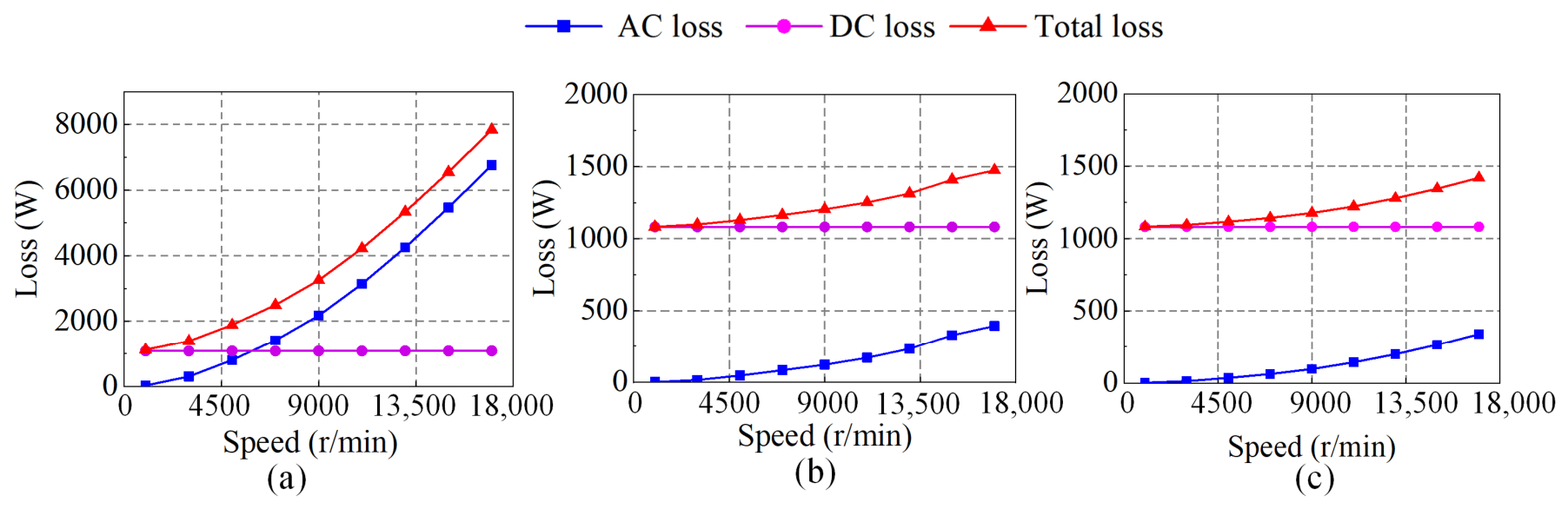
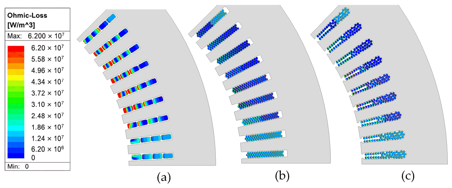
The loss characteristics of different winding types over a wide speed range are shown in Figure 1. The DC loss remains nearly constant with speed, whereas the AC loss increases continuously as the speed increases. For the round-wire and litz-wire windings, the DC loss is dominant over the entire speed range. By contrast, for the flat-wire winding, the AC loss becomes the dominant component when the speed exceeds 6000 r/min, indicating that additional winding losses are particularly pronounced under high-speed operating conditions. Figure 2 presents the AC loss distributions of the windings.
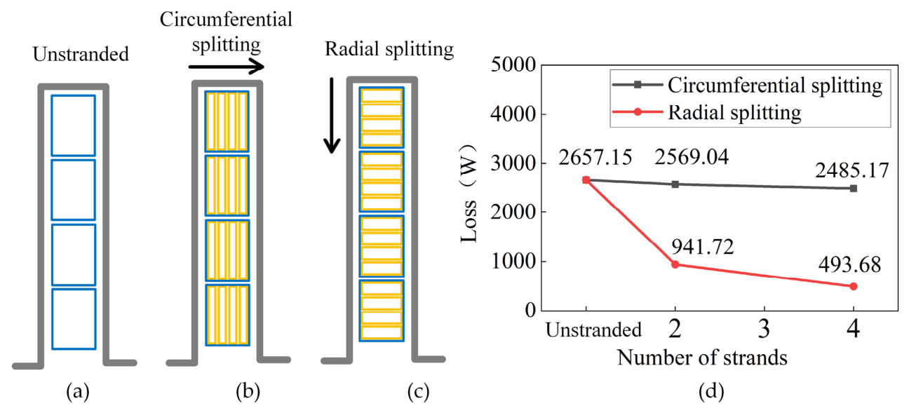
For a single-slot, four layer flat-wire winding, each large-cross-section conductor in a layer is further split into multiple thin flat-wire conductors connected in parallel. The conductors are split along either the circumferential or radial direction, and the corresponding loss comparison is shown in Figure 3. When circumferential splitting is adopted, the variation in loss is relatively small. In contrast, with radial splitting, the AC loss decreases significantly as the number of strands increases, indicating that radial splitting is more effective in suppressing AC loss. This is because the leakage flux passing through the stator slot has a larger circumferential component than radial component. When the conductor is split along the radial direction, the radial dimension of each strand is reduced and the eddy-current path becomes shorter, resulting in lower eddy-current loss.
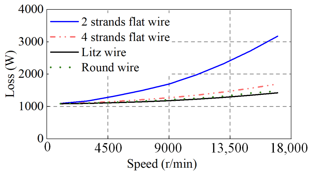
Radial splitting was implemented to form 2-strand and 4-strand parallel winding structures in order to investigate the effect of the number of conductor strands on winding loss characteristics. The results were also compared with motors using round-wire and litz-wire windings, as shown in Figure 4. The 2-strand parallel structure can reduce AC losses to some extent under high-speed operating conditions, but its loss level remains relatively high. In contrast, the 4-strand parallel structure exhibits a significant reduction in losses, and the overall loss trend approaches that of the round-wire and litz-wire windings. These results indicate that increasing the number of subdivided strands can effectively mitigate skin and proximity effects under high-frequency conditions and is thus an effective approach to reducing high-speed AC losses in continuous-wave flat-wire windings.
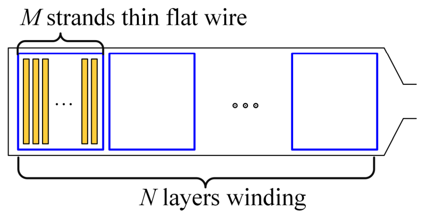
Conventional continuous-wave windings use a single continuous conductor that sequentially passes through multiple stator slots along the stator circumference. The coil end-windings are preformed and bent to achieve inter-slot connections, forming a continuous-wave shaped current path. Unlike traditional hairpin windings, the series connection between coils in such windings does not rely on end-welding; therefore, each phase typically retains only the incoming and outgoing terminals for external connections. Since multiple conductors are usually placed in each stator slot and previous analysis has shown that increasing the number of subdivided layers can significantly reduce winding losses, this paper proposes a multilayer thin flat-wire continuous-wave winding structure, as shown in Figure 5. Specifically, each original single-layer conductor is further subdivided into M individually insulated thin flat-wire strands connected in parallel to form an equivalent conductor, while the overall phase belt distribution, parallel branches, and turn-to-turn series connections of the winding are maintained unchanged.
Compared with conventional hairpin windings, the multilayer thin flat-wire continuous-wave winding can not only effectively reduce AC losses but also eliminate approximately 5–8 mm of straight welding-end length, thereby further reducing end-winding copper loss and shortening the axial length of the motor. Compared with round-wire windings, flat-wire windings have a more regular in-slot arrangement, which helps reduce parameter imbalance caused by the random distribution of conductors. Due to the randomness of conductor placement, the resistance and inductance imbalance of round-wire windings can typically exceed 8%, whereas that of flat-wire windings can be controlled at around 1%. In addition, round-wire windings contain more gaps between strands, resulting in discontinuous in-slot contact and heat-conduction paths; therefore, their heat dissipation performance is generally weaker than that of tightly arranged flat-wire windings. Compared with litz-wire windings, thin flat-wire windings can maintain high slot utilization while avoiding the increase in DC loss caused by conductor deformation and changes in the effective conductive cross-sectional area after compression forming. Moreover, the relatively thick main insulation of litz-wires occupies additional slot space, which is unfavorable for further improving the effective copper fill factor. Therefore, the multilayer thin flat-wire continuous-wave winding has comprehensive advantages in loss suppression, slot-space utilization, thermal performance, and manufacturing adaptability.

3. Eddy-Current Loss Model for Multilayer Thin Flat-Wire Windings

The eddy-current loss in the stator windings of permanent magnet synchronous motors primarily arises from two sources. The first is the additional loss caused by the skin effect due to the alternating current flowing through the conductors themselves. The second is the eddy-current loss induced by external alternating magnetic fields. These external fields mainly originate from the magnetic fields generated by the AC currents in adjacent conductors, as well as the alternating leakage flux within the slots resulting from the combined effects of the rotor permanent magnets and the slotting effect.

3.1. Winding Loss Model Under Stator Armature Field

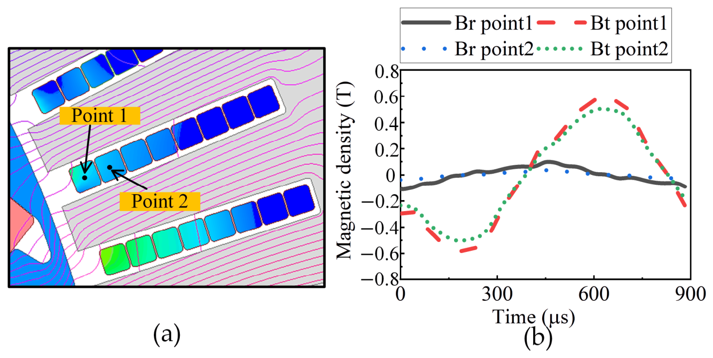
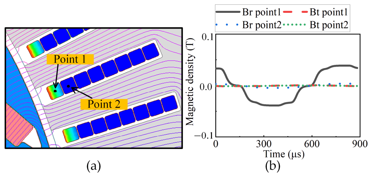
When only the stator armature magnetomotive force is applied, the magnetic field within the slot is predominantly tangential, as illustrated in Figure 6.
The following assumptions are made for the loss analysis of the stator winding:
(1)
The core permeability is assumed to be infinite;
(2)
The current in the conductor flows along the z-axis;
(3)
The magnetic vector potential exists only along the z-axis.
For a single conductor, its dimensions and the magnetic field intensity are shown in Figure 7.
Establishment of the 2D complex eddy-current equation of magnetic vector potential for a single conductor:
2 A ˙ z x 2 + 2 A ˙ z y 2 = k c 2 A ˙ z
where A ˙ z is the vector potential along the z-axis.
k c = 1 + j δ
δ = 2 w μ σ
where ω is the angular frequency, μ is the permeability, and σ is the conductivity of the copper conductor.
According to B = × A z z , the boundary condition at the conductor surface is:
A ˙ z y y = h c 2 = μ H ˙ x 1 A ˙ z y y = h c 2 = μ H ˙ x 2 A ˙ z x x = w c 2 = μ H ˙ y 1 A ˙ z x x = w c 2 = μ H ˙ y 2
According to the boundary conditions, the general solution of the z-axis of the magnetic vector potential is:
A ˙ z ( x , y ) = μ 2 k c H y 2 H y 1 cosh k c x sinh k c w c / 2 H y 2 + H y 1 sinh k c x cosh k c w c / 2 + H x 2 H x 1 cosh k c y sinh k c h c / 2 + H x 2 + H x 1 sinh k c y cosh k c h c / 2
The magnetic field components along the x and y-axis directions are:
H ˙ x = 1 μ A z y = 1 2 H x 2 H x 1 sinh k c y sinh k c h c / 2 + H x 2 + H x 1 cosh k c y cosh k c h c / 2
H ˙ y = 1 μ A z x = 1 2 H y 2 H y 1 sinh k c x sinh k c w c / 2 + H y 2 + H y 1 cosh k c x cosh k c w c / 2
According to × H ˙ = J ˙ , The current density along the z-axis is:
J ˙ z = H ˙ y x H ˙ x y = α y cosh k c x + β y sinh k c x α x cosh k c y + β x sinh k c y
where the coefficients are:
α x = k c 2 H ˙ x 2 H ˙ x 1 sinh k c h c / 2 ,   α y = k c 2 H ˙ y 2 H ˙ y 1 sinh k c w c / 2 β x = k c 2 H ˙ x 2 + H ˙ x 1 cosh k c h c / 2 ,   β y = k c 2 H ˙ y 2 + H ˙ y 1 cosh k c w c / 2
Based on the Poynting theorem, the electromagnetic power per unit length of the conductor can be expressed as:
P = 1 2 σ h c 2 h c 2 w c 2 w c 2 J ˙ z J ˙ z * d x d y

3.1.1. Single-Conductor Loss Model

For a single conductor, assuming infinite stator-core permeability, the boundary conditions in the y-axis are:
H ˙ y i x = ± w c 2 = 0               i = 1 , 2
According to Ampere’s circuital law, the boundary condition at the x-direction boundary of the conductor is:
H ˙ x 1 = 0 ,   H ˙ x 2 = I ˙ r w c
where I ˙ r denotes the current flowing through a single conductor. The corresponding winding loss can then be expressed as:
P = k c 2 I ˙ r 2 2 σ w c sinh ( k c h c ) 2 h c 2 h c 2 cosh k c y + h c 2 2 d y
Define the following parameters:
β = h c δ
Accordingly, (13) can be rewritten as:
P = I ˙ r 2 2 σ w c h c β sinh 2 β + sin 2 β cosh 2 β cos 2 β
Accordingly, the loss expression in (15) can be simplified to:
P = I r 2 2 σ w c h c ϕ β
Since this loss is induced by the current flowing within the conductor itself, it is defined as the skin-effect loss factor, as expressed in (17):
φ β = β sinh 2 β + sin 2 β cosh 2 β cos 2 β

3.1.2. Effect of In-Slot Conductor Arrangement

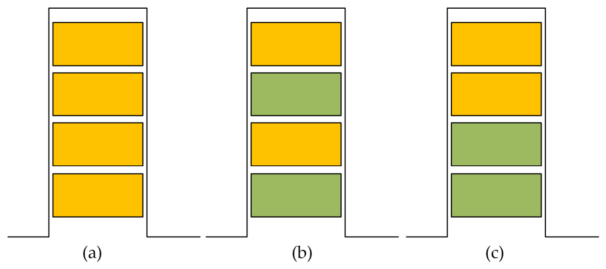
For different winding arrangements, the conductors within the same slot can be categorized into three configurations: Same-phase arrangement, different-phase staggered-layer arrangement, and different-phase grouped arrangement, as shown in Figure 8.
Each of the N s conductor layers in the slot is further split into M thin flat-wire strands. When the conductors within the slot are arranged in the same phase, H ˙ x 1 and H ˙ x 2 are in the same phase. According to Ampere’s circuital law, the magnetic field intensities at the upper and lower boundaries of the nth conductor strand, counted from the slot bottom, are given by:
H ˙ x 1 _ n = n 1 I ˙ r w c ,   H ˙ x 2 _ n = n I ˙ r w c
where
n = M s 1 + r
The loss of the nth conductor strand can then be expressed as:
P = I ˙ r 2 2 σ w c h c φ β + n n 1 ψ β
ψ β is defined as the proximity-effect loss factor, as given in (21):
ψ β = 2 β sinh β + sin β cosh β cos β
For a single slot containing N s M conductors, the total AC loss is given by:
P a c = 1 N s M P n
P a c = l e f I r 2 N s M σ h c w c φ β + N s 2 M 2 1 3 ψ β
When the conductors within the slot adopt a different-phase staggered-layer arrangement, the phase currents can be expressed as:
I ˙ 1 = I ˙ r e j γ 1 ,   I ˙ 2 = I ˙ r e j γ 2
The phase-angle difference between the two phase windings is:
Δ γ = ± 60
The current in the sth layer, counted from the slot opening to the slot bottom, is given by:
I ˙ s = I ˙ ( 1 ) , s = 1 , 3 , 5 I ˙ ( 2 ) , s = 2 , 4 , 6
where s = 1, 2, …, N s . The x-axis boundary conditions of the rth thin flat-wire strand in the sth layer are:
H x 1 s , r = 1 w c M v = 1 s 1 I ˙ v + r 1 I ˙ s ,   H x 2 s , r = 1 w c M v = 1 s 1 I ˙ v + r I ˙ s
In this case, the total winding loss within the slot is given by:
P a c = l e f N s M I ˙ r 2 σ w c h c φ β + 3 N s 2 + 1 M 2 4 12 ψ β ,   H x 2 s , r = 1 w c M v = 1 s 1 I ˙ v + r I ˙ s
For the different-phase grouped arrangement, each phase contains G conductor layers G = N s / 2 . When 1 s G , the x-axis boundary conditions of the conductor are:
H x 1 s , r = M s 1 + r 1 I ˙ 1 w c ,   H x 2 s , r = M s 1 + r I ˙ 1 w c
When G s N s , the x-axis boundary conditions of the conductor are:
H x 1 s , r = G M I ˙ 1 + M t 1 + r 1 I ˙ 2 w c ,   H x 2 s , r = G M I ˙ 1 + M t 1 + r I ˙ 2 w c
where t = 1, 2, …, G, t = sG.
P a c = l e f N s M I ˙ r 2 σ w c h c φ β + 13 N s 2 M 2 16 48 ψ β

3.1.3. Effect of Strand Number on Winding Losses

To quantitatively evaluate the AC-loss variation caused by conductor subdivision in each layer and compare different in-slot conductor arrangements, the relative loss factor K l o s s 1 r is defined as:
K l o s s 1 r = P a c r N s , M , f P a c r N s , 1 , f
where r represents the in-slot conductor arrangement. P a c r N s ,   M ,   f denotes the single-slot AC loss under the corresponding arrangement, while P a c r N s ,   1 ,   f represents the AC loss of the unsubdivided in-phase winding under the same N s and frequency conditions.
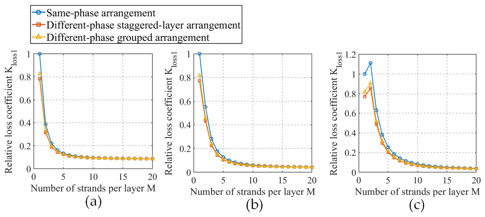
Under the condition that the total conductor height within the slot and the total current in each winding layer remain unchanged, the conductor height and current of a single-layer winding without subdivision are denoted as h 1 and I 1 , respectively. When the conductor is subdivided into M strands, the conductor height and current of each strand become h 1 / M and I 1 / M , respectively. Figure 9 shows the variation in the relative loss factor K l o s s 1 r with the strand number M for the three in-slot conductor arrangements at different frequencies. As M increases, the relative loss factors K l o s s 1 r of all three arrangements decrease overall. As M further increases, K l o s s 1 r the reduction rate gradually decreases, and the curves tend to become flatter. By comparing the three in-slot conductor arrangements, it can be observed that under the same N s ,   M ,   and   f , the AC loss is highest for the same-phase arrangement, followed by the different-phase grouped arrangement, while the different-phase staggered-layer arrangement exhibits the lowest AC loss. This is because in the same-phase arrangement there is the most pronounced proximity effect. In contrast, in the different-phase staggered-layer and different-phase grouped arrangements, phase-angle differences exist among the currents of different phases, which reduces the proximity-effect loss. Among them, the different-phase staggered-layer arrangement allows conductors carrying different-phase currents to be alternately distributed along the slot-depth direction and therefore exhibits the lowest relative loss coefficient. Under the 2000 Hz condition, a local peak appears near M = 2. This is because when M is small the suppression of the skin-effect loss coefficient caused by conductor thinning is not sufficient to offset the increase in the proximity-effect coefficient.
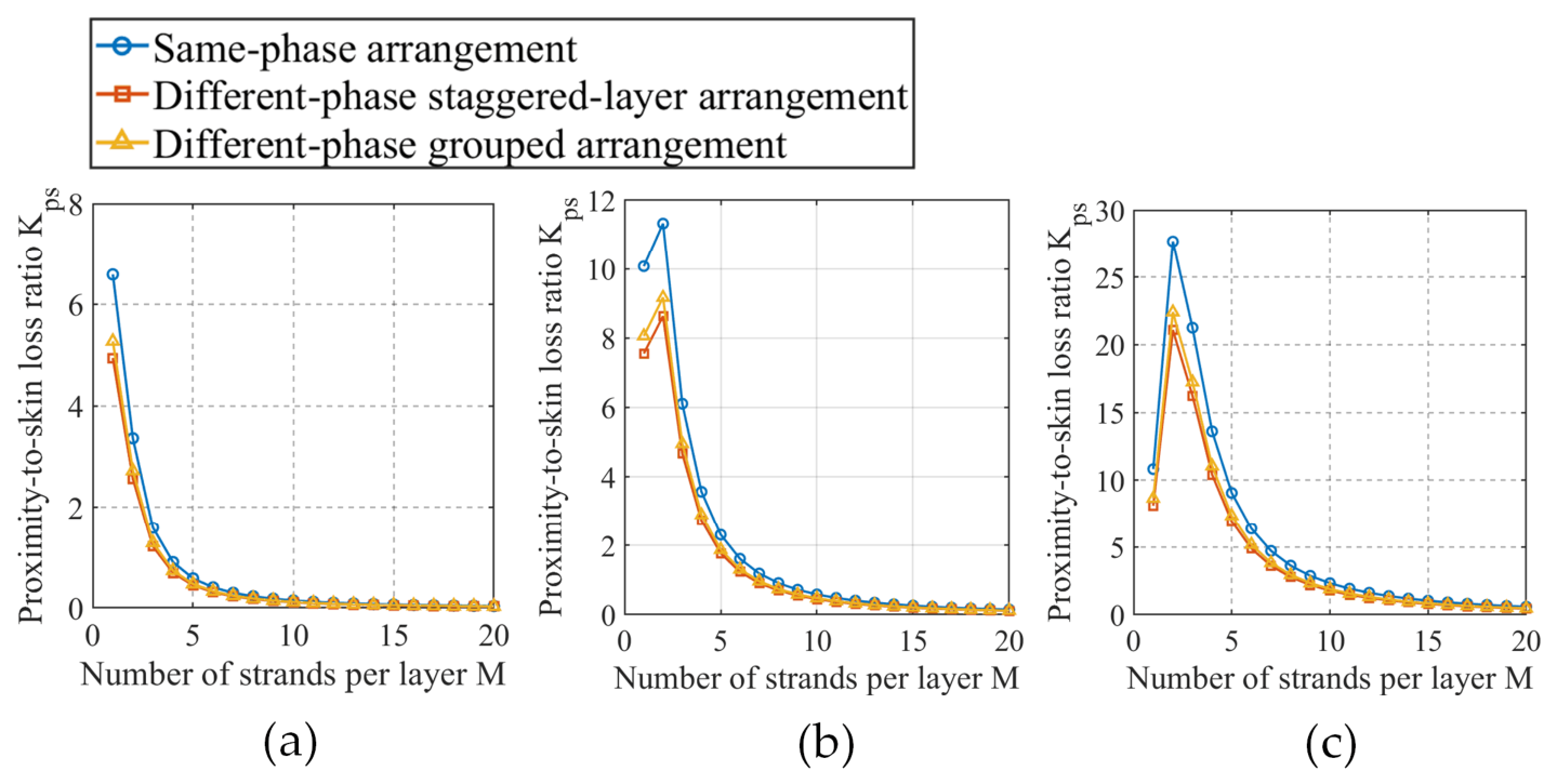
To quantitatively evaluate the relative dominance of proximity-effect loss over skin-effect loss, the proximity-to-skin loss ratio is defined as:
K p s r = P p r o x r N s , M , f P s k i n r N s , M , f
Figure 10 shows the variation in the proximity-to-skin loss ratio K p s r with the strand number M per layer at 500 Hz, 1000 Hz, and 2000 Hz. At 1000 Hz and 2000 Hz, the proximity-to-skin loss ratios for all three in-slot conductor arrangements first increase, then decrease rapidly, and gradually become stable as M increases. A local peak appears near M = 2, indicating that the proportion of proximity-effect loss relative to skin-effect loss reaches its maximum at this point.

3.1.4. Effect of Frequency on Winding Losses

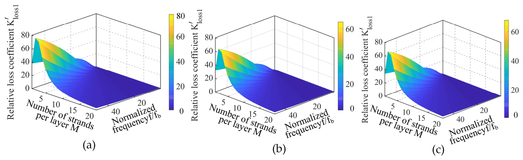
To characterize the variation in winding AC loss at different frequencies relative to the reference operating condition, a frequency-dependent AC loss factor is defined as:
K l o s s 1 r f = P a c r N s , M , f P a c r N s , 1 , f b
where f b is the reference frequency.
When the reference frequency f b is set to 100 Hz, the variations of the relative loss factor K l o s s 1 r with the normalized frequency f / f b and the strand number M per layer for the three winding arrangements are impacted, as shown in Figure 11. For the same strand number, the relative loss factor K l o s s 1 r increases significantly with frequency, especially when M is small. This is because an increase in frequency reduces the skin depth, resulting in a more nonuniform current distribution within the conductor and a stronger skin effect. Meanwhile, the proximity effect caused by the alternating leakage field within the slot is also intensified at higher frequencies, leading to a rapid increase in additional AC losses. In the region with larger M , the sensitivity to frequency variation decreases, and the surface gradually becomes flatter. By comparing the three winding arrangements, it can be observed that their frequency-response characteristics are generally consistent. The differences among the arrangements mainly arise from the proximity-effect factor, which is reflected in the different loss magnitudes.

3.1.5. Effect of Temperature on Winding Losses

The electrical conductivity of the winding varies with temperature and decreases as the temperature increases. The conductivity at temperature T is given by:
σ T = σ 20 1 + α T 20
where σ 20 is the electrical conductivity at 20 °C, in S/m, and α is the temperature coefficient of resistance of the copper winding.
K l o s s 1 r = P a c r N s , M , f , T P a c r N s , M , f , 20
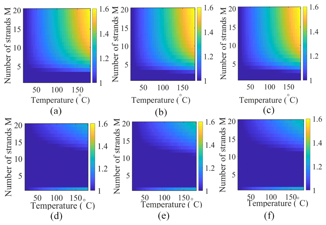
Figure 12 shows the effects of temperature and strand number M per layer on the relative loss factor K l o s s 1 r at 500 Hz and 2000 Hz. Under the 500 Hz condition, the relative loss factors of all three winding arrangements increase significantly with temperature, and the increase becomes more pronounced in the region with larger strand numbers. This is because, under low-frequency conditions, the skin and proximity effects are relatively weak, and the reduction in copper conductivity together with the increase in equivalent resistance caused by temperature rise become the dominant factors affecting the losses. As M increases, the thickness of each thin flat-wire strand decreases and the high-frequency additional losses are suppressed, making the temperature-induced loss increase more evident. By contrast, under the 2000 Hz condition, the overall variation in the relative loss factor K l o s s 1 r is relatively small. This is because the skin and proximity effects are much stronger at high frequencies, whereas the increase in temperature reduces the copper conductivity and increases the skin depth, thereby reducing β and weakening the additional losses caused by current crowding and external alternating magnetic fields. Therefore, under high-frequency conditions, the resistance-increase effect and the reduction in high-frequency additional losses partially offset each other, resulting in a smaller increase in the relative loss factor with temperature compared with the 500 Hz condition.
A comparison of the three in-slot conductor arrangements shows that the influence of temperature on the relative loss factor follows a generally similar trend. This is because temperature affects the losses mainly through the conductivity, skin depth, and the ϕ β and ψ β functions, which act through the same mechanism for all three arrangements. The different conductor arrangements mainly modify the proximity-effect factor; therefore, their influence is reflected primarily in local numerical differences rather than in substantial changes to the overall distribution pattern on the temperature–strand-number plane.

3.2. Winding Loss Model Under Rotor Field

The frozen-permeability method is used to solve for the case with only the rotor field, which mainly manifests as a radial magnetic field, as shown in Figure 13.
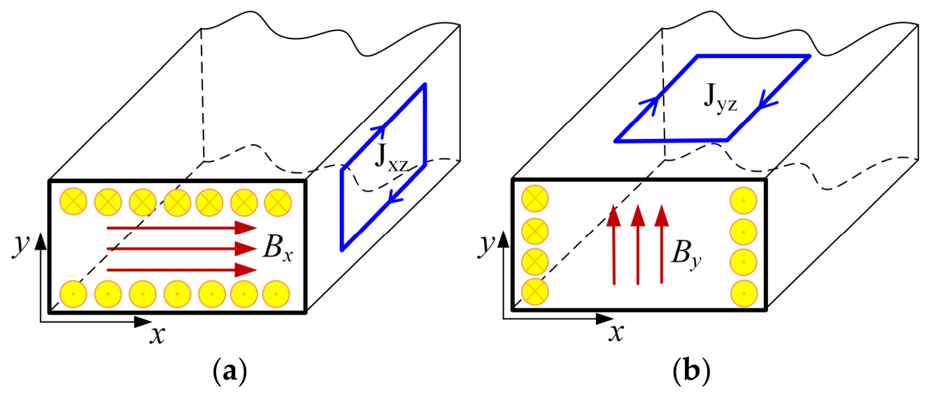
For a single conductor, the current density distribution and eddy currents under the radial and tangential magnetic field components are shown in Figure 14. The radial magnetic field component Bx drives the current toward the tangential sides, while the tangential component By causes the current to distribute along the radial direction. Assuming that the magnetic flux density is uniform along the axial direction, its rate of change can be equivalently expressed as the induced electromotive force generated in the winding:
E x z = 2 y l e f B x t ,   E y z = 2 x l e f B y t
The equivalent resistance of the eddy-current path can be expressed as:
R x z = 2 l e f σ c u w c d y ,   R x z = 2 l e f σ c u h c d x
Accordingly, the AC losses induced by the radial and tangential field components can be uniformly expressed as:
P e d d y = 0 h c 2 E x z 2 R x z + 0 w c 2 E y z 2 R y z = 1 12 w c l e f σ c u h c 3 B x t 2 + 1 12 h c l e f σ c u w c 3 B y t 2

4. FEA of Eddy-Current Losses in Multilayer Thin Flat-Wire Windings

4.1. Comparative Validation Between Analytical Method and FEA

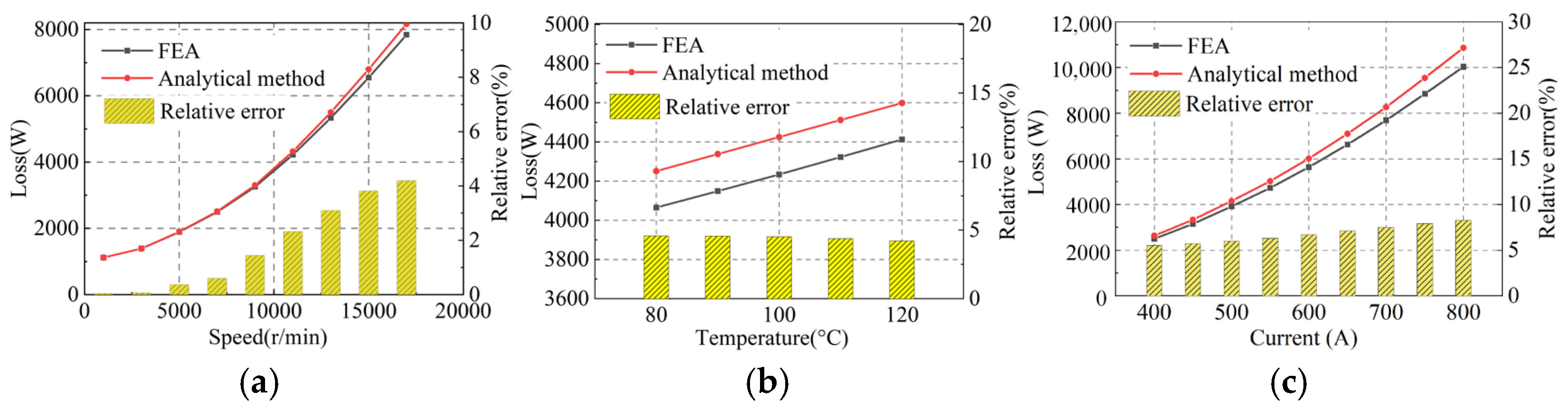
To verify the applicability of the established analytical model under different operating conditions, the winding losses calculated by the finite-element method and the analytical method are compared, as shown in Figure 15. Figure 15a presents the influence of speed on the winding loss. It can be seen that the loss variation trends obtained by the two methods are generally consistent, and the winding loss increases significantly with increasing speed. Over the entire speed range, the relative error between the analytical method and the finite-element method remains at a relatively low level, with a maximum error of 4.23%. As the speed increases, the relative error shows an increasing trend. This is mainly because the harmonic components in the slot become more pronounced under high-frequency operating conditions, and the slot leakage-field distribution becomes more complex. Therefore, the simplified magnetic-field distribution and boundary conditions adopted in the analytical model introduce certain deviations. Figure 15b shows the influence of temperature on the winding loss. Since the electrical conductivity of copper conductors is temperature-dependent, an increase in temperature changes the conductor resistance, skin depth, and high-frequency additional losses. The temperature-dependent conductivity is considered in the analytical model; therefore, the analytical results agree well with the finite-element results, with a maximum relative error of 4.58%. Figure 15c illustrates the influence of stator-core saturation on the winding-loss calculation under different load currents. In the analytical model, the permeability of the stator teeth is assumed to be infinite to simplify the magnetic boundary conditions in the slot. In contrast, the finite-element model adopts the nonlinear magnetization characteristics of the actual core material and can account for local saturation in the stator teeth and slot opening regions. As the load current increases, the local saturation of the stator teeth becomes more pronounced, leading to a decrease in the equivalent permeability and a change in the slot leakage-field distribution, which further affects the skin-effect and proximity-effect losses in the conductors. Therefore, the deviation between the analytical and finite-element results increases with increasing current, and the maximum relative error is 8.32%. Overall, the analytical model can effectively reflect the influence trends of speed, temperature, and load current on winding losses, and can be used for the rapid estimation and parameter trend analysis of AC losses in multilayer thin flat-wire windings.

4.2. Loss Characteristics with Different Strand Numbers

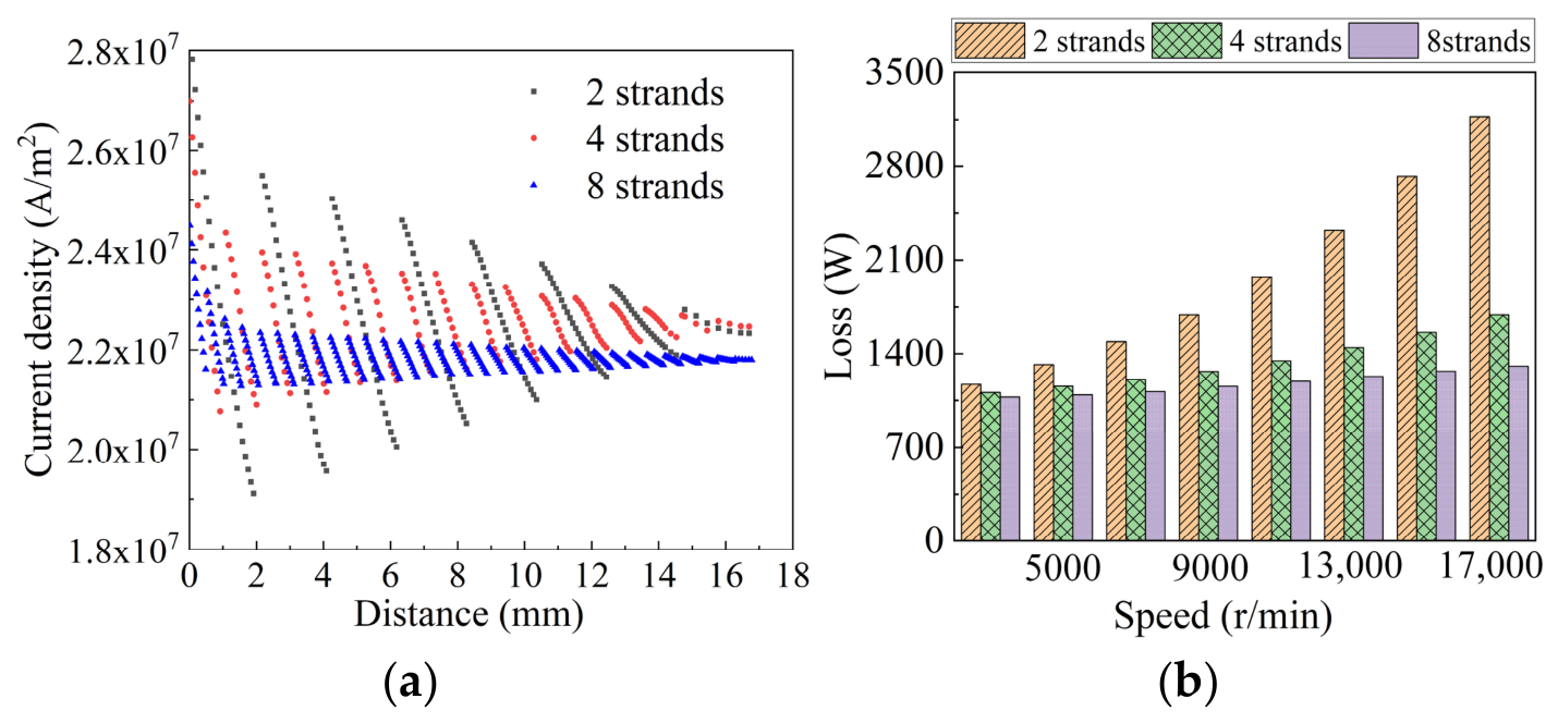
The current-density distributions of the winding layers for strand numbers M = 2, 4, and 8 are shown in Figure 16a, while Figure 16b presents the variation in loss with motor speed. The losses increase with speed for all cases; however, the growth rates differ significantly for different strand numbers. When M = 2, the thickness of each conductor strand remains relatively large, and the skin and proximity effects become significantly enhanced under high-speed operating conditions. As a result, the loss increases rapidly with speed and reaches a relatively high level in the high-speed region. When the strand number increases to M = 4 and M = 8, the loss growth trend is effectively suppressed.

4.3. Performance Comparison with Conventional Flat-Wire Windings

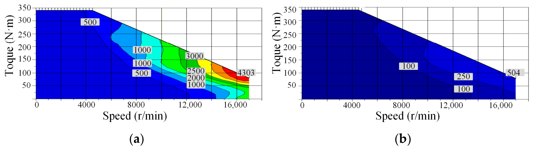
To further evaluate the loss reduction effect of the proposed multilayer thin flat-wire winding, two motor models with different winding configurations are compared under the same motor geometry and operating conditions. The conventional model adopts the unstranded flat-wire winding shown in Figure 3a, while the proposed model adopts the multilayer thin flat-wire winding shown in Figure 3c, where each conductor unit is radially subdivided into four thin flat-wire strands. The corresponding AC loss maps are presented in Figure 17. For the conventional unstranded flat-wire winding, the AC loss increases with speed, especially in the high-speed region, where the maximum loss reaches approximately 4303 W. In contrast, the proposed multilayer thin flat-wire winding exhibits much lower AC loss over the entire operating range, with a maximum value of approximately 504 W, corresponding to a reduction of 88.3%.
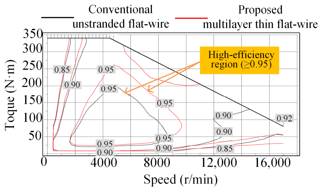
Figure 18 compares the efficiency maps of the conventional flat-wire winding and the proposed multilayer thin flat-wire winding. The black contour lines represent the conventional flat-wire winding, whereas the red contour lines represent the proposed multilayer thin flat-wire winding. The numerical labels on the contour lines indicate the corresponding efficiency values. It can be observed that, compared with the conventional flat-wire winding, the high-efficiency region above 95% extends further into the medium- and high-speed operating regions, and the efficiency degradation in the high-speed region becomes less pronounced. These results indicate that the proposed winding can effectively weaken eddy-current effects under high-frequency magnetic fields by reducing the characteristic dimension of each thin flat-wire strand, thereby reducing winding AC losses over a wide speed range and improving the overall operating efficiency of the motor.

5. Circulating-Current Loss Analysis and End-Winding Transposition of Multilayer Thin Flat-Wire Windings

5.1. Analysis of Circulating-Current Loss in Multilayer Thin Flat-Wire Windings

To reduce the winding thickness without changing the number of turns, a multi-strand thin flat-wire parallel structure is employed, where each turn consists of multiple parallel conductors. The rth strand in the sth layer and the jth strand in the tth layer from the slot opening to the slot bottom are expressed as:
l = ( s , r ) ,   ζ = ( t , j )
The voltage equations are established as follows:
R l i l + L l l d i l d t + l = 1 , l ζ N s M M l ζ d i l d t = U E l
where R l is the resistance of the l th sub-conductor, i l is the corresponding current, L l l is the self-inductance, M l ζ is the mutual inductance between the ζ th conductor and the l th conductor, and E l is the electromotive force induced in the l th conductor by the external alternating magnetic field. The self-inductance of a single conductor and the mutual inductance between strands are given by:
L l l = ψ l i l ,   M l ζ = ψ l ζ I l
The self-flux linkage and mutual flux linkage can be expressed as:
ψ l l = s l l B x y d x d y ,   ψ l ζ = s l ζ B x y d x d y
where S l l and S l ζ are the area of a single conductor and the flux-linkage area between the two conductors, respectively. The self-induced electromotive force is given by:
E l = 2 π f ψ l
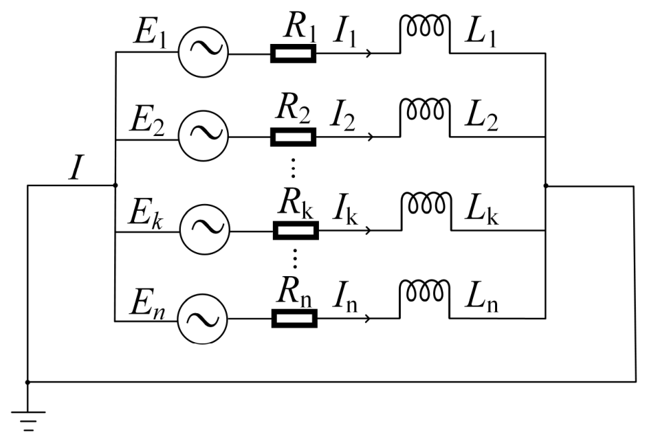
The circuit network topology of a single-turn, n-strand winding is shown in Figure 19, where i k represents the current flowing through the strand in the kth layer, and I is the total current of the single-turn winding. i a v denotes the average current of the n strand winding. The circulating-current and the corresponding circulating-current loss of each strand can therefore be expressed as:
i k c = i k i a v
P k c = 1 T 0 T i k c 2 R k d t

5.2. End-Winding Transposition Method for Multilayer Thin Flat-Wire Windings

Continuous-wave windings adopt a continuously formed structure and, unlike hairpin windings, do not require end-winding welding. As a result, they exhibit shorter end-winding lengths, which is beneficial for reducing end-winding losses and improving structural compactness. As discussed previously, the leakage magnetic field within the stator slot is nonuniform along the radial direction (i.e., the slot-depth direction), resulting in different magnetic-field intensities at different conductor positions. If parallel conductors are located in different magnetic-field regions, inconsistent induced electromotive forces will be generated, thereby causing circulating-current losses among the parallel branches. Therefore, in the design of continuous-wave windings, each parallel conductor should be distributed as uniformly as possible among different layer positions over the entire stator circumference. Meanwhile, from the perspective of practical implementation, winding layouts with interconnections within the same layer are preferred in order to simplify the manufacturing process.
For integer-slot windings, while maintaining branch balance, the number of slots occupied by each phase is Q/m. The number of slots passed through by each branch winding, i.e., a single conductor within one layer, is given by:
N k = Q m a
To quantitatively evaluate the capability of different transposition methods to suppress in-slot positional imbalance, a positional balance coefficient is defined. Let M be the number of parallel conductors and Nk be the number of slots passed through within one transposition period. The in-slot positions are divided into M positions from the slot opening to the slot bottom. Let nij denote the number of times that the ith parallel conductor occupies the jth slot-depth position within one transposition period. Ideally, each conductor should occupy each slot-depth position the same number of times, namely:
n i 1 = n i 2 = = n i M = N k M
Based on the above definition, the positional balance coefficient can be expressed as:
η p = 1 i = 1 M j = 1 M n i j N k M 2 M 1 N k 2
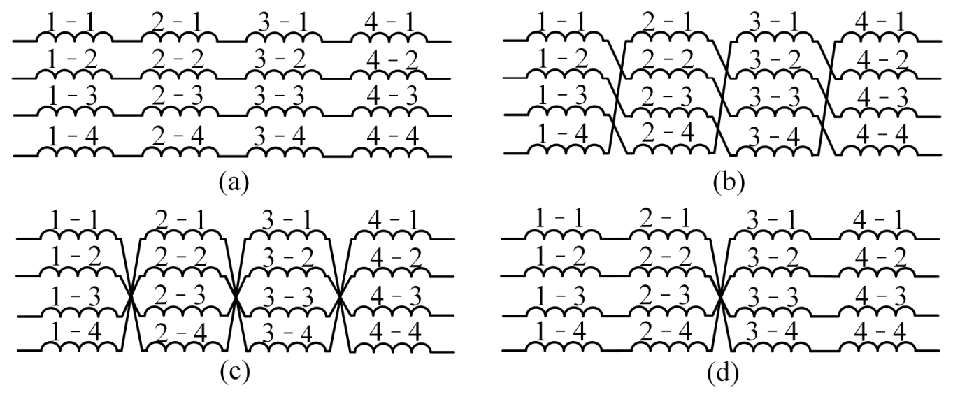
The closer η p is to 1, the more uniformly the parallel conductors occupy different slot-depth positions. When η p = 1, all conductors exhibit exactly the same positional distribution within one transposition period, indicating complete positional balance. When η p = 0, the positional distribution is the most uneven, making large induced electromotive-force differences and circulating-currents more likely to occur among conductors. Taking the case of four parallel conductors passing through four slots as an example, i.e., M = 4 and Nk = 4, the corresponding winding arrangement is shown in Figure 20. In the notation ab used in the figure, a represents the slot number and b represents the in-slot position.
For the non-transposed structure, each conductor always remains at a fixed slot-depth position, and the corresponding position occupancy matrix can be expressed as:
η p , a = 0
This result indicates that the non-transposed structure cannot balance the slot-depth positions experienced by the parallel conductors.
For the continuous flip transposition and intermittent flip transposition methods, each conductor switches only between two slot-depth positions rather than traversing all in-slot positions completely. For example, the position sequence of a conductor may be expressed as 1−4–1–4, 1–1–4–4. Since these transposition methods correspond to the same position occupancy counts, they yield the same positional balance coefficient, namely:
η p , c = η p , d = 2 3
This indicates that the above transposition methods can improve the conductor positional distribution to a certain extent, but complete positional balance still cannot be achieved.
Translation transposition enables each conductor to pass through all four slot-depth positions within four slots. For example, the position sequence of a conductor can be expressed as 1–2–3–4.
The relationship between the number of slots Nk passed through by a single winding within one layer and the strand number M is given by:
N k = λ M + r
where λ is an integer representing the number of complete traversals of all slot-depth positions by each parallel conductor within one transposition period, and r is the remainder representing the number of remaining slots after completing λ full positional cycles. When r = 0, each conductor can pass through all slot-depth positions completely and an equal number of times, thereby achieving complete positional balance. Therefore, the closer the remainder r is to 0 or M, the smaller the positional imbalance becomes; when r approaches M/2, the positional imbalance becomes relatively large.
For flip transposition, according to the value of Nk, the following cases can be classified:
(a)
When Nk < M, the number of slots within one transposition period is smaller than the number of parallel conductors. Therefore, each conductor cannot completely traverse all slot-depth positions, and complete positional balance cannot be achieved;
(b)
When Nk is an even number and is divisible by 4, intermittent flip transposition and continuous flip transposition can be adopted to achieve a balance between the numbers of positive-sequence and negative-sequence windings;
(c)
When Nk is even but not divisible by 4, continuous flip transposition and half-period flip transposition can be employed, as shown in Figure 21;
(d)
When Nk is odd, translation transposition can be adopted, whereas positional balance cannot be achieved through flip transposition.
For translation transposition, the possible cases can be classified as follows:
(a)
When λ ≥ 2, each conductor passes continuously through q slots at a certain position before shifting to the next position, thereby realizing intermittent translation transposition;
(b)
When λ = 1, continuous translation transposition can be adopted;
(c)
When λ = 0, complete positional balance can be achieved;
(d)
When λ ≠ 0, complete positional balance cannot be achieved.
The manufacturing complexity of translation transposition is significantly higher. Its end-winding structure must not only realize the interlayer positional shifting of conductors, but also ensure that the arrangement sequence, insulation clearance, and bending radius of multiple thin flat-wire conductors satisfy manufacturing requirements during the transposition process. Particularly when the number of parallel conductors is large, shifting a conductor from one slot-depth position to an adjacent position, or even from the bottom layer back to the top layer, introduces more complicated end-winding crossings and spatial clearance issues. This increases both the end-winding forming difficulty and the challenge of maintaining manufacturing consistency.
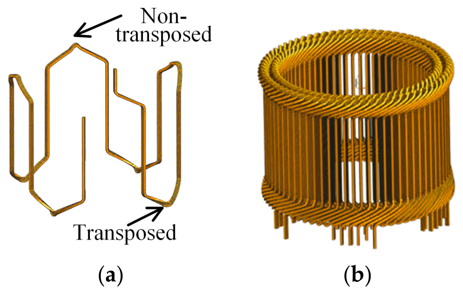
Intermittent transposition can reduce the number of end-winding crossings, thereby lowering the end-winding forming difficulty and insulation risk. It is suitable for windings with a relatively small number of parallel conductors. In addition, the intermittent transposition method can be implemented on only one side of the motor, making the winding arrangement and manufacturing process more convenient. The continuous-wave winding with intermittent transposition is shown in Figure 22.
Two motor models are established, and their main parameters are listed in Table 2. The stator winding of motor A adopts a 6-pole/54-slot configuration with six parallel branches and two parallel conductor strands. The stator winding of motor B adopts an 8-pole/96-slot configuration with four parallel branches and four parallel conductor strands.
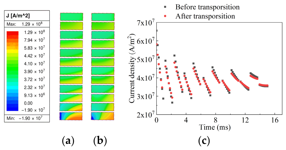
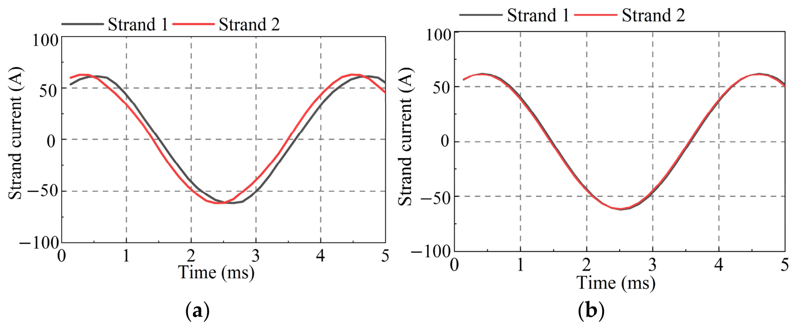
For motor A, Figure 23 shows the currents of the two parallel conductors in phase A before transposition. Differences in both amplitude and phase can be observed between the two conductor currents, with a maximum instantaneous current difference of 2.21 A. According to Equation (46), the corresponding circulating-current loss is 1.8 W. After flip transposition, the positional balance coefficient reaches 8/9. The post-transposition currents are shown in Figure 23b, where the current difference is almost eliminated. Figure 24 presents the winding current-density distributions before and after transposition. Before transposition, the current density exhibits large fluctuations and distinct local high-current-density regions. After transposition, the overall distribution becomes more concentrated and smoother. These results indicate that end-winding transposition can effectively balance the current distribution among parallel conductors and reduce local current concentration, thereby helping to reduce additional AC losses.
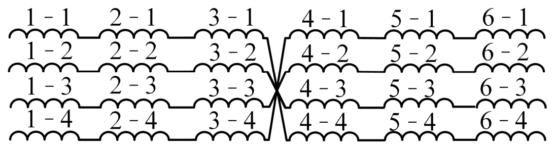
For motor B, the branches are uniformly distributed among different slots and winding layers to avoid circulating-currents between branches. A single branch sequentially passes through eight magnetic poles to form one winding cycle before entering the next cycle. When a six-layer winding structure is adopted, each branch passes through two layers within one winding cycle. Therefore, the intermittent end-winding transposition continuous-wave winding structure shown in Figure 22 is adopted, and its winding connection is illustrated in Figure 25. Before transposition, the same strand remains at the same in-slot position. After transposition, the strand is transferred from its original position to the symmetric position in the same layer through the end-winding connection.
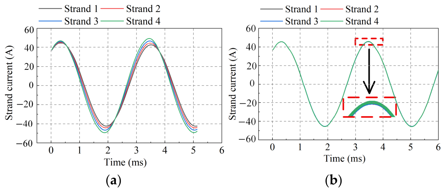
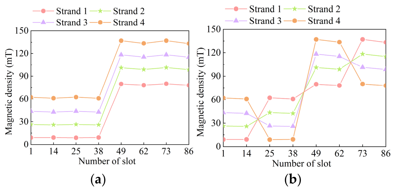
At a speed of 4775 r/min and a phase-current RMS value of 520 A, Figure 26a shows the current distribution of the parallel strands before transposition. Both the current magnitude and phase are unbalanced among the parallel strands. This is because different strands are located at different in-slot positions and therefore experience different leakage-field environments. After adopting the intermittent end-winding transposition, the leakage-field exposure of different strands becomes more balanced, as shown in Figure 27. Although the position balance coefficient of the proposed transposition method is only 2/3, the strand current distributions are almost consistent, as shown in Figure 26b, indicating that this transposition method can effectively suppress the circulating-current among parallel strands.
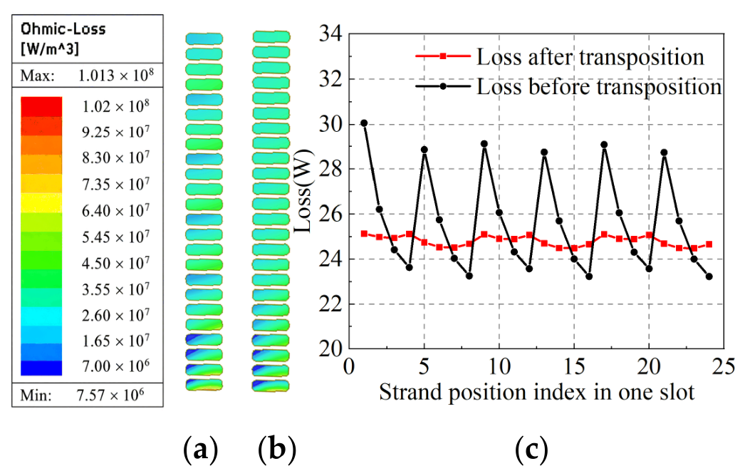
Figure 28 shows the single-slot winding loss distribution before and after transposition. The winding loss distribution among different layers becomes more uniform after transposition, and the total winding loss is lower than that of the non-transposed structure. This indicates that the proposed intermittent end-winding transposition method can not only improve the current balance among parallel strands, but also further reduce the additional losses caused by inter-strand circulating-currents. Table 3 compares the current difference among parallel strands and the winding losses before and after transposition. After transposition, the circulating-current loss is significantly reduced, and the total winding loss decreases accordingly.
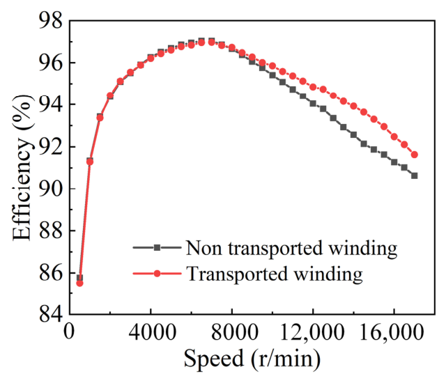
At the same torque, the efficiency at different speeds are shown in Figure 29. In the high-speed region, the efficiency after transposition are higher than before transposition.
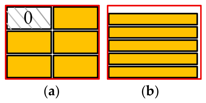
Existing in-slot transposition methods usually reduce eddy-current losses and circulating-current losses by crossing multiple conductors within the slot [20,21]. However, such methods require a certain amount of transposition space to be reserved inside the slot. As shown in Figure 30a, the position marked as 0 represents a vacant conductor position, which reduces the slot-space utilization. In contrast, the multilayer thin flat-wire winding and end-winding transposition methods proposed in this paper do not require any vacant transposition inside the slot, as shown in Figure 30b. Taking a winding with a single-strand size of 5 mm × 2.5 mm and a single-side insulation thickness of 0.075 mm as an example the in-slot occupied areas of the two schemes are estimated. The in-slot occupied area of the proposed scheme is approximately 86.34% of that of the method reported in the literature. Therefore, while maintaining a comparable eddy-current loss suppression effect and improving the current balance among parallel strands, the proposed end-winding transposition method avoids the occupation of effective slot space caused by in-slot transposition, which is beneficial for improving slot-space utilization and engineering manufacturability.

6. Experimental Validation

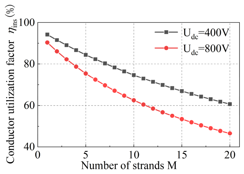
For multilayer thin flat-wire parallel windings, reducing the characteristic dimensions of each conductor is beneficial for suppressing high-frequency AC losses. However, conductor subdivision also introduces additional insulation-occupied areas. The insulation thickness of a single conductor is mainly determined by the motor voltage level, insulation withstand requirements, and manufacturing process. For 400 V electric drive systems, the single-side insulation thickness is typically 0.075 mm, whereas for 800 V electric drive systems, it can increase to 0.13 mm. When an original single-layer conductor is subdivided into multiple thin flat-wire strands, the insulation proportion within the slot increases, resulting in a reduction in the net copper slot fill factor. Therefore, while multilayer thin flat-wire windings can reduce AC losses, a tradeoff between AC loss suppression capability and slot fill factor must be considered in the winding design. Assuming that the single-side insulation thickness of each thin flat-wire conductor is t i n s , the net copper slot fill factor of the Ns-layer and M-strand winding can be defined as:
k C u M = N s M w c h c A s l o t
The total slot fill factor including conductor insulation:
k t o t M = N s M w c + 2 t i n s h c + 2 t i n s A s l o t
The conductor utilization factor is defined as:
η i n s = k C u N s M k t o t N s M = w c h c w c + 2 t i n s h c + 2 t i n s
The conductor utilization factor corresponding to different numbers of turns are shown in the Figure 31.
Table 4 compares the slot fill factor, conductor utilization factor, and winding loss. Under the condition of the same net copper slot fill factor, the conductor utilization factor of the 4-strand thin flat-wire winding decreases 12.7% due to the increased proportion of inter-strand insulation. However, the winding loss decreases 41.96%. This indicates that proper strand subdivision can significantly reduce winding loss at the cost of a certain amount of insulation space.
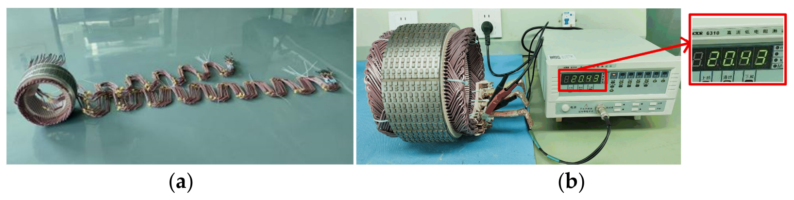
The proposed intermittent end-winding transposition continuous-wave winding can be realized using dedicated forming fixtures. The end-winding bending fixture mainly consists of a base plate, guide grooves, clamping blocks, and limiting structures. It is used to fix the thin flat-wires and constrain their bending path, bending radius, and strand spacing, thereby ensuring consistent end-winding forming and reducing the risk of insulation damage. The flipping fixture consists of flipping guide plates, guide notches, and limiting edges, which guide the parallel strands to complete position exchange in the end-winding region. Based on the above forming process, the prototype of the intermittent end-winding transposition continuous-wave winding was fabricated, as shown in Figure 32a. To verify the connection reliability and resistance consistency of the winding, the winding resistance of the prototype was measured using a DC resistance tester, as shown in Figure 32b.
This process does not change the in-slot conductor arrangement or occupy effective slot space. In mass production, it can be further automated using dedicated molds and clamping mechanisms. Compared with conventional hairpin windings, the proposed multilayer thin flat-wire continuous-wave winding has a simplified manufacturing process. Conventional hairpin windings generally require multiple processes, such as conductor preforming, insertion, end-winding expansion, twisting, terminal cutting, welding, weld inspection, and rework. In contrast, although the continuous-wave winding introduces an additional local end-winding flipping process, it reduces the insertion of separate conductors and a large number of end-winding welding operations, thereby reducing the number of connection points and the difficulty of weld-quality consistency control. Therefore, the proposed winding structure offers good engineering manufacturability while maintaining low-loss performance.
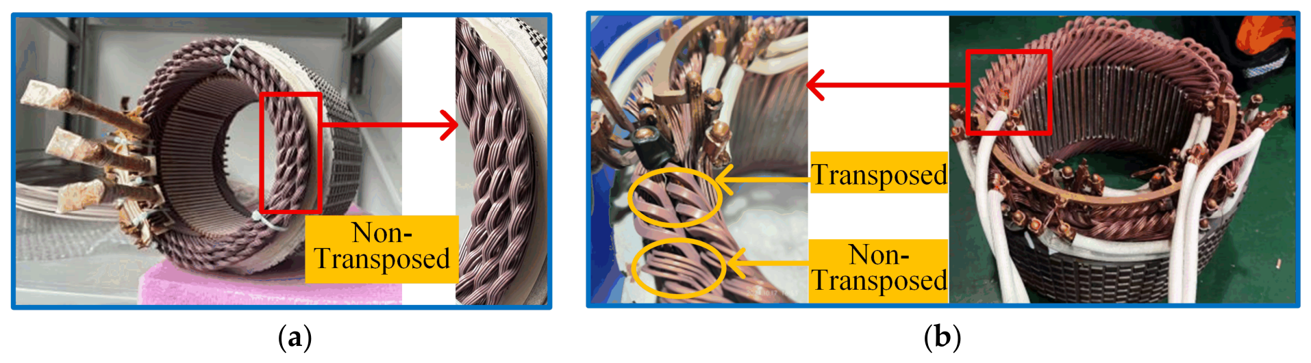
To verify the feasibility and effectiveness of the proposed multilayer thin flat-wire winding structure and end-winding transposition method, two prototypes were developed and experimentally tested. One prototype adopts the multilayer thin flat-wire winding without transposition, as shown in Figure 33a. The other prototype adopts the same multilayer thin flat-wire winding structure, but the intermittent end-winding transposition method shown in Figure 25 is applied. Therefore, both non-transposed and transposed end-winding connection forms can be observed in this prototype, as shown in Figure 33b. The enlarged view further illustrates the winding connection and strand transposition arrangement. Except for the end-winding transposition scheme, the two prototypes have identical main electromagnetic structural parameters, ensuring a fair comparison of the experimental results.
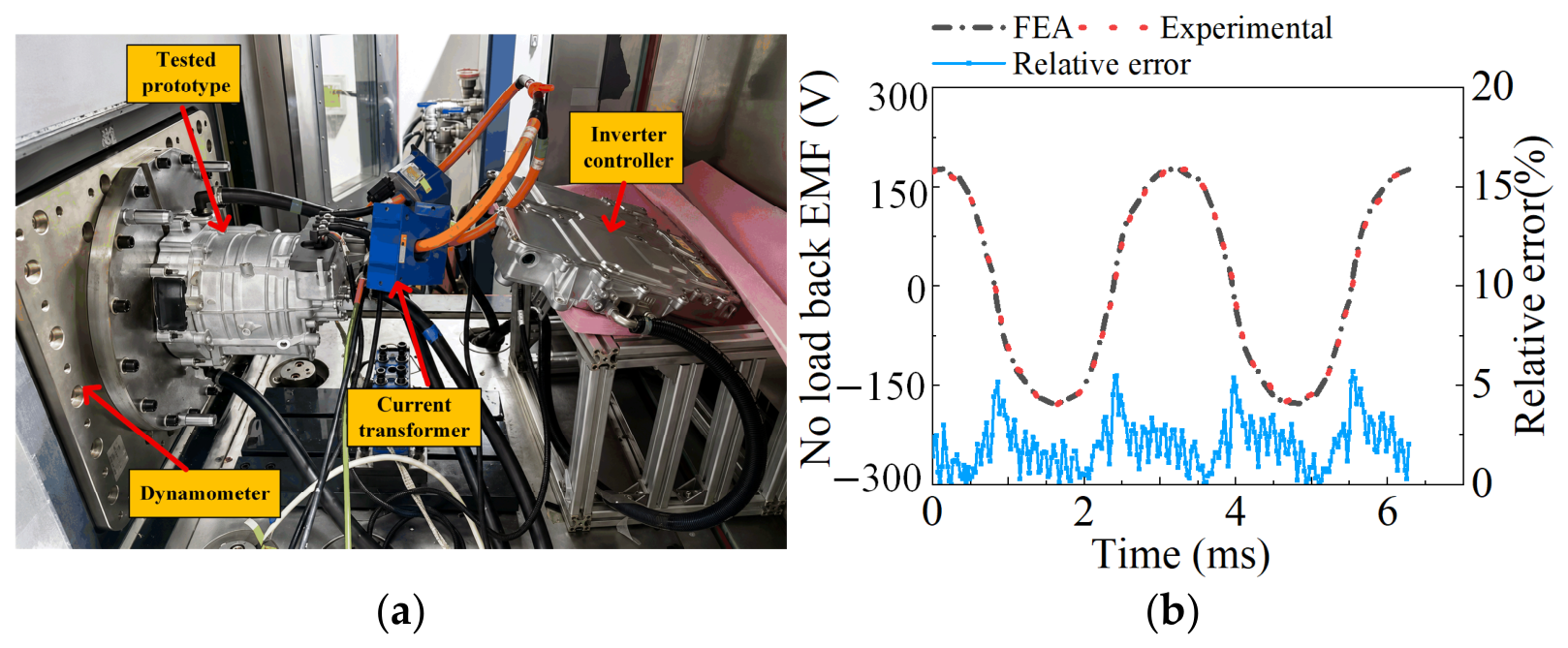
The prototype test platform is shown in Figure 34a. The controller is used to control the load variation, and the current transformer is used to measure the output current of the controller. The no-load back electromotive force (back-EMF) of the prototype motor was measured. The initial temperature was 25 °C, and the motor was driven by a dynamometer to operate under no-load conditions at 4775 r/min. The measured results were compared with the FEA results, as shown in Figure 34b. The relative error is defined by Equation (56). The maximum relative error is 5.69%. The experimentally measured no-load back-EMF waveform agrees well with the FEA result. This indicates that the established finite-element model can accurately reflect the actual electromagnetic characteristics of the motor and can be used for the subsequent analysis of winding losses and efficiency characteristics.
ε t = e e x p t e f e a t e e x p t × 100 %
where e exp t is the experimentally measured no-load back-EMF, and e f e a t is the no-load back-EMF obtained from FEA.
Efficiency point tests were carried out on the two prototypes, as shown in Figure 33, and the corresponding efficiency maps are presented in Figure 35. The black contour lines represent the motor without transposition, whereas the red contour lines represent the motor with intermittent end-winding transposition. The contour labels indicate the corresponding efficiency values. Compared with the motor without transposition, the efficiency contours of the motor with intermittent end-winding transposition expand outward overall. In particular, the high-efficiency regions above 95.5% and 96.5% are significantly enlarged, indicating that the proposed end-winding transposition method enables the motor to maintain high efficiency over a wider speed and torque range. This improvement is more pronounced in the medium- and high-speed regions. This is mainly because, as the speed increases, the winding AC loss and inter-strand circulating-current loss gradually increase. The end-winding transposition reduces the induced electromotive-force imbalance among strands and effectively suppresses circulating-current losses and additional AC losses.

7. Conclusions and Perspectives

This paper proposes a multilayer thin flat-wire continuous-wave winding and an intermittent end-winding transposition method to reduce AC winding losses.
The analytical results show that the in-slot conductor arrangement, strand number, frequency, and temperature all affect the AC loss of the multilayer thin flat-wire winding. The FEA results show that, compared with the conventional flat-wire winding, the multilayer thin flat-wire winding can reduce the winding loss by up to approximately 88.3%. In addition, the multilayer thin flat-wire winding can expand the high-efficiency region in the medium- and high-speed ranges. After multiple thin flat-wire strands are connected in parallel, unbalanced induced electromotive forces and circulating-current losses occur among the strands. The proposed intermittent end-winding transposition method enables the periodic positional balancing of parallel conductors among different slot-depth positions, thereby reducing winding losses. Proper strand subdivision and end-winding transposition design can achieve effective loss suppression without significantly reducing slot-space utilization, while maintaining good manufacturing feasibility. Prototype samples were further fabricated and experimentally tested. The comparison of no-load back-EMF results shows that the established finite-element model can accurately reflect the actual electromagnetic characteristics of the motor. The efficiency-map test results indicate that the end-winding transposition can effectively reduce circulating-current losses and additional AC losses in the multilayer thin flat-wire winding, thereby improving the operating efficiency of the motor. In summary, the proposed multilayer thin flat-wire continuous-wave winding features smaller individual strand dimensions, a more compact in-slot arrangement, and fewer end-winding welding joints. It can effectively reduce the winding AC losses of high-speed permanent magnet synchronous motors while maintaining high copper utilization and good engineering manufacturability. The end-winding transposition method further improves the current balance among parallel strands, providing a feasible low-loss winding design for high-power-density electric vehicle traction motors.
In future work, the three-dimensional leakage magnetic field in the end-winding region, conductor bending, and end-loss variation caused by end-winding transposition will be further considered, and corresponding corrections will be introduced to improve the accuracy of the analytical model. In addition, quantitative comparisons between the proposed method and existing segmented windings, in-slot transposed windings, and other schemes can be further conducted on the same motor platform and under identical operating conditions, so as to systematically evaluate their loss suppression performance, slot-space utilization, and engineering manufacturability.

Author Contributions

Conceptualization, S.Z., X.Z., A.L. and B.Z.; methodology, S.Z. and X.Z.; software, S.Z.; validation, S.Z., A.L., Y.C. and D.L.; formal analysis, S.Z., A.L. and B.Z.; investigation, S.Z., Y.C. and D.L.; resources, X.Z., Y.C. and D.L.; data curation, S.Z. and Y.C.; writing—original draft preparation, S.Z.; writing—review and editing, X.Z., A.L. and B.Z.; visualization, S.Z.; supervision, A.L. and B.Z.; project administration, A.L. and B.Z.; funding acquisition, B.Z. All authors have read and agreed to the published version of the manuscript.

Funding

This study was supported by the National Natural Science Foundation of China (No. 52377062).

Data Availability Statement

The datasets generated and analyzed during the current study are available from the corresponding author on reasonable request.

Conflicts of Interest

Author Xiaoting Zhang was employed by the company Xiamen Tungsten Co., Ltd. Authors Yongpeng Cao and Decai Liu were employed by the company Chongqing Tsingshan Industrial Co., Ltd. The remaining authors declare that the research was conducted in the absence of any commercial or financial relationships that could be construed as a potential conflict of interest.

References

  1. Su, Y.; Zhao, J.; An, G.; Jin, W.; Li, S.; Nie, Y.; Xu, G. An overview of recent advances in the online temperature estimation of PMSM in electric vehicle applications. Electronics 2026, 15, 1249. [Google Scholar] [CrossRef]
  2. Chen, M.; Huang, L.; Yang, H.; Yang, J.; Zhu, Z.; Li, Y. Thrust generation mechanism of a hybrid excitation field modulated transverse flux linear generator by magnetic field modulation theory. IEEE Trans. Ind. Electron. 2026, 73, 9716–9728. [Google Scholar] [CrossRef]
  3. Pang, Y.; Jin, S.; Jin, W.; Yu, S. Open winding-permanent magnet/magnet reluctance hybrid rotor double stator synchronous motor SVPWM control. CES Trans. Electr. Mach. Syst. 2024, 8, 426–435. [Google Scholar] [CrossRef]
  4. Soltani, M.; Nuzzo, S.; Barater, D.; Franceschini, G. A multi-objective design optimization for a permanent magnet synchronous machine with hairpin winding intended for transport applications. Electronics 2021, 10, 3162. [Google Scholar] [CrossRef]
  5. Zou, T.; Gerada, D.; Rocca, A.L.; Moslemin, M.; Cairns, A.; Cui, M. A comprehensive design guideline of hairpin windings for high power density electric vehicle traction motors. IEEE Trans. Transp. Electrif. 2022, 8, 3578–3593. [Google Scholar] [CrossRef]
  6. Chen, M.; Huang, L.; Yang, H.; Yang, J.; Zhou, Z.; Li, Y. Design and analysis of a hybrid excitation transverse flux linear machine used for linear railway traction. IEEE Trans. Transp. Electrif. 2025, 12, 2743–2759. [Google Scholar] [CrossRef]
  7. Park, S.H.; Chin, J.W.; Cha, K.S.; Ryu, J.Y.; Lim, M.S. Investigation of AC copper loss considering effect of field and armature excitation on IPMSM with hairpin winding. IEEE Trans. Ind. Electron. 2023, 70, 12102–12112. [Google Scholar] [CrossRef]
  8. Yan, Y.; Mao, C.; Li, C.; Ren, H. Analysis and optimization of the winding loss of flat-wire motors. Electronics 2024, 13, 3115. [Google Scholar] [CrossRef]
  9. Ju, X.; Cheng, Y.; Du, B.; Yang, M.; Yang, D.; Cui, S. AC loss analysis and measurement of a hybrid transposed hairpin winding for EV traction machines. IEEE Trans. Ind. Electron. 2022, 70, 3525–3536. [Google Scholar] [CrossRef]
  10. Yang, P.; Liang, Y.; Liu, J.; Zhang, K. AC losses calculation of parallel multi-strand flat wire windings for automotive drive motor. IET Electr. Power Appl. 2024, 18, 116–127. [Google Scholar] [CrossRef]
  11. Zhu, S.; Paciura, K.; Barden, R. Design approach of hairpin winding motor with high parallel path numbers. In Proceedings of the IEEE Energy Conversion Congress and Exposition (ECCE), Vancouver, BC, Canada, 10–14 October 2021; pp. 4534–4538. [Google Scholar] [CrossRef]
  12. Preci, E.; Nuzzo, S.; Valente, G.; Gerada, D.; Barater, D.; Degano, M. Segmented hairpin topology for reduced losses at high-frequency operations. IEEE Trans. Transp. Electrif. 2021, 8, 688–698. [Google Scholar] [CrossRef]
  13. Wang, D.; Liang, Y.; Gao, L.; Bian, X.; Wang, C. A new global transposition method of stator winding and its loss calculation in AC machines. IEEE Trans. Energy Convers. 2019, 35, 149–156. [Google Scholar] [CrossRef]
  14. Zhang, J.; Zhang, Z.; Xia, Y.; Yu, L. Thermal analysis and management for doubly salient brushless DC generator with flat wire winding. IEEE Trans. Energy Convers. 2020, 35, 1110–1119. [Google Scholar] [CrossRef]
  15. Fan, X.; Li, D.; Qu, R.; Wang, C.; Li, J. Hybrid rectangular bar wave windings to minimize winding losses of permanent magnet machines for EV/HEVs over a driving cycle. In Proceedings of the IEEE International Magnetics Conference (INTERMAG), Singapore, 23–27 April 2018. [Google Scholar] [CrossRef]
  16. Zhang, J.; Jiang, H.; Zhang, Z.; Yu, L.; Zhu, X. AC loss analytic method and optimization of litz winding for high-speed electrical machines. IEEE Trans. Ind. Electron. 2023, 71, 3330–3341. [Google Scholar] [CrossRef]
  17. Liu, H.; Lee, M. Design analysis of an interior permanent magnet synchronous motor with hybrid hair-pin and litz wire windings. Electronics 2025, 14, 3350. [Google Scholar] [CrossRef]
  18. Zhang, L.; Liang, Y. A new four-row integral transposition method of stator windings and circulating current loss reduction in large turbo generators. IET Electr. Power Appl. 2023, 17, 124–133. [Google Scholar] [CrossRef]
  19. Zhou, Y.; Su, H.; Yu, S.; Xiong, Q.; Li, R.; Geng, P.; Lei, B.; Leng, F. Equivalent study on mechanical parameters of roebel transposed wire used in an HTS machine. IEEE Trans. Appl. Supercond. 2024, 34, 6900305. [Google Scholar] [CrossRef]
  20. Liu, J.; Liang, Y.; Yang, P. Research on novel flat wire transposed winding of PMSM for electric vehicle. IEEE Trans. Transp. Electrif. 2022, 9, 771–781. [Google Scholar] [CrossRef]
  21. Wang, D.; Liang, Y.; Gao, L.; Wang, C.; Bian, X. Research on transposition method and loss of multi-turn coil in an induction motor. IEEE Trans. Magn. 2019, 55, 7501604. [Google Scholar] [CrossRef]
Figure 1. Comparison of losses in different winding configurations. (a) Flat-wire winding; (b) litz-wire winding; (c) round-wire winding.
Electronics 15 02665 g001
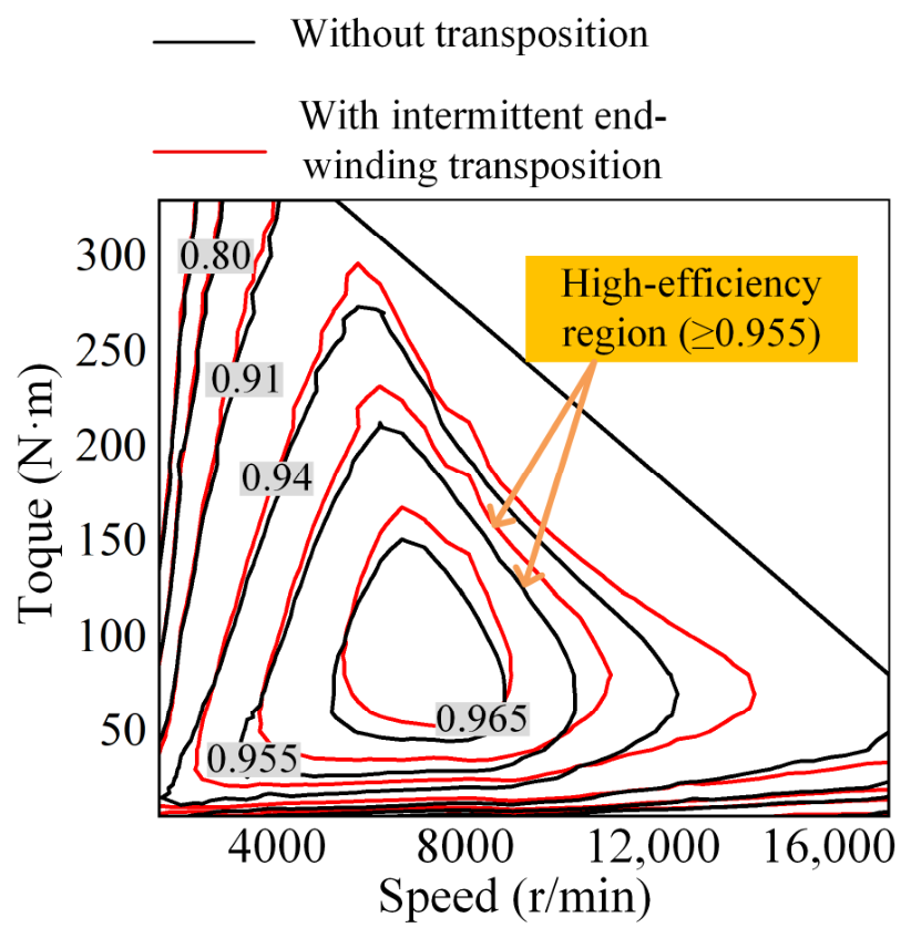
Figure 2. Distribution of losses in different winding configurations. (a) Flat-wire winding; (b) litz-wire winding; (c) round-wire winding.
Electronics 15 02665 g002
Figure 3. Effect of splitting direction and strand number on winding loss. (a) Unstranded; (b) circumferential splitting; (c) radial splitting; (d) loss comparison under different splitting directions.
Electronics 15 02665 g003
Figure 4. Comparison of winding losses for different winding types and strand numbers.
Electronics 15 02665 g004
Figure 5. Multilayer thin flat-wire windings.
Electronics 15 02665 g005
Figure 6. Radial and tangential flux density components at different positions in the stator slot. (a) Selected observation points; (b) magnetic flux density waveforms.
Electronics 15 02665 g006
Figure 7. The boundary conditions and dimensions of a single conductor.
Electronics 15 02665 g007
Figure 8. Arrangement Configurations of Conductors. (a) Same-phase arrangement; (b) different-phase staggered-layer arrangement; (c) different-phase grouped arrangement.
Electronics 15 02665 g008
Figure 9. Variation in relative loss coefficient with strand number under different frequencies and in-slot conductor arrangements. (a) 500 Hz; (b) 1000 Hz; (c) 2000 Hz.
Electronics 15 02665 g009
Figure 10. Variation in proximity-to-skin loss ratio with strand number under different frequencies and in-slot conductor arrangements. (a) 500 Hz; (b) 1000 Hz; (c) 2000 Hz.
Electronics 15 02665 g010
Figure 11. Variation in frequency-dependent relative loss coefficient with normalized frequency and strand number under different in-slot conductor arrangements. (a) Same-phase arrangement; (b) different-phase staggered-layer arrangement; (c) different-phase grouped arrangement.
Electronics 15 02665 g011
Figure 12. Variation in temperature-dependent relative loss coefficient with temperature and strand number under different frequencies and in-slot conductor arrangements. (a) Same-phase arrangement at 500 Hz; (b) different-phase staggered-layer arrangement at 500 Hz; (c) different-phase grouped arrangement at 500 Hz; (d) same-phase arrangement at 2000 Hz; (e) different-phase staggered-layer arrangement at 2000 Hz; (f) different-phase grouped arrangement at 2000 Hz.
Electronics 15 02665 g012
Figure 13. Radial and tangential flux density components at different positions in the stator slot. (a) Selected observation points; (b) magnetic flux density waveforms.
Electronics 15 02665 g013
Figure 14. Schematic of eddy-current paths induced by different magnetic-field components in a single conductor. (a) Eddy-current path induced by the Bx component; (b) eddy-current path induced by the By component.
Electronics 15 02665 g014
Figure 15. Comparison of winding losses calculated by the analytical method and FEA under different operating conditions. (a) Effect of speed; (b) effect of temperature; (c) effect of load current.
Electronics 15 02665 g015
Figure 16. Effect of strand number on the winding loss characteristics. (a) Current-density distributions; (b) winding losses at different speeds.
Electronics 15 02665 g016
Figure 17. AC loss maps. (a) Conventional unstranded flat-wire winding, (b) proposed multilayer thin flat-wire winding.
Electronics 15 02665 g017
Figure 18. Comparison of efficiency maps between conventional unstranded flat-wire winding motor and proposed multilayer thin flat-wire winding motor.
Electronics 15 02665 g018
Figure 19. Equivalent circuit network for circulating-current analysis of parallel strands.
Electronics 15 02665 g019
Figure 20. Different transposition methods. (a) Non-transposition; (b) translation transposition; (c) continuous flip transposition; (d) intermittent flip transposition.
Electronics 15 02665 g020
Figure 21. Half-Period Transposition.
Electronics 15 02665 g021
Figure 22. Intermittent end-winding transposed winding. (a) Single strand; (b) complete winding.
Electronics 15 02665 g022
Figure 23. Strand current of motor A. (a) Before transposition; (b) after transposition.
Electronics 15 02665 g023
Figure 24. Current density. (a) Before transposition; (b) after transposition; (c) comparison.
Electronics 15 02665 g024
Figure 25. Winding connection.
Electronics 15 02665 g025
Figure 26. Strand current. (a) Before transposition; (b) after transposition.
Electronics 15 02665 g026
Figure 27. Leakage magnetic density of parallel strands. (a) Before transposition; (b) after transposition.
Electronics 15 02665 g027
Figure 28. Single-slot winding loss. (a) Before transposition; (b) after transposition; (c) comparison.
Electronics 15 02665 g028
Figure 29. Efficiency comparison before and after transposition.
Electronics 15 02665 g029
Figure 30. Comparison of in-slot space utilization for different winding structures. (a) In-slot transposition structure; (b) proposed multilayer thin flat-wire structure.
Electronics 15 02665 g030
Figure 31. Conductor utilization factor.
Electronics 15 02665 g031
Figure 32. Prototype of the intermittent end-winding transposition continuous-wave winding and resistance measurement. (a) Winding prototype; (b) winding resistance measurement.
Electronics 15 02665 g032
Figure 33. Stator prototypes. (a) Multilayer thin flat-wire winding without transposition; (b) multilayer thin flat-wire winding with intermittent end-winding transposition.
Electronics 15 02665 g033
Figure 34. No-load back-EMF test and validation. (a) Prototype test platform; (b) FEA and experimental back-EMF waveforms.
Electronics 15 02665 g034
Figure 35. Comparison of efficiency maps between motor without transposition and motor with intermittent end-winding transposition.
Electronics 15 02665 g035
Table 1. Main parameters of the 8-pole/72-slot motor.
ParameterValueParameterValue
Peak Power160 kWStator Outer Diameter216 mm
Peak Current520 AStator Inner Diameter150 mm
Peak Speed17,000 r/minRotor Outer Diameter147.8 mm
Gap length1.1 mmCore Length83.6 mm
Table 2. Main parameters of the 6-pole/54-slot motor.
ParameterValueParameterValue
Stator Outer Diameter220 mmRotor Outer Diameter147.8 mm
Stator Inner Diameter146.8 mmCore Length83.6 mm
Continuous Speed4775 r/minSingle-Strand Size3.2 mm × 1.08 mm (motor A)
2 mm × 0.55 mm (motor B)
Table 3. Comparison of current balance and winding losses.
Performance IndexBefore TranspositionAfter TranspositionReduction Ratio
Maximum Inter-strand Current Difference10.55 A0.33 A96.87%
Circulating-current loss151.74 W0.11 W99.93%
Total winding loss5388.24 W5199.02 W3.51%
Table 4. Performance comparison between unstranded and 4-strand windings.
Performance IndexNet Copper Slot Fill FactorTotal Slot Fill FactorConductor Utilization FactorWinding Loss
Unstranded49.94%56.32%88.65%8828.46 W
4-strand49.94%65.75%75.95%5123.89 W
Disclaimer/Publisher’s Note: The statements, opinions and data contained in all publications are solely those of the individual author(s) and contributor(s) and not of MDPI and/or the editor(s). MDPI and/or the editor(s) disclaim responsibility for any injury to people or property resulting from any ideas, methods, instructions or products referred to in the content.