1. Introduction
Polarization control plays a central role in modern electromagnetic (EM) systems, including wireless communications, radar, and remote sensing [
1,
2,
3]. Among various polarization schemes, circular polarization reduces sensitivity to polarization mismatch and can improve robustness in multipath environments, making it suitable for compact and reconfigurable systems [
1,
3]. Consequently, the realization of linear-to-circular (LTC) polarization conversion has become a key objective in the design of advanced EM components.
Conventional polarization converters based on birefringent crystals or quarter-wave plates usually present bulky profiles and limited bandwidths due to material dispersion, which restricts their integration in planar microwave systems [
4,
5]. Metasurfaces, consisting of subwavelength arrays of engineered elements, have emerged as an effective alternative for polarization control in low-profile structures [
2,
6]. Most LTC metasurfaces are based on discrete anisotropic resonant elements, such as L-shaped, cross-dipole, or split-ring resonators [
7,
8,
9,
10].
Although these structures allow compact implementations, their resonant nature leads to limited operational bandwidth [
6]. In addition, strong near-field coupling between adjacent elements and sensitivity to fabrication tolerances can further degrade performance [
11,
12].
Moreover, many broadband polarization converters reported in the literature operate in reflection, requiring a metallic ground plane that prevents forward transmission [
13,
14,
15]. Transmissive architectures, on the other hand, allow bidirectional propagation and easier integration but usually suffer from reduced efficiency and narrower bandwidth [
16]. Therefore, achieving wideband LTC conversion in transmission mode remains challenging in the design of metasurface-based polarizers.
One way to overcome some of these limitations and increase the bandwidth is by introducing electrical conductivity between adjacent unit cells [
17]. In these configurations, the overwavelength conductive lines can produce LTC conversion over a wide frequency range by supporting distributed surface-current propagation along multiple directions [
18]. Several types of LTC polarization converters based on straight or zigzag wires, loops, and polygonal configurations, with and without subwavelength resonators, have been reported [
17,
19,
20,
21,
22]. The resulting extended electrical path contributes to a smoother spectral response compared to purely resonant approaches.
Following the meander-line approximation for polarization control and building upon a previous L-shaped design [
10], we propose here a simple geometrical configuration capable of broadband LTC polarization conversion. The proposed implementation consists of staircase-shaped meander lines that improve the trade-off between bandwidth, angular stability, thickness, efficiency, and structural complexity through distributed surface-current propagation. Consequently, the structure achieves a fractional bandwidth for LTC conversion of up to 41%, covering the full X band (8–12 GHz) with a mean transmissive efficiency of 70% and angular stability up to 45°. Additionally, the structure retains the mechanical reconfigurability of the previous L-shaped design, as a 90° rotation enables switching between RHCP and LHCP without active components. Furthermore, the design can be easily scaled to cover other frequency bands; a full Ku-band implementation is shown as an example.
2. The Linear-to-Circular Polarization Converter
2.1. Sample Description
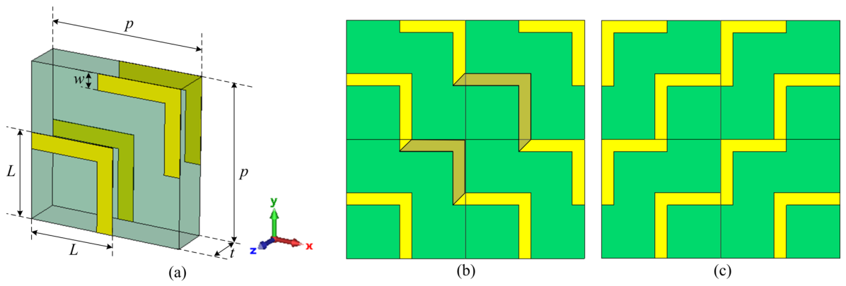
Figure 1a shows a schematic diagram of the unit cell that consists of a pair of L-shaped resonators printed on both sides of a printed circuit board (PCB). Each resonator is formed by two perpendicular metallic strips of equal length
L and width
w, arranged at 90°. The position of the L-shaped resonators is designed to promote electrical continuity between adjacent unit cells. As a result, the whole structure forms a two-dimensional periodic array of staircase-shaped conductive traces with constant width
w, printed on both sides of the PCB.
Figure 1b shows a
array of unit cells in the configuration for linear-to-RHCP conversion. The resulting staircase is formed by two consecutive steps of slightly different electrical lengths, which alternate along the structure. This deliberate “short/long” alternation is expected to introduce two closely spaced resonances instead of a single isolated one. Furthermore, due to the 90° rotational symmetry of the structure, a mechanical rotation of the sample by 90° enables handedness switching in transmission (see
Figure 1c). This property was previously exploited in transmissive LTC implementations [
10].
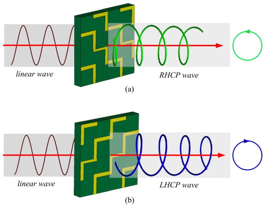
Figure 2 shows schematic diagrams of the sample configurations for linear-to-RHCP (a) and linear-to-LHCP (b) conversion.
Unlike metasurfaces based on discrete resonant inclusions, the metallic pattern forms electrically continuous conductive paths across adjacent unit cells. As a result, the induced surface currents are not confined to localized elements but can propagate along extended trajectories, leading to smoother spectral variations [
18]. Similar broadband behaviors have been reported in polarization converters based on meandered elements [
19,
20,
22].
2.2. Linear-to-Circular Polarization Description
We consider that an incident, linearly polarized plane wave,
, impinges normally on the metasurface. Due to the anisotropic response of the structure, the transmitted field contains both a co-polarized component,
, and a cross-polarized component,
. The transmitted field can therefore be written as
where
and
denote the complex transmission coefficients from the incident
polarization into the transmitted
and
components, respectively.
Circular polarization in transmission is achieved when these transmission components have comparable amplitudes and a phase difference close to
:
The polarization state is characterized using the axial ratio (AR), defined as [
3]
where
Based on this definition, one of the main objectives of this work is to maximize the axial ratio bandwidth (ARBW), defined as the ratio between the frequency range over which and the central frequency of this band .
The energy balance of the metasurface can be described in terms of the transmittance
T, reflectance
R, absorption
A, and insertion loss
, which are defined as follows:
This formulation allows us to distinguish between losses due to impedance mismatch (reflection) and intrinsic losses within the structure (absorption).
The polarization handedness of the transmitted wave can be described using the ellipticity
with
corresponding to pure RHCP (+) or LHCP (−).
As a complementary way to describe the LTC polarization conversion, the power fractions carried by the right- and left-handed circular components can be used:
3. Performance Optimization
A parametric analysis is first conducted in order to provide a global overview of the dependence of the central operating frequency, , and the ARBW on the geometrical parameters of the metasurface. The objective is to identify the regions of the design space that maximize the LTC polarization conversion at the microwave X band (8–12 GHz).
The analysis is performed by simulating 100 distinct configurations of the geometrical parameters
L and
w, while keeping the thickness of the dielectric substrate at
mm constant. For this purpose, a Latin Hypercube Sampling (LHS) strategy was employed, which ensures a quasi-uniform coverage of the multidimensional domain with a limited number of samples [
23,
24]. The segment length is varied within
mm, and the width within
mm.
Simulations were carried out using CST Studio Suite 2025® with a frequency-domain solver. A single unit cell was modeled with periodic boundary conditions along the x- and y-directions to emulate an infinite metasurface and open (“add space”) boundaries along z. The structure was excited by a normally incident plane wave with linear polarization along the y-axis using waveguide ports. A tetrahedral mesh with adaptive refinement was employed, with a minimum mesh size of approximately 0.08 mm near the metallic elements. Convergence was ensured by limiting variations in the S-parameters to below 0.02 dB between successive refinements.
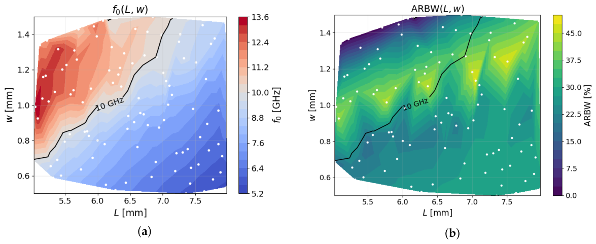
Figure 3a shows the variation of the central frequency
as a function of
L and
w. It can be observed that
exhibits a clear dependence on the resonator length
L, with larger values of
L shifting the response toward lower frequencies, in agreement with the expected scaling of electrically longer current paths. In contrast, the width
w has a secondary influence, introducing smoother variations. The contour corresponding to
GHz, i.e., the center of the X band, is also indicated.
The ARBW map,
Figure 3b, reveals the presence of a ridge spanning the design space with a positive slope. The highest ARBW values are obtained for larger values of
L combined with intermediate-to-large values of
w, indicating that extended current paths promote broadband polarization conversion. The contour corresponding to
GHz highlights a reduced region of the design space where broadband performance and X-band operation coexist.
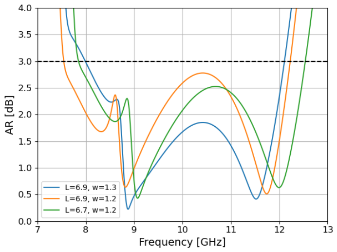
Based on this analysis, three representative configurations that provide LTC operation across the entire X band are shown in
Figure 4. However, selecting the optimal design based solely on ARBW may be misleading, as it does not account for robustness or spectral stability.
To address this limitation, additional performance metrics are introduced to evaluate both the average behavior and the sensitivity of the AR within the operating band. In particular, statistical indicators such as the mean axial ratio (), its standard deviation (), and the 95th-percentile value () are used to rank the candidate designs and select the final prototype.
In addition, a flatness metric is considered, defined as the mean absolute gradient of the AR within the selected operating band:
where
denotes the frequency samples within the selected band, and
N is the number of points in that interval. Low flatness values correspond to smoother AR responses, i.e., reduced in-band variations and ripple.
These metrics are used as practical indicators of robustness against fabrication tolerances, since they capture not only the average performance but also the dispersion and the margin with respect to the specification limits [
25]. In this way, bandwidth and robustness-related aspects can be evaluated together within a consistent design framework [
26].
Table 1 summarizes the geometrical parameters and the main performance metrics of the three selected configurations. Design 2 achieves the largest ARBW (47.3%). However, it also exhibits the highest values of flatness (2.26) and
(2.77 dB), together with the largest average axial ratio (
dB). This indicates a less uniform spectral response and a smaller statistical margin with respect to the 3 dB threshold, suggesting increased sensitivity to small geometrical deviations.
By contrast, Design 1 provides the lowest average axial ratio (1.49 dB), the lowest flatness (2.07), and a comparatively low (2.67 dB), which points to a smoother and more stable in-band response. Although its ARBW is the smallest among the three candidates (40.8%), it remains sufficient to cover the target X-band operation. For this reason, Design 1 was selected as the most conservative option, prioritizing robustness against fabrication tolerances over the absolute maximum bandwidth.
This choice is particularly motivated by the presence of a local AR maximum between the two in-band minima,
Figure 4, since a smoother response is expected to keep that intermediate peak farther from the 3 dB limit under possible fabrication-induced shifts.
4. Simulation
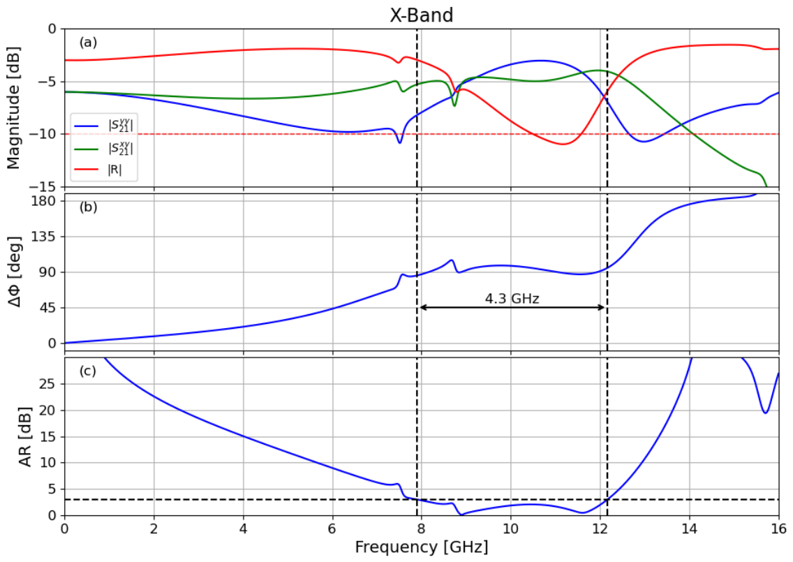
Figure 5 summarizes the main electromagnetic indicators used to evaluate the polarization-conversion performance of the selected configuration (Design 1), which was identified as the reference solution after the optimization stage.
The magnitude of the cross-polarized transmission coefficient,
, is observed to be comparable to that of the co-polarized component,
, within the frequency range delimited by the vertical dashed lines. This amplitude balance, together with a phase difference close to 90°, fulfills the well-known conditions required for linear-to-RHCP conversion [
3]. As a result, the axial ratio remains below 3 dB over a bandwidth of approximately 4.3 GHz, with a mean value of 1.49 dB,
Table 1, confirming efficient circular polarization generation across the operating band.
Figure 5 also shows the reflectance (
R). The corresponding impedance-matching bandwidth, defined as the frequency range where
(equivalent to
dB reflected power), extends from 10.4 to 11.6 GHz. This bandwidth is significantly narrower than the ARBW defined by the conventional LTC criterion
. This result indicates that polarization conversion is maintained over a wider frequency range than that satisfying the conventional
dB matching condition.
It is worth noting the presence of two pronounced minima in the AR response, located at about ≈8.9 GHz and ≈11.6 GHz. These minima are directly associated with the frequencies at which and intersect while the phase difference approaches 90°, leading to an optimal balance between orthogonal field components and, therefore, near-ideal circular polarization.
From a physical standpoint, a phase difference close to 90° indicates that the transmitted orthogonal components are in quadrature, resulting in circular polarization. In contrast, at the lower edge of the simulation band, , approaches 0 while , which can be interpreted as the wavelength being larger than the step sizes, and the structure behaves like a parallel grid oriented at 45°. Furthermore, at high frequencies, for GHz, , and the transmitted wave is linearly polarized.
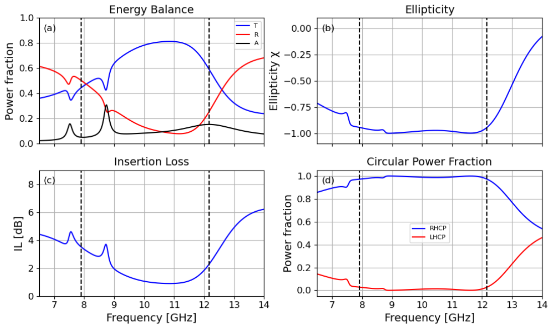
Figure 6 summarizes both the energy balance (left column) and the polarization-conversion performance in the circular basis (right column) of the selected configuration (Design 1).
The left column shows the main energetic indicators. Within the LTC conversion band delimited by the vertical dashed lines, the metasurface exhibits transmittance ranging from 0.42 to 0.8, with a mean value of 0.7, while reflectance remains moderate and absorption is relatively low. This indicates that a significant portion of the incident power is transmitted through the structure, which is sufficient to ensure the amplitude balance required for LTC conversion and is consistent with the insertion loss (IL) remaining below 3.8 dB across the operating band.
It is worth noting that reflection is not minimized as a primary design objective, since the device is intended for transmissive polarization conversion rather than radiation.
The right column characterizes the polarization state of the transmitted field. The ellipticity remains close to within the operating band, indicating that the transmitted wave is predominantly right-hand circularly polarized (RHCP). This is further supported by the circular power fractions: the RHCP component dominates across the band, with approaching unity within the conversion band, while the LHCP contribution remains significantly lower.
These results confirm that the metasurface not only ensures adequate transmission with moderate losses but also effectively converts the incident linear polarization into a well-defined circular polarization state with high purity.
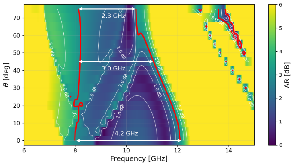
Figure 7 presents the AR as a function of frequency and incidence angle, providing a comprehensive view of the angular stability of the proposed metasurface. The colormap represents the AR in dB, while the contour corresponding to AR = 3 dB (highlighted in red) defines the LTC operating region.
It can be observed that the metasurface maintains a relatively stable lower frequency limit, which remains close to 8 GHz across the entire angular range. In contrast, the upper frequency limit exhibits a noticeable shift toward lower frequencies as the incidence angle increases. Specifically, the upper bound decreases from approximately 12.1 GHz at normal incidence to 11.1 GHz at 45° and further down to about 10.4 GHz at 75°.
As a consequence, the ARBW gradually decreases with increasing incidence angle. Nevertheless, the metasurface preserves a significant operating bandwidth, with ARBW at 45° and still at 75°. These results demonstrate a reasonably robust angular performance, particularly considering the transmissive nature of the structure.
From a physical perspective, this behavior can be attributed to the increased phase mismatch between the orthogonal transmitted components under oblique incidence, which primarily affects the higher-frequency edge of the band. Despite this effect, the structure maintains the amplitude and phase balance required for LTC conversion over a wide angular range.
This asymmetrical bandwidth degradation suggests that the LTC mechanism is more sensitive to angular dispersion at higher frequencies, where the effective electrical length and inter-element coupling are more strongly perturbed.
5. Experimental Validation
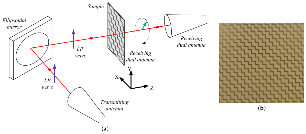
In order to characterize the sample, we used a free-space technique adapted to characterize chiral media [
27]. The incident beam was focused by an ellipsoidal concave mirror so that diffraction problems were negligible with relatively small samples of 14 cm diameter [
28]. The transmitting antenna was placed at one of the mirror foci and the sample at the other one. A dual-polarized antenna, Flann DP240 (Flann Microwave Ltd, Bodmin, Cornwall, United Kingdom) was used to measure the scattering parameters
and
. A time-domain transformation was used to filter out mismatches from the antennas, edge diffraction effects, and unwanted reflections.
Figure 8 shows a schematic diagram of the free-wave experimental system and a picture of the sample.
The experimental metasurface was built by patterning an array of
unit cells on both sides of a standard FR4 board (
,
, and a copper metallization thickness of 35
m). The total size of 19.5 cm × 19.5 cm was found to be sufficiently large to minimize edge diffraction effects [
28].
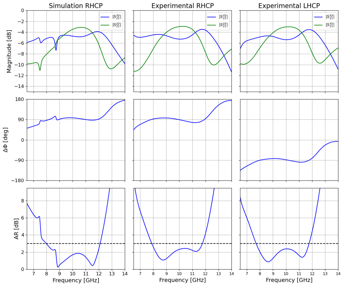
Figure 9 compares the simulated and measured responses of the optimized two-layer metasurface (Design 1) for both RHCP and LHCP configurations. From top to bottom, the figure shows the magnitudes of the co- and cross-polarized transmission coefficients, the phase difference, and the resulting AR.
Overall, the experimental results reproduce the main features predicted by full-wave simulations, demonstrating good agreement in both amplitude and phase responses across the operating band. A single wideband LTC region is observed, where the measured AR remains below 3 dB, confirming effective polarization conversion.
A slight frequency shift between simulations and measurements is observed, with the experimental band appearing displaced with respect to the simulated one. This shift is attributed to fabrication tolerances, including deviations in conductor dimensions, uncertainties in substrate permittivity, and minor misalignment in the free-space measurement setup.
It is worth noting that the simulated response exhibits additional narrow resonant features below 8 GHz, as well as a localized perturbation around the first AR minimum, where and intersect. These features manifest as small ripples in both the phase difference and the axial ratio curves. However, such fine resonant effects are not observed in the experimental results. This discrepancy can be attributed to the idealized conditions assumed in full-wave simulations, which capture high-Q resonant phenomena that are typically smoothed out in practice due to fabrication tolerances, material losses, and the limited resolution of the measurement setup. Importantly, these minor discrepancies do not affect the identification of the LTC operating band.
Finally, the phase difference plots clearly confirm the expected polarity inversion when the sample is rotated by 90°. The sign of reverses consistently across the band, demonstrating robust mechanical switching between left- and right-handed circular polarization states. Despite the observed frequency offsets, the measured axial ratio remains below 3 dB over a broad bandwidth, confirming that the proposed metasurface maintains its performance under practical experimental conditions.
6. Discussion
To provide a qualitative physical picture,
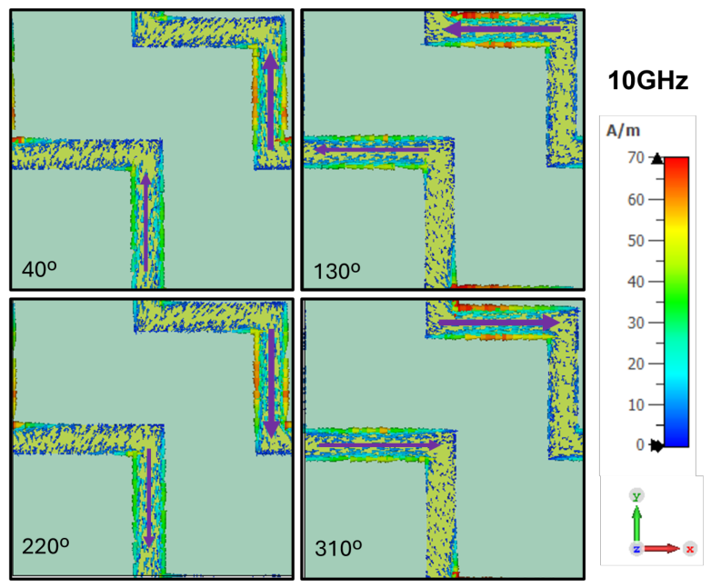
Figure 10 shows the surface current distributions obtained using CST Studio Suite (Frequency Solver) under normal incidence and linear vertical (
y-direction) excitation. Four phase instants separated by 90°, spanning a full oscillation cycle, are presented for a representative frequency within the LTC band. The behavior is similar across the entire conversion band. For clarity, only the currents in the second layer (i.e., the staircase responsible for the transmitted signal) are shown, and the current direction is explicitly indicated by arrows.
It is noteworthy that a vertically polarized incident electric field induces strong surface currents in the horizontal (
x-aligned) segments of the staircase. This indicates that the structure supports a resonant response in that direction, which can be attributed to near-field coupling within the staircase geometry and between layers. This behavior is consistent with the coupled response typically observed in L-shaped resonators [
10,
29].
It can be observed that the main currents flowing along the two steps are in parallel, indicating that they are resonating in a similar way, although the current intensity is lower along the lower-left step. Initially (), the current is predominantly directed upwards; a quarter period later, it points to the left (); then downwards (); and finally to the right (). This indicates that the horizontal and vertical sections of the staircase resonate in quadrature. Overall, the current circulates along the staircase in a counterclockwise direction.
This temporal evolution reveals that the surface current vector undergoes a continuous rotation, which is the signature of two orthogonal current components with comparable amplitudes and a phase shift close to 90°.
For all frequencies within the LTC band, the superposition of these orthogonal current components, with similar amplitudes and near-quadrature phase, leads to the radiation of a transmitted field whose orthogonal components satisfy the conditions required for circular polarization. Therefore, the linear-to-circular polarization conversion can be interpreted as a direct consequence of the rotating surface-current distribution supported by the staircase geometry.
Table 2 summarizes and benchmarks representative LTC polarization converters reported in the literature. It can be observed that different design approaches coexist. On the one hand, structures based on extended current paths, such as meander-line configurations [
20,
22], tend to provide wideband performance, due to their distributed electromagnetic response. On the other hand, resonator-based designs, including patch-type, ring, or Jerusalem-cross elements [
7,
8,
19], typically offer additional functionalities such as reconfigurability or enhanced angular stability, although often at the expense of reduced bandwidth. In this context, our previous work [
10], based on L-shaped resonators, achieved an ARBW of 26% with low insertion loss but remained limited by its resonant nature. In contrast, the present design introduces electrical continuity between adjacent unit cells, enabling a distributed-current response that increases the ARBW (up to 41%), reduces the electrical thickness (from 0.19
to 0.10
), and improves angular stability, at the expense of higher insertion loss (IL between 0.9 and 3.8 dB compared to 0.2–1.2 dB). Furthermore, low-profile implementations are generally associated with planar single-layer or compact resonant geometries [
8,
20], whereas multilayer or volumetric approaches may improve performance metrics at the cost of increased thickness [
22,
30].
Overall, the proposed design combines a low-profile implementation with wideband response and angular stability while preserving reconfigurability through mechanical rotation [
10], thus providing a favorable trade-off between bandwidth, structural simplicity, and reconfigurability. Notably, it achieves full X-band coverage with a compact two-layer structure and moderate insertion loss, while maintaining a low-profile structure and enabling passive reconfigurability.
The proposed staircase metasurface is inherently scalable to other frequency bands through straightforward geometric scaling. As an illustrative example, a similar optimization procedure was conducted with the objective of covering the entire Ku-band.
In this case, a reduced substrate thickness of mm was selected to facilitate operation at higher frequencies. The optimized geometrical parameters were found to be mm and mm, leading to a full coverage of the Ku-band. As expected, the overall dimensions of the structure are smaller than those obtained for the X-band design, in accordance with the scaling of the effective electrical length.
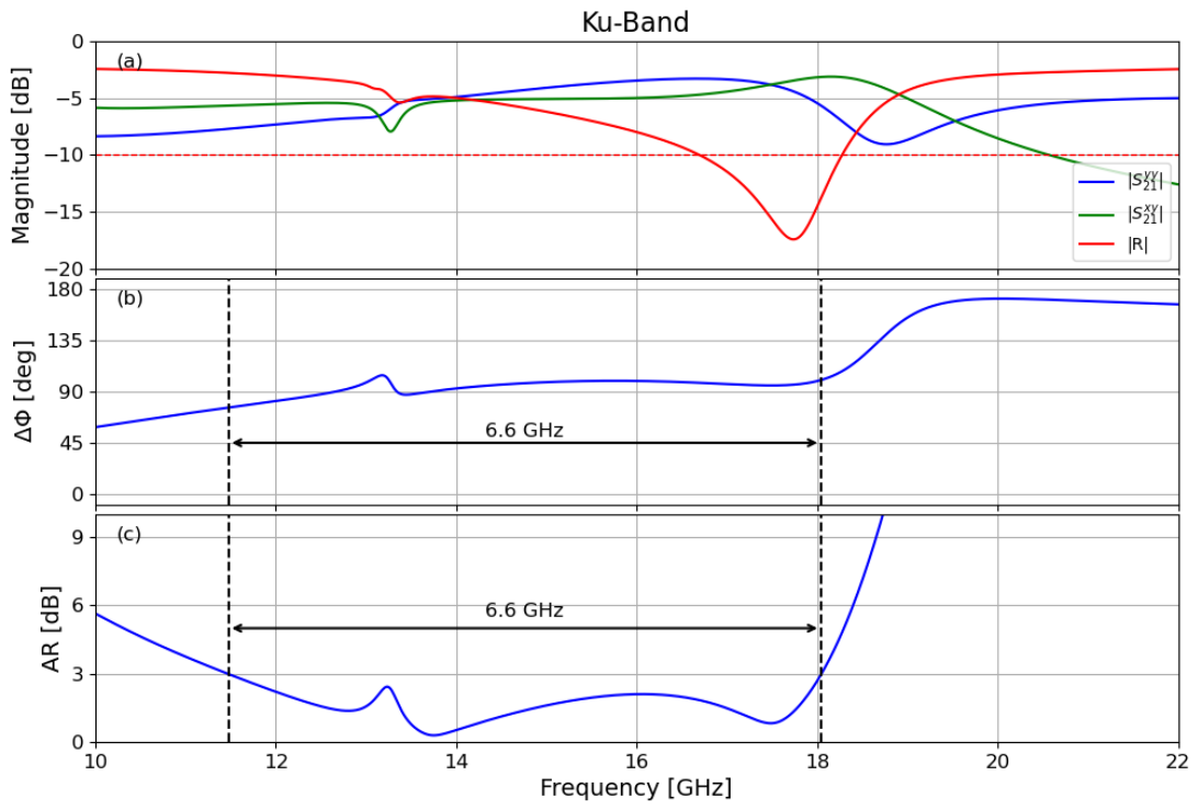
Figure 11 shows the transmission coefficients in the 10–22 GHz range, together with the phase difference between
and
, and the resulting AR. The obtained bandwidth is 6.6 GHz, centered at
GHz, which corresponds to an ARBW of 44.9%.
Similar to the X-band case, the AR exhibits two pronounced minima (approximately 13 GHz and 17.5 GHz), separated by a local maximum. This behavior is consistent with the presence of two closely spaced resonant modes associated with the staircase geometry, confirming that the underlying LTC conversion mechanism is preserved under scaling.
These results demonstrate that the proposed design strategy can be readily extended to higher frequency bands without altering the fundamental operating principles, making it a versatile candidate for broadband polarization control across the microwave spectrum.
7. Conclusions
In this work, a staircase-shaped transmissive metasurface for linear-to-circular (LTC) polarization conversion is presented as an evolution of a previous design based on discrete L-shaped resonators [
10]. In the proposed structure, the individual L elements are electrically connected, which introduces continuity between adjacent unit cells and allows currents to flow along extended paths instead of being confined to localized resonances.
As a consequence, the electromagnetic response becomes more distributed, and the operational bandwidth increases significantly. In particular, the ARBW improves by approximately 41%, covering the entire X band (8–12 GHz). This improvement is mainly related to the reduction of dispersion and the smoother spectral behavior of the structure.
The metasurface was experimentally validated, showing good agreement with full-wave simulations. In addition, the structure preserves the capability to switch between right- and left-handed circular polarization (RHCP/LHCP) by means of a simple 90° mechanical rotation, without requiring active components or biasing networks.
The proposed design also shows improved performance under oblique incidence. The LTC response remains relatively stable as the incidence angle increases, maintaining an ARBW above 33% for angles up to 45°.
Finally, the structure is scalable to other frequency bands, since the operation mainly depends on geometrical parameters. This is demonstrated by means of a Ku-band (12–18 GHz) design, which presents similar broadband behavior.
Overall, the results indicate that metasurfaces based on electrically continuous and distributed-current structures can overcome some of the bandwidth limitations of conventional resonant designs while maintaining a simple geometry and robust performance.




 ,
,