1. Introduction
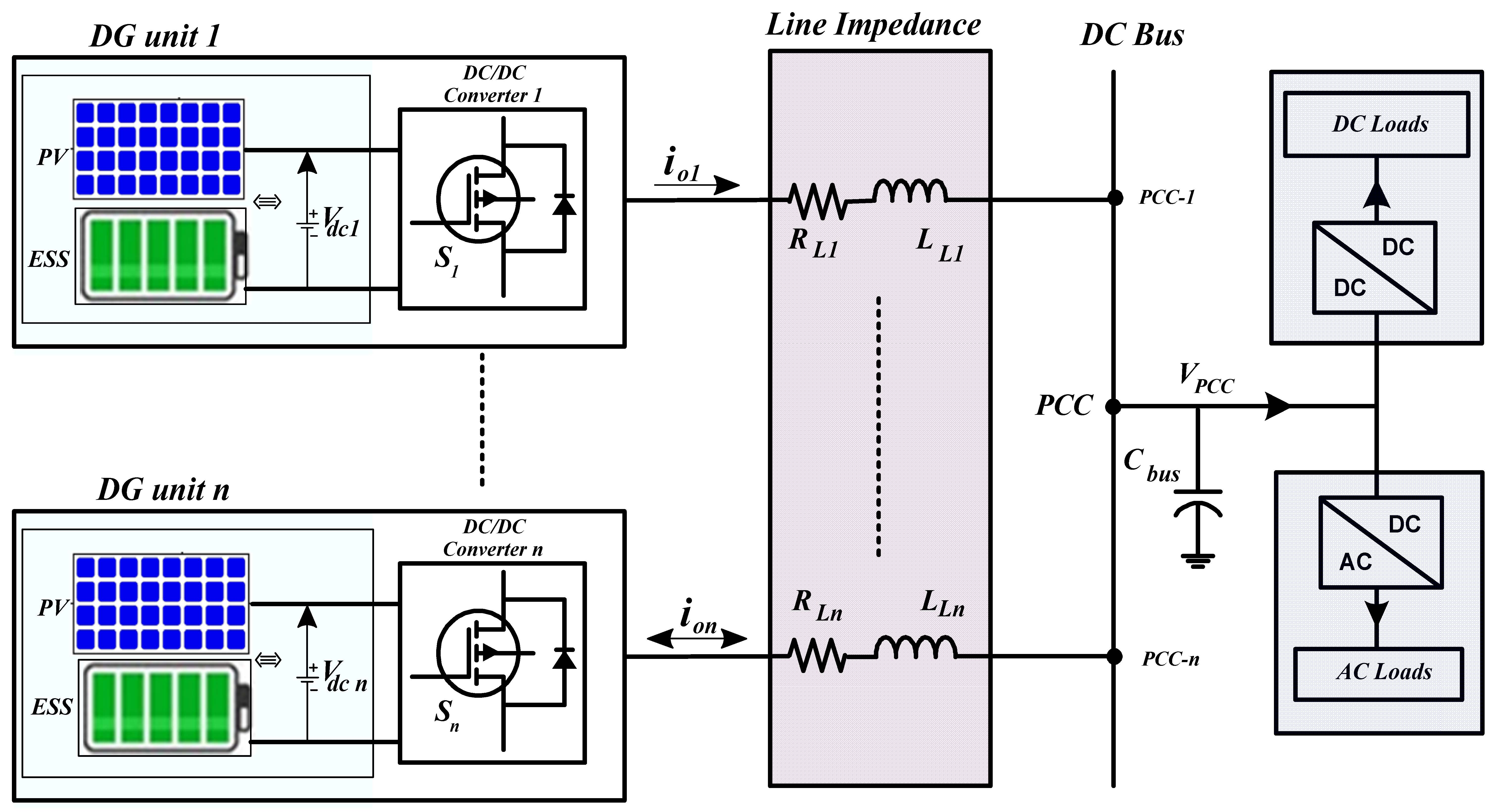
A microgrid is a localized power grid system that is capable of operating in either grid-connected or autonomous mode by leveraging various distributed generation (DG) units and energy storage systems (ESSs) to supply local loads. Microgrids can be primarily categorized into three types based on their system architecture and voltage characteristics: (1) AC microgrid, (2) DC microgrid, and (3) Hybrid AC/DC microgrid. DC microgrids offer several key advantages compared to AC microgrids [
1].
These advantages include higher efficiency, reduced control complexity, and fewer power electronic converters. Additionally, DC microgrids offer improved power quality by eliminating harmonics typically associated with AC systems, simplified frequency control, reactive power compensation, and easier energy storage management [
2,
3,
4]. Even though parallel-connected distributed generation units in DC microgrids offer numerous benefits to meet load power supply reliability, they also introduce several challenges related essentially to voltage regulation, load power sharing among DG units, and system stability [
4]. The general configuration of an islanded DC microgrid along with its main components is shown in
Figure 1.
Distributed generation units are defined as small, modular power-generating units installed in close proximity to end users. These DG systems are primarily based on the integration of locally available energy resources, such as solar, wind, and hydropower, which is particularly relevant in the context of Ethiopia and other African countries. Moreover, DG systems can operate at various power levels, typically ranging from several kilowatts to larger systems capable of generating up to several megawatts [
5].
In the context of DC microgrid operation, various control strategies have been employed to address load power sharing and maintain voltage stability, as these are crucial aspects for ensuring the system stability and reliability. These control strategies can be classified intro centralized, distributed and decentralized control strategies, depending on their communication dependency [
6]. Centralized controllers have shown proven performance in achieving the desired load sharing and voltage regulation. However, they require high-speed communication links that make the whole system stability vulnerable to single-point failure. Distributed control strategies have been also developed in the literature showcasing satisfactory performances for primary control, as well as for secondary control [
7]. These techniques still face challenges related to communication time delay and failures. Research papers [
8,
9] have proposed decentralized controllers for DC microgrids as an approach to achieve load power sharing without the need for communication facilities [
10].
Among these control strategies, the conventional V/I droop control method achieves satisfactory results in terms of power sharing, but at the expense of increased voltage deviations and limited dynamics in the presence of load variations [
11]. A P/V two-layer droop power sharing control [
12], a robust droop based sliding mode control [
13], and an intelligent droop power sharing based on fuzzy logic sliding mode control [
14], as the proposed scheme in paper [
15], presents an adaptive droop control that improves load power sharing and voltage stability in DC microgrids, as compared to conventional fixed droop control. Similarly, a distributed hierarchical control method incorporating both droop-based primary control and secondary control has been proposed in [
16] in order to achieve load power sharing as well as maintain voltage stability in DC microgrids. In [
17], the authors propose a distributed secondary control scheme to maintain voltage stability in DC microgrids without compromising load current sharing performances.
Master–slave control and droop-based control are two common primary-level strategies employed to ensure stable operation in parallel-connected DG units. Master–slave control requires fast communication and is vulnerable to single-point failures, as it relies on the master unit [
18,
19]. In contrast, the droop control mechanism is more reliable for DC microgrids since it does not depend on external communication. This enables plug-and-play capabilities, which facilitate power sharing and voltage stability without the need for centralized coordination [
20,
21,
22].
In paper [
23], a control scheme based on a disturbance observer has been proposed to achieve accurate voltage control and load sharing in a DC islanded microgrid. A new nonlinear decentralized back-stepping control strategy is used to achieve voltage control and load sharing. The control system is robust against the load variations and microgrid parameters’ uncertainties. In [
24], a Luenberger observer is used with a modified adaptive sliding mode controller to estimate the unknown input voltage and load resistance in photovoltaic system. Reference [
25], proposes the use of a state observer based parameters estimation in DC-DC converter modeling. Additionally, it compares performances of Luenberger state observer and extended Kalman filter have been compared considering convergence precision and rapidity. In [
26], an extended state observer-based droop control approach is used to estimate the unknown load disturbance in DC–DC buck converters, in which a composite controller is employed to eliminate effects of the disturbance based on its estimates. In [
27], a disturbance observer-based finite time controller is proposed to estimate the unknown load variations and model uncertainties of a DC–DC converter feeding constant power loads (CPLs).
Reference [
28] proposes a Luenberger observer-based control strategy to improve power quality in microgrids with nonlinear loads, by accurately identifying voltage and current components at various frequencies. The strategy, which eliminates the need for communication lines, enhances power-sharing conditions, and reduces harmonic and negative sequence voltages.
The presence of uneven line impedances and load variations can result in unregulated output voltages, leading to an imbalance in power sharing among parallel-connected DG units. To address these limitations, a Luenberger observer-based power sharing control method is proposed in this study in order to achieve load sharing while maintaining reduced voltage deviations in DC islanded microgrids.
This study’s main contribution is the development of a Luenberger observer-based control method to achieve equal power sharing among parallel DG units in an islanded DC microgrid. The Luenberger observer is used to estimate the PCC voltage based on available output voltage and current measurements from each DG unit. This method exploits only locally available measurements without the need for communication. The estimation of the PCC voltage is exploited to achieve equal current sharing between interconnected DG units, even in the case of unmatched line impedance, while maintaining voltage deviations in acceptable ranges. Unlike conventional droop control, which compromises voltage regulation, this approach ensures both precise load sharing and voltage regulation. The Luenberger observer replaces physical voltage sensors by estimating PCC voltage, enhancing control reliability and system simplicity.
This paper is organized as follows:
Section 2 describes the model of islanded DC microgrids, including the model of DC–DC converters and line impedance.
Section 3 presents the conventional droop control method.
Section 4 deals with the proposed Luenberger observer-based power sharing control method. The simulation results are then verified in
Section 5 to validate the performance of the proposed observer-based technique. Additional tests are conducted using real-time simulation on the OPAL-RT OP4512 target. Finally,
Section 6 presents the conclusions of the study.
2. Modeling of Islanded DC Microgrid
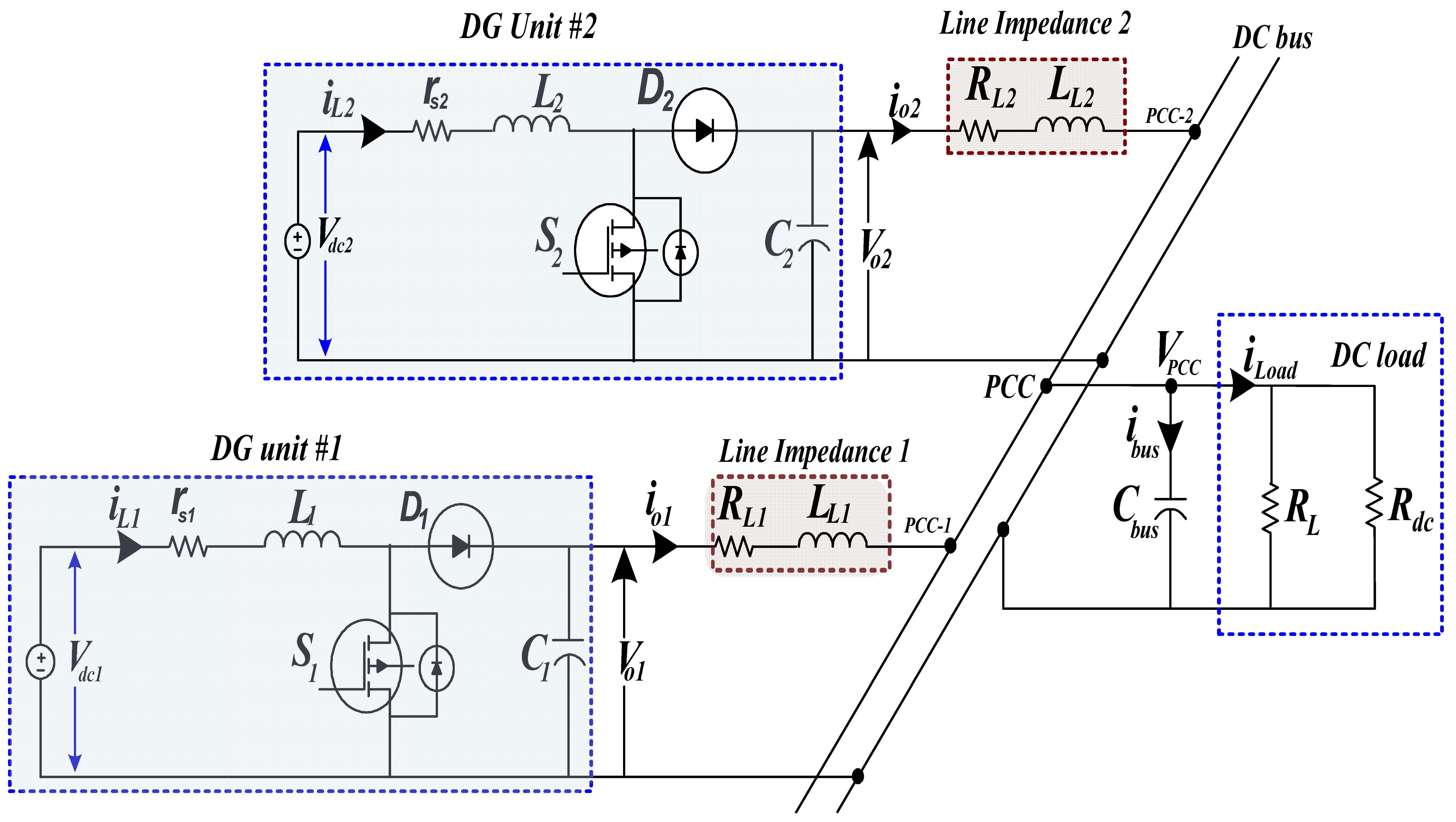
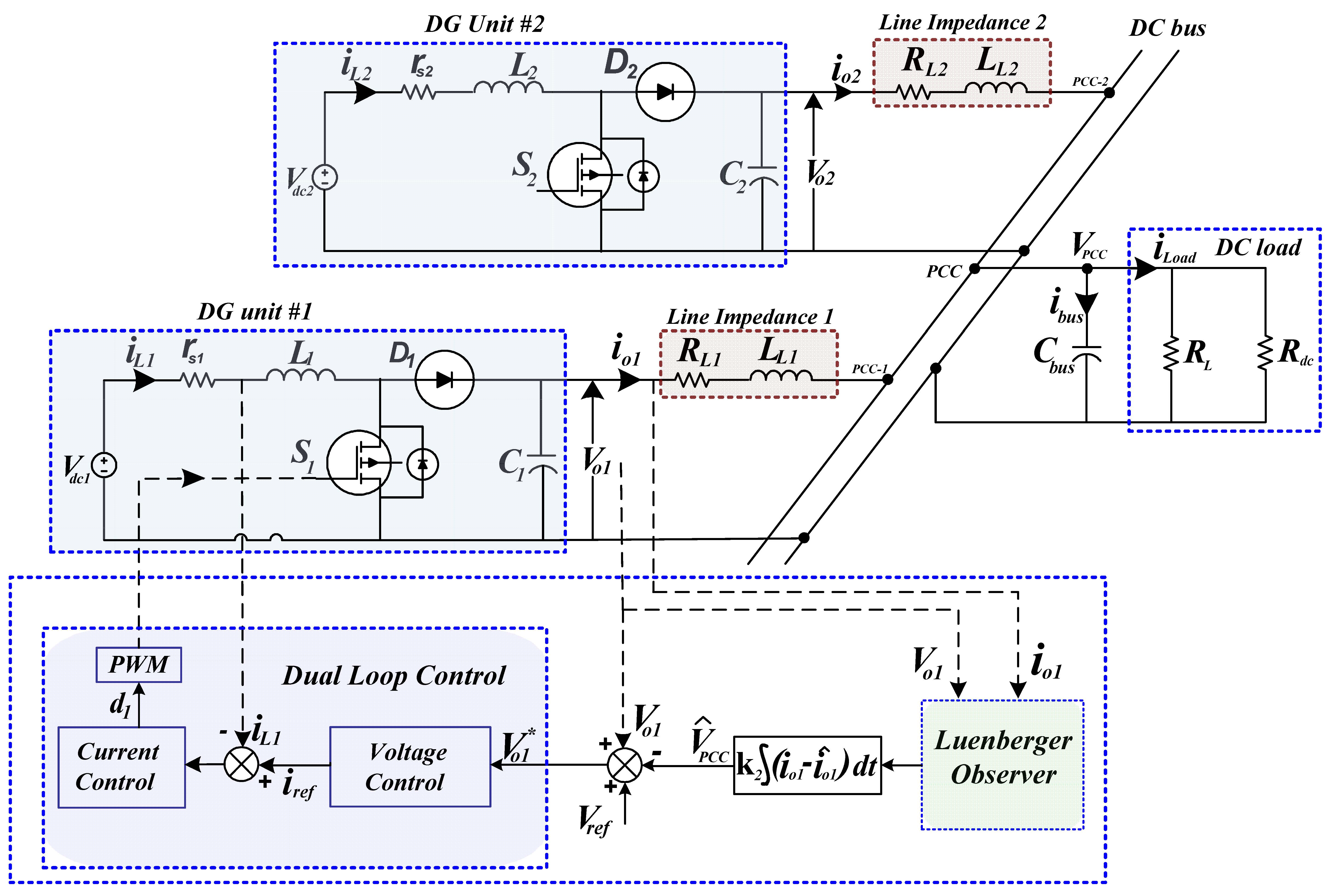
The islanded DC microgrid model studied, as shown in
Figure 2, consists of parallel-connected distributed generation units with a boost converter and unmatched line impedances. The DC microgrid has two parallel-connected DG units, comprising a DC voltage source, boost converter, and the LC filter which is connected to the common DC bus at the PCC via unmatched line impedances (Z
Li). These line impedances play a causal role by inducing voltage drops that directly determine the PCC output voltage (V
PPC) and the corresponding line currents (i
oi) delivered to the common loads. The DC voltage source in each DG unit represents either a distributed energy resource (DER) or a battery energy storage (BES) system. However, the photovoltaic (PV) system and the BES system are not discussed in this paper.
2.1. DC-DC Boost Converter Dynamics
In a DC microgrid, power converters are designed with varying configurations to meet specific application and operational requirements [
2,
29]. Among these, the boost converter is a fundamental topology for DC–DC power conversion. A boost converter is implemented to generate the desired voltage level, which is then used to supply a local DC load connected to the PCC through a line impedance as illustrated in
Figure 2.
The averaged dynamic behavior of the inductor current and capacitor voltage in the ith boost DC–DC converter, is described by the following equations [
25]:
where the output variables are
iLi, inductor current in each boost converter, and
Voi, the output voltage of the ith DG unit. The input variables are
Vdci as the input DC voltage supplied to the boost converters, and
ioi as the line current between the ith DG and the common bus. The parameters are
Li, the inductance of the converter,
rsi, the internal series resistance of the inductor;
Ci, the output capacitance of the converter, and
di, the duty cycle controlling the switch
Si in the ith converter. The subscript
i represents the specific of DG units in the islanded DC microgrid,
i = 1, 2.
2.2. Line Impedance Dynamics
In the DC microgrid, the line impedance between each DG unit and the common DC bus is modeled by the line resistance
RLi and inductance
LLi. Applying Kirchhoff’s voltage law (KVL) to the circuit in
Figure 2, the differential equation describing the line current,
ioi can be expressed as follows:
where the output variable,
ioi, is the line current between the ith DG and the common bus. The input variables are
Voi, the output voltage of the ith DG unit, and
VPCC, the voltage at the PCC on the DC bus. The parameters are
RLi and
LLi, the line resistance and inductance between the ith DG and the common bus, respectively,
2.3. DC Bus Voltage Equation
The DC bus voltage at the PCC can be modeled by considering the behavior of the DC link capacitor, C
bus, and applying Kirchhoff’s current law (KCL) to the electrical scheme of
Figure 2 as follows:
The total load current,
iLoad, is given as the sum of the individual line currents,
ioi:
where the output variables,
VPCC, are the voltage at the PCC on the DC bus. The input variables are as follows;
ioi is the line current between the ith DG and the common bus, and
iLoad is the total load current drawn by the DC load connected to the common DC bus. The parameter,
Cbus, is the capacitance of the DC bus;
i ranges from 1 to
n, where
n represents the total number of DG units in the DC microgrid system. In this study,
n = 2.
The bus current
ibus through the DC link capacitor as shown in
Figure 2 are very insignificant, since for the DC system, the frequency is zero
f = 0, so capacitive reactance (X
C) goes to infinity. So, ideally, at steady-state condition the bus capacitor behaves like an open circuit and no current through the bus capacitor is zero.
The main function of the DC link capacitor, Cbus, is to smooth out voltage fluctuations and filter high-frequency noise/ripples caused by switching operations in power electronics. In this work, the interlinking impedance between the parallel-connected DG units is neglected, and both units share a common capacitive link at the PCC.
The dynamic differentials (2) and (3), which describe the interconnection model of DG units with the common DC bus, enable the derivation of the state–space representation for the islanded DC microgrid model with two parallel-connected DG units [
30], and can be expressed as follows:
For equal current sharing between the two DG units, the differential expression in (6) becomes zero after substituting (4) into (6). In practice, the load current () is nearly equal to the sum of the individual line currents, , supplied by each DG unit, since losses in the connecting lines are minimal. Moreover, the voltage at the PCC, , is observed to change very slowly compared to the dynamic variations of the line currents. This slow change is typically attributed to the relatively large capacitance at the DC bus, , which serves to buffer voltage fluctuations. Therefore, for the purpose of observer design, we assume that , effectively treating the PCC voltage as a constant over the time scale.
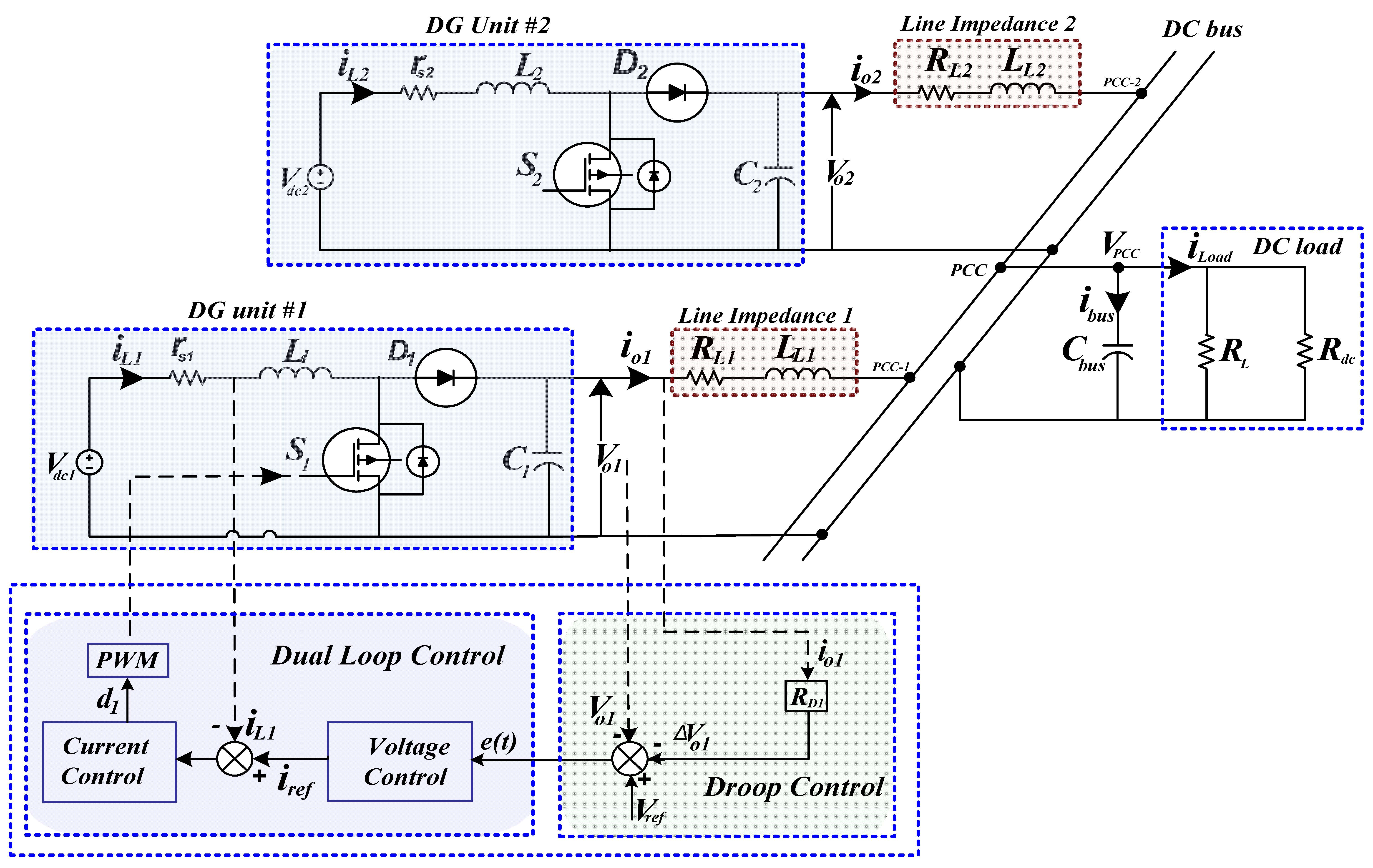
3. Conventional Droop Control Method
The primary control layer of a DC microgrid consists of inner control loops and droop control. Droop control is a widely used technique for achieving power sharing among parallel-connected DG units in a DC microgrid [
11]. As shown in
Figure 3, droop control provides the voltage reference to the inner control loops, enabling the parallel operation of DG units.
In the traditional droop control technique, the voltage reference is dynamically adjusted based on the output current to achieve load sharing among the parallel DG units and is described by
where
Voi is the output voltage of ith DG unit;
Vref is the reference voltage under no load condition;
ioi is output current from ith DG unit; and
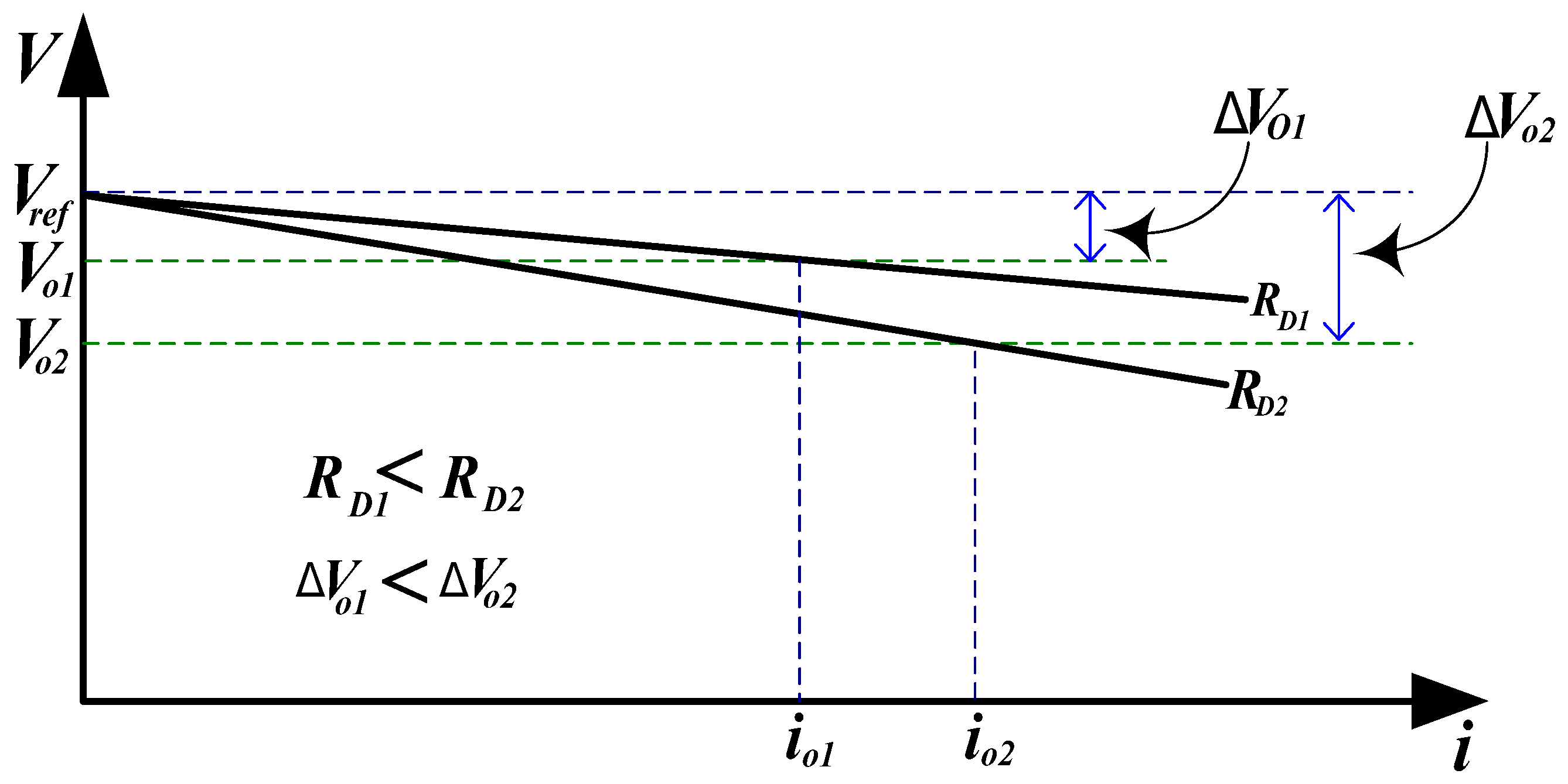
RDi represents droop coefficients. The droop control mechanism facilitates proportional load sharing among parallel DG units by allowing the output voltage to decrease (droop) as the output current increases as illustrated in
Figure 4.
The conventional droop controller for a DC–DC boost converter employs a double-loop PI control system. The outer voltage loop regulates voltage by comparing the output with the reference and generating a reference current for the inner loop [
11].
The voltage controller receives the voltage error signal, e(t), which is defined as the difference between the new reference voltage and the actual measured output voltage, as follows:
At steady state, the PI controller ensures that the voltage error signal is driven to zero. Therefore, when the output voltage exactly tracks the reference voltage, the error becomes zero. The voltage controller processes this error to generate the reference current () for the inner current loop.
The inner loop then compares this reference with the inductor current and generates a control signal, which is processed by the PWM block to produce the switching signal, as shown in
Figure 3.
There is a tradeoff between accurate load power sharing and bus voltage regulation, making it challenging to achieve equal load current sharing while maintaining the DC bus voltage at the reference value [
31,
32]. These two limitations of the conventional droop control method are discussed in detail below: one is the voltage deviation caused by the droop slope and line resistance, and the other is the decrease of power sharing accuracy.
3.1. DC Voltage Deviation
As illustrated in
Figure 4, the conventional droop current sharing control is based on adjusting the voltage reference of each DG unit according to the desired output power.
These control methods result in a voltage slope that presents important voltage deviations (ΔVoi) from the reference voltage (Vref). These deviations depend on the droop gain setting, as well as on the operating point.
These voltage deviations can be expressed as follows:
To restrict the voltage deviation within the permissible range, the value of the droop coefficient
RDi must be limited:
where Δ
Voi, max is the maximum allowable voltage deviation of the rated DC bus voltage and
ioi, max is the full load current of any converter. To ensure stable operation of the DC microgrid, the DC bus voltage must be maintained within the permissible range, typically ±5% of the nominal voltage. A significant drop in DC bus voltage can result from a high droop gain combined with large line impedance. Consequently, many research studies emphasize the need for secondary control to restore bus voltage deviations.
3.2. Current Sharing Analysis Considering Line Resistance
Equation (7) can be expressed in terms of output current as follows:
This provides a proper current sharing between parallel-connected DG units if line impedances are neglected, then the current sharing ratio at steady state among parallel DG units needs to satisfy the following relationship:
where
ni is the desired load current sharing ratio.
Each DG can share the load power accurately according to the inverse proportional ratio of its droop coefficient. The main operating norm of droop control is to decrease output voltage of the DG unit when the output current of the DG unit is increasing since the droop coefficient behaves like a resistive character in the system.
If the cable impedances are taken into consideration, then the current sharing between the parallel DG units at steady state can be formulated in as follows:
Generally, the line impedance between the DG units and DC bus of the DC microgrid is mainly resistive in character, ZLi = RLi.
To achieve equal power sharing between the two DG units and restore the DC bus voltage to its nominal level, the line impedance and droop resistance must be properly adjusted. However, in practice, mismatched line resistances lead to inaccurate power sharing between the DG units, as it is difficult to measure the precise line impedance, and its value can change with external factors [
33].
4. Improved Control Method Using Luenberger Observer
In a DC microgrid, the influence of the connecting line impedances on power sharing and voltage regulation can be significant [
34,
35]. In practical DC microgrid systems, some states are challenging to measure directly due to different factors such as the long distances between the local DG units and the load, sensor limitations, noise, or disturbances. Additionally, environmental and physical factors can affect the transmission line impedance, complicating the measurement of the output voltage at the common DC bus.
Considering these challenges, an observer is proposed in this work in order to estimate the output voltage at the PCC for each DG unit, without requiring additional sensors or communication facilities. The PCC voltage estimation helps to compensate for the influence of the unknown line impedances, allowing better power sharing between the DG units of the microgrid.
4.1. Proposed Control Method
This section presents the proposed control strategy, which employs a Luenberger observer technique to estimate the PCC voltage of parallel-connected DG units, as illustrated in
Figure 5. This method ensures equal power sharing among DG units and restores the DC bus voltage deviation to its nominal value, regardless of mismatched line impedances or load variations. As described in the previous section, the PCC voltage at the DC bus is fluctuating due to the parallel interconnection of the DG units with unmatched line impedance, and variable loads of the islanded DC microgrid.
At the low-level stage, cascaded voltage and current loops using proportional-integral (PI) controllers are employed in each local control system. The high-level stage (primary control) gives the updated reference voltage to the low-level stage, thanks to the estimation of deviation voltages through the use of a Luenberger observer, as illustrated in
Figure 5. All computations and control processes are performed locally within each DG unit.
The Luenberger observer technique is used to estimate the unknown state, which is the voltage after line impedances, (VPCC). After that, a local voltage correction term is calculated at the level of each DG unit to adapt voltage references, maintaining the DC bus voltage at the PCC to its nominal value (48 V) while achieving balanced power sharing between the two DG units.
The reference output voltage of each DG unit can be expressed as follows:
where
is the new reference voltage calculated after the PCC voltage is estimated and set as input to the voltage control loop.
Here, a Luenberger observer estimates the PCC output voltage (
), as expressed in (14), through integrating the error between the measured output line current (
) and the estimates the line current (
) of each DG unit.
where
represents the observer gain vector.
Then, the estimated PCC voltage (
) is given as follows:
4.2. Design of Luenberger Observer
To design the Luenberger observer-based PCC voltage estimator, the reduced state space model of the islanded DC microgrid at the level of line impedance is necessary. The state–space representation of the parallel DG unit model in
Figure 2 can be expressed using the general state–space equation as follows:
Then, the system output
is the measurable and can be written as
where
x(t) is the state vector,
u(t) is the input vector, and
y(t) is the output vector of the system.
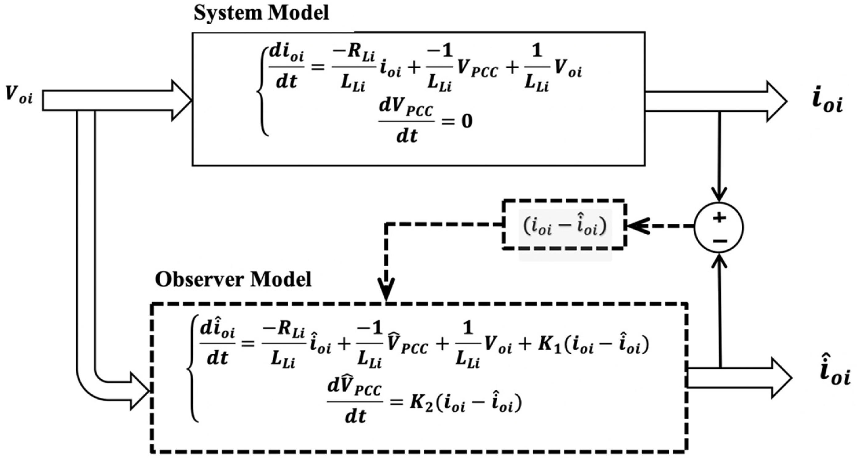
Thus, the differential Equation (5) is used as the real model in the Luenberger observer to estimate the
VPCC of the DC microgrid, as shown in
Figure 6. Here, we consider that the DC bus voltage
changes very slowly compared with the load current; therefore, the voltage derivation is assumed equal to zero in (18).
where
is state variables,
is the control input vector of the system.
Here, all matrices in the state–space equation are obtained from (16), and they are given as follows:
where
A is the system matrix with order 2 × 2;
B is the input matrix of the order 2 × 1; and
C is the output matrix of order 1 × 2.
Since we measure only one output () and do not directly measure , and only have a sensor on the DG output, C is chosen so that the system remains observable while only one of the states () is directly measured.
The state estimation equation for the observer model can be expressed as follows:
Substituting (20) and (17) into (19) then:
The observer model can be expressed as
Thus, the state-space model becomes
where
is the estimated state vector of the order of 2 × 1.
The estimated output vector of the system is given as
The state estimation error of the system can be written as
The error
e(
t) dynamics can be expressed as follows:
To ensure the stability of the observer, the gain must be chosen in a manner such that the real parts of the eigenvalues of the matrix
given bellow is negative.
Through reasonable configuration of pole position, the system will be gradually stabilized. The estimation will converge if the error tends to zero. A trial-and-error method used to determine the Luenberger observer gain in this research study. The system is observable, and can be determined from the pair (A, C) in the observability matrix to ensure fast convergence of the estimation error. Empirically, as shown in
Table 1, we set the observer gain value K
1 = K
2 = 3000 based on initial performance observations and simulated the observer performance in MATLAB/Simulink version R2021b. This tuning was adjusted until the estimated V
PCC enabled balanced power sharing between DG units and maintained the DC bus voltage near 48 V. However, in future work for this study we will implement a pole placement method to select the desired eigenvalues value in the left half-plane, and ensure rapid and robust convergence of the observer error (e) and the stability of the system.
The Luenberger observer control method runs the model in parallel with the existing system as shown in
Figure 6.
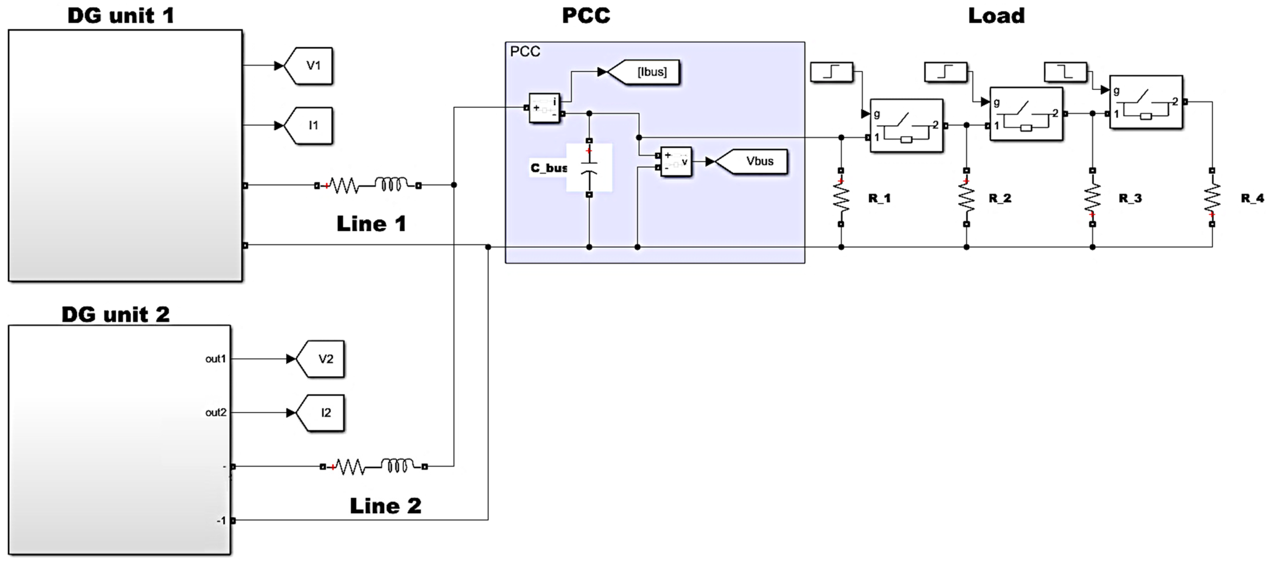
Figure 7 illustrates the MATLAB-Simulink circuit-model developed in this study, which provides a comprehensive simulation framework for an islanded DC microgrid comprising two parallel-connected DG units with line impedance. The model accurately captures the dynamic behavior of load variations by employing paralleled resistive loads controlled by timed switches.
5. Results and Discussions
This section presents simulation and laboratory test results based on the OPAL-RT OP4512 HIL real-time simulation target to validate the effectiveness of the proposed control scheme. The general objective is to achieve accurate load power sharing and regulate the PCC voltage to the nominal value. The performance of the proposed control strategy based on the Luenberger observer technique is also analyzed and compared to the conventional droop control approach.
In this study, we introduced an enhanced control strategy that integrates a Luenberger observer to improve both load sharing and voltage regulation in islanded DC microgrids. The Luenberger observer provides real-time estimates of the PCC voltage and line currents, allowing for precise adjustments to the control inputs of each DG unit. This approach effectively compensates for the adverse effects of unmatched line impedances and dynamic load variations, leading to more accurate and balanced power distribution among parallel-connected DG units. Additionally, by maintaining the DC bus voltage close to its nominal value, the proposed method ensures enhanced voltage regulation across the microgrid.
In this work, the overall DC microgrid system parameters included the input voltage sources, boost converter parameters and line impedances, which are summarized in
Table 1. The control parameters of the DC microgrid are given in
Table 2. Both DG units have equal power ratings and the DC load (
PLoad) is connected at the PCC. The load varies over different time intervals, as presented in
Table 1.
In this study, we evaluate the system’s performance under four distinct operating scenarios. Each scenario represents a specific set of conditions designed to rigorously test the effectiveness of the proposed model. The following sections provide a detailed description of each case and the corresponding test conditions.
The first scenario consists of applying the conventional droop control method to a microgrid with similar power capacities, and equal line impedances. This represents an ideal scenario for illustrating the impact of load variation on the conventional droop control methods. However, in reality, perfectly equal line impedances are unlikely due to various factors influencing the cable parameters.
In the following scenario 2, the same DG power rating is considered, but with unequal line impedance. In this case, the conventional droop control is tested at different time intervals, where the line impedance of the second DG unit is five times that of the first DG unit as indicated in
Table 1.
The third scenario is used to validate that the proposed control strategy under unequal line impedance and load variation, where the impedance of the second line (RL2) is five times that of the first line (RL1).
Finally, the proposed power-sharing control strategy is validated using the OPAL-RT OP4512 hardware-in-the-loop (HIL) real-time simulation target. This scenario demonstrates the performance of the proposed control method under real-time dynamic conditions.
5.1. Simulation Results
In this study, an islanded DC microgrid with two parallel-connected DG units is considered, as illustrated in
Figure 2. The simulation model for the DC microgrid system was implemented in MATLAB/Simulink version R2021B software. The simulation results analyze the load power sharing characteristics between the parallel-connected DG units, as well as the output voltage deviation from the nominal voltage.
- (1)
Scenario 1: Equal DG power rating and line impedances
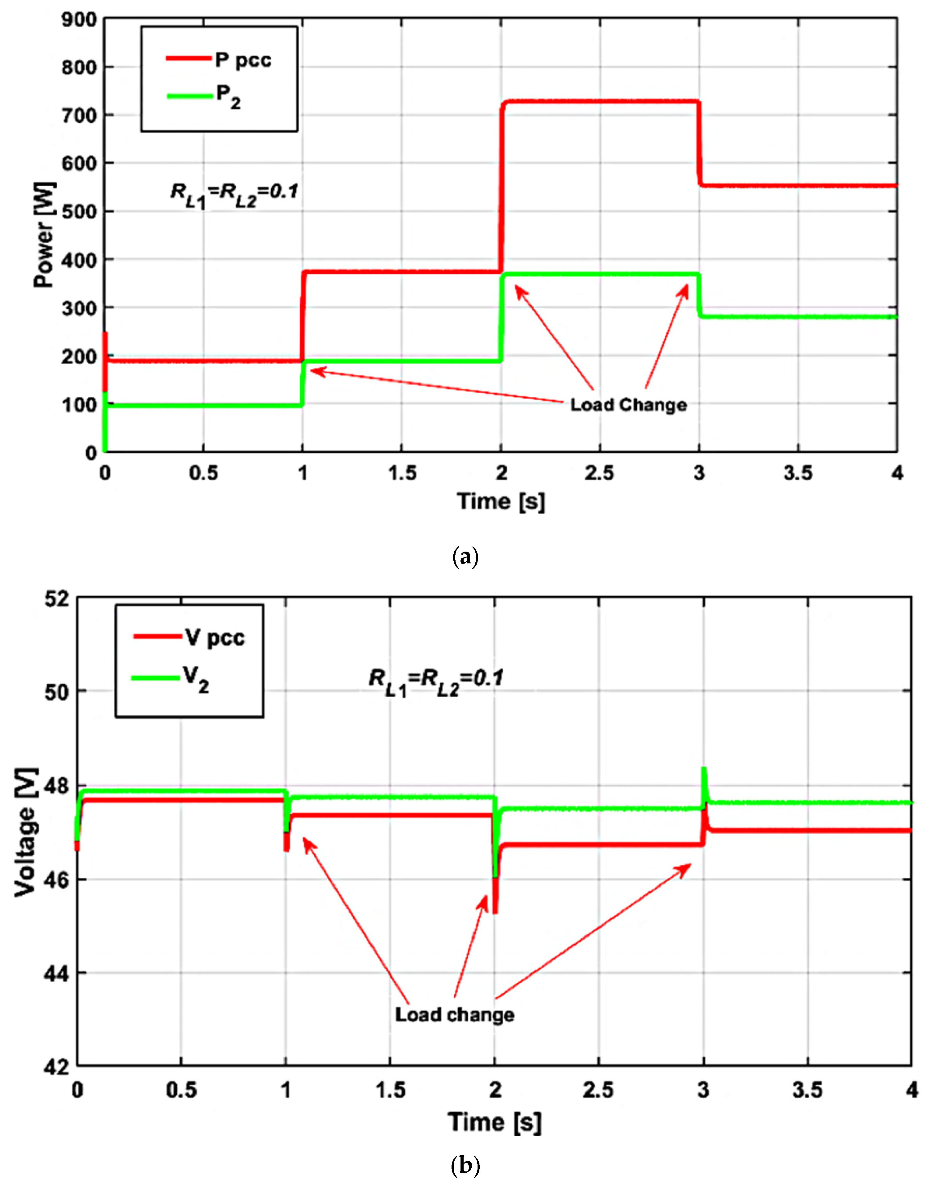
The simulation results of the conventional droop control technique are illustrated in
Figure 8.
Figure 8a illustrates the power consumption at the PCC alongside the individual power contributions delivered by the DG unit to the load. This figure provides a clear depiction of how the coordinated operation of the DG units meets the load demand under the tested conditions. The load power sharing from both DG units are equal as long as the line impedance is the same between the two DG units. (R
L1 = R
L2 = 0.1 ohm).
The output voltage from each DG unit in the conventional droop control method is indicated in
Figure 8b. The PCC voltage at the DC bus is not maintaining the nominal voltage value of 48 V as shown in
Figure 8b.
The load power distribution among the two DG units is not affected by the influence of rise load but it will lead to greater bus voltage deviation as indicated in
Figure 8b. In fact, both DG units participate equally in supplying the total load demand. However, the conventional droop control method introduces certain drawbacks. Specifically, it leads to undesirable deviations in the DC bus voltage and causes transient voltage fluctuations whenever the load in the system changes. These transient effects indicate that droop control alone is insufficient to maintain stable voltage regulation at the DC bus. Droop control alone cannot maintain voltage regulation at the DC bus, necessitating a secondary control level to compensate for voltage deviations.
- (2)
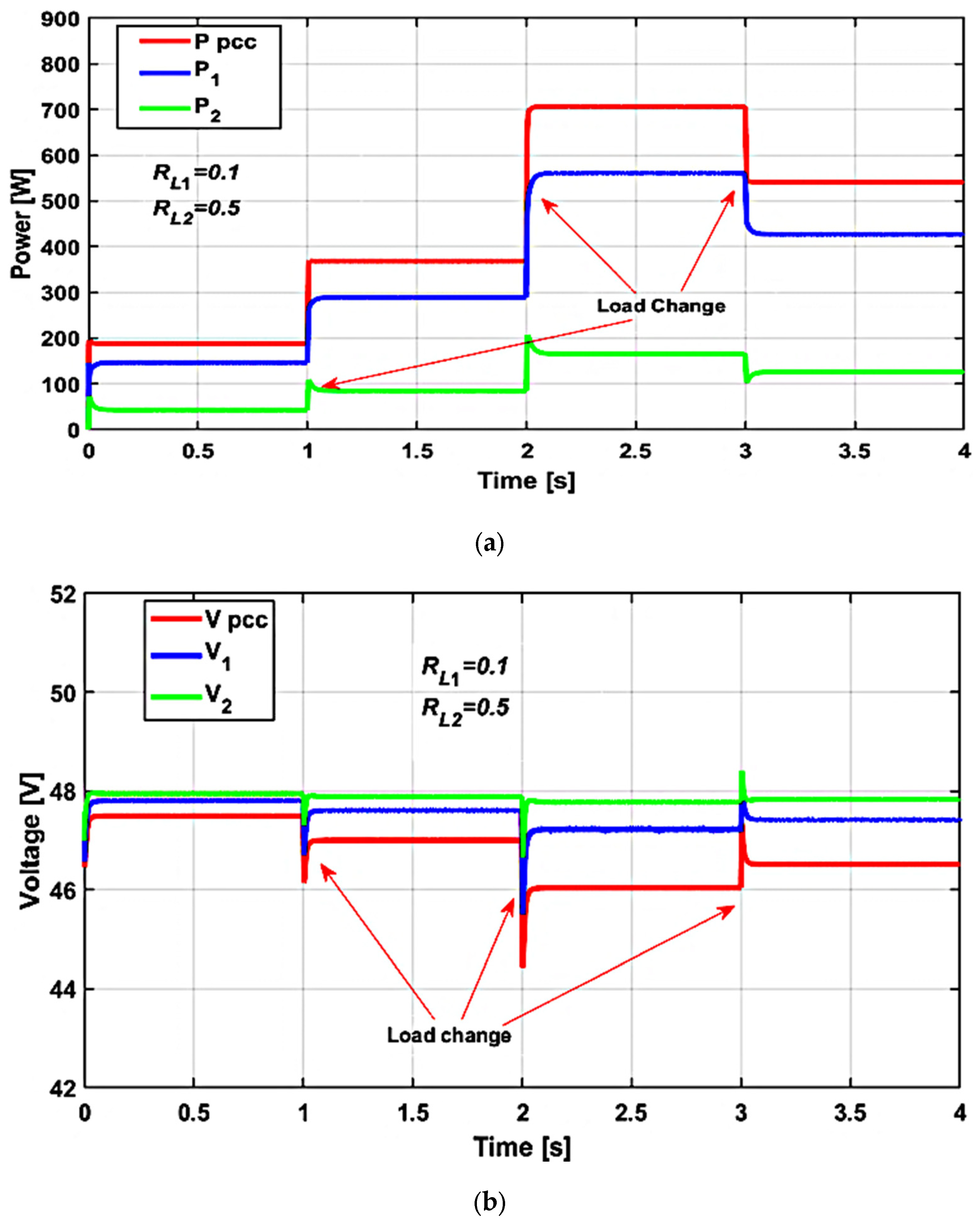
Scenario 2: Equal DG power rating and unequal line impedances for conventional droop control.
In this case, the power sharing performance of a conventional droop control scheme under the influence of unmatched line impedance and load variation at the same time is analyzed. Both DGs have the same droop coefficient.
Figure 9a depicts the power consumed by the overall DC load as well as the power delivered to the load by each distributed generation (DG) unit when using the conventional droop control method. Although the increasing load demand is adequately met, the varying line impedance values cause each DG unit to supply a different amount of power. As a result, the conventional droop control strategy leads to suboptimal load power sharing, with each DG unit outputting a distinct power level due to the influence of the unmatched line impedances.
The voltage profile of the DC microgrid under conventional control methods is indicated in
Figure 9b. As presented in
Figure 9b, the output voltage of DG2 is higher than that of DG1 (i.e., Vo2 > Vo1), which is attributed to the greater line impedance associated with DG2 compared to DG1. Specifically, when the line resistances are R1 = 0.1 Ω and R2 = 0.5, the voltage drop across the second line becomes significantly larger, leading to a voltage imbalance between the two DG units of an approximate 8.3% reduction in voltage.
The conventional control method results in undesirable deviations in the DC bus voltage and induces transient voltage in response to load variations. Notably, the DC bus voltage at the load deviates from its nominal value of 48 V. Each time the load increases, a voltage drop is observed at the PCC. Moreover, the conventional strategy does not ensure accurate power sharing among the two DERs, primarily due to its sensitivity to line impedance mismatches and dynamic load changes.
- (3)
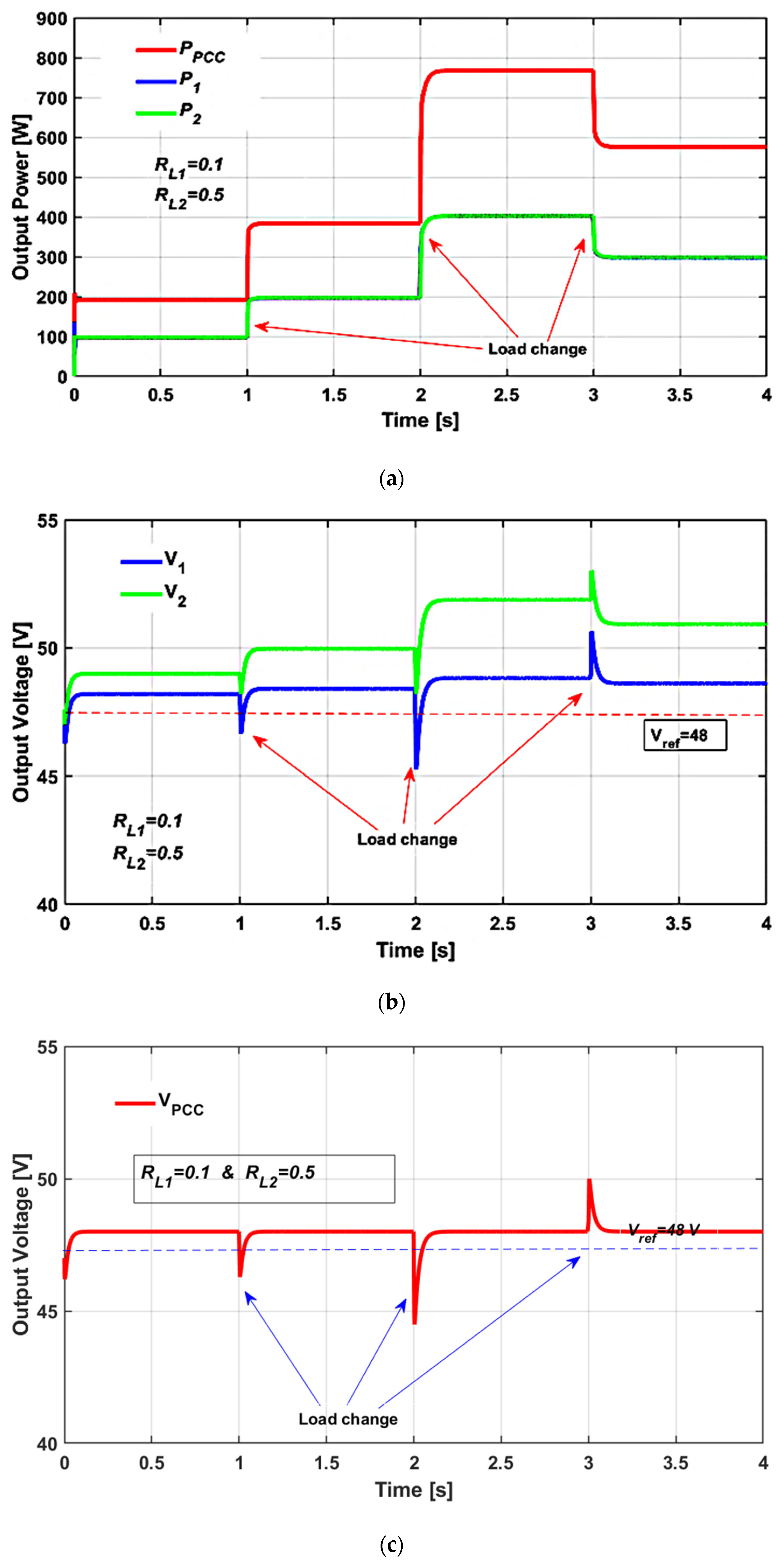
Scenario 3: Equal DG power rating and unequal line impedances for the proposed control method
The performances of the proposed control strategy using the Luenberger observer technique considering unmatched line impedance and load variation are presented in
Figure 10. As illustrated in
Figure 10a, the proposed method maintains equal power sharing between the two distributed generation (DG) units, regardless of changes in the load. This demonstrates that the controller effectively compensates for line impedance mismatches, ensuring balanced power contribution from each DG unit. Unlike the conventional droop-based approach, which suffers from unequal power distribution in the presence of line impedance variations, the proposed observer-based control strategy consistently achieves the primary objective of accurate load power sharing.
Figure 10b,c presents the individual output voltage of each DG unit and the PCC voltage of the islanded DC microgrid, respectively. As shown in
Figure 10c, the proposed control strategy successfully maintains the DC bus voltage at the PCC close to its nominal value of 48 V, despite various load changes occurring within the system. This highlights the controller’s ability to effectively regulate the bus voltage under dynamic operating conditions. The voltage regulation of each DG unit is still the within allowable limit of voltage deviation.
While the Luenberger observer-based control scheme significantly enhances performance over traditional droop control, and maintains stable DC bus voltage regulation, transient effects and voltage fluctuations persist in individual DG outputs and PCC voltage. Therefore, an additional secondary control method is required to stabilize voltage and mitigate transient influences.
The simulation results show that the proposed control strategy using the Luenberger observer method allows the two distributed generation (DG) units to achieve equal power sharing, and also achieves stable voltage regulation across the entire microgrid, even in the presence of unequal line impedances and fluctuating load demands. The proposed observer control method outperforms the traditional droop control technique in both power sharing and voltage regulation, particularly under varying load conditions over time.
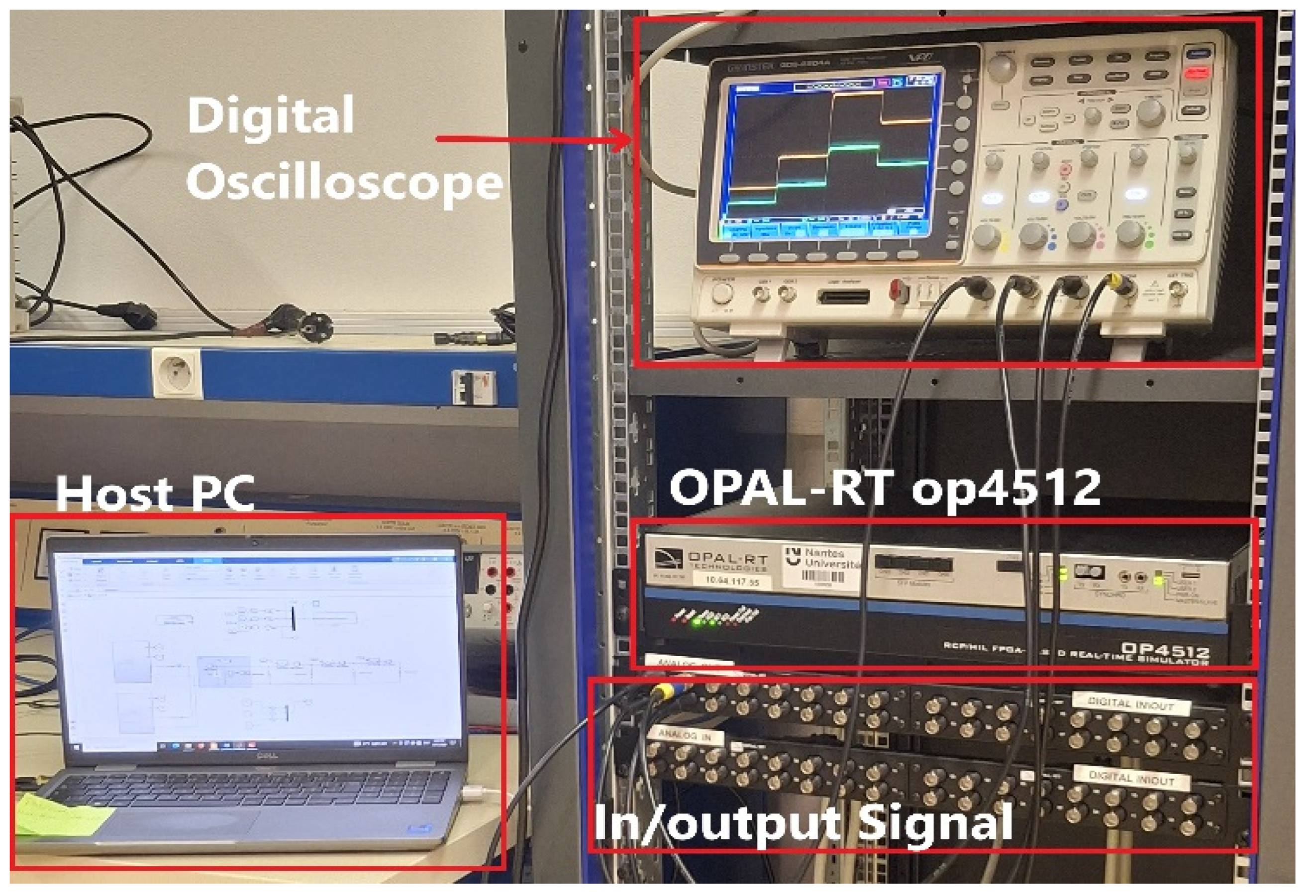
5.2. Laboratory Real-Time Simulation Results
To further validate the power-sharing performance and practical applicability of the proposed control strategy, hardware-in-the-loop (HIL) laboratory experiments were conducted using the OPAL-RT OP4512 real-time simulation platform. The experimental results offer a more accurate representation of system behavior and demonstrate the effectiveness of the proposed approach in ensuring balanced power sharing and voltage regulation in the presence of load variations and line impedance mismatches. This system provides the computational capability necessary for real-time processing, and hardware-in-the-loop (HIL) testing. The experimental setup comprises a host PC running RT-LAB v2024.3.3.51 software, a digital oscilloscope, TCP/IP Ethernet cables, target nodes, and input/output boards, as can be seen in
Figure 11.
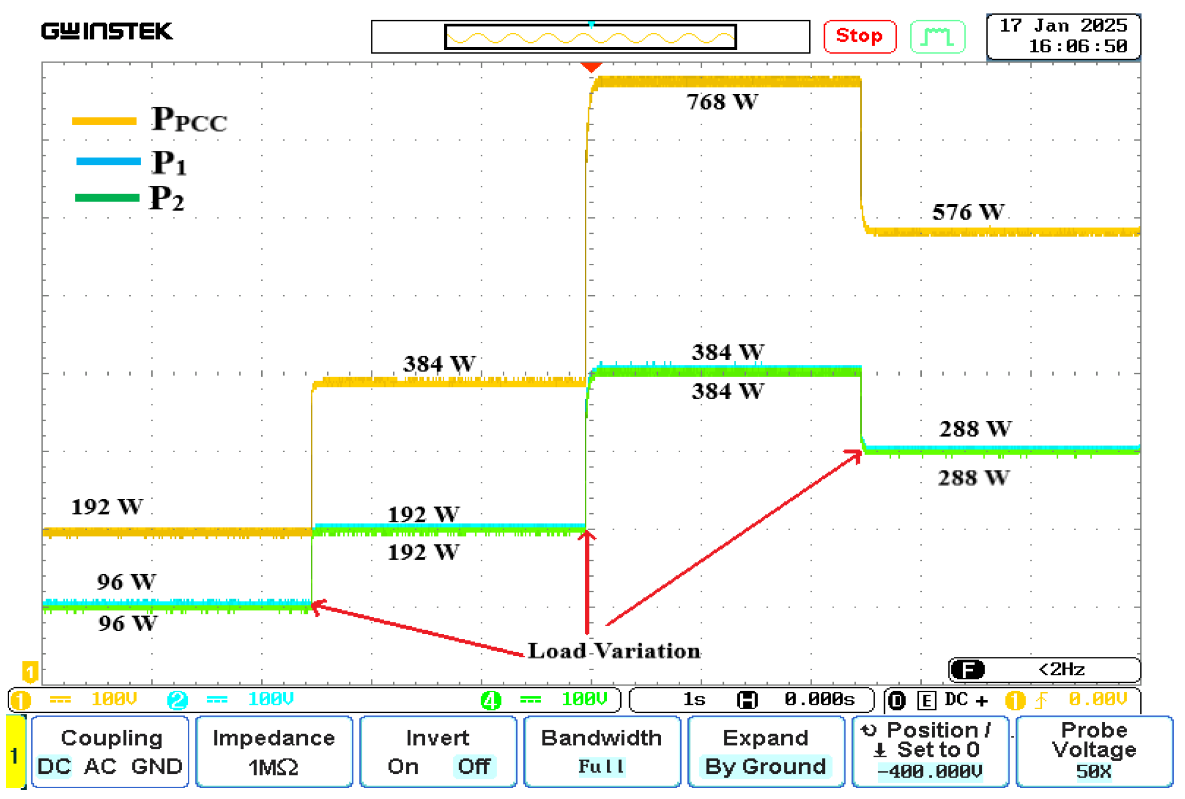
Figure 12 illustrates the power consumed by the load at the PCC and the power delivered to the load by each DG unit. The load power sharing between the two DG units are equal considering unmatched line impedance and load variation.
Figure 12 shows that each DG delivers an equal amount of power to the load every time the load changes; even at t = 5 s the PCC load increases to 768 W, and each DG unit delivers 384 W to the load. This indicates the successful achievement of balanced power sharing. The proposed control system achieves the objective of equal power sharing even if the line impedance difference between two DG units is ten times higher, as shown in
Figure 12. Both mismatches in line impedance and load variation have no impact on the proposed control method to achieve accurate power sharing.
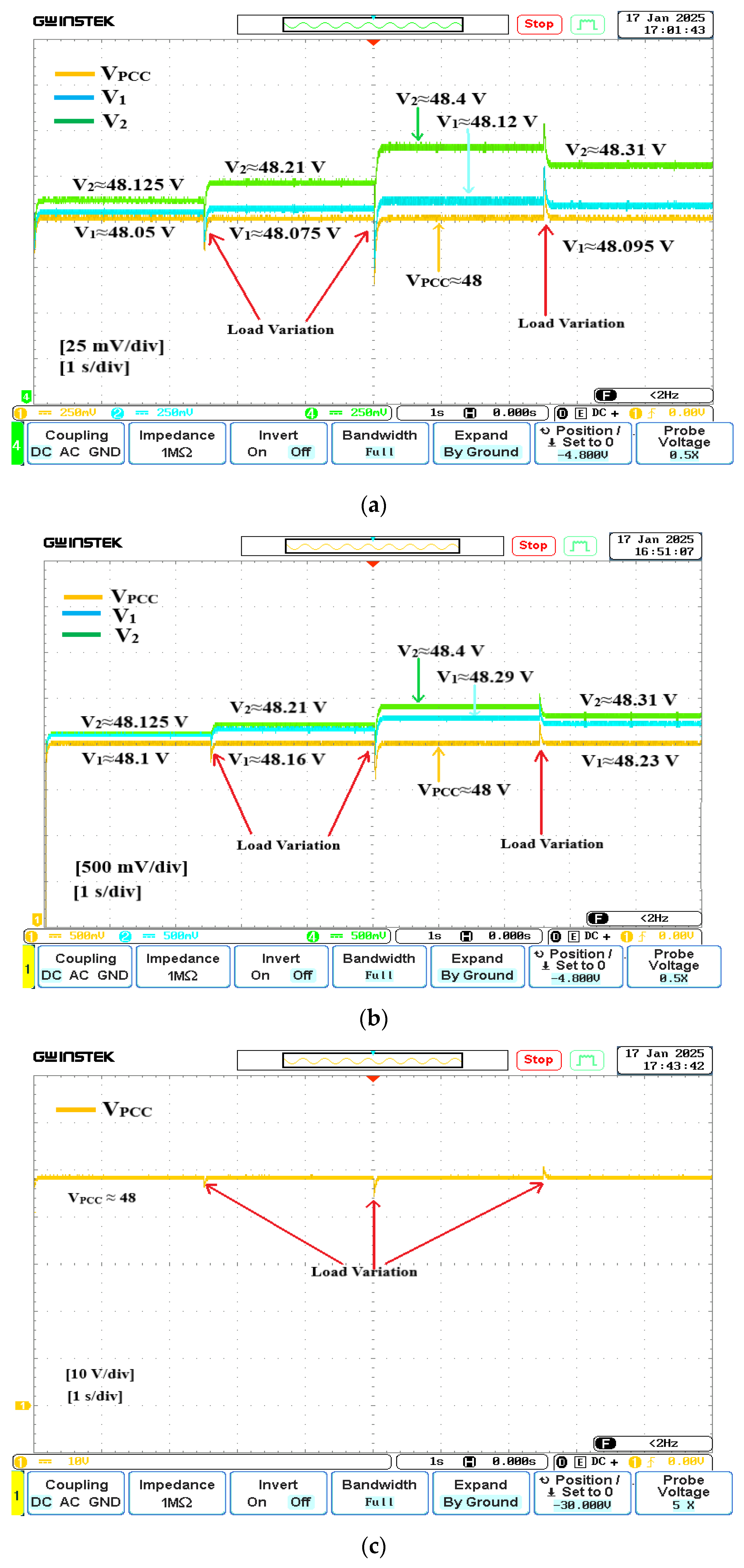
Figure 13 presents the PCC voltage and output voltage of the two DG units in the islanded DC microgrid. However, the output voltages from each DG unit are not identical as observed in
Figure 13a,b. As the load increases, the individual output voltage of each DG unit diverges further from the nominal voltage.


 ,
, 
