Article

The Pole-to-Ground Fault Current Calculation Method and Impact Factor Investigation for Monopole DC Grids

State Grid Sichuan Electric Power Supply Company Meishan Branch, Meishan 620860, China
*
Author to whom correspondence should be addressed.
Electronics 2025, 14(6), 1067; https://doi.org/10.3390/electronics14061067
Submission received: 9 February 2025 / Revised: 27 February 2025 / Accepted: 27 February 2025 / Published: 7 March 2025

Abstract

:
Flexible DC grids are an important technological means for optimizing power supply structures and promoting energy transition. However, as a system with low inertia and weak damping, the flexible DC grid inherently faces challenges, such as rapid rising of fault currents, vulnerability to significant damage, difficulty in fault interruption, and with regard to the poor overcurrent-withstanding capabilities of power electronic devices. To address these issues, this paper proposes a method for calculating the single-pole ground fault current in a symmetrical monopolar DC grid, and further introduces a matrix exponential calculation method. This method enables quantitative analysis of the influence of various component parameters on the fault current, taking into account the dynamic characteristics of both the faulted and healthy poles in the DC system. The results demonstrate the high accuracy of this calculation method. The analysis reveals that the inductance of the faulted branch has the greatest impact on the fault current, while the inductances of the adjacent outgoing lines also have a certain influence. In contrast, the inductances of lines not adjacent to the faulted branch have minimal impacts on the fault current. Furthermore, the grounding electrode parameters of the converter station connected to the faulted branch exert the most significant influence on the fault current, with the grounding electrode parameters of neighboring converter stations also showing a notable effect. This indicates that the fault current is impacted by the topology of the nearby DC grid, but is not affected by the fault currents at remote converter stations.

1. Introduction

China boasts a vast territory and a long coastline, endowing it with abundant renewable energy resources [1,2]. Till now, the installed capacity of hydropower in China has exceeded 427 million kilowatts, with a cumulative grid-connected capacity of 530 million kilowatts for wind power and 890 million kilowatts for photovoltaic power, all ranking first in the world [3]. To adapt to the profound changes in the future energy landscape, it is necessary to construct new power integration and transmission corridors to facilitate the intensive development and optimal allocation of large-scale energy resources [4,5].
Currently, research on multi-terminal HVDC transmission and DC grid technology is gaining increasing depth both domestically and internationally [6]. The CIGRE has established six working groups to conduct research on feasibility, planning, DC converter models [7,8], topologies, power flow control, control and protection, and reliability of DC grids. Europe has proposed the concept of a Super Grid plan, utilizing DC grid technology to integrate offshore wind power from the North Sea and the Baltic Sea, as well as photovoltaic power from North Africa and the Middle East. The United States has also introduced the “Grid 2030” initiative, aiming to construct a backbone grid based on advanced HVDC transmission technology to meet the significant demands of new energy development and smart grid interconnection [9].
Riding on the wave of national energy reform policies, China has successfully constructed the Nan’ao ±160 kV multi-terminal flexible HVDC (High Voltage Direct Current) demonstration project, the Zhoushan ±200 kV multi-terminal flexible HVDC project, and the Zhangbei ±500 kV flexible HVDC grid demonstration project. In the future, China will develop a large-scale and complex hybrid AC-DC (Alternating Current–Direct Current) grid. To ensure the safe and reliable operation of this AC-DC grid, further research is indispensable. The Modular Multilevel Converter based Multi-Terminal Direct Current System (MMC-MTDC) has become an important research direction in HVDC transmission due to its high reliability [10].
As the DC grid expands, the frequency of fault occurrences rises. When a line fault triggers the action of circuit breakers or changes the power injected into the DC grid by converter stations, the power flow is redirected to normal branches within the grid. This redirection may lead to line overloading and even cascading tripping incidents, exacerbating the fault. Therefore, it is crucial to calculate the fault current in the DC grid and analyze the influencing factors [11,12].
However, unlike AC systems, flexible DC grids also have limitations that hinder their development, such as fault currents that lack zero-crossing points and rise rapidly, as well as grid equipment with poor overcurrent withstand capability. Additionally, in DC transmission grids, pole-to-ground faults have the highest probability of occurring [13].
The MMC HVDC system possesses the capability to reverse power flow without changing voltage polarity, enabling the construction of multi-terminal flexible DC grids [14]. However, as flexible DC grids expand in scale and voltage levels increase, the inherent weak damping characteristics of flexible DC systems lead to rapid rises in fault current and large overcurrent amplitudes following short-circuit faults, severely limiting the application and promotion of flexible DC grids.
Damping characteristics are a crucial indicator for studying the dynamic response of a system under disturbances. Analyzing the damping characteristics of MMC-based flexible DC grids can provide guidance for investigating the dynamic behavior of short-circuit currents. Nevertheless, existing research primarily focuses on the calculation and suppression methods of short-circuit currents in flexible DC grids. An equivalent circuit method is widely used for calculating short-circuit currents in flexible DC grids [15]. In this method, MMC converter stations are equated to series capacitor–inductor circuits, and the entire flexible DC grid is modeled as a linear circuit. By constructing a short-circuit current discharge loop and solving differential equations, the short-circuit current is calculated [16,17]. The equivalent circuit method overlooks the internal dynamic characteristics of MMC converter stations during faults and fails to capture the damping characteristics of flexible DC grids.
Regarding the suppression of short-circuit currents in flexible DC grids, current research mainly involves improving the internal topology of MMC converter stations [18] and installing novel current-limiting devices [19] to mitigate short-circuit currents. However, these studies do not analyze the influence of the inherent system characteristics of MMC-based flexible DC grids on short-circuit currents, nor do they propose methods for suppressing fault currents from a system-wide perspective of flexible DC grids.
To investigate the factors influencing fault current distribution under different power source characteristics, considering the impact and contribution of the AC system to the DC short-circuit current is urgent. This entails conducting detailed research on the mechanism by which AC power sources with varying characteristics affect DC short-circuit current, as well as developing methods for calculating the contribution to the short-circuit current. This research lays a theoretical foundation for system fault analysis and protection design.
Study [20] establishes an equivalent model for capacitor discharge on the DC side for the case of an inter-pole short-circuit fault in a two-terminal DC system and calculates the fault current equivalently, but it does not account for the current feed from the AC system. Study [16] constructs an equivalent circuit network model for a bipolar flexible DC grid and adopts a general method for calculating inter-pole short-circuit fault current in DC grids. It formulates the original matrix equations for the flexible DC grid prior to the fault occurrence and adjusts the matrix equations for the grid post-fault, markedly enhancing computational efficiency and facilitating a quantitative assessment of the transient behaviors of short-circuit current in flexible DC grids across diverse operational scenarios. Nevertheless, it falls short in examining the inherent connection between fault current and various parameters. Reference [21] investigates the effect of the AC side on the submodule arm current by treating the AC-side input as equivalent to a three-phase short-circuit current, whereas the DC-side line fault current is computed solely as capacitor discharge. On the other hand, Reference [22], which accounts for both AC-side input and converter control, employs a recursive formula methodology to compute short-circuit current from the viewpoint of converter energy, leading to more precise short-circuit current estimations. However, it does not clearly articulate the influence of AC-side input on fault current.
In summary, current research on DC faults seldom provides a comprehensive analysis of the factors influencing pole-to-ground fault current in DC grids. Additionally, the current feed from other converter stations is often neglected in fault current calculations, leading to certain errors. This is detrimental to the accurate selection, precise control, and setting calculations of DC equipment. To address the problem, this paper proposes the accurate pole-to-ground fault currents calculation method in multi-terminal monopole DC grids, and the impact factors on such type of fault current are also investigated, which can be helpful with the DC grids safety operation and protection.
The novelties of this paper can be summarized as follows:
(1)
An accurate pole-to-ground fault current calculation method in multi-terminal monopole DC grids is proposed, based on a simplified RLC-equivalent model, where the accuracy and calculation efficiency can be both guaranteed.
(2)
Based on the proposed method, varied components and their parameters’ impact on pole-to-ground fault currents have been investigated. And the most influential components are also discovered.

2. The Pole-to-Ground Fault Characteristic in Symmetrical Monopole DC System and Equivalent Circuit

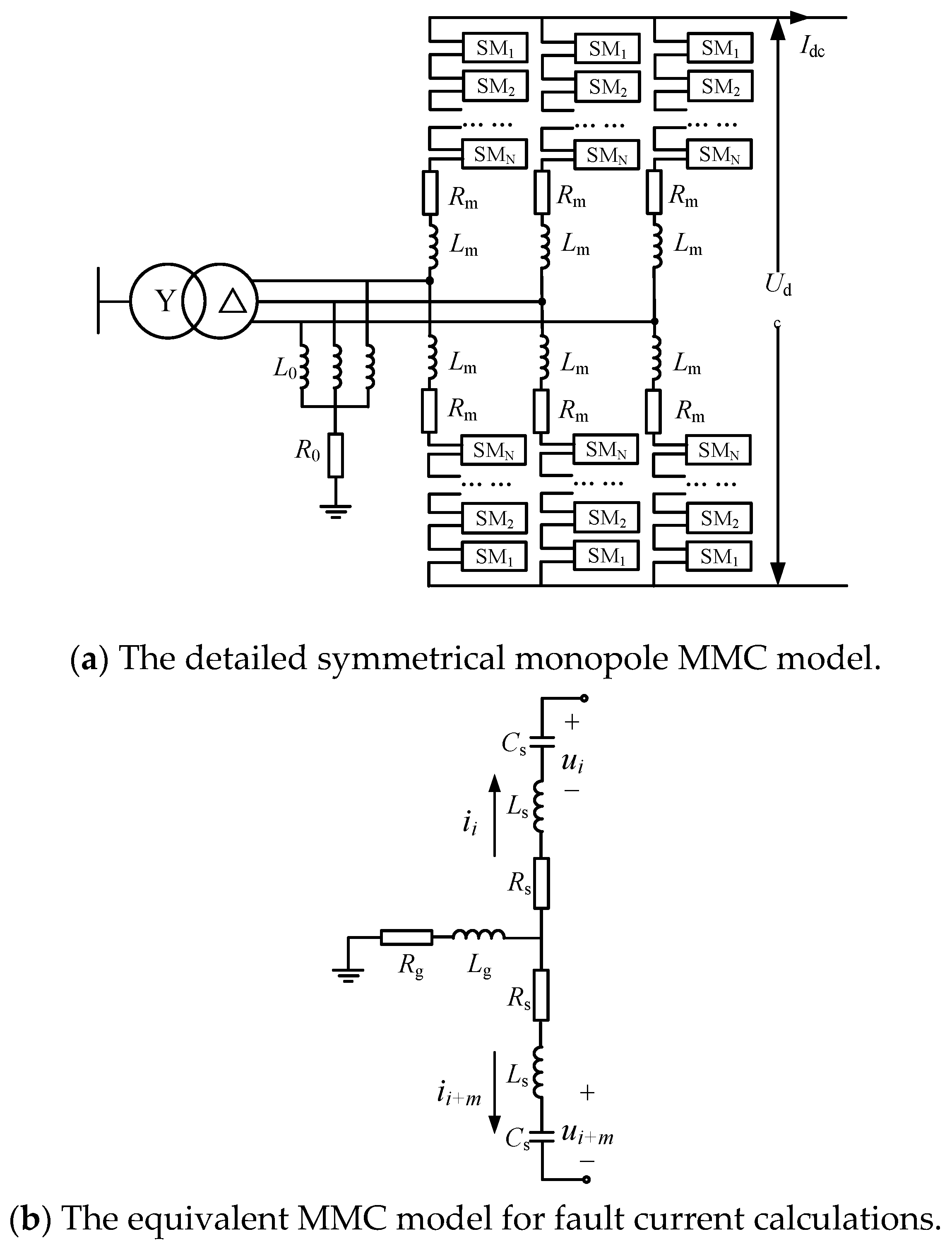
2.1. Symmetrical Monopole DC Converter

A ground fault on the DC bus, specifically a pole-to-ground fault, is a common occurrence in high-voltage direct current (HVDC) transmission systems that employ modular multilevel converters (MMCs). Investigating the characteristics of such faults carries substantial engineering significance for fault diagnosis, protection strategy design, and the optimization of relevant system parameters. The principal consequence of a pole-to-ground fault is that the voltage of the unaffected pole surges to double its rated level. Concurrently, a substantial DC offset appears in the AC-side voltage, which may exceed the transformer’s withstanding capability. Owing to the adoption of a low-current grounding approach, the fault current associated with a pole-to-ground fault is considerably lower than that of a pole-to-pole short-circuit. In practical engineering practice, if a pole-to-ground fault arises and the converter station does not trip, the system retains the ability to operate normally. In MMC-based multi-terminal HVDC (MMC-MTDC) transmission systems that utilize overhead lines, the transient fault characteristics exhibit marked variations depending on the grounding method implemented during a pole-to-ground fault event.
Currently, there are three main grounding methods for symmetrical monopolar converter connections: type (a): grounding the valve side of the converter transformer through a star reactor via a resistor; type (b): grounding the neutral point of the converter transformer via a resistor (for both delta/star-connected converter transformers); type (c): grounding the DC side through two clamping resistors. The specific configuration is shown in Figure 1.
In type (a), the reactor Lg and the resistor R are used to limit the rate of increase and the steady-state value of the fault current, respectively. Type (b) is typically used in low-voltage systems and is characterized by using a star-connected winding on the valve side of the converter transformer instead of a reactor to save on grounding equipment, with a relatively high grounding resistance. The DC-side fault characteristics of these two grounding methods are similar, but during a grounding fault, using the second method results in a large fault current flowing through the transformer’s secondary side, which increases the difficulty of transformer manufacturing. Type (c) introduces additional losses, as the two series-connected DC resistors can cause a voltage imbalance between the positive and negative poles due to resistance deviations. However, in the event of a pole-to-ground short-circuit fault on the DC line, it does not form a discharge path with the converter submodule capacitors, so no fault current is generated in the converter transformer valve group. In large-scale, high-voltage MMC-MTDC systems, employing the latter two grounding methods would exacerbate their inherent drawbacks. The grounding connection on the transformer side facilitates the flow of zero-sequence current, rendering Type (a) the sole viable option for MMC-MTDC applications. Indeed, this grounding scheme has found widespread adoption in numerous real-world engineering projects.

2.2. The Equivalent Model for Symmetrical Monopole Converter

The probability of a direct pole-to-pole short-circuit fault occurring in a DC transmission system is very low; typically, such faults are indirectly caused by simultaneous grounding faults on both poles. When a pole-to-pole short-circuit fault occurs in a DC transmission line, the capacitors in the MMC submodules discharge rapidly, leading to a swift increase in arm currents and line currents. According to reference [23], the fault current within the first 10 ms after the fault occurs is primarily formed by the discharge of submodule capacitors, with almost no influence from the AC grid. Given that DC circuit breakers have the capability to interrupt fault currents within a few milliseconds and that the configuration of smoothing reactors can slow down the rate of fault current rise, this section analyzes the fault current within 10 ms after a pole-to-pole short-circuit fault occurs in a DC line, based on the premise that the converter station remains unblocked.
Considering the grounding method where the star-connected reactor on the AC side of the pseudo-bipolar converter is grounded through a large resistor, the MMC is simplified into an RLC equivalent circuit, as shown in Figure 2.
In the figure, Rm represents the sum of the on-state resistances of all IGBT modules, Lm denotes the arm inductance, Rg is the grounding resistance on the AC side, and Lg is the equivalent inductance of the grounding star reactor. Rs, Ls, and Cs are the equivalent resistance, equivalent inductance, and equivalent capacitance of a single pole, respectively, which can be calculated using the following formulas:
R s = R m 3 ,   L s = L m 3
Assuming that the capacitor voltages in the submodules are balanced and all equal to USM, the total energy stored in the capacitors of the positive or negative three-phase arms can be derived based on the principle of energy conservation as follows:
E = 3 × N SM × 1 2 C SM U SM 2 = 1 2 C s 1 2 N SM U SM 2
In the equation, CSM represents the capacitance value of a single submodule, and NSM denotes the number of submodules in each arm. The expression for the equivalent capacitance, Cs, can be calculated from Equation (2) as follows:
C s = 12 C SM N SM

3. The Fault Current Calculation Method for Symmetrical Monopole DC Grids

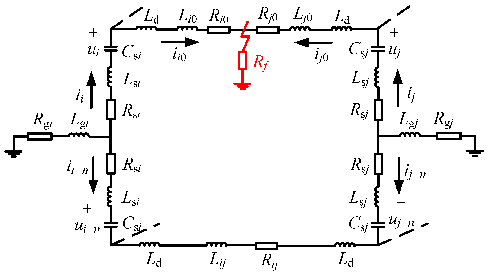
3.1. The Calculation Model Based on the Equivalent Model

Despite the variations in DC grid topologies, a consistent KVL (Kirchhoff’s Voltage Law) equation for DC grids can be established utilizing the MMC (Modular Multilevel Converter) equivalent circuit and the streamlined DC line model depicted in Figure 2b. To streamline theoretical examinations, the process of determining the pole-to-ground fault current can be broken down into two phases: initially, a baseline state-space equation is derived from the KVL differential equation under normal operating conditions; subsequently, upon the occurrence of a pole-to-ground fault on a DC line, the pertinent parameters in the state-space equation are adjusted to account for the faulted branch, and an extra fault equation is integrated to formulate the fault state-space equation. The following sections will elaborate on this computational approach.
When calculating the pole-to-ground fault current, the dynamic characteristics of the unimpacted pole in the MMC are often neglected. As a result, the derived differential equations do not account for the charging and discharging cycles of the submodule capacitors in the healthy pole, leading to inaccurate computations. In this section, we will simultaneously take into account the dynamic behaviors of both the positive and negative poles of the MMC following a fault, as Figure 3 shows, to ensure precise calculation of the pole-to-ground fault current.

3.2. Mathematical Equations Before Fault

In the DC grid, there are m converter stations and l transmission lines. The currents in each line for both the positive and negative poles, as well as the voltages at the positive and negative poles of each converter, are designated as state variables. The discharge currents at the positive and negative poles of the converters can be obtained by multiplying the incidence matrix with the line currents. The state variables are listed in the order of positive poles first, followed by negative poles.
The discharge currents of the converter, line currents and equivalent capacitor voltages are as Equations (4) to (6) show, respectively.
i c 0 = i 1 i 2 i m + 1 i m + 2 i 2 m T
i 0 = i 12 i i j T
u 0 = u 1 u 2 u m + 1 u m + 2 u 2 m T
The vector of currents i c 0 = i 1 i 2 i m + 1 i m + 2 i 2 m T can be obtained by multiplying the line current vector i with the incidence matrix A0, which describes the topological relationship between the lines and the converters; i.e.,
i c 0 = A 0 i 0
The incidence matrix A0 is a 2 m × l matrix, and its columns are constructed according to the following rule:
a i k = 1 node   i   is   branch   k   s   starting   point 1 node   i   is   branch   k   s   ending   point 0 node   i   does   not   belong   to   branch   k
since the direction of the positive electrode discharge current is the same as the preset direction, and similarly, the direction of the negative electrode discharge current also aligns with the preset direction.
C c i d u i d t = i i C c i d u i + m d t = i i + m
Due to the opposite directions of the positive and negative electrode currents, it is necessary to define a diagonal matrix M with dimensions of 2 m × 2 m to adjust the current directions. The elements in M are defined as follows:
m i i = 1 n o d e   i   i s   p o s i t v i c e   p o l e   n o d e 1 n o d e   i   i s   n e g a t i v e   p o l e   n o d e
The system of differential equations for line currents and the system of equations for capacitor discharge can be represented in matrix form as follows:
B 0 u = R 0 i 0 + L 0 d i 0 d t
C d u d t = M i c 0
where B0 is a matrix of size l × 2 m.
B 0 = A 0 T M
By substituting Equation (7) into Equation (12), we obtain:
C d u d t = M i c 0 = M A 0 i 0 = P 0 i 0
Both R0 and L0 are l × l matrices, representing the loop resistance matrix and the loop inductance matrix, respectively. The rules for constructing these matrices are as follows: The diagonal elements of R0 include all the resistances that the loop current flows through. Specifically, for branch k (with the positive pole labeled as ij and the negative pole labeled as (i + m)(j + m)), the corresponding diagonal element in R0 is r k k = R i + R c i + R i j + R c j + R j .
Specifically, the distribution of grounding resistances, the equivalent resistances of the converter positive poles, and the equivalent resistances of the converter negative poles in the off-diagonal elements are presented in Table 1, Table 2 and Table 3, respectively.
The rule for listing the elements in L0 is the same as that for R0, and C is a diagonal matrix composed of the equivalent capacitances of the positive and negative poles of each converter, which is C = diag[Cc1 Cc2Ccm Cc1 Cc2Ccm].
By combining Equation (11) with Equation (14), we can obtain the state equation of the DC grid before the fault.
d d t i 0 u 0 = L 0 1 R 0 L 0 1 B 0 C 1 P 0 0 i 0 u 0

3.3. The Revised Mathematical Equations After Fault

After the fault, the fault line ij is split into faulty branches i0 and j0, while the other branches remain unchanged. Therefore, only the elements in the matrices related to the faulty branches need to be modified.
Correspondingly, after the fault, the line current iij is split into ii0 and ij0, namely i = i 12 i i 0 i j 0 T . The discharge current vectors of the converter’s positive and negative poles, as well as the equivalent capacitance voltage vector, remain unchanged.
The relevant column corresponding to iij in the incidence matrix A is modified to two columns related to ii0 and ij0. The M matrix, which is associated with the discharge direction of the converter’s positive and negative pole capacitances, remains unchanged before and after the fault. The capacitance matrix C also remains unchanged.
After the fault, an additional branch is added to the DC grid. Consequently, both the resistance matrix R and the inductance matrix L are augmented by one row and one column. The row and column previously corresponding to line ij in the original matrices are modified to reflect the resistance/inductance elements associated with i0 and j0, while the other elements in the matrices remain unchanged. The method for listing the matrix elements remains the same as before the fault. In the fault loop equation in R, the positions corresponding to the fault branch currents ii0 and ij0 need to include the fault resistance Rf.
If branch k is the faulty branch, the corresponding diagonal element is r k k = R i + R c i + R i 0 + R f .
The state equation of the DC grid after the fault is finally revised as follows:
d d t i u = L 1 R L 1 B C 1 P 0 i u

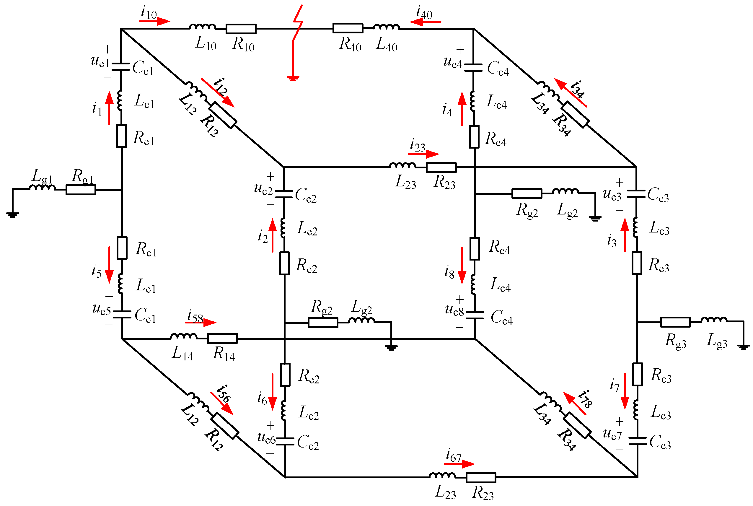
4. Verification of Pole-to-Ground Fault Current Calculation in Monopole DC Grid

Taking a four-terminal symmetrical monopolar DC grid as an example, its specific parameters are listed in Table 4, and its equivalent model is shown in Figure 4 and Figure 5.
The system parameters in 4-terminal DC grid are presented in Table 5, where the smooth conductor is for fault current limitation, and it is considered into the line inductance value when calculations are implemented.
Assuming a positive pole ground fault occurs at the midpoint of line L14 at 1.0 s, we solve for the fault current within the first 10 ms after the fault. As shown in the comparison results in Figure 5 and Figure 6, the proposed method exhibits high computational accuracy in calculating the monopolar ground fault current and can be used for subsequent analysis of factors influencing the fault current.

5. Pole-to-Ground Fault Current Impact Factors Investigation

After the verification of accuracy for the fault current calculation method, this section will investigate the impact factors of the fault current in symmetrical monopole DC grids, where the most influential element will be elucidated.

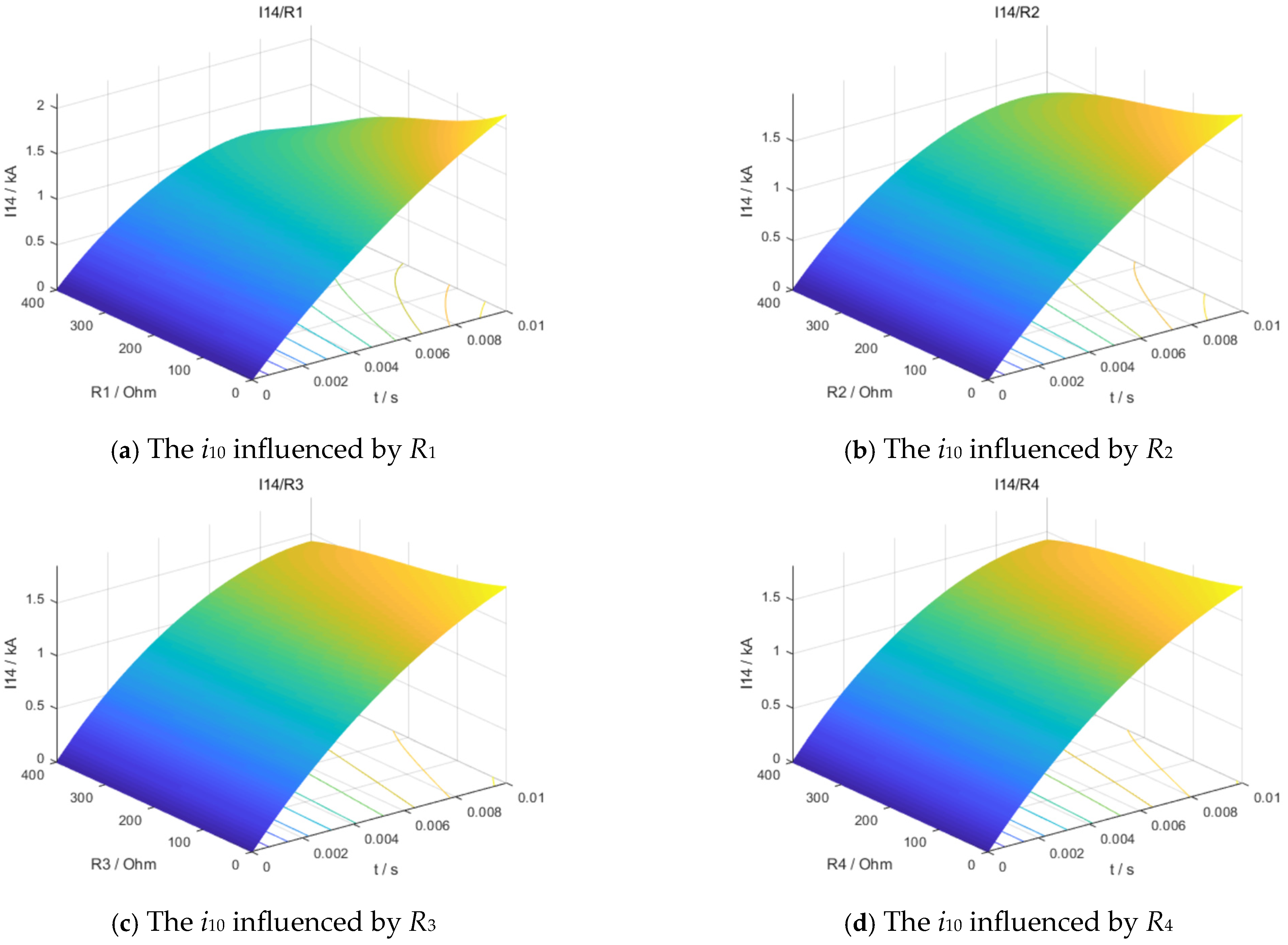
5.1. The DC Line Parameters’ Impact Analysis

Firstly, the influence of the resistance and inductance values of each line on the fault current i10 was analyzed. As shown in Figure 7, the inductances of the fault branch (L10 and L40) have the most significant impact on the fault current, while the inductance of the adjacent outgoing line to the fault branch (L12) also exhibits a noticeable influence. However, the inductance of the line that is not adjacent to the fault branch (L23) has almost no effect on the fault current.

5.2. The Grounding Electrode Parameters’ Impact Analysis

The influence of grounding electrode resistance, and inductance values at various converter stations on the fault current i10, was analyzed. As illustrated in Figure 8 and Figure 9, the grounding electrode parameters (R1, L1) of the converter station connected to the fault branch have the most significant impact on the fault current, while the grounding electrode parameters (R2, L2) of adjacent converter stations also exhibit a notable influence.

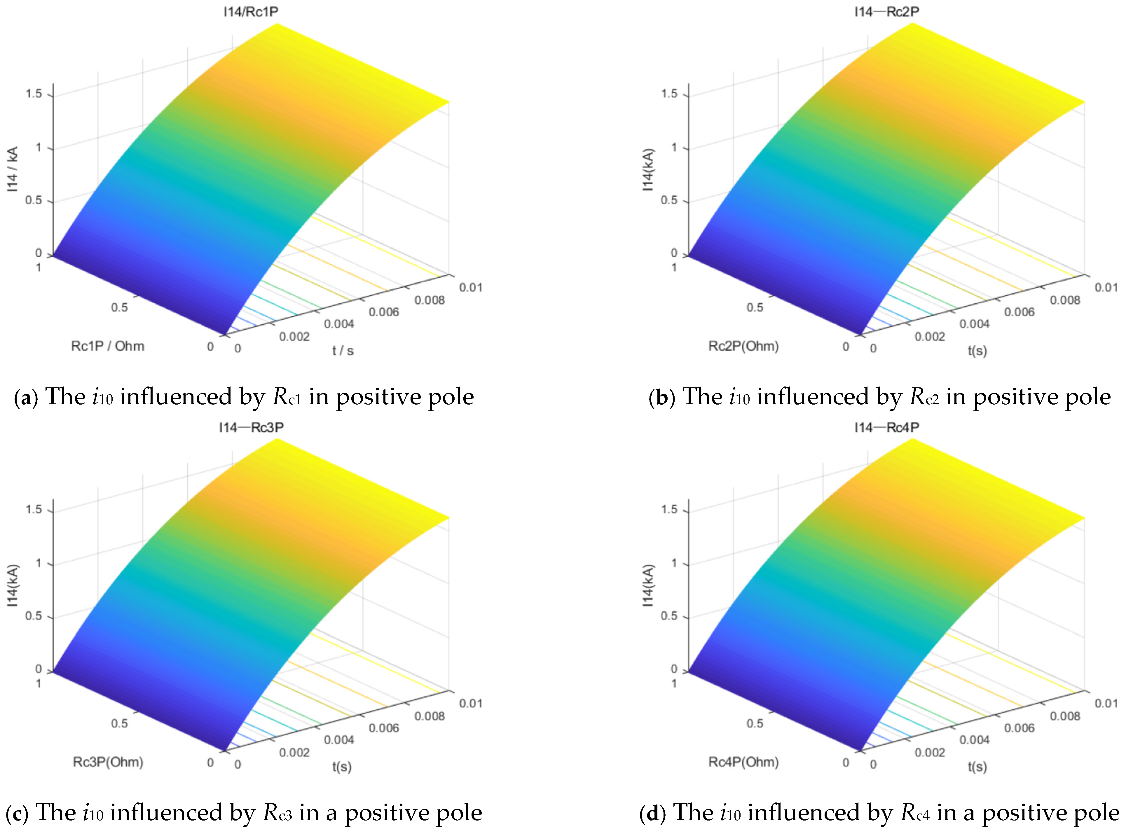
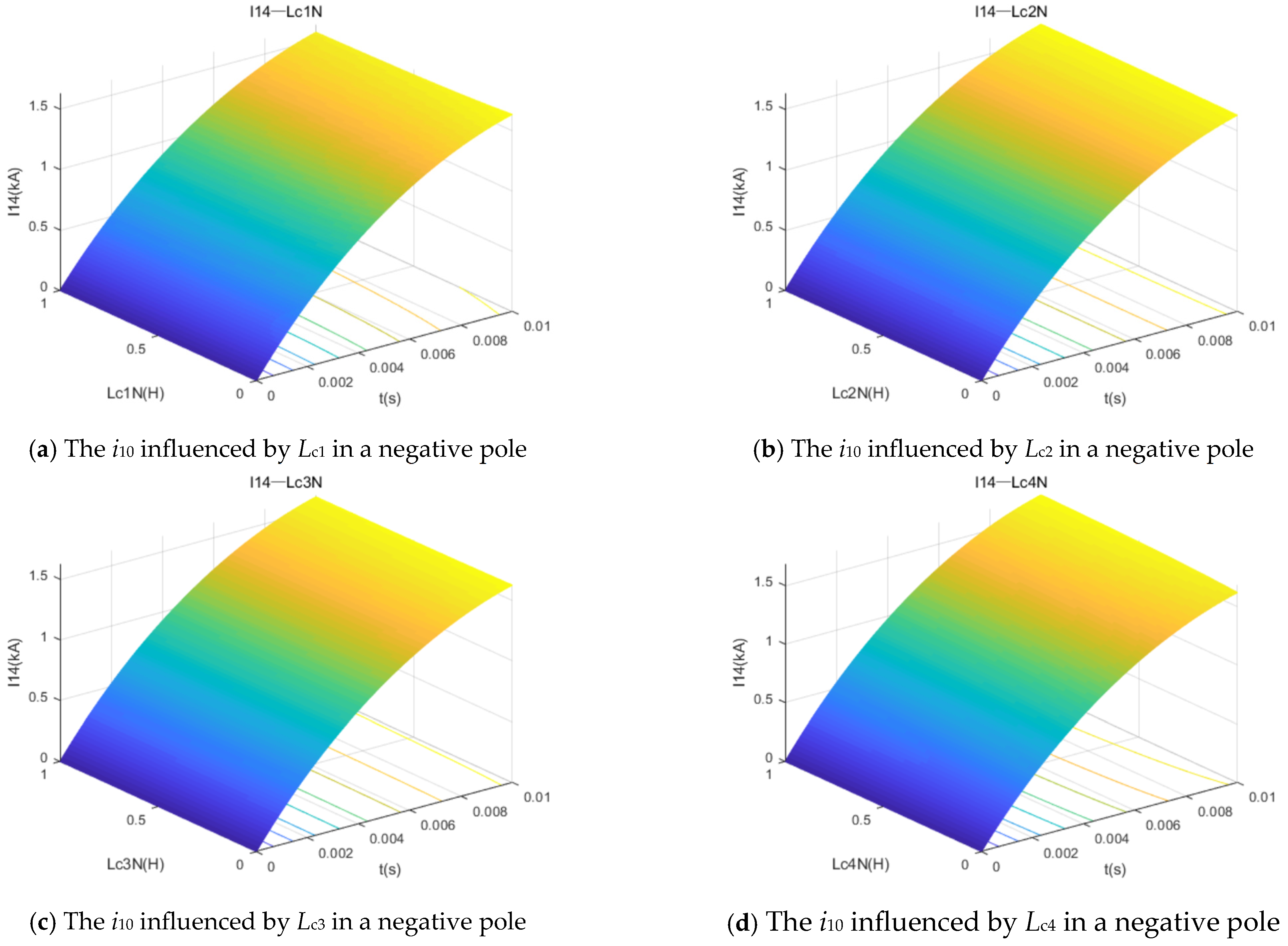
5.3. The Converter Parameters’ Impact Analysis

The influence of the arm resistance and arm inductance of each converter on the fault current i10 was analyzed. As shown in Figure 10, Figure 11 and Figure 12, due to the high value of the grounding electrode resistance, the effect of the converter’s arm resistance on the fault current can be neglected. Similarly, the sum of the grounding electrode inductance and the DC reactor inductance is much greater than the arm inductance, and the impact of the arm inductance on the fault current is primarily manifested in the value of the faulted pole’s arm inductance at the converter station directly connected to the fault line.

6. Conclusions

This paper has studied the pole-to-ground fault current calculation method and impact factor investigation for monopole DC grids.
The proposed pole-to-ground fault current calculation method is accuracy for monopole DC grids. The 4-terminal monopole DC grids calculation results prove that the calculation method is not only suitable for fault currents in fault pole, but the currents in the healthy pole are also accurate. The analysis reveals that the inductance of the faulted branch has the most significant impact on the fault current, while the inductances of the adjacent outgoing lines also exert a certain influence. However, the inductances of lines not adjacent to the faulted branch have a minimal impact on the fault current. Additionally, the grounding electrode parameters of the converter station connected to the faulted branch have the greatest influence on the fault current, with the grounding electrode parameters of neighboring converter stations also showing a notable effect. Based on the analysis of various parameters, it can be concluded that the fault current is significantly influenced by the topology of the nearby symmetrical monopole DC grid but is not affected by the fault currents at remote converter stations. Therefore, when a pole-to-ground fault occurs in this type of DC grid, it is sufficient to focus on the converter stations in the nearby area.
These findings can be helpful for large-scale hybrid ACDC grids in two aspects. The first one is that people can optimize the DC grid topology to decrease the fault current in planning stage, the second one is that the protection schemes of DC system can ignore the impact of distant converters.

Author Contributions

L.C.: Conceptualization, Writing—original draft, Writing—review and editing. W.Y.,: Software, Data curation. P.D.: Software, Data curation, Writing—review and editing. S.M.: Software, Writing—review and editing. D.K.: Software, Writing—review and editing. H.C.: Supervision, Writing—review and editing. All authors have read and agreed to the published version of the manuscript.

Funding

This work is supported by State Grid Sichuan Electric Power Company Science and Technology Project under Grant 521917230004. (Research on Active Response and Synergistic Complementarity Technology of Multi-type Distributed Generation Microgrid for Sichuan Regional Distribution Network).

Data Availability Statement

The raw data supporting the conclusions of this article will be made available by the authors on request.

Conflicts of Interest

The authors declare they are employees of State Grid Sichuan Electric Power Supply Company Meishan Branch. We declare that the research was conducted in the absence of any commercial or financial relationships that could be construed as a potential conflict of interest.

References

  1. Zhou, H.; Li, B.; Jiang, Q.; Liu, T.; Zhang, Y.; Yin, Y. The Extreme Temperature Weather Impact Mechanism Analysis of MMC-HVDC’s Harmonic Impedance and Its Dynamic Stability. Energies 2024, 17, 6044. [Google Scholar] [CrossRef]
  2. Jiang, Q.; Zeng, X.; Li, B.; Wang, S.; Liu, T.; Chen, Z.; Wang, T.; Zhang, M. Time-sharing frequency coordinated control strategy for PMSG-based wind turbine. IEEE J. Emerg. Sel. Top. Circuits Syst. 2022, 12, 268–278. [Google Scholar] [CrossRef]
  3. Verma, N.; Kumar, N.; Gupta, S.; Malik, H.; Márquez, F.P.G. Review of sub-synchronous interaction in wind integrated power systems: Classification, challenges, and mitigation techniques. Prot. Control. Mod. Power Syst. 2023, 8, 17. [Google Scholar] [CrossRef]
  4. Wang, P.; Jiang, Q.; Li, B.; Liu, T.; Li, X.; Chen, G.; Zeng, X.; Blaabjerg, F. Ultra-low frequency oscillation analysis considering thermal-hydro power proportion. Int. J. Electr. Power Energy Syst. 2023, 148, 108919. [Google Scholar] [CrossRef]
  5. Li, Q.; Li, B.; Jiang, Q.; Liu, T.; Yue, Y.; Zhang, Y. A Novel Location Method for Interline Power Flow Controllers Based on Entropy Theory. Prot. Control. Mod. Power Syst. 2024, 9, 70–81. [Google Scholar] [CrossRef]
  6. Roy, T.K.; Ghosh, S.K.; Saha, S. Robust Backstepping Global Integral Terminal Sliding Mode Controller to Enhance Dynamic Stability of Hybrid AC/DC Microgrids. Prot. Control. Mod. Power Syst. 2023, 8, 8. [Google Scholar] [CrossRef]
  7. Kok, C.L.; Tang, H.; Teo, T.H.; Koh, Y.Y. A DC-DC Converter with Switched-Capacitor Delay Deadtime Controller and Enhanced Unbalanced-Input Pair Zero-Current Detector to Boost Power Efficiency. Electronics 2024, 13, 1237. [Google Scholar] [CrossRef]
  8. Yu, J.; Li, Y.; Wan, J.; Zhou, F.; Zhang, M.; Cao, L. Tri-State Modulation with Operating Losses Minimization for a Soft-Switching Bidirectional DC-DC Converter. Prot. Control. Mod. Power Syst. 2024, 9, 58–70. [Google Scholar] [CrossRef]
  9. Jiang, Q.; Tao, Y.; Li, B.; Liu, T.; Chen, Z.; Blaabjerg, F.; Wang, P. Joint Limiting Control Strategy Based on Virtual Impedance Shaping for Suppressing DC Fault Current and Arm Current in MMC-HVDC Systems. J. Mod. Power Syst. Clean Energy 2023, 11, 2003–2014. [Google Scholar] [CrossRef]
  10. Pang, H.; Wei, X. Research on key technology and equipment for Zhangbei 500kV DC grid. In Proceedings of the 2018 International Power Electronics Conference (IPEC-Niigata 2018-ECCE Asia), Niigata, Japan, 20–24 May 2018; IEEE: Piscataway, NJ, USA, 2018. [Google Scholar]
  11. Zhang, Y.; Zhang, W.; Peng, Q.; Li, B.; Tao, Y.; Zhang, M.; Liu, T.; Blaabjerg, F. Impact of grid topology on pole-to-ground fault current in bipolar DC grids: Mechanism and evaluation. J. Mod. Power Syst. Clean Energy 2022, 11, 434–445. [Google Scholar] [CrossRef]
  12. Han, X.; Jiang, Q.; Liu, T.; Li, B.; Ding, L.; Chen, G. Research on ultra-low frequency oscillation caused by hydro power in hydro-dominant power system. In Proceedings of the 2018 International Conference on Power System Technology (POWERCON), Guangzhou, China, 6–9 November 2018; IEEE: Piscataway, NJ, USA, 2018; pp. 1909–1914. [Google Scholar]
  13. Tao, Y.; Li, B.; Liu, T.; Jiang, Q.; Blaabjerg, F. Practical Fault Current Level Evaluation and Limiting Method of Bipolar HVdc Grid Based on Topology Optimization. IEEE Syst. J. 2021, 16, 4466–4476. [Google Scholar] [CrossRef]
  14. Zhang, L.; Zou, Y.; Yu, J.; Qin, J.; Vittal, V.; Karady, G.G.; Shi, D.; Wang, Z. Modeling, control, and protection of modular multilevel converter-based multi-terminal HVDC systems: A review. CSEE J. Power Energy Syst. 2017, 3, 340–352. [Google Scholar] [CrossRef]
  15. Hou, J.; Song, G.; Fan, Y. Fault identification scheme for protection and adaptive reclosing in a hybrid multi-terminal HVDC system. Prot. Control. Mod. Power Syst. 2023, 8, 23. [Google Scholar] [CrossRef]
  16. Li, C.; Zhao, C.; Xu, J.; Ji, Y.; Zhang, F.; An, T. A Pole-to-Pole Short-Circuit Fault Current Calculation Method for DC Grids. IEEE Trans. Power Syst. 2017, 32, 4943–4953. [Google Scholar] [CrossRef]
  17. Liu, Y.; Huang, M.; Zha, X.; Iu, H.H. Short-Circuit Current Estimation of Modular Multilevel Converter Using Discrete-Time Modeling. IEEE Trans. Power Electron. 2019, 34, 40–45. [Google Scholar] [CrossRef]
  18. Adam, G.P.; Abdelsalam, I.; Fletcher, J.E.; Burt, G.M.; Holliday, D.; Finney, S.J. New Efficient Submodule for a Modular Multilevel Converter in Multiterminal HVDC Networks. IEEE Trans. Power Electron. 2017, 32, 4258–4278. [Google Scholar] [CrossRef]
  19. Etxegarai, A.; Larruskain, D.M.; Iturregi, A.; Saldaña, G.; Apiñaniz, S. Performance of a superconducting breaker for the protection of HVDC grids. IET Gener. Transm. Distrib. 2020, 14, 997–1004. [Google Scholar] [CrossRef]
  20. Yao, L.Z.; Yao, Z.Q.; Lin, Z. Research on DC Fault Characteristics of Modular Multilevel Converter-Based High-Voltage DC Transformer. Power Syst. Technol. 2016, 40, 1051–1058. [Google Scholar]
  21. Wang, S.S.; Zhou, X.Y.; Tang, G.F.; He, Z.Y.; Teng, L.T.; Bao, H.L. Analysis of Submodule Overcurrent in Modular Multilevel Converter HVDC During DC Pole-to-Pole Short Circuit. Proc. CSEE (Chin. J. Electr. Eng.) 2011, 31, 7. [Google Scholar]
  22. Wang, W.R.; He, Z.Y.; Li, G.Q.; Xin, Y.C.; Gu, G.H. Recursive Calculation Method for DC Fault Current in MMC-HVDC Considering AC Influence. Proc. CSEE (Chin. J. Electr. Eng.) 2019, 39, 313–320. [Google Scholar]
  23. Yang, H.; Dong, Y.; Li, W.; He, X. Average-value model of modular multilevel converters considering capacitor voltage ripple. IEEE Trans. Power Deliv. 2016, 32, 723–732. [Google Scholar] [CrossRef]
Figure 1. The different grounding types for a monopole DC system.
Electronics 14 01067 g001
Figure 2. The detailed and equivalent symmetrical monopole MMC model for analysis.
Electronics 14 01067 g002
Figure 3. DC grid model for pole-to-ground fault analysis.
Electronics 14 01067 g003
Figure 4. Four-terminal symmetrical monopole DC grid model.
Electronics 14 01067 g004
Figure 5. The fault current results comparison for positive converters.
Electronics 14 01067 g005
Figure 6. The fault current results comparison for negative converters.
Electronics 14 01067 g006
Figure 7. The fault currents i10 influenced by line inductances.
Electronics 14 01067 g007
Figure 8. The i10 fault currents, influenced by grounding electrode resistances.
Electronics 14 01067 g008
Figure 9. The i10 fault currents, influenced by grounding electrode inductances.
Electronics 14 01067 g009
Figure 10. The i10 fault currents, influenced by arm resistances in a positive pole in the fault.
Electronics 14 01067 g010
Figure 11. The i10 fault currents, influenced by arm inductances in a positive pole in the fault.
Electronics 14 01067 g011
Figure 12. The i10 fault currents, influenced by arm inductances in negative healthy poles.
Electronics 14 01067 g012
Table 1. The distribution of grounding resistance.
iip/i(i+m)(p+m)ipi/i(p+m)(i+m)ipj/i(p+m)(j+m)ijp/i(j+m)(p+m)ipq/i(p+m)(q+m)iqp/i(q+m)(p+m)
RiRiRjRj00
Table 2. The equivalent resistances of the converter positive poles (the corresponding negative parts are zero).
iipipiipjijpipqiqp
RciRciRcjRcj00
Table 3. The equivalent resistances of the converter negative poles (the corresponding positive parts are zero).
i(i+m)(p+m)i(p+m)(i+m)i(p+m)(j+m)i(j+m)(p+m)i(p+m)(q+m)i(q+m)(p+m)
RciRciRcjRcj00
Table 4. The converter parameters in the 4-terminal DC grid.
Converter No.Converter Control ModesConverter Parameters
L0 (mH)R0 (Ω)C0 (μF)NSM
1P = 750 MW
Q = 0 Mvar
1000.27227500200
2P = 1500 MW
Q = 0 Mvar
500.181615,000200
3P = −1500 MW
Q = 0 Mvar
500.181615,000200
4Udc = 500 kV1001.0897500200
Q = 0 Mvar
Table 5. The system parameters in 4-terminal DC grid.
Line No.Length
(km)
Resistance
(Ω/km)
Inductance
(mH/km)
Smooth Conductor Inductance (mH)
L121000.01980.82150
L143000.01980.82150
L234000.01980.82150
L342000.01980.82150
Disclaimer/Publisher’s Note: The statements, opinions and data contained in all publications are solely those of the individual author(s) and contributor(s) and not of MDPI and/or the editor(s). MDPI and/or the editor(s) disclaim responsibility for any injury to people or property resulting from any ideas, methods, instructions or products referred to in the content.

