Abstract
This paper proposes a multi-channel robust damping controller based on the static H∞ loop shaping method, specifically tailored for modular multilevel converter-based high-voltage direct current (MMC-HVDC) systems with embedded energy storage. The controller is designed to suppress sub-synchronous oscillations, a critical issue in power systems. To optimize the controller’s performance, a genetic algorithm is employed to tune the weighting functions for robust control. Additionally, the TLS-ESPRIT (Total Least Squares–Estimation of Signal Parameters via Rotational Invariance Techniques) identification algorithm is utilized to clarify the system oscillation characteristics, thereby enhancing the controller’s effectiveness. Simulation results demonstrate that the sub-synchronous oscillation controller, designed based on the proposed robust control algorithm, achieves satisfactory oscillation suppression effects under various disturbances, underscoring its robustness. This study highlights the potential of MMC-HVDC systems with embedded energy storage in mitigating power grid oscillations, contributing to the advancement of power system stability and reliability.
1. Introduction
In power systems, two prevalent instability modes are oscillatory and monotonic instability [1,2]. Sub-synchronous oscillation (SSO) represents a distinct type of oscillatory instability, emerging from the intricate coupling between the dynamic behaviors of different electrical components within the system, such as the interaction of a series-compensated line and the converter [3]. This coupling gives rise to a specialized dynamic response, characterized by sustained or intensifying oscillations in key variables of both mechanical and electrical subsystems.
Continuous oscillations in the electrical grid destabilize the entire system, while analogous disturbances in mechanical components inflict cumulative damage on the shafting of steam turbine–generator units, accelerating component degradation and reducing service life [4,5]. When SSO escalates to critical levels or induces excessive torsional vibrations, it can catastrophically compromise the integrity of large-scale turbine–generator rotor shafts. Such failures risk triggering widespread power outages, system-wide blackouts, or cascading failures that threaten the reliability and security of the entire power infrastructure.
The escalating annual deployment of renewable energy sources, with wind power at the forefront, is driving large-scale integration into thermal-dominated power grids. This paradigm shift introduces unprecedented challenges for sub-synchronous oscillation (SSO) analysis. High-voltage direct current (HVDC) transmission networks pose a critical risk by inducing sub-synchronous torsional vibrations (SSTVs) in steam turbine–generator units, which can precipitate progressive shaft fatigue or catastrophic failures that destabilize grid operations [6].
The proliferation of utility-scale wind farms, particularly when deployed under wind–thermal bundled transmission configurations, has created a tightly coupled energy ecosystem. This interdependence amplifies the potential for SSTV propagation across wind farms, thermal generators, and HVDC corridors [7]. A stark illustration of this vulnerability occurred in July 2015, when direct-drive wind turbine clusters in Xinjiang’s Hami region triggered recurrent SSO events. The oscillatory power traversed multi-tier grid architectures, exciting torsional resonance in a steam turbine shaft 300 km away. This led to a plant-wide generator trip and a 60% reduction in Utral HVDC (UHVDC) transmission capacity via the Tianzhong corridor, causing a major grid disturbance.
To safeguard conventional thermal units in weak sending-end systems operating under wind–thermal bundling and to avert economically crippling outages, proactive enhancement of SSO mitigation strategies within wind–thermal bundled DC transmission frameworks is now critical. This requires interdisciplinary collaboration to develop adaptive control architectures, real-time monitoring systems, and resilient grid planning protocols that preemptively address SSO propagation pathways.
Addressing sub-synchronous oscillation (SSO) challenges associated with HVDC-transmitted thermal power generation necessitates innovative control engineering solutions. Modern optimization techniques, including genetic algorithms (GAs), particle swarm optimization (PSO), and fuzzy immune algorithms (FIAs) [8], are increasingly utilized to design supplementary sub-synchronous damping controllers (SSDCs). While these approaches effectively suppress SSO, their reliance on high-fidelity system models and precise parameter estimation poses implementation barriers. Accurate power system modeling remains a formidable task, constraining controller adaptability and often resulting in prohibitively complex controller architectures unsuitable for large-scale deployment [9].
Recent investigations explore alternative damping augmentation strategies using diverse feedback signals. For example, reference [10] proposed line current feedback for dominant torsional mode suppression, though these risks destabilize low-frequency dynamics. By contrast, reference [11] demonstrated enhanced stability across dominant and non-dominant modes by leveraging generator speed feedback. Meanwhile, reference [12] capitalized on the decoupled active/reactive power regulation capabilities of doubly fed induction generator (DFIG)-based wind farms, showing through eigenvalue and time-domain analyses that supplementary controls can bolster system damping. Despite these insights, the underlying mechanisms governing DFIG-induced damping—including damping topology, electromagnetic–mechanical coupling pathways, and quantitative electrical damping coefficients—remain underexplored.
Reference [13] corroborated the potential of DFIG-based active/reactive power loop damping strategies via simulation yet failed to establish design foundations or quantify achievable positive damping margins. These studies also neglect operational constraints inherent to wind farm power regulation. Similarly, reference [14] adopted a single-mode torsional vibration focus during controller synthesis, necessitating high-precision torsional vibration monitoring while offering no guarantees of positive damping contributions across all modes.
This research gap underscores the need for holistic control frameworks that integrate multi-modal torsional dynamics, operational constraints, and adaptive parameter tuning. Future work should prioritize physics-informed modeling of DFIG–grid interactions, hybrid optimization algorithms balancing computational efficiency and control fidelity, and experimental validation of damping enhancement strategies under realistic grid conditions.
Recent advancements have introduced battery energy storage system-integrated modular multilevel converters (BESS-MMCs) as a transformative solution for AC voltage support, with emerging research underscoring their transformative potential. By strategically embedding energy storage units (ESUs) within the sub-modules of modular multilevel converters (MMCs), BESS-MMCs exploit structural synergies to unlock enhanced dynamic control capabilities for VSC-HVDC transmission.
Contemporary investigations into BESS-MMCs center on three core domains: (1) topological optimization to maximize energy density and power conversion efficiency [15]; (2) state-of-charge (SOC) coordination strategies ensuring balanced energy distribution across sub-modules under transient conditions [16]; and (3) fault ride-through (FRT) augmentation techniques that sustain grid stability during disturbances [17]. These studies reveal critical advantages—including plug-and-play scalability, inherent redundancy against component failures, and decentralized control compatibility—that position BESS-MMCs as a viable technology for sub-synchronous oscillation (SSO) suppression.
The modular architecture of BESS-MMCs enables localized, real-time power injection/absorption to counteract SSO-induced torsional interactions, while their fault-tolerant design mitigates single-point-of-failure risks. Furthermore, their compatibility with hierarchical control frameworks allows seamless integration into existing grid protection schemes. Future research should prioritize hardware-in-the-loop validation of BESS-MMC-based SSO mitigation strategies, exploring synergies with wide-area damping controllers and hybrid energy storage systems to optimize system resilience under diverse operating scenarios.
To mitigate the persistent challenge of sub-synchronous oscillations (SSOs) destabilizing power systems, this study introduces a supplementary damping controller (SDC) architecture integrated with a next-generation battery energy storage system–modular multilevel converter (BESS-MMC). By embedding the SDC within the BESS-MMC’s outer active power control loop, this innovation expands the converter’s dynamic control envelope, enabling real-time power modulation to counteract SSO-induced torsional interactions. The contributions of this paper are as follows:
- (1)
- The proposed Synchronized Damping Controller (SDC) is specifically tailored for the battery energy storage system-modular multilevel converter (BESS-MMC) topology. By capitalizing on the inherent structural merits of the BESS-MMC, the SDC enables dual-mode operation, encompassing energy storage management and active damping injection, through a unified control interface. This innovative integration obviates the requirement for auxiliary hardware, while maintaining the plug-and-play scalability of the BESS-MMC system.
- (2)
- Leveraging advanced H∞ control techniques, the SDC demonstrates robustness against grid impedance variations, the intermittency of renewable energy sources, and parameter uncertainties induced by faults. Consequently, it ensures stable performance across a wide range of operating conditions, spanning from nominal load scenarios to post-disturbance recovery phases.
- (3)
- The SDC adopts a parallelized multi-channel architecture equipped with adaptive notch filters. These filters are specifically designed to target both sub-synchronous oscillations (SSOs) within the frequency range of 10–50 Hz and low-frequency inter-area oscillations in the 0.1–2 Hz range. Each channel incorporates frequency-adaptive phase compensation, which aligns damping injections with the dynamics of oscillatory modes. This enables the simultaneous suppression of multiple instability mechanisms without any cross-channel interference.
2. The Structure and Control of MMC-HVDC with Embedded Energy Storage
2.1. Control Structure of MMC-HVDC
The control strategy for modular multilevel converter-based high-voltage direct current (MMC-HVDC) grids is the linchpin for secure and stable operation, spanning the entire lifecycle of DC grid development—from conceptual planning and engineering design to real-time operational management. A well-architected control system is foundational to ensuring MMC-HVDC reliability, enabling adaptive responses to dynamic grid conditions while maintaining strict voltage/current tracking accuracy.
As depicted in Figure 1, MMC-HVDC systems adopt a tri-layered hierarchical control paradigm with distinct functional roles at each tier:
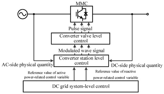
Figure 1.
Schematic diagram of hierarchical control for MMC-HVDC.
- (1)
- The system-level control (top tier) coordinates grid-wide objectives, including power flow optimization, frequency regulation, and AC/DC network stability. This layer interfaces with system operators to enforce economic dispatch strategies and real-time contingency management. This layer operates with ms-level latency.
- (2)
- The converter station-level control (intermediate tier) manages station-specific functions such as reactive power support, AC voltage regulation, and DC link voltage stabilization. It integrates predictive algorithms with real-time monitoring to mitigate disturbances (e.g., fault ride-through, renewable intermittency). This layer also operates with ms-level latency.
- (3)
- The converter valve-level control (bottom tier) executes precise pulse-width modulation (PWM) commands to individual semiconductor valves, ensuring sub-millisecond transient response and harmonic distortion suppression. This layer operates with μs-level latency to enforce high-fidelity current/voltage tracking.
This decentralized yet coordinated architecture balances computational efficiency with adaptive control granularity. The top-down flow of reference signals (e.g., active/reactive power setpoints) and bottom-up feedback (e.g., valve thermal stress metrics) creates a closed-loop stability framework resilient to parameter uncertainties and topological changes. Future research should explore hybrid control strategies integrating machine learning for predictive fault isolation and adaptive parameter tuning across these hierarchical layers.
The system-level control (SLC) framework in voltage source converter-based high-voltage direct current (VSC-HVDC) grids serves a dual mandate: power flow optimization and DC voltage stability maintenance. By dynamically dispatching active control variables (e.g., active power setpoints, DC voltage references, AC frequency regulation targets) and reactive control variables (e.g., reactive power support, AC voltage stabilization commands) from the central control center, the SLC establishes hierarchical command references for each converter station. These references are fed into station-level controllers (SLCs), which execute advanced control paradigms—including indirect current control (ICC), direct current control (DCC), and power synchronization control (PSC)—to synthesize modulation waveforms, where these control also operate with ms-level latency. While DCC remains the industry standard due to its superior transient response, hybrid control approaches integrating machine learning for predictive parameter adaptation are emerging.
The synthesized modulation waveforms are then transmitted to valve-level controllers (VLCs), which employ nearest level modulation (NLM) to determine the optimal sub-module (SM) activation count per converter arm for the next control interval. NLM leverages real-time capacitor voltage balancing (CVB) algorithms to minimize voltage deviations across SM capacitors using predictive sorting-based pulse distribution, enhance fault tolerance by prioritizing SMs with higher state-of-charge (SOC) during transient events, and optimize switching losses through dynamic pulse-width modulation (PWM) frequency scaling.
The VLCs ultimately distribute triggered pulses to the selected SMs, ensuring precise power conversion while maintaining DC link stability. This hierarchical control loop—spanning system-level dispatch, station-level modulation synthesis, and valve-level pulse distribution—enables VSC-HVDC grids to achieve sub-millisecond fault clearance and adaptive power flow regulation under diverse operating conditions.
2.2. Converter Station-Level Control Strategy
The station-level control of voltage source converters (VSCs) in high-voltage direct current (HVDC) systems primarily employs two methodologies: indirect current control (ICC) and direct current control (DCC). ICC determines the amplitude and phase of the converter’s AC output voltage through predefined control objectives, transmitting these references to the valve-level controller (VLC) to generate triggering pulses for sub-module (SM) switching. While ICC offers simplified control architecture, its performance is significantly constrained by AC system impedance variations, resulting in sluggish AC current dynamics and vulnerability to valve over currents during transient events.
In contrast, DCC adopts a hierarchical dual-loop structure integrating an outer voltage regulation loop (e.g., DC voltage or reactive power control) and an inner current tracking loop (e.g., dq-axis current control with feedforward decoupling). This configuration enables μs-level current response times and inherent overcurrent mitigation via current limiters, making DCC the dominant choice for high-voltage, large-capacity VSC-HVDC applications. The subsequent analysis focuses on dq-decoupled DCC principles, emphasizing their superior adaptability to hybrid AC/DC grid topologies.
Figure 2 depicts the circuit topology of a three-phase HB-MMC, a cornerstone of modern VSC-HVDC systems. Key parameters include the following:
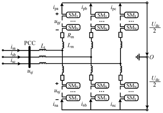
Figure 2.
The circuit structure of MMC.
AC-side variables: isj and usj (j = a,b,c) denote the three-phase currents and voltages at the point of common coupling (PCC).
Arm currents: ipj and inj represent the currents flowing through the upper (p) and lower (n) arms of phase j, respectively.
Arm voltages: upj and unj correspond to the instantaneous voltages across the upper and lower arms.
DC-link parameters: Udc is the DC voltage, while Lt, Rm, and Lm denote the leakage inductance of the coupling transformer, the arm resistance, and the arm inductance, respectively.
This configuration facilitates modular scalability and fault ride-through capability via independent arm control, which is pivotal for integrating renewable energy sources into HVDC grids.
By applying Kirchhoff’s Voltage Law (KVL) to the upper (p) and lower (n) arms of a modular multilevel converter (MMC) phase leg, the following voltage balance equations can be formulated:
We also define the following:
By summing Equations (1) and (2), the following relationship can be derived:
In Equation (5), ucj represents the equivalent virtual equipotential voltage across the upper and lower converter arms. By dynamically regulating ucj, stable AC output voltage usj and current isj can be achieved. When Equation (5) is expanded into its three-phase form, the resulting dynamic equations governing the AC-side behavior of the modular multilevel converter (MMC) in the abc stationary reference frame are derived as follows:
To obtain control-friendly variables, the Park transformation is applied to Equation (6), yielding its mathematical representation in the d-q synchronous rotating reference frame as follows:
According to the instantaneous power theory, the AC instantaneous power in the d-q synchronous rotating reference frame can be expressed as follows:
In a phase-locked loop (PLL) system, the voltage vector Us at the point of common coupling (PCC) is typically aligned with the d-axis of the synchronous reference frame. Consequently, under steady-state operating conditions, the following relationships hold: usd = Us (d-axis component equals the voltage magnitude) and usq = 0 (q-axis component is zero). Under these assumptions, Equation (8) simplifies to
From Equation (9), it is evident that the active power (P) and reactive power (Q) can be independently regulated by adjusting the d-axis (isd) and q-axis (isq) components of the AC current, respectively, thereby achieving decoupled control of active and reactive power. The regulation of isd and isq is implemented through outer-loop voltage control, which employs proportional–integral (PI) controllers to eliminate steady-state errors in the input variables. The control architecture is illustrated in Figure 3a.
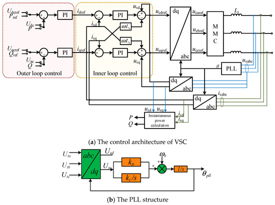
Figure 3.
Structure diagram of MMC-HVDC control.
Although in practice it is not evident that P and Q will be independently controlled, we select the independent control of P and Q in this paper. As the PLL is the key component contributing to instability, the information related to the PLL should not be neglected. Figure 3b shows the control diagram of the classical PLL used in most VSC-HVDCs. , , and are the three phase voltages of , and and are the q-axis and d-axis voltages of , respectively. and are the PI parameters and generator angular frequency , in which is the fundamental frequency. The output represents the phase angle of .
Based on control requirements, the input variables for the d-axis (active power-related) control loop include active power (P) and DC voltage (Udc), while the q-axis (reactive power-related) control loop primarily uses reactive power (Q) and AC voltage (Us) as inputs. The deviations between the outer-loop input variables and their reference values are processed through proportional–integral (PI) controllers to generate the inner-loop current references idref and iqref. The inner-loop current controller in a VSC HVDC system is responsible for regulating the converter’s output current to follow a reference value. However, the output current is influenced by both the control action and the grid voltage. Voltage feed-forward control allows the controller to anticipate and compensate for grid voltage disturbances before they affect the current, thereby improving the system’s dynamic response. The inner-loop current control employs current feedback and grid voltage feedforward compensation to produce the d-axis and q-axis references for the fundamental virtual equipotential voltage (ucdref and ucqref). These references are then transformed via the inverse Park transformation into three-phase modulation waves (ucjref). Finally, according to the nearest level modulation (NLM) strategy, the number of sub-modules (SMs) to be inserted into the upper and lower converter arms is determined as follows:
In the above expressions, NSM denotes the total number of sub-modules (SMs) in each converter arm, and Uc represents the average capacitor voltage across these sub-modules. By systematically activating and deactivating the sub-modules within each arm of the modular multilevel converter (MMC), station-level control of the converter is achieved.
2.3. The MMC-HVDC with Embedded Energy Storage
The topology of the modular multilevel converter–battery energy storage system (MMC-BESS) is depicted in Figure 4. Each sub-module (SM) integrates a decentralized energy storage port by incorporating a non-isolated DC/DC converter connected to a battery, diverging from the conventional MMC structure. This design enables independent bidirectional control of battery charging and discharging via a dual-mode Buck/Boost energy storage converter, granting each sub-module the capability to absorb or compensate active power dynamically. By treating the energy storage port as a third terminal, the MMC-BESS adopts a three-port architecture, facilitating bidirectional energy transfer between any two ports.
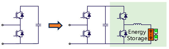
Figure 4.
The sub-module with embedded energy storage.
Here, the inductance represents the battery filter inductor, which suppresses harmonic currents to safeguard the battery from degradation. The non-isolated DC/DC converter provides bidirectional power flow between the battery and the sub-module capacitor, operating as either a Buck (step-down) or Boost (step-up) converter:
Buck mode (battery charging): When the upper switch is turned ON and the lower switch is turned OFF, the DC/DC converter functions as a Buck converter. Current flows from the sub-module capacitor to the battery, charging the battery. In this state, the half-bridge sub-module can be modeled as an equivalent resistor.
Boost mode (battery discharging): When the same switching configuration is used with complementary duty-cycle modulation or phase-shifted control, the DC/DC converter operates as a Boost converter. Current flows from the battery to the sub-module capacitor, discharging the battery. By dynamically regulating the DC/DC converter, the battery’s energy capacity is optimized, enabling bidirectional energy exchange (absorption or delivery) tailored to the system’s power demands.
3. Design of Multi-Channel Robust Damping Controllers Based on the Static H∞ Loop Shaping Method
3.1. H∞ Loop Shaping Method
H∞ loop shaping is an approach that employs the H∞ method to design controllers, enabling the system to achieve favorable stability and robustness. The process of designing a controller using this method mainly involves three steps:
Loop shaping: Pre-compensator W1(s) and post-compensator W2(s) are utilized to perform loop shaping on the system’s plant G(s). The shaped plant is then represented as Gp(s) = W2(s)G(s)W1(s).
Robust stabilization: calculate the maximum robust stability margin ε_max according to the following equations:
The stabilizing controller K∞(s) is derived, which is capable of stabilizing a set of uncertain disturbance models of the plant . Here, , represents the uncertainty associated with the controlled model G(s), where and . Additionally, the state-space realizations of N and M are given as follows:
where , , whereas Z is the solution to the following Riccati equation:
where .
The structured multiplicative (or normalized coprime factor) uncertain disturbance model is illustrated in Figure 5, as depicted below:
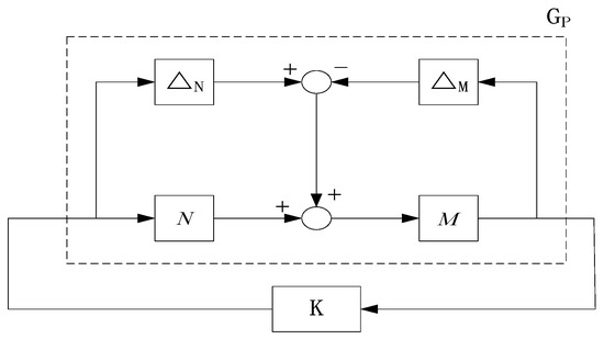
Figure 5.
Normalized coprime factor uncertainty decomposition.
Controller synthesis: By leveraging the previously derived H∞-based robust stabilizing controller K∞(s) and the pre-selected weighting functions W1(s) and W2(s), the final output-feedback controller K(s) is obtained as follows:
The loop shaping procedure is illustrated in Figure 6.
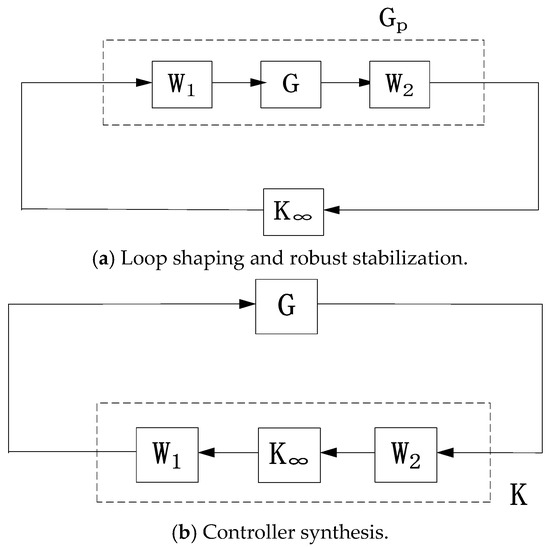
Figure 6.
Loop shaping procedure.
The H∞-based loop shaping approach, termed the “central controller” method by McFarlane and Glover, is characterized by its conceptually straightforward principle and computationally efficient implementation. However, the robust controllers designed via this method typically exhibit high orders, which often remain significant even after applying model reduction techniques.
3.2. Static Loop Shaping Method
Figure 7 depicts the block diagram of a system with loop shaping using normalized coprime factors. In this diagram, W1 and W2 represent external disturbances, while z1 and z2 denote the evaluation (or performance) outputs.
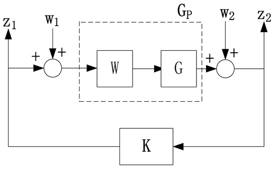
Figure 7.
The block diagram for loop shaping using normalized coprime factors.
The static H∞ loop shaping method minimizes the infinity norm (or H∞-norm) of a transfer function matrix via linear matrix inequalities (LMIs) to solve for a robust stabilizing controller K, thereby ensuring the accuracy and superiority of the designed controller. Compared with the earlier McFarlane’s central controller method, this approach yields controllers with a lower order, matching the order of the weighting functions used.
Given the loop-shaped state-space realization of the system G as , if a static H∞-robust stabilizing controller K exists, it must satisfy Equation (11). The controller K can be solved via the linear matrix inequality (LMI) formulation specified in Equation (15):
Here, , and P = γR, where nu and ny denote the number of system inputs and number of system outputs, respectively. The unknown parameters γ and matrix R in Equation (15) can be determined by solving for the variable β and matrix P through the following system of linear matrix inequalities (LMIs), specifically Equations (18) and (19).
In Equations (18) and (19), the matrix Z is the unique stabilizing symmetric positive-definite solution of the Riccati equation. If a solution exists for Equations (18) and (19), it guarantees the existence of a static H∞-robust stabilizing controller K satisfying Equation (14). The final designed static H∞-loop-shaped robust controller is then given by Kst = W2KW1. If no solution exists, the weighting functions must be readjusted. The maximum robust stability margin εmax is provided by Equation (21).
In summary, the design steps for a static H∞-loop-shaped robust controller are as follows:
- (1)
- Weighting function selection and loop shaping: select the weighting functions W1 and W2 based on practical performance specifications to perform loop shaping on the original system.
- (2)
- Feasibility analysis and optimization via LMIs: analyze the feasibility of Equations (18) and (19) using linear matrix inequalities (LMIs) and minimize the scalar variable β.
- (3)
- Controller synthesis via LMI-based solutions: Solve for the scalar γ and matrix R using the derived β and matrix P. Then, verify the feasibility of Equation (15) via LMIs to synthesize the static H∞-robust stabilizing controller K.
- (4)
- Final controller construction: Based on the loop-shaping principle, the final designed static H∞-loop-shaped robust controller is constructed as Kst = W2KW1.
The order of the final controller matches that of the weighting functions, ensuring structural compatibility.
3.3. Tuning of Weighting Functions Based on an Improved Genetic Algorithm
To tuning of weighting functions, the genetic algorithm can be used. It should be pointed out that the genetic algorithm is not the only suitable algorithm for parameter tuning. Another algorithm such as PSO can also be used for this purpose.
The specific tuning process of the improved genetic algorithm is as follows:
- (1)
- Generate an initial population:
The initial population is randomly generated. Individuals are encoded using floating-point representation, and the length of the chromosome corresponds to the number of parameters to be determined for the weighting function.
- (2)
- Define the fitness function:
Determining an appropriate fitness function is a crucial step in the overall optimization process of the genetic algorithm (GA). The error functional evaluation metric in the control system, specifically the Integral of Time multiplied by the Absolute Error (ITAE) criterion, is selected as the control objective. Meanwhile, considering the possible inherent saturation characteristics of the controlled object, a weighted factor is introduced to account for the limitation of the control variable. A multi-objective evaluation metric that comprehensively considers both the limitation of control energy and the error functional is thus established.
- (3)
- Genetic operations:
- (a)
- Selection: calculate the fitness values of each individual in the population, and select elite parent individuals based on their ranking from best to worst.
- (b)
- Crossover and mutation: The crossover operator and mutation operator can maintain the diversity of the population, endowing the algorithm with an active random search capability. To prevent the genetic algorithm (GA) from getting trapped in local optima, an adaptive crossover and mutation approach is adopted.
In traditional genetic algorithms, the crossover probability is typically set to a relatively high value, while the mutation probability is conversely set to a low value, and both remain unchanged throughout the entire optimization process. In practice, as the number of evolutionary generations increases, individuals tend to become more homogeneous, and continuing to use an excessively high crossover probability to generate new individuals becomes highly inefficient. Meanwhile, a small mutation probability fails to enable the population to effectively escape from hyperplanes, making it prone to getting trapped in local optima. Therefore, the crossover and mutation probabilities used in genetic operations are adaptively adjusted according to Equations (9)–(21).
In the formula, fmax represents the maximum fitness value within the population, favg denotes the average fitness value of each generation’s population, and f is the fitness value of the individual that is about to undergo crossover or mutation. The values of k1 and k2 are selected from the interval (0, 1). If different values of k1 and k2 are chosen according to specific requirements to calculate Pc (crossover probability) and Pm (mutation probability), then Pc and Pm can be adaptively adjusted. In this paper, when calculating Pc, k1 = 0.7 and k2 = 0.9 are taken.
After adaptively adjusting the crossover probability and mutation probability, it can be achieved that when the fitness values of individuals in the population tend to be consistent or the algorithm gets trapped in local optima, the probabilities increase; conversely, they decrease. Meanwhile, individuals with fitness values higher than the average are assigned smaller crossover and mutation probabilities to protect and prioritize them for entering the next generation; individuals with fitness values lower than the average are assigned larger crossover and mutation probabilities to accelerate their elimination.
4. Simulation Verifications
Taking the ±500 kV DC project as the test system for this project, and based on the DC topology, a wind–thermal bundled power transmission system model via the MMC-BESS (modular multilevel converter with battery energy storage system) is constructed by integrating a wind power base near the thermal power plant at the sending end, as illustrated in Figure 8, to verify the effectiveness of the controller proposed in this project.
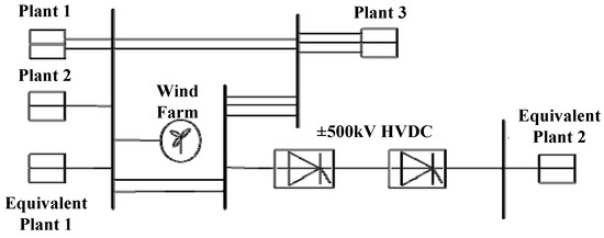
Figure 8.
The simulation system.
This model is based on the practical regional grid in the Chinese southern power grid, where Plant 1, Plant 2, Plant 3, and Equivalent Plant 1 are the sending end system of the HVDC project, while the Equivalent Plant 2 is the receiving end system. In addition, Equivalent Plant 1 and 2 are both AC equivalent grids with SCR ratios. The main parameters of the system can be found below Table 1.

Table 1.
The parameters of the model.
When establishing the electromagnetic transient model of the test system, 500 kV lines are primarily considered, with appropriate equivalent processing of 220 kV lines and loads. The wind farm, consisting of 360 equivalent aggregated doubly fed induction generators (DFIGs), is connected to Substation 1 with a rated capacity of 500 MW. Its aggregated model is obtained by paralleling an ideal controlled current source with a detailed model of a single DFIG. There are a total of five identical steam turbine generator units at the sending end, all represented by a four-mass block model. The rotor shaft system of each unit mainly comprises four shaft sections, the high-intermediate pressure combined cylinder (HIP), low-pressure cylinder A (LPA), low-pressure cylinder B (LPB), and the generator (GEN), where the following assumptions and simplifications should be stated: (1) The shaft system is discretized into a finite number of lumped masses, each representing a segment of the shaft. (2) Each mass is treated as a rigid body during torsional vibrations, ignoring internal deformations, which simplifies the dynamic equations by avoiding consideration of internal stress distributions within the masses. (3) Only torsional vibrations of the shaft are considered, and bending vibrations are neglected for simplification. (4) The damping of the shaft is modeled as linear viscous damping, proportional to velocity. (5) The moment of inertia of each mass remains constant during vibrations.
The unit participation factor method is utilized to determine the units in the power plant that are most prone to sub-synchronous oscillation. Consequently, a 0.01 per-unit (p.u.) step disturbance is applied at the constant current control point on the DC rectifier side. The difference in rotor angular velocity of Unit 1 in the power plant, with and without the small disturbance, is taken as the output. The TLS-ESPRIT (Total Least Squares–Estimation of Signal Parameters via Rotational Invariance Techniques) algorithm is then employed to identify the oscillation characteristics of the test system. The TLS-ESPRIT algorithm offers several advantages for SSO identification: it does not rely on complex spectral peak searches, thus reducing computational complexity and storage requirements. By leveraging the rotational invariance property of the signal subspace, TLS-ESPRIT decomposes the array or system data into two overlapping subarrays, constructs a covariance matrix, and then applies eigenvalue decomposition to estimate the signal parameters. This approach enables accurate identification of oscillation frequencies, damping ratios, and mode shapes associated with SSO. In the context of SSO, TLS-ESPRIT can process measurement data from phasor measurement units (PMUs) or other monitoring devices to extract modal information of the power system, facilitating the detection and analysis of sub-synchronous resonant modes.
The identification results are presented in Table 2. From the identification results, it can be observed that the system exhibits two oscillation modes in the sub-synchronous frequency bands.
Table 2.
Oscillation characteristics of the test system.
4.1. Case 1
At the moment of 2 s, the current setpoint of the constant current controller at the DC rectifier side undergoes a step change from 1 pu to 1.02 pu, and then it changes from 1.02 pu to 1.04 pu at 5 s. The suppression effects on various oscillation modes of the rotor angular velocity difference for Unit 1 in Power Plant 1 and other signals are illustrated in Figure 9, Figure 10, Figure 11, Figure 12 and Figure 13.
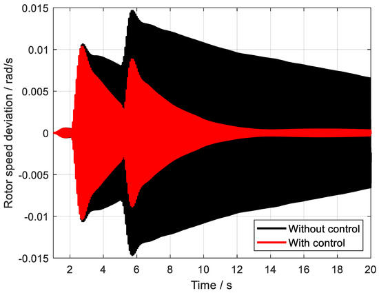
Figure 9.
The control effect of SSO1.
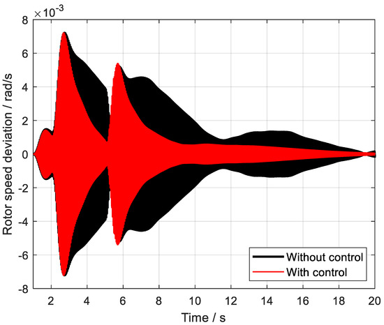
Figure 10.
The control effect of SSO2.
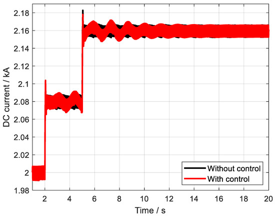
Figure 11.
The DC currents of HVDC with and without control.
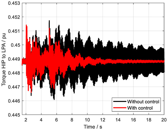
Figure 12.
The torque HIP to LPA with and without control.
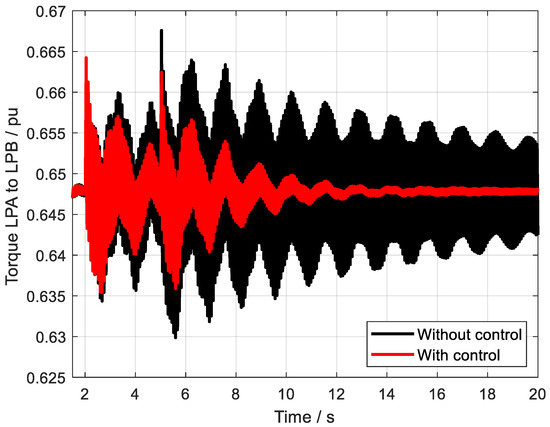
Figure 13.
The torque HIP to LPA with and without control.
As can be clearly observed from the detailed analyses presented in Figure 9 and Figure 10, the multi-channel robust damping controller, which has been meticulously designed utilizing the static H∞ loop shaping method, exhibits remarkable capabilities in swiftly and accurately suppressing the sub-synchronous oscillation phenomena that may occur within the system. This controller demonstrates an outstanding level of control performance, effectively mitigating the adverse effects of sub-synchronous oscillations, which are known to potentially compromise the stability and reliability of power systems. By employing the static H∞ loop shaping approach, the controller is able to achieve a robust and adaptive response to varying system conditions, ensuring consistent and reliable damping of sub-synchronous oscillations across a wide range of operating scenarios. Overall, the performance of this multi-channel robust damping controller underscores its effectiveness and potential for widespread application in power systems where sub-synchronous oscillation suppression is of critical importance.
4.2. Case 2
At precisely the 3 s mark during system operation, a severe three-phase ground short-circuit fault, lasting for 0.17 s, suddenly occurs on the 220 kV side of Unit 1 within Power Plant 3. This fault introduces significant disturbances into the power system, potentially triggering various oscillation modes that could destabilize the system.
To assess the impact of this fault and the effectiveness of the control measures in place, we focus on the suppression effects on different oscillation modes, particularly the rotor angular velocity difference for Unit 1 in Power Plant 1, along with other relevant signals. These suppression effects are vividly illustrated in the subsequent Figure 14, Figure 15, Figure 16, Figure 17 and Figure 18 and Table 3.
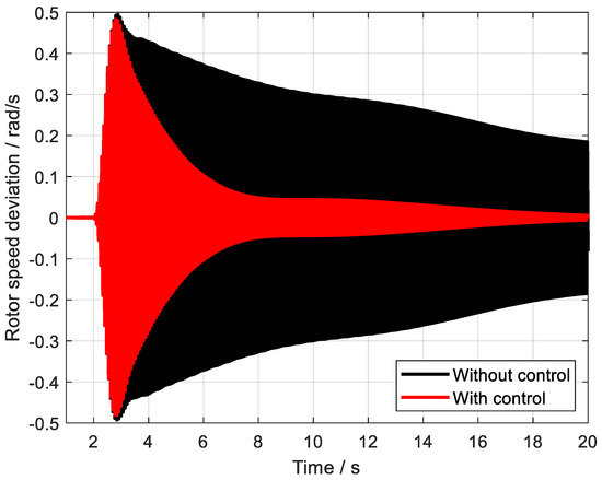
Figure 14.
The control effect of SSO1.
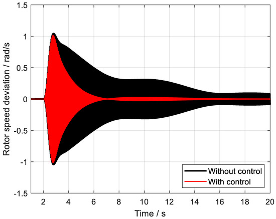
Figure 15.
The control effect of SSO2.
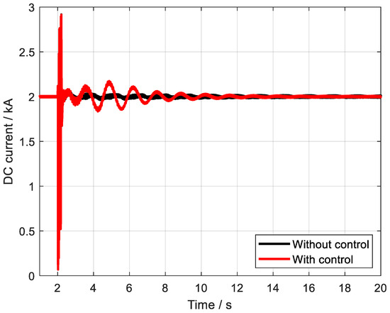
Figure 16.
The DC currents of HVDC with and without control.
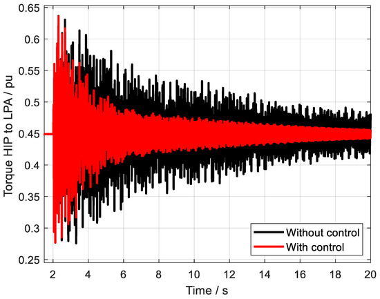
Figure 17.
The torque HIP to LPA with and without control.
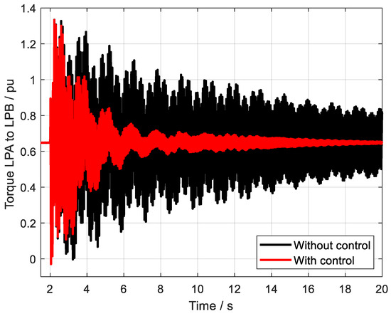
Figure 18.
The torque LPA to LPB with and without control.
Table 3.
Damping ratio before and after control.
Upon careful examination of these figures, it becomes evident that, despite the challenging fault conditions, the designed controller continues to exhibit a highly satisfactory oscillation suppression effect. It successfully dampens the oscillations that would otherwise propagate through the system, thereby maintaining the stability and reliability of the power grid. This outstanding performance underscores the controller’s robustness, demonstrating its ability to withstand and mitigate the effects of severe faults, ensuring the smooth and uninterrupted operation of the power system.
It should be noted that Figure 16 presents the output of the controllers, where the controllers are the DC system and the output is the DC currents. Thus, when the control strategy is added to the DC system, the controller outputs more power to decrease the oscillations. But if no control strategy is added to the DC system, no output will be generated, thus the DC current is a line without oscillations.
5. Conclusions
Through theoretical analysis and simulation verification, the research conclusions drawn in this paper are as follows:
- (1)
- A multi-channel robust damping controller based on the static H∞ loop shaping method has been proposed, achieving the suppression of sub-synchronous oscillation, which is based on the MMC-HVDC with embedded energy storage.
- (2)
- The weighting functions for robust control have been tuned using a genetic algorithm, and the system oscillation characteristics have been clarified through the TLS-ESPRIT identification algorithm, thereby enhancing the effectiveness of the controller.
- (3)
- The sub-synchronous oscillation controller designed based on the proposed robust control algorithm can achieve satisfactory oscillation suppression effects under different disturbances, demonstrating the robustness of the designed controller. It shows that the MMC-HVDC with embedded energy storage has the ability to suppress the power grid oscillations.
Author Contributions
Investigation, J.Z.; methodology, G.Z.; validation, J.Z. and Y.J.; writing—original draft preparation, J.Z.; writing—review and editing, H.A. and T.Z.; supervision, G.Z. All authors have read and agreed to the published version of the manuscript.
Funding
This word was supported by the State Grid Jiangsu Electric Power Co., Ltd. Technology Project under Grant J2024027 (“Research on Multi-dimensional Stability Improvement Technology for Receiving-end Power Grids Based on Modular Energy Storage-Consumption Converter Technology”).
Data Availability Statement
The raw data supporting the conclusions of this article will be made available by the authors on request.
Conflicts of Interest
All authors were employed by the company State Grid Jiangsu Electric Power Co., Ltd. And they declare that the research was conducted in the absence of any commercial or financial relationships that could be construed as a potential conflict of interest.
Abbreviations
The following abbreviations are used in this manuscript:
| HVDC | High-Voltage Direct Current |
| MMC | Modular Multilevel Converter |
| SGCC | State Grid Corporation of China |
| SSO | Sub-Synchronous Oscillation |
| FIA | Fuzzy Immune Algorithm |
| DFIG | Doubly Fed Induction Generator |
References
- Jiang, Q.; Xu, R.; Li, B.; Chen, X.; Yin, Y.; Liu, T.; Blaabjerg, F. Impedance Model for Instability Analysis of LCC-HVDCs Considering Transformer Saturation. J. Mod. Power Syst. Clean Energy 2024, 12, 1309–1319. [Google Scholar]
- Li, Q.; Li, B.; Jiang, Q.; Liu, T.; Yue, Y.; Zhang, Y. A novel location method for interline power flow controllers based on entropy theory. Prot. Control Mod. Power Syst. 2024, 9, 70–81. [Google Scholar] [CrossRef]
- Haro-Larrode, M.; Eguia, P.; Santos-Mugica, M. Analysis of voltage dynamics within current control time-scale in a VSC connected to a weak AC grid via series compensated AC line. Electr. Power Syst. Res. 2024, 229, 110189. [Google Scholar] [CrossRef]
- Wang, Q.; Yao, L.; Xu, J.; Zheng, Y.; Li, W.; Wang, W. Steady-state Voltage Security-constrained Optimal Frequency Control for Weak HVDC Sending-end AC Power Systems. J. Mod. Power Syst. Clean Energy 2024, 12, 658–669. [Google Scholar] [CrossRef]
- Jiang, Q.; Li, B.; Liu, T.; Blaabjerg, F.; Wang, P. Study of Cyber Attack’s Impact on LCC-HVDC System with False Data Injection. IEEE Trans. Smart Grid 2023, 14, 3220–3231. [Google Scholar] [CrossRef]
- Zhang, T.; Yao, J.; Lin, Y.; Jin, R.; Zhao, L. Impact of Control Interaction of Wind Farm with MMC-HVDC Transmission System on Distance Protection Adaptability under Symmetric Fault. Prot. Control Mod. Power Syst. 2025, 10, 83–101. [Google Scholar] [CrossRef]
- Akhmatov, V.; Rasmussen, C.; Eriksen, P.B.; Pedersen, J. Technical aspects of status and expected future trends for wind power in Denmark. Wind Energy 2007, 10, 31–49. [Google Scholar] [CrossRef]
- Bjorklind, H.; Johansson, K.E.; Liss, G. Damping of sub synchronous oscillations in systems containing turbine and HVDC links. IEEE Trans. Power 2007, 22, 314–323. [Google Scholar]
- Zou, Y.; Wang, Y.; Chen, J.; Hu, W.; Zheng, Y.; Sun, W.; Xiao, Z. Optimal Nonlinear Robust Sliding Mode Control of an Excitation System Based on Mixed H2/H∞ Linear Matrix Inequalities. Prot. Control Mod. Power Syst. 2024, 9, 1–22. [Google Scholar] [CrossRef]
- Padiyar, K.R.; Prabhu, N. Design and performance evaluation of sub synchronous damping controller with STATCOM. IEEE Trans. Power Deliv. 2006, 21, 1398–1405. [Google Scholar] [CrossRef]
- Farahani, M. Damping of sub synchronous oscillations in power system using static synchronous series compensator. IET Gener. Transm. Distrib. 2012, 6, 539–544. [Google Scholar] [CrossRef]
- Shu, J.; Zhang, B.H.; Hao, Z.G.; Liang, H. Research on improving power system stability via control of variable-speed wind farms. Proc. CSEE 2011, 31, 14–22. [Google Scholar]
- Faried, S.O.; Unal, I.; Rai, D.; Mahseredjian, J. Utilizing DFIG-Based wind farms for damping sub synchronous resonance in nearby turbine-generators. IEEE Trans. Power Systems 2012, 28, 452–459. [Google Scholar] [CrossRef]
- Wu, X.; Jiang, P.; Hu, T. Research on the impact and mechanism of power system stabilizers on sub-synchronous oscillations. Proc. CSEE (China Soc. Electr. Eng.) 2011, 31, 56–63. [Google Scholar]
- Ali, S.; Ling, Z.; Tian, K.; Huang, Z. Recent Advancements in Submodule Topologies and Applications of MMC. IEEE J. Emerg. Sel. Top. Power Electron. 2021, 9, 3407–3435. [Google Scholar] [CrossRef]
- Chen, Q.; Li, R.; Cai, X. Analysis and Fault Control of Hybrid Modular Multilevel Converter with Integrated Battery Energy Storage System. IEEE J. Emerg. Sel. Top. Power Electron. 2017, 5, 64–78. [Google Scholar] [CrossRef]
- Li, X.; Xu, Z.; Zhang, Z. Application of MMC with Embedded Energy Storage for Overvoltage Suppression and Fault Ride-through Improvement in Series LCC-MMC Hybrid HVDC System. J. Mod. Power Syst. Clean Energy 2023, 11, 1001–1013. [Google Scholar] [CrossRef]
Disclaimer/Publisher’s Note: The statements, opinions and data contained in all publications are solely those of the individual author(s) and contributor(s) and not of MDPI and/or the editor(s). MDPI and/or the editor(s) disclaim responsibility for any injury to people or property resulting from any ideas, methods, instructions or products referred to in the content. |
© 2025 by the authors. Licensee MDPI, Basel, Switzerland. This article is an open access article distributed under the terms and conditions of the Creative Commons Attribution (CC BY) license (https://creativecommons.org/licenses/by/4.0/).