Article

Rule-Based Control Strategy for a Novel Dual-Motor PHEV Improved by Dynamic Programming

1
The State Key Laboratory of Advanced Design and Manufacturing Technology for Vehicle, Hunan University, Changsha 410082, China
2
The Hunan Jianglu & Rongda Vehicle Transmission Co., Ltd., Changsha 410205, China
3
The Hunan Provincial Key Laboratory of Vehicle Power and Transmission System, Hunan Institute of Engineering, Xiangtan 411104, China
*
Author to whom correspondence should be addressed.
Electronics 2025, 14(7), 1450; https://doi.org/10.3390/electronics14071450
Submission received: 27 February 2025 / Revised: 27 March 2025 / Accepted: 1 April 2025 / Published: 3 April 2025
(This article belongs to the Section Electrical and Autonomous Vehicles)

Abstract

:
Appropriate energy management strategy can further improve the fuel economy of plug-in hybrid electric vehicles (PHEV). Rule-based control strategies are dominant in actual vehicles because of their fast calculation and easy implementation. However, incorrect parameter settings and suboptimal control strategies may lead to substantial performance variations, preventing optimal fuel efficiency and emissions reduction. In this paper, the dynamic programming algorithm is implemented to design the control strategy for a dual-motor PHEV. The MATLAB/Simulink environment is used to construct models of the key components and powertrain controller, and simulation platforms for both rule-based and optimization-based strategies are established. Through the calculation results of dynamic programming (DP) algorithm, the rule of working mode switching and torque distribution is analyzed to improve the performance of rule-based control strategy. WLTC driving cycle simulation results show that the improved rule control effectively improves the economy of PHEV, and its comprehensive consumption per 100 km decreases by 2.853%.

1. Introduction

To address growing concerns over energy scarcity and environmental degradation, new energy vehicles—including electric vehicles, hybrid electric vehicles, and fuel cell vehicles—have undergone widespread development due to their economic viability and reduced emissions [1]. As a form of new energy vehicle, plug-in hybrid electric vehicles (PHEVs) can be powered by charging from an external grid. They not only have the low-cost advantages of all-electric vehicles, but they also have the advantages of traditional fuel vehicles, as they do not cause cruising range anxiety. Therefore, PHEV technology plays an important role in the development of new energy vehicles [2].
The hybrid electric vehicle (HEV) utilizes a multi-source powertrain system. A control strategy ensures efficient power distribution and coordinated control among components, improving overall vehicle performance [3]. Control algorithms have seen continuous optimization in recent years, with many novel algorithms being introduced. Research institutions and automotive manufacturers have developed HEV control algorithms that are typically classified into three main categories: rule-based methods, optimization-based techniques, and intelligent control approaches. Optimization-based algorithms are further categorized into real-time and global optimization strategies [4].
Algorithm engineers designed the rule-based control strategy using test data and insights gained from engineering iterations. This method requires less controller computing resources and is easy to implement, so it is the most commonly used control strategy in actual vehicles [5]. Hajer et al. [6] developed a fuzzy logic-based control strategy for hybrid power systems, while Wang et al. [7] introduced a logic threshold control approach incorporating battery state-of-charge and power capability estimation to enhance battery longevity. After implementation, it remains static and cannot handle parameter changes due to the wear and tear of vehicle components. Simultaneously, the system’s need for real-time operation and stability limits its ability to achieve better fuel efficiency and emission optimization [8].
In global optimization control strategies, the problem is first discretized, and then optimization methods are applied to achieve optimal energy distribution for a fixed driving cycle. Representative optimization techniques in this domain encompass dynamic programming (DP) [9], Pontryagin’s minimum principle (PMP) [10], as well as metaheuristic approaches including particle swarm optimization (PSO) [11] and simulated annealing (SA) [12]. Hu et al. [13] integrated a mapping-based approach with DP to optimize engine-battery power allocation, resulting in minimized fuel consumption. The rapid dynamic programming (Rapid-DP) method, introduced by Yang et al. [14], is an approximation of the DP approach designed to shorten decision-making time. Experimental results showed that combining PSO with the multi-mode configuration achieved maximum fuel efficiency when component parameters were optimally tuned. Although globally optimized energy management strategies enhance fuel efficiency, they necessitate prior driving condition information and experience a sharp increase in computational complexity and time as mileage grows. The limited processing power of modern automotive controllers prevents their real-time deployment.
Real-time optimization control strategies focus on reducing fuel consumption in the present or near future. Leading methodologies in this domain comprise model predictive control (MPC) [15] and equivalent consumption minimization strategy (ECMS) [16]. Optimization of control parameters (mode-switching thresholds and ECMS coefficients) by Li et al. [17] substantially improved commuter HEV performance. Nevertheless, the ECMS approach exhibits significant dependence on precise system modeling and parameter calibration, especially regarding initial state-of-charge (SOC) estimation, while its inherent limitation in long-term global optimization capacity substantially increases implementation complexity. The novel approach by Guo et al. [18] employed deep learning techniques to forecast driving patterns and dynamically optimize SOC trajectories, successfully balancing fuel efficiency and battery degradation in plug-in hybrids. However, the practical application of MPC is constrained by its computationally intensive nature and strong dependence on high-fidelity system models, resulting in substantial implementation challenges and elevated operational costs. The real-time optimization control algorithm, which does not consider driving conditions or mileage, performs less effectively than the global optimization algorithm. Current research predominantly focuses on conventional HEVs, where the operational state of the hybrid powertrain significantly impacts the vehicle’s overall energy consumption characteristics. Since both driving state determination and obstacle avoidance maneuvers rely exclusively on human driver cognition and control inputs, conventional energy management systems prioritize fuel consumption optimization over computational speed [19].
The integration of machine learning with connected intelligent networks has established a new research direction for intelligent control algorithms, enabling data-driven optimization and self-adaptive system behaviors. Through interactive learning between intelligent agents and the environment, the strategy is continuously updated, enabling strong learning and adaptability to complex and changing working conditions [20]. Utilizing transfer learning, Lian et al. [21] introduced a method to share knowledge across energy management strategies using deep reinforcement learning, improving the efficiency of developing strategies for hybrid electric vehicles. A rolling time domain control strategy considering real-time traffic information prediction was proposed by Xu et al. [22]. The results show that timely information updates contribute to the improved economy of the control strategy. Intelligent control algorithms hold potential for hybrid power system energy management, but their application in vehicle energy management remains underdeveloped and requires further study.
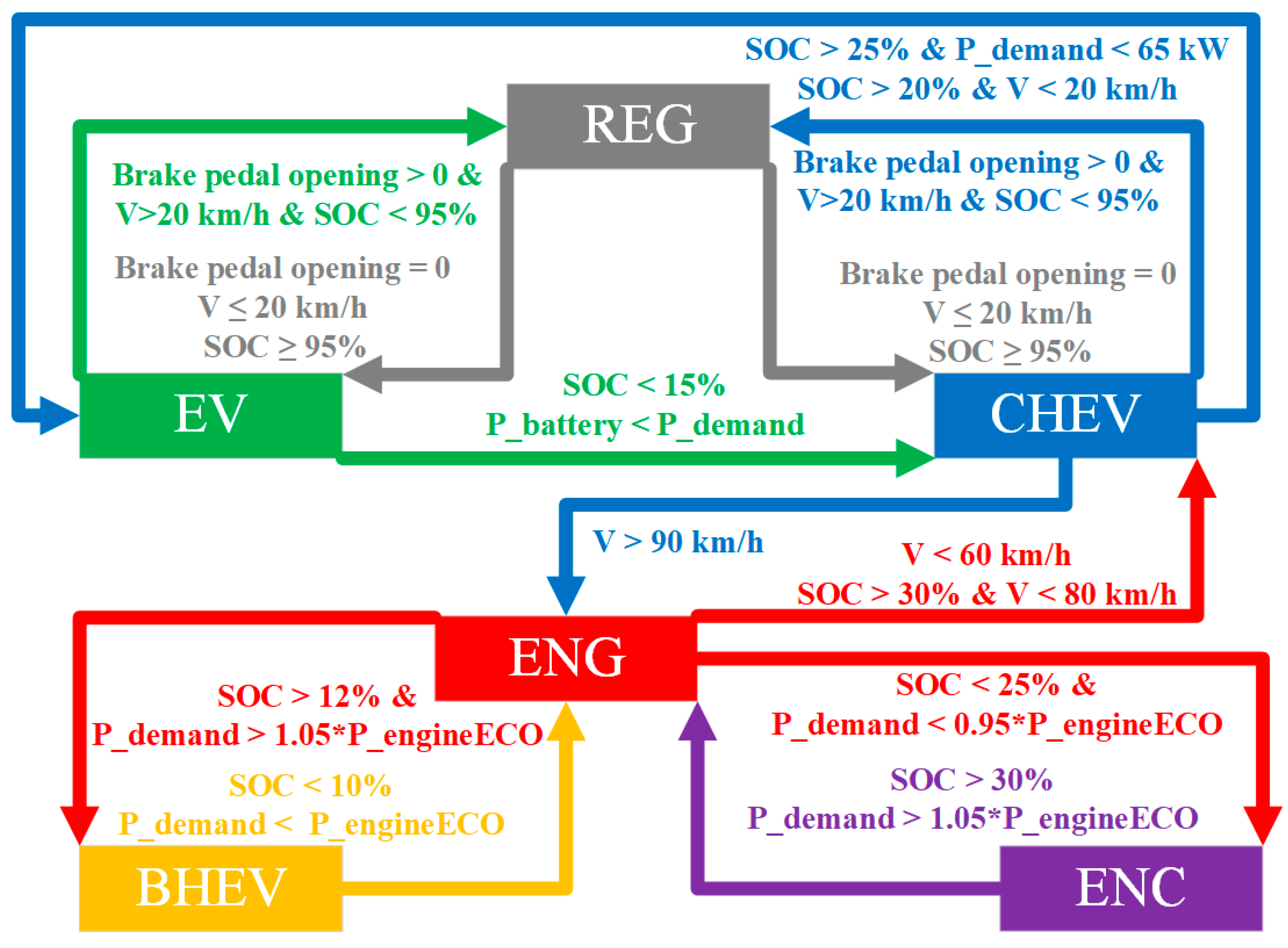
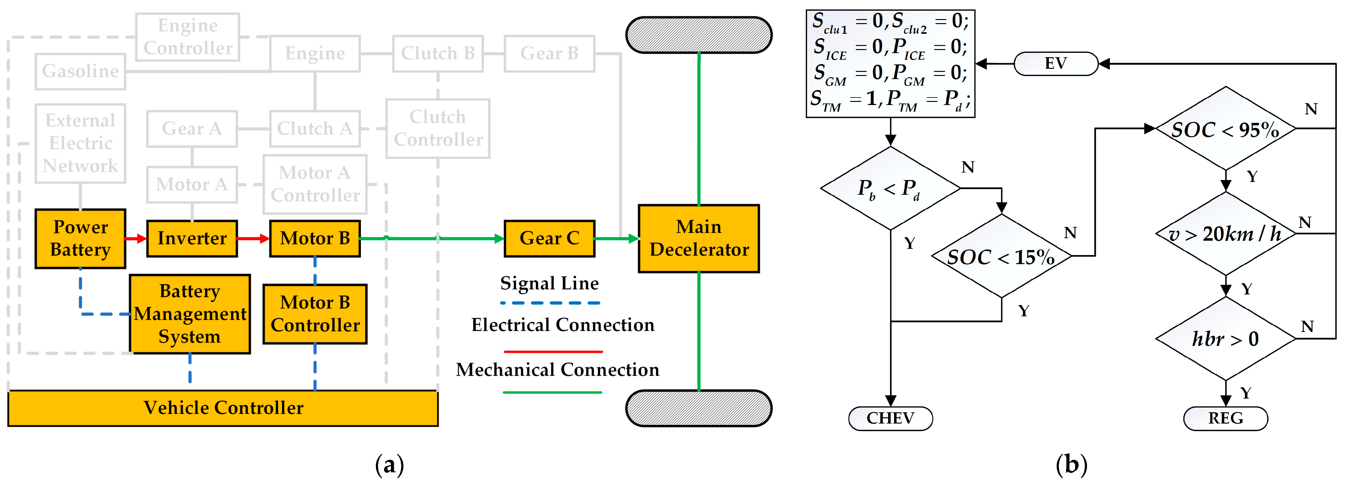
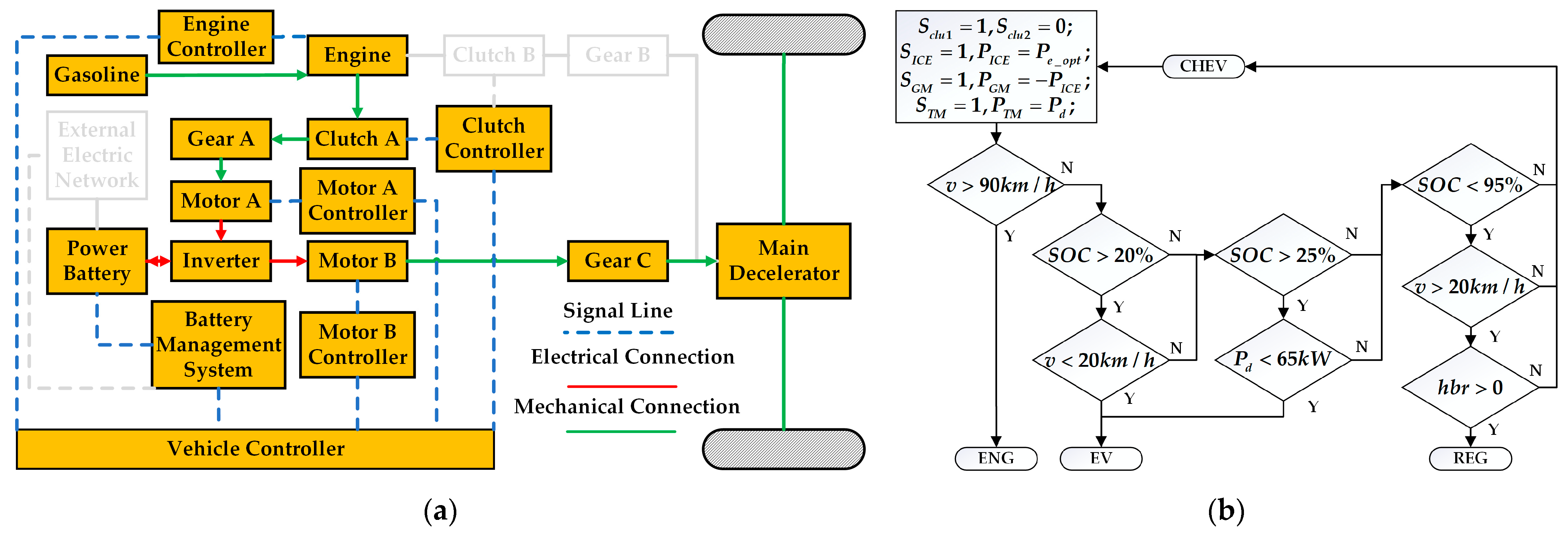
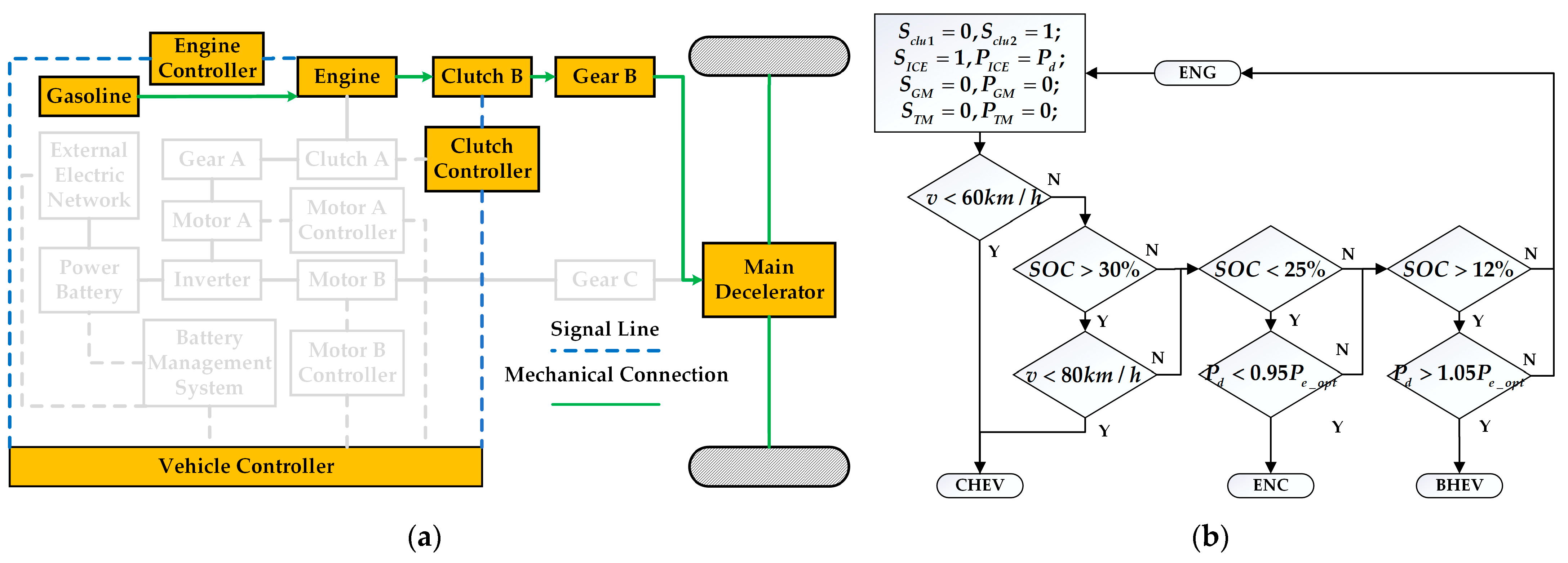
The novel dual-motor plug-in hybrid electric vehicle in this paper combines the features and benefits of pure electric, series, and parallel configurations, increasing the complexity of mode selection and energy distribution among power sources. The inherent complexity of modern hybrid systems precludes the reliable establishment of mode-switching thresholds through empirical engineering judgment alone. For instance, in pure electric mode, energy distribution between motor braking and hydraulic braking can be adjusted. In series hybrid configuration, optimal power allocation between the engine-generator unit and battery pack can be achieved through energy management. Conversely, parallel hybrid operation enables dynamic torque distribution between the internal combustion engine and dual electric traction motors. Since pure electric, series, and parallel modes can generally meet driver demands, determining the optimal operational mode and corresponding energy allocation strategy to maximize overall system performance remains a critical research challenge in hybrid vehicle control.
Although the method based on optimization has excellent fuel economy, the complex operation of the coupled power system of hybrid electric vehicle poses an obstacle to the online application of control strategy. In view of this, some researchers introduce the optimal information in the optimal control into the rule-based strategy, forming a rule extraction method. The control scheme in this area involves multiple logic or mapping rules, which include fuel-saving operations based on global or suboptimal data sets. This approach reduces computational complexity while maintaining energy efficiency. Wang et al. [23] developed a rule extraction method for series-parallel AMT hybrid vehicles, using dynamic positioning optimization to determine the driving mode and shift line. Parallel to this work, Yu et al. [24] established a rule-based control architecture specifically tailored for dual-motor EV powertrains.
The dynamic programming approach exhibits remarkable adaptability, imposing minimal restrictions on both system state equations and performance index formulations, thereby accommodating data-driven system modeling paradigms [25]. Moreover, the fuel consumption optimization problem for hybrid electric vehicles on a given path fits the dynamic programming framework, as it lacks aftereffects or overlapping sub-problems. This makes dynamic programming an ideal approach for solving optimal control problems in hybrid electric vehicles [4]. Primarily, the DP algorithm guarantees global optimality for hybrid electric vehicle energy management along predefined driving cycles, thereby establishing benchmark solutions for heuristic control strategy development. Then, key control parameters can be derived from dynamic optimization results to improve and adjust the control strategy of hybrid electric vehicles [26]. Therefore, this paper adopts the rule-based control strategy to develop the controller of the dual-motor plug-in hybrid electric vehicle, and at the same time optimizes the rule control logic by using the global optimal strategy based on the DP algorithm, thus realizing the adjustment and improvement of the energy management strategy of the dual-motor plug-in hybrid electric vehicle.
The rest of this article is as follows: Section 2 describes the modeling of the power system and rule-based control strategies. Section 3 introduces the control strategy based on DP algorithm, obtains its simulation results, and improves the rule control strategy. The discussion and analysis of the results before and after rule control optimization are described in Section 4. Section 5 summarizes the main conclusions.

2. Hybrid System Modeling

2.1. Powertrain Structure and Vehicle Parameters

Before the research and optimization of control strategy, it is very important to establish a physical model of the powertrain [27]. The powertrain structure of the plug-in hybrid electric vehicle in this paper is shown in Figure 1. The system consists of a gasoline internal combustion engine (ICE), a generating motor (Motor A-GM), a traction motor (Motor B-TM), a power battery pack, two wet multi-plate clutches, and other components.
The ICE’s peak power is 94 kW, and its peak torque is 168.6 Nm. The generating motor (GM) has a peak power of 60 kW and a peak torque of 140 Nm, while the traction motor (TM) offers a peak power of 120 kW and a peak torque of 286 Nm. The battery pack features a capacity of 21.96 kWh and a nominal voltage of 343.1 V. The key powertrain parameters are detailed in Table 1.
Modeling the entire dynamic behavior of hybrid vehicle components, including the ICE, motor, and battery, is highly complex. This research adopts a parsimonious modeling approach by intentionally excluding non-essential variables, thereby reducing the parametric complexity of powertrain component representations and control logic architectures while maintaining sufficient fidelity to capture the HEV’s core dynamic modes (e.g., energy flow characteristics). The same model parameters are applied to both rule-based and DP-based control strategies.

2.2. Component Models

2.2.1. ICE Model

The ICE’s fuel consumption characteristics are quantified through a steady-state modeling approach. The ICE efficiency is defined as follows:
η I C E ( T I C E , n I C E ) = T I C E × n I C E m ˙ f × Q g h v × 100 % ,
where Q g h v represents the heating values of gasoline (J/g), m ˙ f is fuel consumption rate (g/s), T I C E and n I C E represent ICE torque (N·m) and ICE speed (rad/s), respectively.
The ICE fuel consumption can be described by
m e = 0 t   m f ˙ d t L e = m e ρ e ,
where m e and L e are the fuel mass (g) and fuel volume (mL) consumed by the ICE, respectively, and ρ e is the density of gasoline (g/mL).
Test bench data are used to obtain the ICE’s fuel consumption and torque MAP, describing its external performance.
The torque computation algorithm processes two primary inputs—instantaneous ICE rotational velocity and ignition activation signal—to determine the ICE’s output torque characteristics, as schematically represented in Figure 2a. This module implements the following governing equation:
T I C E = f ( α , n I C E ) ,
In this context, α denotes the ICE throttle (ranging from 0% to 100%), n I C E is the ICE speed (RPM), and T I C E is the ICE’s torque output (N·m), calculated based on the ICE speed and throttle lookup table.
The fuel consumption estimation algorithm processes primary inputs including throttle position and ICE rotational speed to determine the instantaneous fuel mass flow rate, as illustrated in Figure 2b. The underlying physical relationship is expressed by the following model:
m f ˙ = f ( α , n I C E ) ,
where m f ˙ denotes the instantaneous fuel consumption rate (g/s), determined by the ICE speed and throttle opening.

2.2.2. Motor Model

In the hybrid system, both GM and TMs can play two roles: (1) as a generator motor, used to save excess energy of the ICE, or maintain battery power, or energy recovery during braking; (2) as a traction motor, used to assist the ICE drive, or start the ICE, or the vehicle uses electric energy to drive.
The TM and GMs are permanent magnet synchronous motors. Because of their fast transient response, only their static characteristics are considered. Their models are described as follows:
T i = m i n T i _ r e q , T i _ d i s _ m a x , T i _ r e q 0 m a x T i _ r e q , T i _ c h g _ m a x , T i _ r e q < 0 T i _ j _ m a x = f n i , S O C i G M , T M , j ( d i s , c h g ) ,
where T i _ r e q represents the motor required torque (N·m), T i _ d i s _ m a x and T i _ c h g _ m a x are the maximum motor torque (N·m) limited by SOC and the motor speed n i (RPM) when PHEV driving and generating, respectively, and T i is the motor torque (N·m).
The output current calculation module can be described mathematically by
I i = n i × T i η i × V i , T i 0 n i × T i × η i V i , T i < 0 η i = f n i , T i , i G M , T M ,
where V i is the motor voltage (V) and I i is the motor current (A). Motor efficiency η i is a function of n i and T i . The efficiency of GM and TM is shown in Figure 3.

2.2.3. Battery Model

The lithium-ion battery is employed in the studied PHEV due to its high energy density. To avoid excessive complexity in the model, a detailed analysis of the power battery’s characteristics and its influencing factors is typically omitted. Instead, the battery’s open-circuit voltage (OCV) and internal resistance (IR) characteristics are typically parameterized as state of charge (SOC)-dependent functions, with their functional relationships empirically determined through laboratory testing. Factors such as temperature fluctuations and battery aging are not accounted for in this model. This functional relationship is illustrated in Figure 4.
Battery power P b a t (W) is related to motor power, as in
P b a t = T i n i × η i h η c h , h { 1 , 1 } ,
η c is the average cycle efficiency of the power converter. n i and T i are the motor speed (rad/s) and torque (N·m), respectively. h depends on the direction of the current power, that is, h = 1 ,     P b a t 0 ; h = 1 , P b a t < 0 .
According to the battery model, P b a t is represented by the following formula:
P b a t = V o c × I b a t I b a t 2   × R b a t R b a t = f b a t _ R ( x S O C ) V o c = f b a t _ O C ( x S O C ) ,
where I b a t is the battery current (A), V o c is the OCV (V), and R b a t is the IR (Ω) depending on the battery SOC and the direction of the current. By solving Equation (8), I b a t can be obtained by the following formula:
I b a t = V o c V o c 2 4 R b a t × P b a t 2 R b a t ,
Then, SOC can be obtained by the following formula:
S O C k + 1 = S O C k V o c _ k + 1 V o c _ k + 1 2 4 R b a t _ k + 1 × P b a t _ k + 1 2 R b a t _ k + 1 × Q c t ,
where Q c is battery capacity (A·h), t is sampling time (h).

2.2.4. Vehicle Dynamics Model

The total driving resistance acting on a vehicle consists of multiple components that collectively oppose its motion. These include rolling resistance generated at the tire-road interface, aerodynamic drag caused by air displacement, grade resistance due to road inclination, and inertial resistance during acceleration. The hybrid powertrain’s electric motor and ICE collectively produce sufficient tractive effort to counteract these resistances through torque generation at the drive wheels. This force equilibrium enables stable vehicle operation across diverse driving conditions, with the energy management system dynamically allocating power sources based on resistance magnitude and operating efficiency. The propulsion system’s capability to overcome these resistances while maintaining drivability and fuel efficiency represents a critical design consideration in hybrid electric vehicle development. This study’s vehicle model is founded on the vehicle travel equilibrium equation:
F t = F f + F w + F i + F j ,
The vehicle’s rolling resistance F f (N·m), air resistance F w (N·m) and slope resistance F i (N·m) are shown as follows:
F f = m g C r c o s θ F w = C d A 21.15 v 2 F i = m g s i n θ ,
where g is the standard acceleration of gravity (m/s2), and C r is rolling friction coefficient. θ is the road slope (°), C d is the air resistance coefficient, A is the front area of the vehicle (m2), v is the speed of vehicle (km/h).
In different vehicle working modes and clutch states, the driving force F t of the vehicle (N·m) is also different, which can be expressed as:
F t = T T M i t m i 0 η T   /   R w h           S c l u 1 = 0   o r   1 ,   S c l u 2 = 0 T I C E i e + T T M i t m   i 0 η T   /   R w h           S c l u 1 = 0 ,   S c l u 2 = 1 ( T I C E + T G M i g m )   i e + T T M i t m   i 0 η T   /   R w h           S c l u 1 = 1 ,   S c l u 2 = 1 ,
where S c l u * = 0 represents the clutch is disengaged, while S c l u * = 1 means the clutch is engaged. i 0 , i e , i t m and i g m represent the main transmission ratio, ICE increase ratio, TM reduction ratio, and GM reduction ratio, respectively. η T is the transmission mechanical transmission efficiency, R w h is the tire radius (m). T I C E , T T M , and T G M represent the ICE torque (N·m), TM torque (N·m), and GM torque (N·m), respectively.
The vehicle’s longitudinal dynamics can be mathematically represented through the following equations of motion:
a = d v d t = F j δ m = ( F t ( F f + F w + F i ) ) δ m v t = 3.6 0 t a d t ,
where the acceleration is a (m/s2), the rotation mass conversion factor is expressed by δ , F j is the acceleration resistance of the vehicle (N·m), the feedback actual velocity is v t (km/h).

2.3. Rule-Based Control Algorithm

Based on the logical threshold rules, threshold values represented by battery SOC, vehicle speed and power of each component are set to control mode switching, including pure electric drive (EV) mode, series hybrid drive (CHEV) mode, pure gasoline drive (ENG) mode, parallel hybrid drive (BHEV) mode, pure gasoline drive with charging (ENC) mode, and regenerative braking energy recovery (REG) mode, as shown in Figure 5. The process of switching the operation modes may involve the change in the operating state of the clutch. The clutch change process has three cases, namely clutch speed synchronization, clutch engagement, and clutch disconnection. Since the state change of the clutch is a transitional process, it is not shown in Figure 5, which mainly describes the steady-state operation modes.

2.3.1. EV Mode

When the battery power is enough, pure electric drive is preferred. By using the characteristics of low speed, high torsion, and high efficiency, the motor can not only fully achieve the purpose of reducing fuel consumption but can also improve the starting power performance. During the EV mode, the vehicle is solely propelled by the traction motor, with all the necessary energy supplied exclusively by the battery packs, as shown in Figure 6.
When the demand power is high or the SOC is low, EV mode will switch to CHEV mode. The mode transition sequence initiates with GM motor activation, followed by clutch A engagement to mechanically couple and crank the ICE. Subsequently, the ICE drives the GM in generator mode before establishing full CHEV operation. When the battery is not fully charged, the braking energy recovery (REG mode) will work once the brake is applied. In REG mode, it can be realized only by changing the positive torque of the TM into negative torque.
Here, P b , P d , h b r , v respectively represent the available battery power, driver demand power, brake pedal opening, and vehicle speed. S c l u * indicates the operational status of the clutch, where S c l u * = 0 means the clutch is disengaged, and S c l u * = 1 means the clutch is engaged. P I C E , P G M , and P T M respectively represent the output power of the ICE, GM, and TM. The variable S * describes the working state of the power components (such as the ICE, GM, and TM). For example, S I C E = 0 indicates the engine is off, while S I C E = 1 signifies the engine is active.

2.3.2. CHEV Mode

When the electric quantity is not abundant, the electric quantity is maintained by series drive mode, as shown in Figure 7. In CHEV mode, the ICE, GM, and TM are started, clutch A is engaged, and clutch B is disconnected. Both the TM and the ICE work together to deliver power to the PHEV, but the power from the ICE is used to maintain or replenish the battery, and it is not directly exported to the wheels. The TM’s output power aligns with that in EV mode, meeting the driver’s power requirements. Therefore, the vehicle speed is independent of the ICE speed, and the SOC of the battery pack will be stable or increased. In addition, the power output of the ICE in this mode is always at its most economical.
When the battery charge is higher than 20% and the speed is very low, or the battery is higher than 25% and the driver’s demand power is low, it will switch to EV mode, because the pure electric mode at this time can meet the driving demand, and does not need to use the ICE for energy conversion to increase additional fuel consumption. During this phase, clutch A is disengaged, followed by sequential shutdown of both the ICE and GM, culminating in the system transitioning to EV mode. When the speed is greater than 90 km/h, in order to directly use the high efficiency range of the ICE, the ICE directly drives the wheel, that is, ENG mode. The mode transition sequence initiates with synchronized speed matching between the ICE and GM. Subsequently, clutch A disengages while clutch B engages, followed by GM deactivation and TM torque termination. The system then stabilizes in ICE-only (ENG) mode with ICE as the sole propulsion source. The conditions for entering energy recovery mode in CHEV mode are the same as in EV mode. At this time, GM and ICE remain unchanged, and only TM is changed to negative torque for power generation. Here, P e _ o p t denote the optimal ICE output power.

2.3.3. ENG Mode

When the vehicle speed is high and the driving power is close to the optimal output power of the ICE, the ENG drive mode is adopted. The ENG mode is consistent with the operation mode of the traditional fuel vehicle, and the ICE power is directly output to the wheel, as shown in Figure 8. When the vehicle is running in series mode (CHEV) and the speed rises to a certain high speed, in order to improve the dynamic performance of the system, the hybrid operation modes (ENC and BHEV) are entered. Because of the short power transmission route in these working modes, less energy is lost in the process of mutual conversion and transmission. In this study, ENG mode is the bridge between CHEV, ENC, and BHEV.
When the speed is below 60 km/h or the SOC is above 40% with the speed reduced, the ICE speed will be decoupled from the wheel and the vehicle will enter CHEV mode. At this time, clutch B is disconnected, the output torque of the TM is used to drive the vehicle, then the GM is started. Combined with the clutch A, the output power of the ICE is transferred to the GM for power generation, and finally the CHEV mode is entered.
When the SOC is less than 25% and the optimal ICE output power is greater than the required power, the excess power is used to charge the battery. At this time, it is only necessary to control the TM to output negative torque and transfer part of the output power of ICE to the TM for power generation, so as to switch to ENC mode.
When the SOC higher than 12% and the required power is also greater than the optimal ICE power, the BHEV mode will be switched to meet the driver’s needs. The switching process of this mode is just the opposite of ENC mode. At this time, TM is controlled to output positive torque, which is used to drive the vehicle together with ICE.

2.3.4. BHEV Mode

In the BHEV mode, the ICE supplies the majority of the energy required for the vehicle, while the TM supplements the remaining power to meet the driver’s demands until the power requirement falls within the ICE’s optimal operating range. The GM is deactivated in this mode to prevent efficiency losses resulting from increased energy circulation. When the battery charge is too low, in order to protect the battery pack, the battery will stop discharging and return to ENG mode. At this time, the TM is controlled to stop outputting torque, and the ENG mode can be entered. The control strategy for switching between energy consumption modes is illustrated in Figure 9.

2.3.5. ENC Mode

In the ENC drive modes, the TM adjusts its own output power according to the driver’s total power demand, and the ICE can still keep working in the high efficiency range. The control strategy of ENC mode is illustrated in Figure 10. In this mode, the recovery of braking energy from regenerative braking is included, as the electrical energy is generated through the TM. The power of energy recovery is related to the opening of the brake pedal and the charging rate of the battery. In this paper, the power corresponding to the charging rate of the battery 1C is selected as the benchmark, which is 20 kW.
The ICE operates within its optimal efficiency range to propel the PHEV, while the excess torque is utilized to activate the TM for power generation. If the power required by the driver is greater than the optimal ICE output power, the vehicle will exit ENC mode and will enter ENG mode. Once the SOC is greater than 30%, there is no need to charge the battery, so it also enters ENG mode. When switching from ENC mode to ENG mode, it can be realized by controlling TM not to output torque.

2.3.6. REG Mode

When the state of charge (SOC) does not exceed 95% and the vehicle speed is not low, the plug-in hybrid electric vehicle can operate in regenerative braking (REG) mode as soon as the brake is applied, and the related control strategy is presented in Figure 11. Whether entering REG mode from CHEV mode or from EV mode, the generator set composed of the ICE and GM maintains the previous operating state, which can avoid frequent changes to the ICE and clutch A.
When the SOC exceeds 95% (battery needs to be protected) or the vehicle speed is lower than 20 km/h (energy recovery power is too low) or the driver does not step on the brake pedal (no intention to slow down), the REG mode will be exited. At this time, the TM can be controlled to enter EV mode or CHEV mode without outputting negative torque for power generation.

3. Control Strategy Based on DP Algorithm

3.1. DP Theory

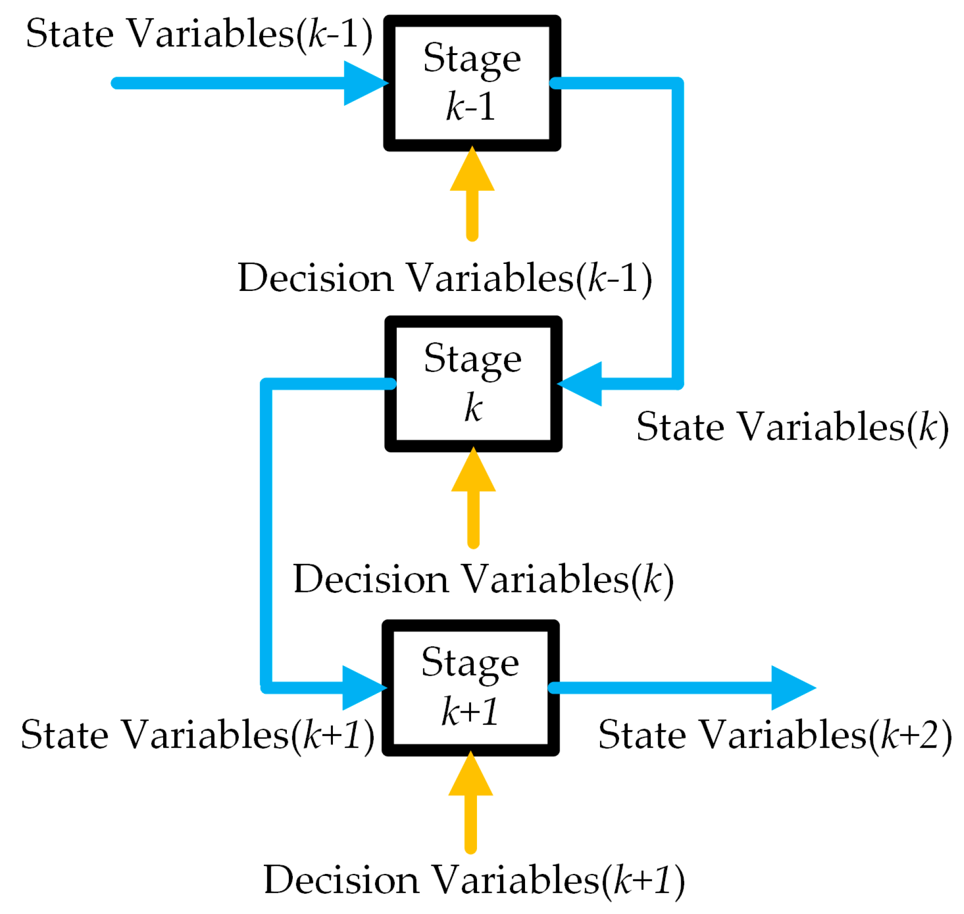
By partitioning the optimization problem into multiple interconnected stages, the DP algorithm employs carefully chosen state variables, control variables, and cost functions to decompose the original problem into a sequence of similar subproblems. Each subproblem’s solution builds on the results of the previous one, and the optimal solution for the final subproblem serves as the global optimum. Figure 12 provides a block diagram of the dynamic programming algorithm’s process [28]. When optimizing the entire process, the initial state is known, so each stage’s decision depends solely on its current state. This allows the optimal strategy and state at each stage to be adjusted to determine the best route. Rule-based control strategies, which often rely on empirical and constrained parameter settings, cannot fully exploit the benefits of PHEVs. In contrast, DP effectively handles constraints and nonlinearities, finding the global optimal solution. The minimum fuel solution for a given driving cycle is obtained by DP through cost function optimization at each operational stage.

3.2. Problem Formulation

The trip is segmented into several interconnected stages based on known future road conditions, with driving information (e.g., speed, acceleration, and battery SOC) known at the start of each stage. Other conditions are treated as state and phase variables. The energy management optimization problem for hybrid vehicles generally aims to minimize comprehensive fuel consumption. As speed demands change over time, different state variables emerge, and their variations significantly affect fuel consumption. Therefore, the battery SOC is designated as the state variable, while the ICE’s torque and speed, along with the driving motor’s torque, are established as the three decision variables in the DP formulation.
Consequently, the state variable x ( k ) at stage k is mathematically defined as the battery state of charge:
x ( k ) = { S O C ( k ) } , k = 0,1 , 2 , , N ,
The control variable u ( k ) at the k-th stage is defined by the ICE torque T I C E k , ICE speed n I C E k and TM torque T T M ( k ) as follows:
u ( k ) = { T I C E k , n I C E k , T T M ( k ) } , k = 0,1 , 2 , , N ,
Plug-in hybrid electric vehicles typically feature higher-capacity batteries, allowing them to curtail fossil fuel consumption by drawing power from the grid. This paper focuses on optimizing the vehicle’s fuel consumption, taking into account the driving cost associated with electric energy consumption. Therefore, the energy management strategy optimization objective minimizes the HEV’s comprehensive vehicle cost. The system’s cumulative cost function J represents the summation of stage-wise cost objectives throughout the optimization horizon. The instantaneous cost function L combines both fuel and electrical energy expenditures at each stage:
J k = k = 0 N L [ x k , u ( k ) ] ,
L x k , u k = ε V f ( k ) + τ W b ( k ) ,
In this equation, V f ( k ) is the fuel consumption of the ICE output torque at the k-th moment (L), ε is the gasoline price (CNY/L), τ is the electricity price (CNY/kWh), and W b ( k ) is the battery’s discharge/charge energy (kWh).
The key power components of the hybrid vehicle must adhere to the following inequality constraints. Prior to torque/power distribution computations, all component physical constraints must be enforced to meet vehicular speed and torque demands, thus guaranteeing driving safety and operational stability.
S O C m i n S O C k S O C m a x n I C E _ m i n n I C E ( k ) n I C E _ m a x T I C E _ m i n T I C E k T I C E _ m a x n G M _ m i n n G M ( k ) n G M _ m a x T G M _ m i n T G M k T G M _ m a x n T M _ m i n n T M ( k ) n T M _ m a x T T M _ m i n T T M k T T M _ m a x n G M k = n I C E k i g m ,     i f   c l u t c h 1 = 1 T G M k = T I C E k / i g m ,     i f   c l u t c h 1 = 1 n I C E k = n T M k / i t m i e ,     i f   c l u t c h 2 = 1 ,
where the subscripts “min” and “max” signify the smallest and largest values of the associated variables, respectively.

3.3. Implementing DP

The driving cycle is segmented into N stages using time steps, and the state transition equations are defined in discrete state space based on the driving cycle’s time sequence.
x k + 1 = f x k , u k ,   k = 0,1 , 2 , , N 1 ,
Equation (18) is recursively applied to evaluate the stage cost function L k + 1 for subsequent states. Under cyclic boundary conditions, the control variable u k U determines the state transition from stage k to k + 1, where U denotes the admissible control set. At each stage, the optimal path for transitioning state variables to the next stage is chosen by assessing the control variables. Thus, the selected optimal path minimizes the system’s total cost objective over the complete operating cycle.
This minimum-cost trajectory is completely specified by the optimal control policy:
U = { u 0 , u 1 , u 2 , , u ( N 1 ) } ,
The DP problem is solved backward to minimize the cost function, with the recursive Equations (22) and (23) describing the sub-problems. For the ( N 1 )-th step:
J N 1 * x ( N 1 ) = min u ( N 1 ) { L [ x N 1 , u ( N 1 ) ] } ,
For the k -th step ( 0 k < N 1 ):
J k * x ( k ) = min u ( k ) { L x k , u k + J k + 1 * x ( k + 1 ) } ,
In this context, J k * x ( k ) denotes the optimal value function representing the minimum cumulative cost from state x ( k ) at stage k to the terminal condition. The state transition follows x k + 1 = f [ x k , u k ] as specified in Equation (23), where u k is the applied control input.

3.4. Simulation Results of DP-Based Control Strategy

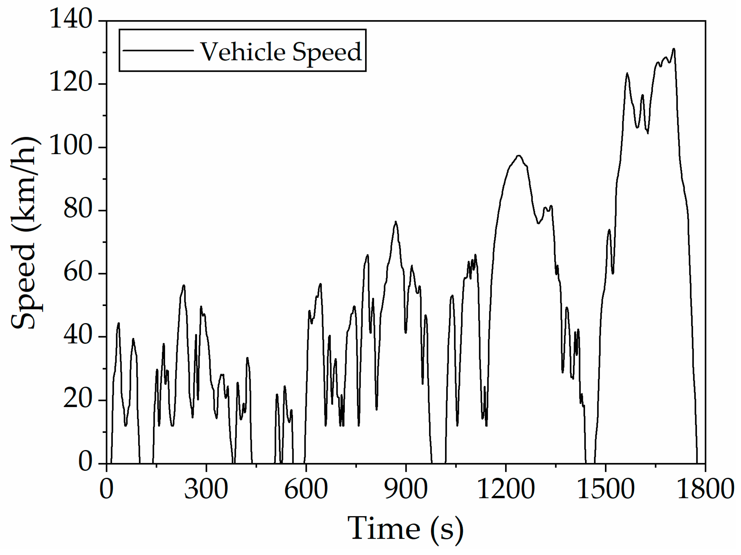
In previous chapters, the state variables, control variables, and cost objective functions for the hybrid vehicle energy management dynamic programming problem have been established. The control strategy based on dynamic programming algorithm is developed on MATLAB (R2022b) software platform. The simulation employs the World Light Vehicle Test Cycle (WLTC), illustrated in Figure 13, spanning 22.73 km over a duration of 1800 s.
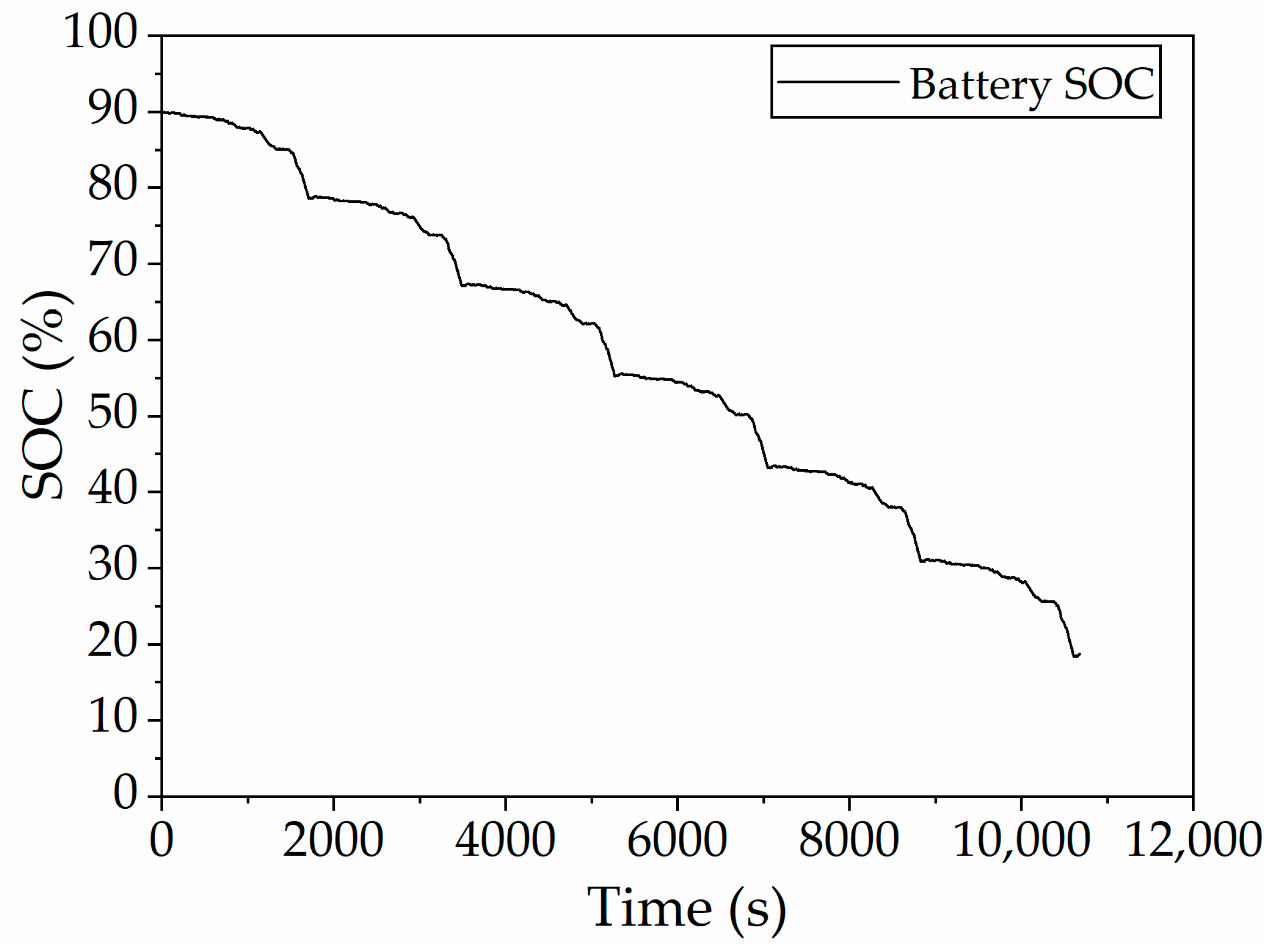
The initial SOC is set to 0.9, and the SOC threshold considering the battery SOC balance based on rule control is 0.15. Six consecutive WLTC driving cycles are simulated. As shown in Figure 14, the SOC drops in a nearly linear manner under DP control, and the energy consumption results are provided in Table 2. In order to simplify the complexity of calculation, a more efficient range of the ICE at 3200 speed is selected for output power generation, and it is obtained that each liter of gasoline can generate 3.0095 kWh of power. According to the mechanical and electrical efficiency loss of generator GM and battery charging, the fuel consumption required for vehicle electricity consumption in this simulation time can be converted to 4.373 L/100 km. The dual-motor plug-in hybrid electric vehicle, optimized with the dynamic programming algorithm, demonstrates a comprehensive energy consumption of 6.423 L/100 km under WLTC conditions.
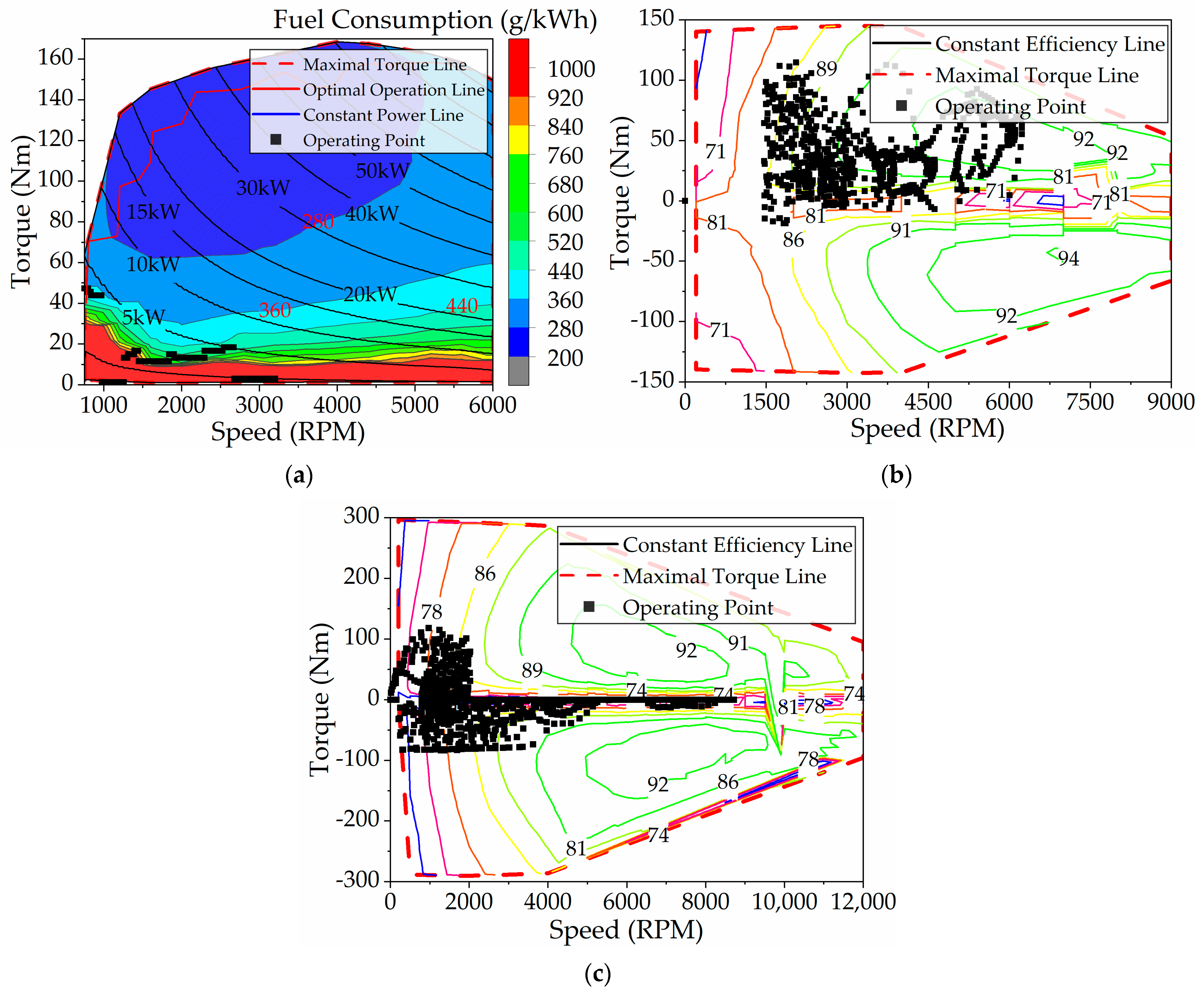
Figure 15 shows the operating points of the ICE, TM, and GM. Notably, the ICE does not operate along the optimal efficiency curve, and its torque output is comparatively modest. The output torque is about 45 N·m at low speed (below 1000 rpm) and about 18 N·m at high speed (above 1000 rpm). In the whole driving cycle, the required torque is mainly provided by the motor, while the ICE accounts for a relatively small proportion. GM works in high efficiency range, and the distribution range of working points is wider than TM. In addition, in the whole working condition, most GMs are in the driving state, and the power generation state is less. The overall efficiency of TM is lower than that of GM, and its working point is mainly within 2000 rpm. Under DP control, when the TM speed exceeds 2000 rpm, the TM hardly outputs the drive torque, only the brake torque. DP control optimizes fuel consumption but necessitates advance knowledge of the driving cycle and substantial computational resources. Therefore, extracting key parameters from DP outcomes can improve rule-based energy management approaches.

3.5. Improved Rule-Based Control Strategy

The DP adopted in this paper is an offline optimization method that pursues global optimization and does not fall under real-time optimization algorithms. The unsuitability of DP for real-time optimization stems from three primary limitations: First, high computational complexity—the state space grows exponentially with the problem scale, making it difficult to complete calculations within a constrained timeframe. Second, heavy reliance on pre-computation—requiring the prior construction of a complete state table, which lacks dynamic adaptability to real-time inputs. Third, the pursuit of global optimization—exhaustive traversal of all possible states’ conflicts with the “rapid response” imperative inherent to real-time optimization.
Within the DP framework, only the optimal output states of vehicle powertrain components and their corresponding operating modes are considered, with no inclusion of mode-switching processes. Consequently, strategy execution incurs no delay. Precisely for this reason, DP yields globally optimal solutions but cannot be directly implemented in vehicle controllers.
In the rule-based control strategy, transitions between vehicle operating modes involve clutch actions encompassing three states: engagement, synchronization, and disengagement. To accurately model this behavior, corresponding clutch and controller models were developed in the simulation environment, with strategy execution delays incorporated. However, due to the brevity of clutch actuation durations, the six operating modes corresponding to the dual clutches in the model are categorized as transient states and thus not exhaustively elaborated in the main text. It is emphasized that the rule-based control strategy retains identical transient operating modes before and after optimization.
The original rule-based energy control strategy is adjusted by using the results of DP optimization, and the optimized rule-based control strategy is obtained, which is mainly reflected in three aspects, as shown in
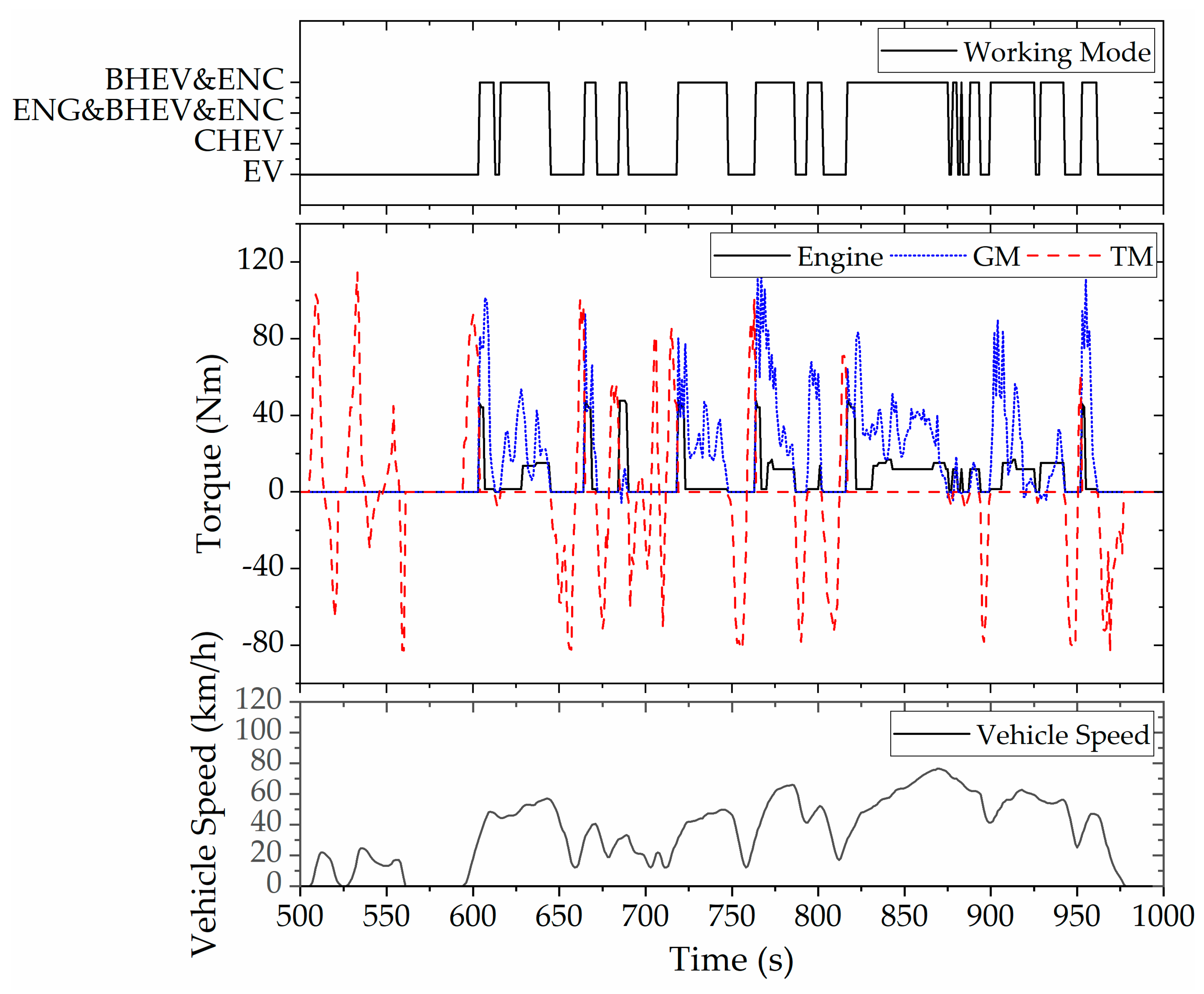
 Figure 16.
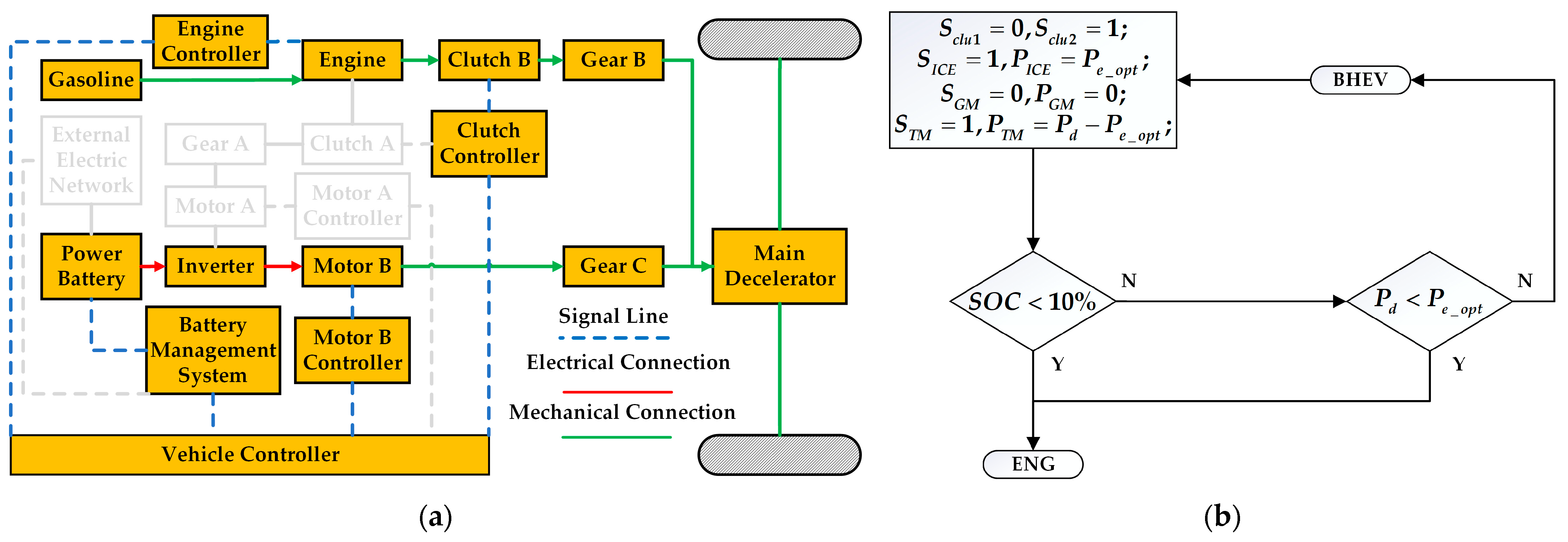
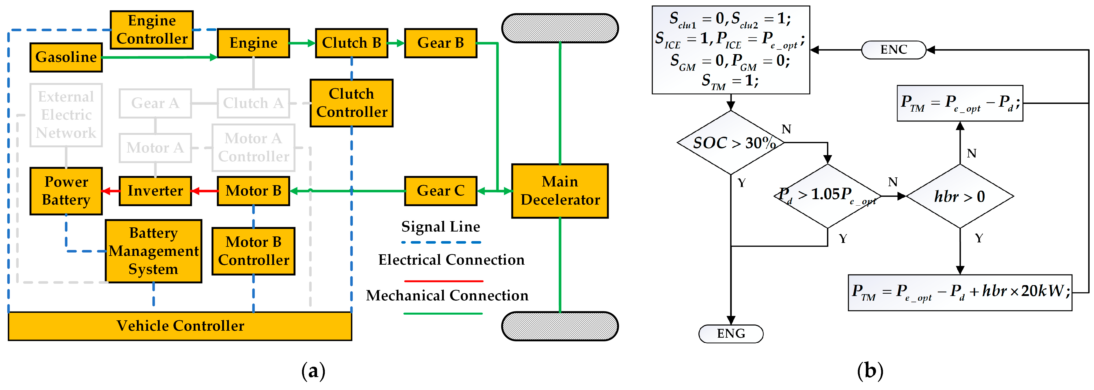
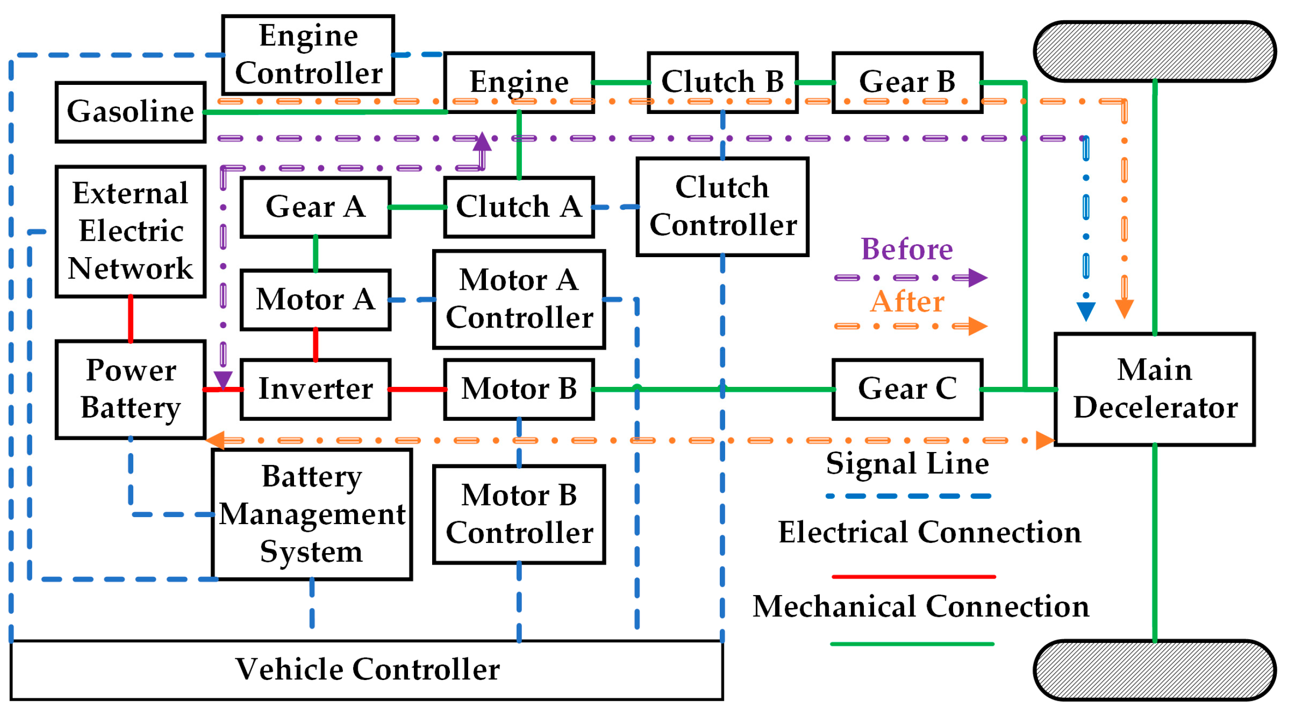
Firstly, it can be seen from the working mode switching curve of the vehicle that the vehicle is hardly driven in series mode but is switched between pure electric mode and parallel mode (ENG, BHEV, and ENC). In addition, when the vehicle is in parallel mode (BHEV and ENC), both the ICE and the GM output power, and the TM does not output torque at this time. It is different from the parallel mode (BHEV and ENC), which is composed of ICE and TM in the previous rule control, and the power source combination of the improved rule control is shown in Figure 17.
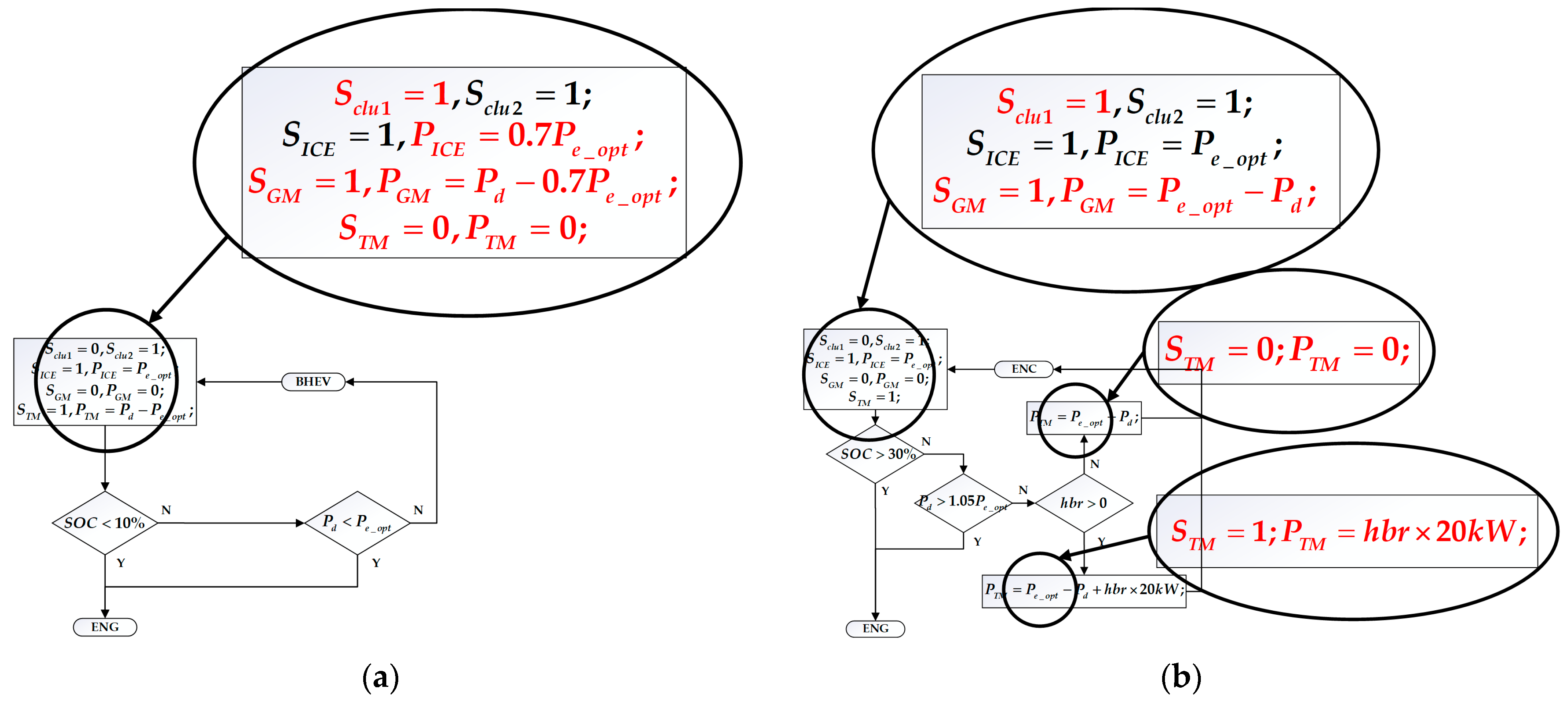
Secondly, from the output torque curve of each power element, it can be seen that when driving in parallel, the output torque of the ICE is not high, instead of working on the optimal economic curve, GM provides more torque. Therefore, when the vehicle is driven in parallel, the proportion of the ICE can be appropriately reduced in the distribution of the driver’s required torque. As shown in Figure 18, under the improved rule strategy, in BHEV mode, the output power of ICE still follows the trend of the optimal economic curve, but its power is reduced to 70%. In ENC mode, because the battery needs to be charged at this time, the output power of ICE is not adjusted, but the TM is changed to GM, as described in Figure 17.
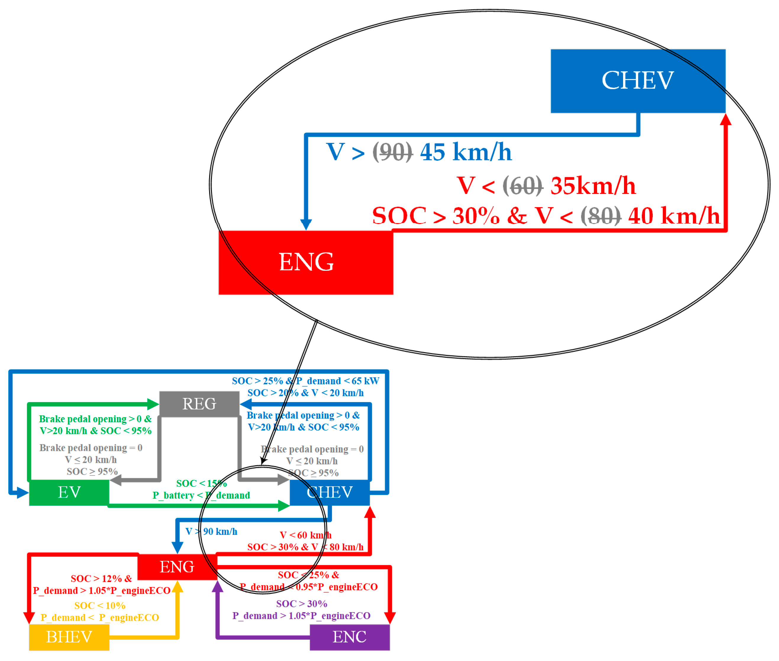
Thirdly, according to the corresponding relationship between vehicle speed and mode switching, under DP control, when the vehicle speed exceeds 40 km/h, the ICE will start to enter the parallel mode. Therefore, compared with the speed threshold of 90 km/h mentioned above, it will be more beneficial to reduce the comprehensive fuel consumption if the ICE is involved in vehicle driving in advance. As shown in Figure 19, the improved rule strategy switches to ENG mode when the vehicle speed threshold is reduced to 45 km/h, and at the same time, the vehicle speed threshold for exiting ENG mode is correspondingly reduced to 35 km/h or 40 km/h.

4. Optimization Results and Discussion

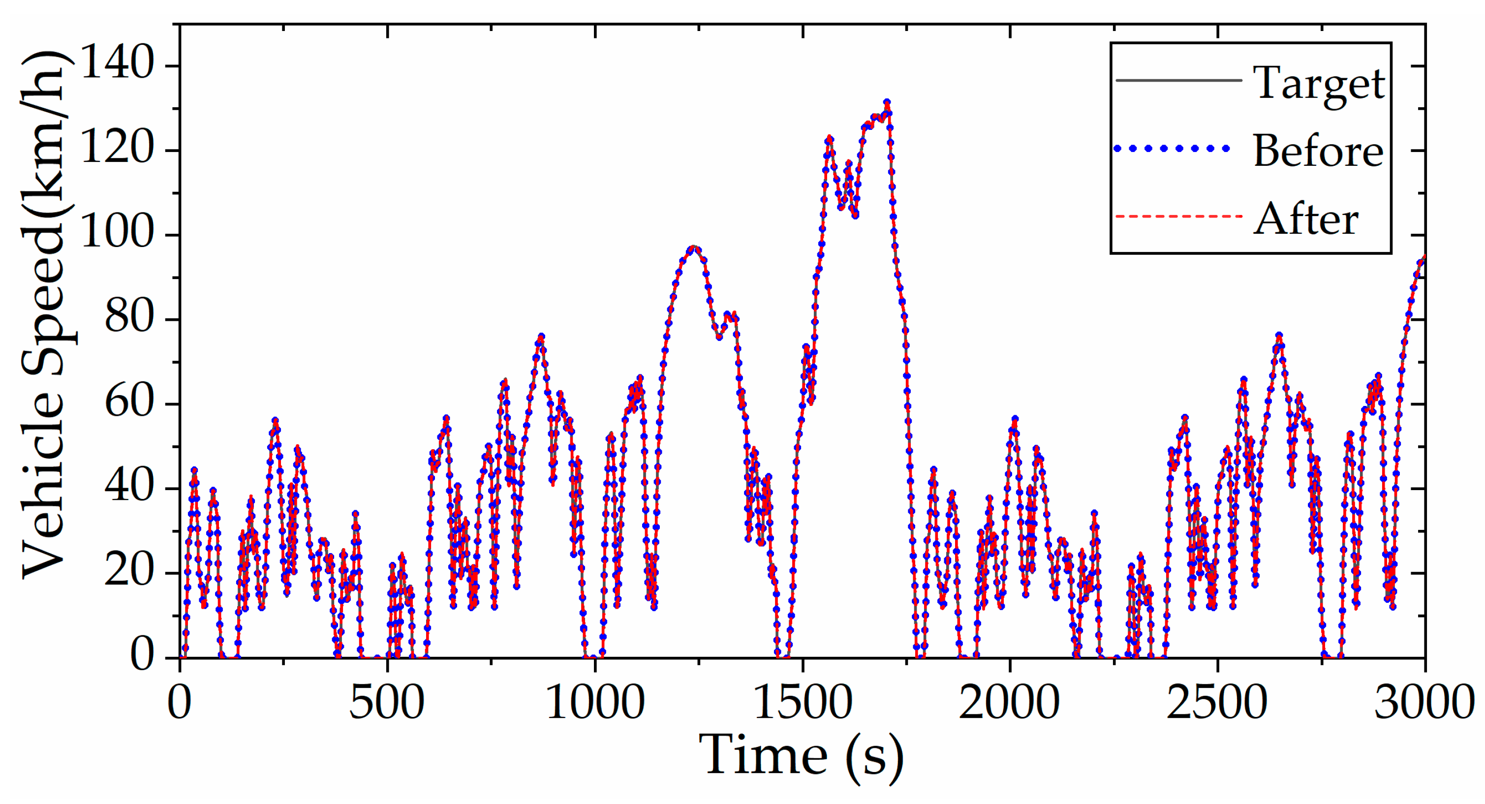
Figure 20 presents a comparative analysis between the simulated PHEV speed profiles (with and without enhanced rule-based control strategy) and the reference WLTC target speed. The results confirm that both control implementations successfully track the prescribed velocity trajectory while satisfying all power demands, demonstrating the robustness of the developed control framework.
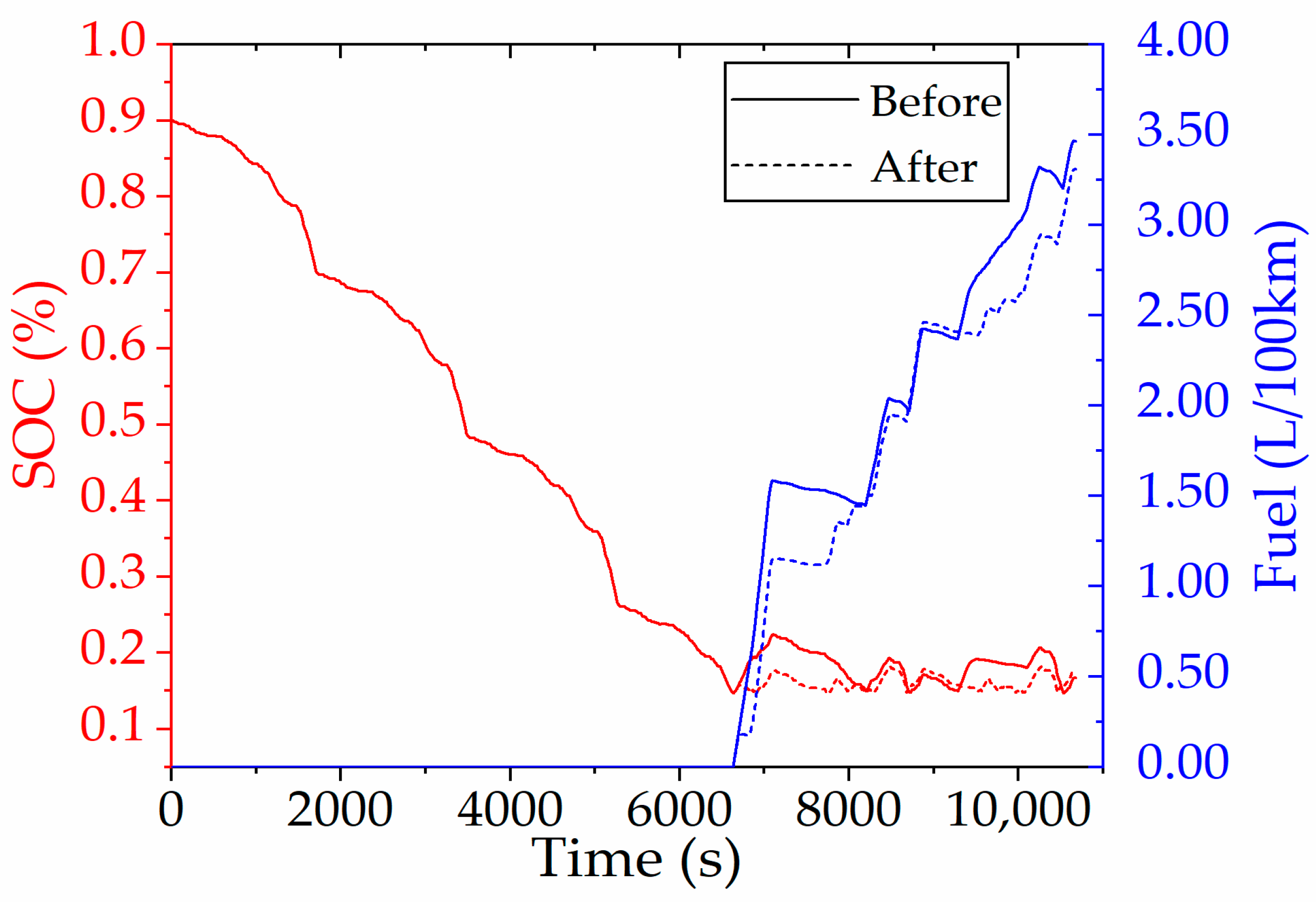
With the initial SOC set to 0.9 before improving the rule-based control strategy, Figure 21 presents the fuel consumption and SOC fluctuations during six continuous driving cycles. The driving distance is 136.379 km and the fuel consumption is 3.463 L/100 km. In rule-based control, the vehicle’s operating state is usually divided into two stages: the charge depleting stage (CD) and the charge sustaining stage (CS), based on the operating state of the battery SOC. Around 6600 s, the PHEV shifted from the CD stage to the CS stage, ending the trip with an SOC of 16.71%. The fuel consumption per 100 km rose by 23.88% compared to DP control, highlighting substantial room for improving the rule-based strategy to achieve better fuel economy.
After the rule-based control strategy is improved, the same driving cycle is carried out and the initial state of charge is also set to 0.9. From the comparison of Figure 21, it can be seen that since PHEV runs in EV mode during the CD stage, the changes in SOC and fuel consumption are consistent with the changes in the control strategy before the improvement. After entering the CS stage, SOC and fuel consumption change more gently, and the final SOC and fuel consumption are 17.87% and 3.307 L/100 km, respectively.
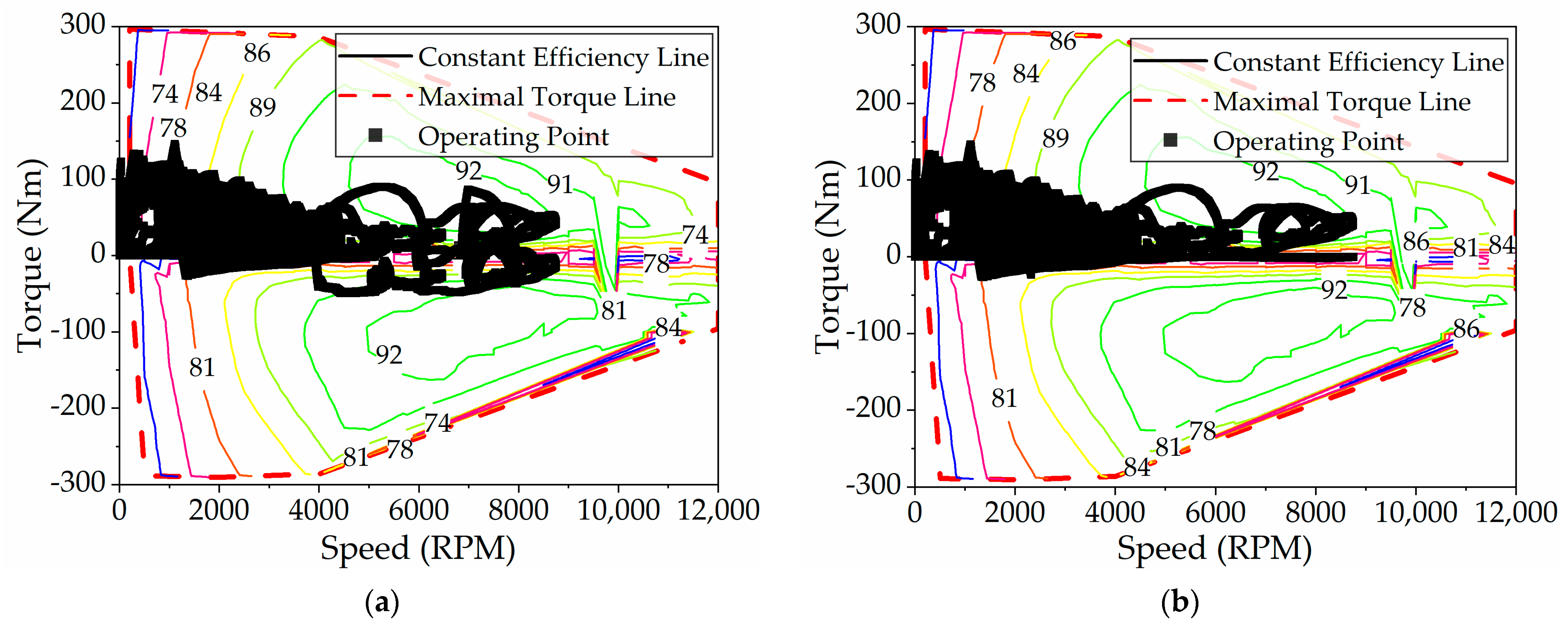
The distribution of TM working points before and after the improvement of rule-based energy strategy is shown in 
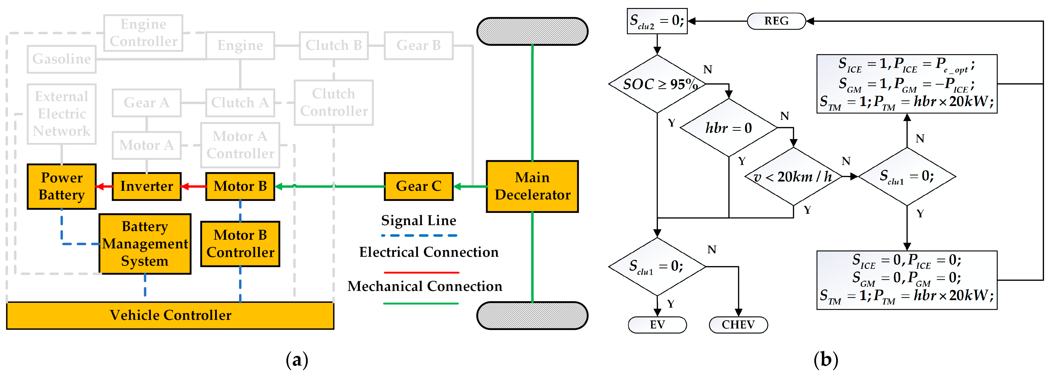
Figure 22. As can be seen from the figure, the operation of TM decreases at high speed, and the TM in particular is hardly in the power generation state. This is because the combination of ICE and GM is used in parallel mode instead of the combination of ICE and TM, while TM is only used in a small amount of braking energy recovery mode.
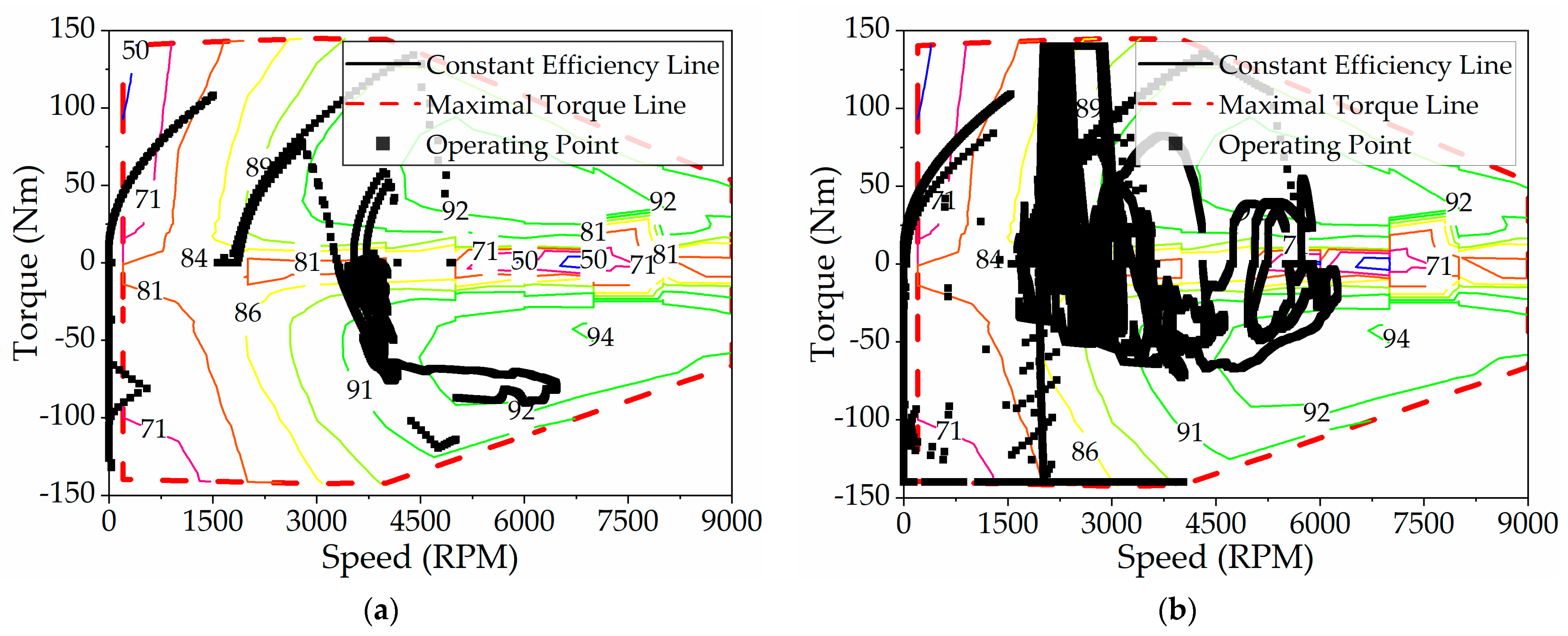
Figure 23 displays the working point distribution of the GM before and after improvement. It is evident that the GM participates more extensively in driving and power generation, operating primarily within the high-efficiency zone. In addition, the overall efficiency of its working point is higher than that of TM. This is because the rated power of GM is smaller than that of TM, its redundant power is lower, and the parallel mode combined with ICE has more energy-saving advantages, which is consistent with the results of DP control.
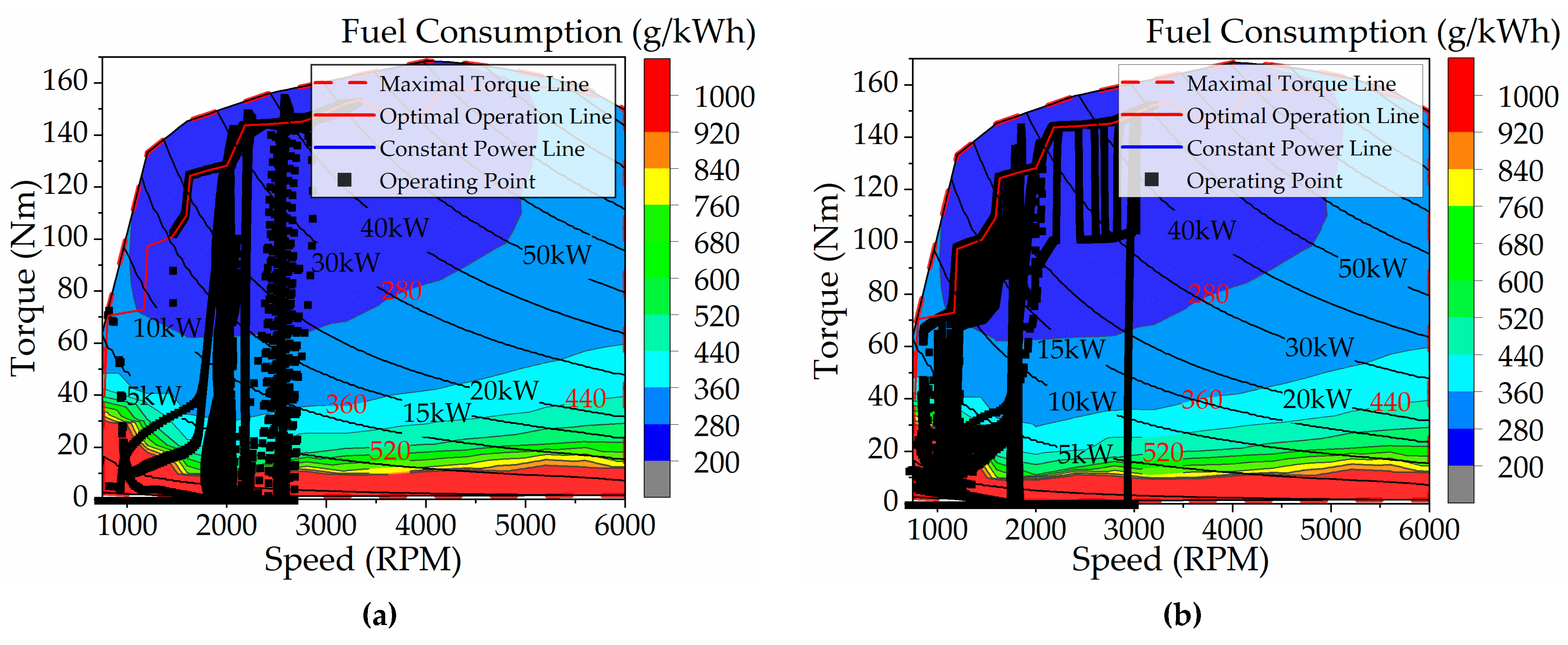
Figure 24 shows the ICE’s operating points. Prior to the rule improvements, the ICE’s operating speeds were mostly between 1800 rpm and 2700 rpm, suggesting that, compared to the DP-based energy management strategy, the ICE ran at higher speeds and needed its output power to be provided later. In addition, the torque at its working point is mainly concentrated on the optimal economic curve, which forces the ICE to output more power. After the improvement of the rules, the working area of the ICE is larger than that before the improvement, and it is in the range of 750 rpm to 3000 rpm, which indicates that the ICE participates in driving the vehicle earlier. The ICE’s working points lie both on the optimal economic curve and slightly below it, demonstrating that the ICE’s output power is efficiently reduced while ensuring improved fuel efficiency.
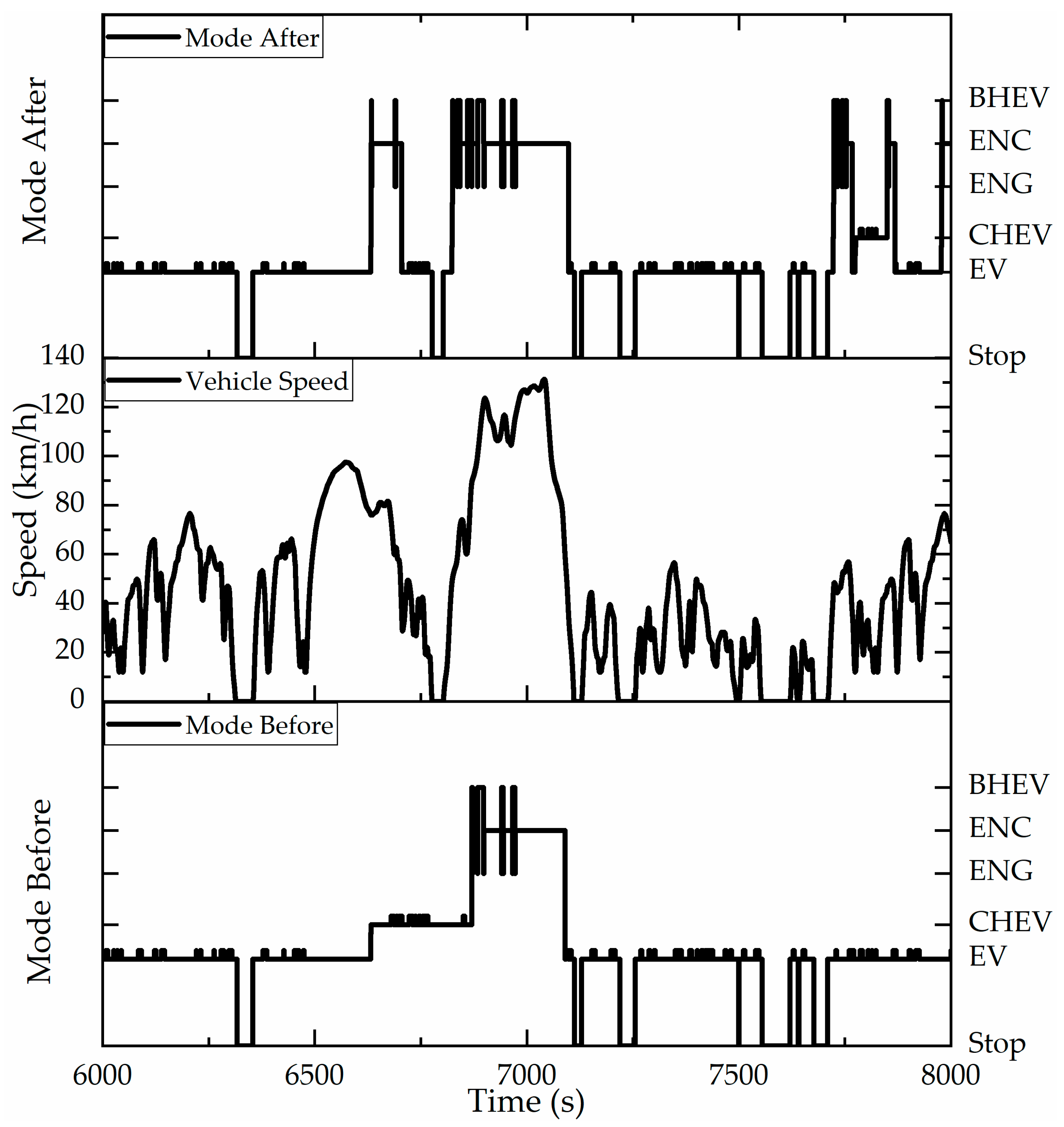
Figure 25 shows the switching of vehicle working modes. It can be seen from the figure that after the improvement of the rules, the CHEV mode is reduced, the BHEV mode and ENC mode are increased, and the running time of the ICE is increased. Using the inspiration of DP optimal control strategy, the vehicle can enter parallel mode driving at medium speed. In addition, the difference between ENG, BHEV, and ENC is that the output torque of GM is positive, negative, and zero, which does not involve complicated switching process. Therefore, the improved rule control strategy does not increase the control difficulty that cannot be achieved, nor does it bring frequent mode switching.
The simulation encompasses six consecutive WLTCs. Given the insufficient temporal resolution in Figure 25, the dynamic transitions between vehicle working mode during the simulation cannot be fully resolved. Therefore, 
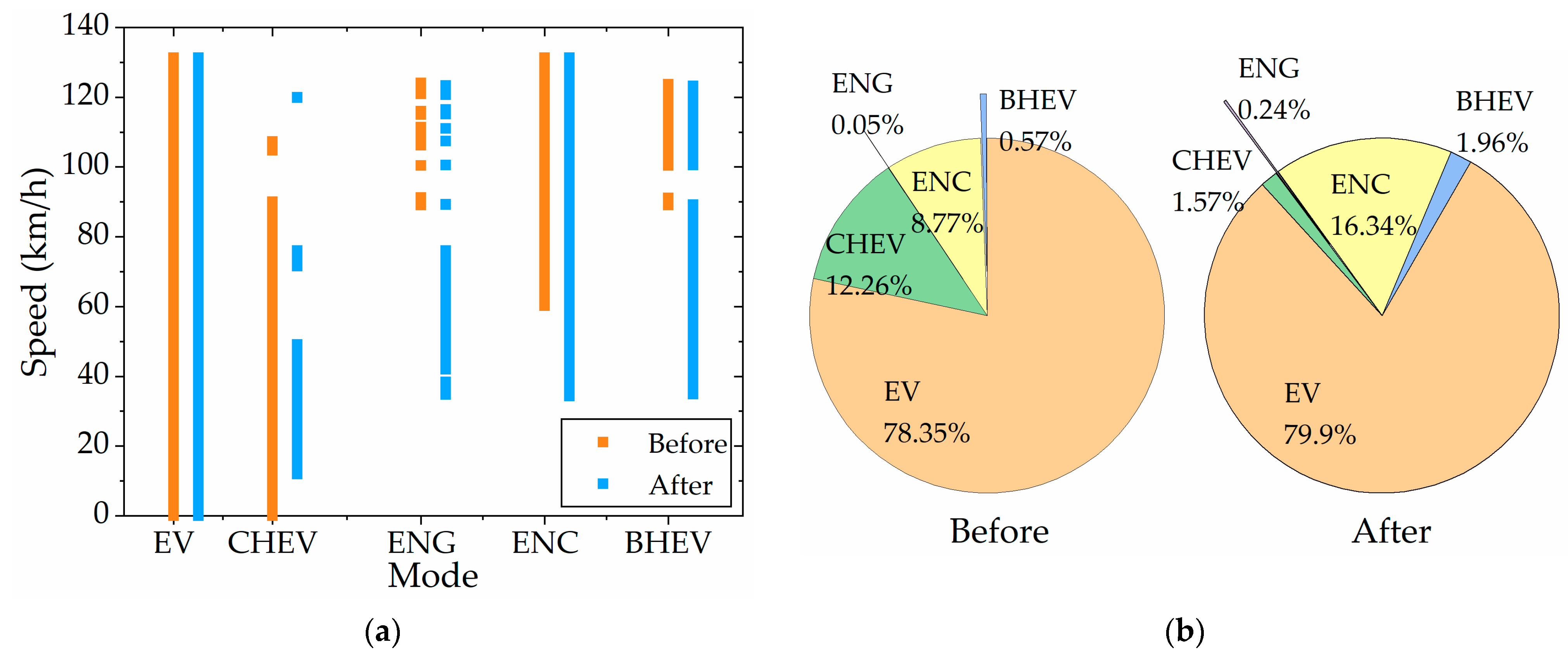
Figure 26 provides a systematic visualization of the spatiotemporal distribution patterns characterizing these working modes. As shown in Figure 26a, the EV mode covers the whole vehicle speed range, so the rule control before and after improvement is the same. The improved rule-based control strategy compresses the distribution of vehicle speed in the CHEV mode, not only when the vehicle speed is lower than 10 km/h but also when the vehicle speed is higher than 50 km/h, so that it will actively enter other modes. The improved rule-based control strategy, whether ENG mode (single power source) or ENC and BHEV mode (multi-power source), has a wider range of engine power output to the wheels, except for at low speeds. As can be seen from Figure 26b, since the improved rule-based control strategy still adopts the same power control method of CD-CS as that of the original rule-based control strategy, the time proportion of EV mode is almost the same. The proportion of CHEV mode changed greatly, from 12.26% before improvement to 1.57% after improvement, while the time proportion of ENC mode increased the most, from 8.77% to 16.34%. However, the time proportion of the ENG mode and BHEV mode increased from 0.05% and 0.57% to 0.24% and 1.96%, respectively. That is, the time when CHEV mode was originally adopted was replaced by ENC, ENG, and BHEV mode.
Table 3 compares the performance of different control strategies. After improving the rule-based strategy, the fuel consumption for six consecutive driving cycles is 4.423 L/100 km, with a final SOC of 17.87%. Fuel consumption per 100 km decreased by 4.504%, and electricity consumption decreased by 1.580%, leading to a 2.853% reduction in comprehensive energy consumption per 100 km. Nevertheless, fuel consumption per 100 km is still 38.010% higher than DP control, and electricity consumption is 1.130% higher.

5. Conclusions

In this paper, the dual-motor PHEV is examined, and the control strategy for the hybrid electric system is developed and explored using a model-based development methodology.
Within the MATLAB/Simulink framework, the key components and controller of the hybrid electric vehicle are modeled. The control strategy is designed based on the vehicle’s operational modes. The DP-based energy management strategy is explored, and an optimal control strategy is developed using MATLAB (R2022b). The vehicle’s working modes and torque distribution are analyzed, and the control strategy is extracted and refined using the optimal control strategy.
(1)
The optimized internal combustion engine (ICE) operating point is not only near the fuel economy curve but it also reduces the output power of the internal combustion engine (ICE).
(2)
After optimization, the working point efficiency of the dual-motor is improved and the cooperation with the internal combustion engine (ICE) is better.
(3)
The optimized working mode switch is more active, making full use of the advantages of various working modes and improving the economy of the system.
The findings show that the DP-based energy management strategy improves the allocation and torque distribution of power components in various operating modes, optimizes the timing of mode switching, and significantly enhances the fuel economy of PHEVs. Fuel consumption per 100 km decreased by 4.504%, and electricity consumption per 100 km decreased by 1.580%, leading to a 2.853% reduction in comprehensive energy consumption per 100 km.
The proposed application framework of the DP algorithm-enhanced rule-based strategy can be extended to other passenger or commercial vehicle models, demonstrating strong commercialization potential. Furthermore, this methodology provides a template for developing energy management systems in emerging hybrid architectures, including hydrogen-fueled hybrids. Although the DP algorithm, as an offline global optimization method, cannot be directly deployed in vehicle controllers, it can still identify local–global optima within constrained temporal and spatial domains, enabling real-time optimization processes—a key direction for our future research. Meanwhile, leveraging the global optimal benchmark derived from DP allows the formulation of diverse rule-based control strategies. By generating training datasets under various rule-based strategies, reinforcement learning can extend multi-objective optimization capabilities across diverse driving styles, fuel consumption, and electricity usage, thereby automating calibration engineering tasks. This will constitute a primary focus of our subsequent work.

Author Contributions

Conceptualization, S.Z., J.Z. and Y.L.; methodology, Y.Y. and Y.Z.; software, J.P.; validation, S.Z. and X.F.; formal analysis, J.Z.; investigation, S.Z.; resources, Y.Y.; data curation, Y.Z.; writing—original draft preparation, S.Z.; writing—review and editing, J.Z., Y.L. and X.F.; visualization, S.Z. and J.P.; supervision, Y.Y.; project administration, Y.Z.; funding acquisition, Y.L. All authors have read and agreed to the published version of the manuscript.

Funding

This research was funded by the National Key Technologies Research and Development Program of China, grant number 2022YFB3403202.

Data Availability Statement

Data are contained within the article.

Conflicts of Interest

Author Yunshan Zhou was employed by the company The Hunan Jianglu & Rongda Vehicle Transmission Co., Ltd. The remaining authors declare that the research was conducted in the absence of any commercial or financial relationships that could be construed as a potential conflict of interest.

Abbreviations

PHEVPlug-in hybrid electric vehicle
HEVHybrid electric vehicle
ICEInternal combustion engine
TMTraction motor
GMGenerator motor
EVPure electric drive
CHEVSeries hybrid drive
ENGPure gasoline drive
BHEVParallel hybrid drive
ENCPure gasoline drive with charging
REGRegenerative braking energy recovery
DPDynamic programming
WLTCWorldwide harmonized light vehicles test cycle
PMPPontryagin’s minimum principle
PSOParticle swarm optimization
SASimulated annealing
MPCModel predictive control
ECMSEquivalent consumption minimization strategy
SOCState of charge
AMTAutomated mechanical transmission
OCVOpen-circuit voltage
IRInternal resistance of the battery
CNYChinese Yuan
CDcharge depleting
CScharge sustaining
Symbols
Q g h v Heating values of gasoline
m ˙ f Fuel consumption rate
T I C E ICE speed
n I C E ICE torque
η I C E ICE efficiency
m e Fuel mass consumed by the ICE
L e Fuel volume consumed by the ICE
ρ e Density of gasoline
α ICE throttle opening
T i _ r e q Motor required torque
T i _ j _ m a x Maximum motor torque limited by SOC
T i _ d i s _ m a x Maximum motor torque limited by SOC when PHEV driving
T i _ c h g _ m a x Maximum motor torque limited by SOC when PHEV generating
T i Motor torque
n i Motor speed
V i Motor voltage
I i Motor current
η i Motor efficiency
i Choose between GM and TM
j Choose between discharging and charging of the battery
P b a t Battery power
η c Average cycle efficiency of the power converter
h Direction of the current power
I b a t Battery current
V o c Open-circuit voltage
R b a t Internal resistance
Q c Battery capacity
t Sampling time
F f Rolling resistance
F w Air resistance
F i Slope resistance
F j Acceleration resistance
F t Driving force
g Standard acceleration of gravity
C r Rolling friction coefficient
θ Road slope
C d Air resistance coefficient
A Front area of the vehicle
v Speed of vehicle
i 0 Main decelerator ratio
i t m TM reduction ratio
i g m GM reduction ratio
i e ICE increase ratio
η T Transmission mechanical transmission efficiency
R w h Tire radius
S c l u Clutch status
a Acceleration of the vehicle
v t Feedback actual velocity of vehicle
δ Rotation mass conversion factor
x State variable
L Stage cost objective function
J Cumulative cost objective function
J * Optimal cumulative cost objective function
u Control variable
k k-th stage in DP
N Total number of stages in DP
ε Gasoline price
τ Electricity price
V f Fuel consumption in DP algorithm
W b Battery’s discharge or charge energy

References

  1. Wang, M.X.; Wang, Y.J.; Chen, L.; Yang, Y.Q.; Li, X. Carbon emission of energy consumption of the electric vehicle development scenario. Environ. Sci. Pollut. Res. 2021, 28, 42401–42413. [Google Scholar] [CrossRef]
  2. Yang, C.; Du, X.L.; Wang, W.D.; Yuan, L.J.; Yang, L.Q. Variable optimization domain-based cooperative energy management strategy for connected plug-in hybrid electric vehicles. Energy 2024, 290, 130206. [Google Scholar] [CrossRef]
  3. Liu, Y.G.; Wu, Y.T.; Wang, X.Y.; Li, L.; Zhang, Y.J.; Chen, Z. Energy management for hybrid electric vehicles based on imitation reinforcement learning. Energy 2023, 263, 125890. [Google Scholar] [CrossRef]
  4. Lue, X.Q.; He, S.J.; Xu, Y.Z.; Zhai, X.R.; Qian, S.C.; Wu, T.; Wangpei, Y.Q. Overview of improved dynamic programming algorithm for optimizing energy distribution of hybrid electric vehicles. Electr. Power Syst. Res. 2024, 232, 110372. [Google Scholar] [CrossRef]
  5. Saiteja, P.; Ashok, B. Critical review on structural architecture, energy control strategies and development process towards optimal energy management in hybrid vehicles. Renew. Sustain. Energy Rev. 2022, 157, 112038. [Google Scholar] [CrossRef]
  6. Marzougui, H.; Kadri, A.; Martin, J.P.; Amari, M.; Pierfederici, S.; Bacha, F. Implementation of energy management strategy of hybrid power source for electrical vehicle. Energy Convers. Manag. 2019, 195, 830–843. [Google Scholar] [CrossRef]
  7. Wang, Y.J.; Sun, Z.D.; Chen, Z.H. Development of energy management system based on a rule-based power distribution strategy for hybrid power sources. Energy 2019, 175, 1055–1066. [Google Scholar] [CrossRef]
  8. Peng, J.K.; He, H.W.; Xiong, R. Rule based energy management strategy for a series-parallel plug-in hybrid electric bus optimized by dynamic programming. Appl. Energy 2017, 185, 1633–1643. [Google Scholar] [CrossRef]
  9. Fu, Y.; Fan, Z.K.; Lei, Y.L.; Wang, X.L.; Sun, X.H. Integrated Optimization of Component Parameters and Energy Management Strategies for A Series-Parallel Hybrid Electric Vehicle. Automot. Innov. 2024, 7, 492–506. [Google Scholar] [CrossRef]
  10. Yi, F.Y.; Lu, D.G.; Wang, X.M.; Pan, C.F.; Tao, Y.X.; Zhou, J.M.; Zhao, C.L. Energy Management Strategy for Hybrid Energy Storage Electric Vehicles Based on Pontryagin’s Minimum Principle Considering Battery Degradation. Sustainability 2022, 14, 1214. [Google Scholar] [CrossRef]
  11. Lin, X.Y.; Li, K.L.; Wang, L.M. A driving-style-oriented adaptive control strategy based PSO-fuzzy expert algorithm for a plug-in hybrid electric vehicle. Expert Syst. Appl. 2022, 201, 117236. [Google Scholar] [CrossRef]
  12. Wang, B.; Xu, J.; Cao, B.G.; Ning, B. Adaptive mode switch strategy based on simulated annealing optimization of a multi-mode hybrid energy storage system for electric vehicles. Appl. Energy 2017, 194, 596–608. [Google Scholar] [CrossRef]
  13. Hu, J.Y.; Li, J.Q.; Hu, Z.Y.; Xu, L.F.; Ouyang, M.G. Power distribution strategy of a dual-engine system for heavy-duty hybrid electric vehicles using dynamic programming. Energy 2021, 215, 118851. [Google Scholar] [CrossRef]
  14. Yang, Y.L.; Pei, H.X.; Hu, X.S.; Liu, Y.G.; Hou, C.; Cao, D.P. Fuel economy optimization of power split hybrid vehicles: A rapid dynamic programming approach. Energy 2019, 166, 929–938. [Google Scholar] [CrossRef]
  15. Tang, X.L.; Duan, Z.W.; Hu, X.S.; Pu, H.Y.; Cao, D.P.; Lin, X.K. Improving Ride Comfort and Fuel Economy of Connected Hybrid Electric Vehicles Based on Traffic Signals and Real Road Information. IEEE Trans. Veh. Technol. 2021, 70, 3101–3112. [Google Scholar] [CrossRef]
  16. Sarvaiya, S.; Ganesh, S.; Xu, B. Comparative analysis of hybrid vehicle energy management strategies with optimization of fuel economy and battery life. Energy 2021, 228, 120604. [Google Scholar] [CrossRef]
  17. Li, Y.; Jiao, X.H. Energy management strategy for hybrid electric vehicles based on adaptive equivalent consumption minimization strategy and mode switching with variable thresholds. Sci. Prog. 2020, 103. [Google Scholar] [CrossRef]
  18. Guo, N.Y.; Zhang, X.D.; Zou, Y.; Guo, L.X.; Du, G.D. Real-time predictive energy management of plug-in hybrid electric vehicles for coordination of fuel economy and battery degradation. Energy 2021, 214, 119070. [Google Scholar] [CrossRef]
  19. Lu, X.Q.; Wu, Y.B.; Lian, J.; Zhang, Y.Y.; Chen, C.; Wang, P.S.; Meng, L.Z. Energy management of hybrid electric vehicles: A review of energy optimization of fuel cell hybrid power system based on genetic algorithm. Energy Convers. Manag. 2020, 205, 112474. [Google Scholar] [CrossRef]
  20. Yan, F.W.; Wang, J.H.; Du, C.Q.; Hua, M. Multi-Objective Energy Management Strategy for Hybrid Electric Vehicles Based on TD3 with Non-Parametric Reward Function. Energies 2023, 16, 74. [Google Scholar] [CrossRef]
  21. Lian, R.Z.; Tan, H.C.; Peng, J.K.; Li, Q.; Wu, Y.K. Cross-Type Transfer for Deep Reinforcement Learning Based Hybrid Electric Vehicle Energy Management. IEEE Trans. Veh. Technol. 2020, 69, 8367–8380. [Google Scholar] [CrossRef]
  22. Xu, F.G.; Shen, T.L. Look-Ahead Prediction-Based Real-Time Optimal Energy Management for Connected HEVs. IEEE Trans. Veh. Technol. 2020, 69, 2537–2551. [Google Scholar] [CrossRef]
  23. Wang, J.N.; Wang, J.; Wang, Q.N.; Zeng, X.H. Control rules extraction and parameters optimization of energy management for bus series-parallel AMT hybrid powertrain. J. Frankl. Inst.-Eng. Appl. Math. 2018, 355, 2283–2312. [Google Scholar] [CrossRef]
  24. Yu, X.; Lin, C.; Zhao, M.J.; Yi, J.; Su, Y.; Liu, H.M. Optimal energy management strategy of a novel hybrid dual-motor transmission system for electric vehicles. Appl. Energy 2022, 321, 119395. [Google Scholar] [CrossRef]
  25. Zhang, X.H.; Liu, L.; Dai, Y.L.; Lu, T.H. Experimental investigation on the online fuzzy energy management of hybrid fuel cell/battery power system for UAVs. Int. J. Hydrogen Energy 2018, 43, 10094–10103. [Google Scholar] [CrossRef]
  26. Geng, W.R.; Lou, D.M.; Wang, C.; Zhang, T. A cascaded energy management optimization method of multimode power-split hybrid electric vehicles. Energy 2020, 199, 117224. [Google Scholar] [CrossRef]
  27. Chen, H.B.; Niu, S.Y.; Shao, Z.Y.; Jian, L.N. Recognizing multitype misalignments in wireless EV chargers with orientation-sensitive coils: A data-driven strategy using improved ResNet. IEEE Trans. Ind. Inform. 2024, 20, 280–290. [Google Scholar] [CrossRef]
  28. Tian, Y.; Liu, J.Q.; Yao, Q.Q.; Liu, K. Optimal Control Strategy for Parallel Plug-in Hybrid Electric Vehicles Based on Dynamic Programming. World Electr. Veh. J. 2021, 12, 85. [Google Scholar] [CrossRef]
Figure 1. Configuration of the hybrid powertrain.
Electronics 14 01450 g001
Figure 2. ICE torque and fuel consumption map. (a) ICE torque map; (b) ICE fuel consumption map.
Electronics 14 01450 g002
Figure 3. Motor efficiency map. (a) Motor A-GM; (b) Motor B-TM.
Electronics 14 01450 g003
Figure 4. Relationship between OCV/IR and the SOC.
Electronics 14 01450 g004
Figure 5. Rule-based control strategy.
Electronics 14 01450 g005
Figure 6. Control strategy in EV mode. (a) Energy flow; (b) control flow.
Electronics 14 01450 g006
Figure 7. Control strategy in CHEV mode. (a) Energy flow; (b) control flow.
Electronics 14 01450 g007
Figure 8. Control strategy in ENG mode. (a) Energy flow; (b) control flow.
Electronics 14 01450 g008
Figure 9. Control strategy in BHEV mode. (a) Energy flow; (b) control flow.
Electronics 14 01450 g009
Figure 10. Control strategy in ENC mode. (a) Energy flow; (b) control flow.
Electronics 14 01450 g010
Figure 11. Control strategy in REG mode. (a) Energy flow; (b) control flow.
Electronics 14 01450 g011
Figure 12. Block diagram of DP algorithm process.
Electronics 14 01450 g012
Figure 13. The speed-time profile diagram of the WLTC driving cycle.
Electronics 14 01450 g013
Figure 14. Battery SOC of six times WLTC drive cycles under DP control.
Electronics 14 01450 g014
Figure 15. Working point of the power elements under DP control. (a) ICE; (b) GM; (c) TM.
Electronics 14 01450 g015
Figure 16. Vehicle working mode and torque distribution of power elements under DP control in the WLTC.
Electronics 14 01450 g016
Figure 17. Improvement of rule-based control strategy in energy flow.
Electronics 14 01450 g017
Figure 18. Improvement of rule-based control strategy in control flow. (a) BHEV mode; (b) ENC mode.
Electronics 14 01450 g018
Figure 19. Improvement of rule-based control strategy in mode switching threshold.
Electronics 14 01450 g019
Figure 20. Speed tracking comparison between the baseline rule-based strategy and the DP-enhanced rule-based strategy under WLTC conditions.
Electronics 14 01450 g020
Figure 21. Comparison of the SOC and fuel consumption.
Electronics 14 01450 g021
Figure 22. Comparison of TM operating points. (a) Before; (b) after.
Electronics 14 01450 g022
Figure 23. Comparison of GM operating points. (a) Before; (b) after.
Electronics 14 01450 g023
Figure 24. Comparison of ICE operating points. (a) Before; (b) after.
Electronics 14 01450 g024
Figure 25. Comparison of vehicle working mode switching.
Electronics 14 01450 g025
Figure 26. Comparison of working mode distributions across speed ranges and drive cycles. (a) Spatial distribution; (b) time proportion.
Electronics 14 01450 g026
Table 1. Main parameters of the powertrain.
SymbolDescriptionValue
mVehicle mass1650 kg
AFrontal area2.638 m2
CdAir resistance coefficient0.382
RwhTire radius0.335 m
i0Main decelerator ratio3.421
ieGear B (Internal Combustion Engine) increase ratio0.9
itmGear C (Traction Motor) reduction ratio2.45
igmGear A (Generating Motor) reduction ratio1.949
Table 2. Simulation results under DP control.
Control ParametersDP Optimal Results
Number of drive cycles6
Initial SOC (%)90
Terminal SOC (%)18.69
Electricity consumption (L/100 km)4.373
Fuel consumption (L/100 km)2.050
Comprehensive consumption (L/100 km)6.423
Table 3. Simulation results across various control strategies.
Control StrategyRule-BasedImproved Rule-BasedDP-Based
Initial SOC (%)909090
Terminal SOC (%)16.7117.8718.69
Electricity consumption (L/100 km)4.4944.4234.373
Fuel consumption (L/100 km)3.4633.3072.050
Comprehensive consumption (L/100 km)7.9577.7306.423
Disclaimer/Publisher’s Note: The statements, opinions and data contained in all publications are solely those of the individual author(s) and contributor(s) and not of MDPI and/or the editor(s). MDPI and/or the editor(s) disclaim responsibility for any injury to people or property resulting from any ideas, methods, instructions or products referred to in the content.

