
Highly Self-Isolated 12-MIMO Antenna Elements for 5G Mobile Applications


 , , ,
, , ,  ,
,
Abstract
1. Introduction
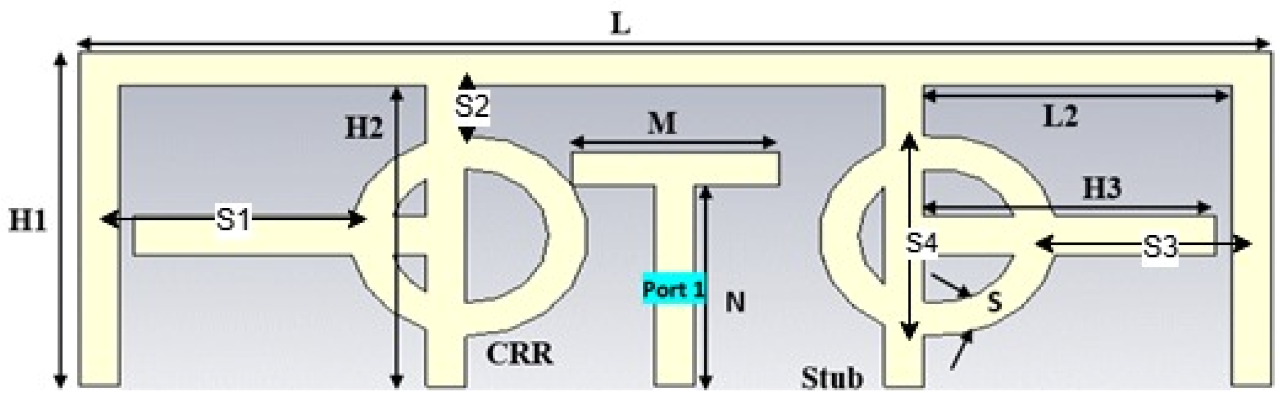
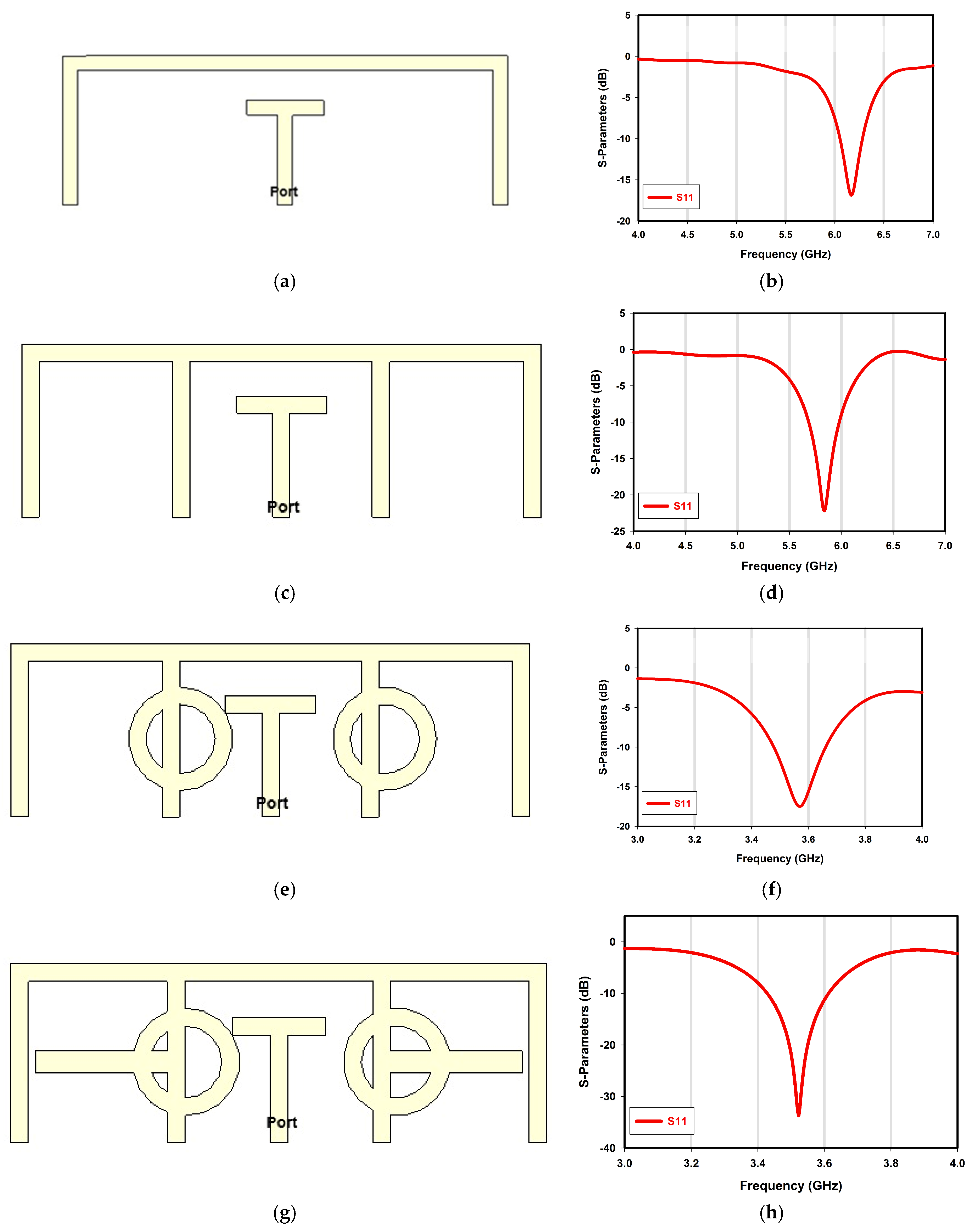
2. Antenna System Design
3. MIMO System Prototype
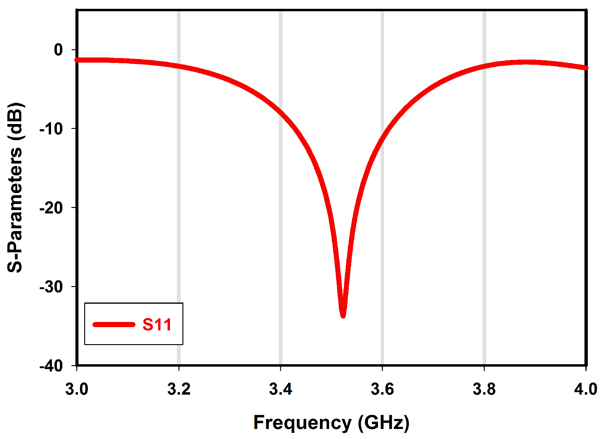
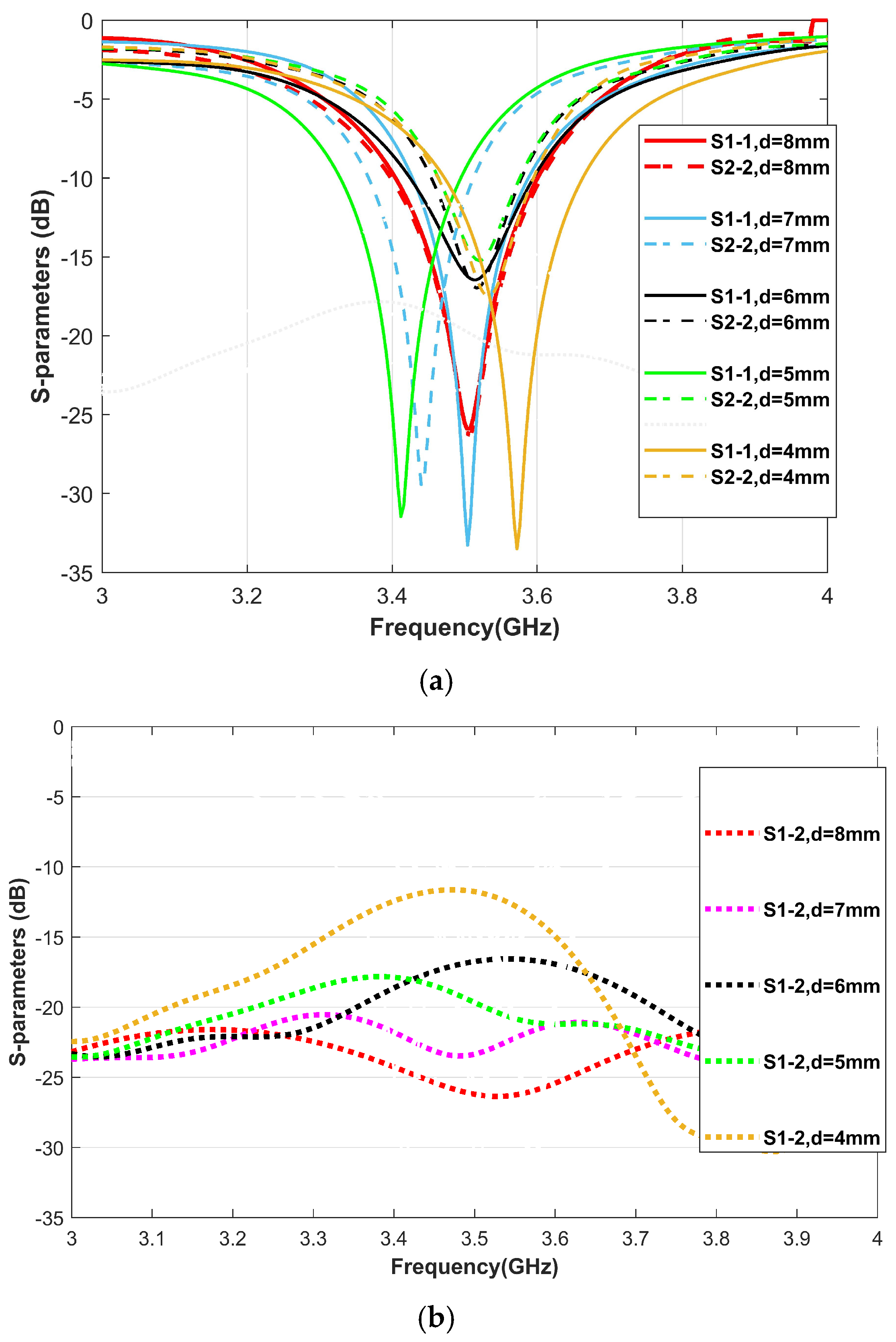
4. Results and Discussion
5. MIMO Antenna Performance Evaluation
6. Conclusions
Author Contributions
Funding
Data Availability Statement
Acknowledgments
Conflicts of Interest
References
- Wang, Y.; Li, J.; Huang, L.; Jing, Y.; Georgakopoulos, A.; Demestichas, P. 5G mobile: Spectrum broadening to higher-frequency bands to support high data rates. IEEE Veh. Technol. Mag. 2014, 9, 39–46. [Google Scholar] [CrossRef]
- Wong, K.; Chen, Y.; Li, W. Decoupled compact ultra-wideband MIMO antennas covering 3300∼6000 MHz for the fifth-generation mobile and 5GHz-WLAN operations in the future smartphone. Microw. Opt. Technol. Lett. 2018, 60, 2345–2351. [Google Scholar] [CrossRef]
- Li, R.; Mo, Z.; Sun, H.; Sun, X.; Du, G. A low-profile and high-isolated MIMO antenna for 5G mobile terminal. Micromachines 2020, 11, 360. [Google Scholar] [CrossRef] [PubMed]
- Ibrahim, S.K.; Singh, M.J.; Al-Bawri, S.S.; Ibrahim, H.H.; Islam, M.T.; Islam, M.S.; Alzamil, A.; Abdulkawi, W.M. Design, Challenges and Developments for 5G Massive MIMO Antenna Systems at Sub 6-GHz Band: A Review. Nanomaterials 2023, 13, 520. [Google Scholar] [CrossRef]
- Hazarika, A.; Rahmati, M. Towards an Evolved Immersive Experience: Exploring 5G- and Beyond-Enabled Ultra-Low-Latency Communications for Augmented and Virtual Reality. Sensors 2023, 23, 3682. [Google Scholar] [CrossRef] [PubMed]
- Ojaroudi Parchin, N.; Jahanbakhsh Basherlou, H.; Al-Yasir, Y.I.A.; Abdulkhaleq, A.M.; Patwary, M.; Abd-Alhameed, R.A. A New CPW-Fed Diversity Antenna for MIMO 5G Smartphones. Electronics 2020, 9, 261. [Google Scholar] [CrossRef]
- Elshirkasi, A.M.; Abdullah Al-Hadi, A.; Khan, R.; Akkaraekthalin, P.; Abdelmula, H.S.B.; Belghasem, A.M.; Jebril, A.H.; Soh, P.J. Numerical Analysis of Users’ Body Effects on a Fourteen-Element Dual-Band 5G MIMO Mobile Terminal Antenna. IEEE Access 2022, 10, 2083–2096. [Google Scholar] [CrossRef]
- Nej, S.; Ghosh, A.; Ahmad, S.; Kumar, J.; Ghaffar, A.; Hussein, M.I. Design and Characterization of 10-Elements MIMO Antenna with Improved Isolation and Radiation Characteristics for mm-Wave 5G Applications. IEEE Access 2022, 10, 125086–125101. [Google Scholar] [CrossRef]
- Gupta, A.; Kansal, A.; Chawla, P. Design of a wearable MIMO antenna deployed with an inverted U-shaped ground stub for diversity performance enhancement. Int. J. Microw. Wirel. Technol. 2021, 13, 76–86. [Google Scholar] [CrossRef]
- Jensen, M.A.; Wallace, J.W. A Review of Antennas and Propagation for MIMO Wireless Communications. IEEE Trans. Antennas Propag. 2004, 52, 2810–2824. [Google Scholar] [CrossRef]
- Kim, S.; Nam, S. A compact and wideband linear array antenna with low mutual coupling. IEEE Trans. Antennas Propag. 2019, 67, 5695–5699. [Google Scholar] [CrossRef]
- Khalid, M.; Iffat Naqvi, S.; Hussain, N.; Rahman, M.; Fawad; Mirjavadi, S.S.; Khan, M.J.; Amin, Y. 4-Port MIMO Antenna with Defected Ground Structure for 5G Millimeter Wave Applications. Electronics 2020, 9, 71. [Google Scholar] [CrossRef]
- Wong, K.L.; Lu, J.Y. 3.6-GHz 10-antenna array for mimo operation in the smartphone. Microw. Opt. Technol. Lett. 2015, 57, 1699–1704. [Google Scholar] [CrossRef]
- Kiani, S.H.; Altaf, A.; Abdullah, M.; Muhammad, F.; Shoaib, N.; Anjum, M.R.; Damaševičius, R.; Blažauskas, T. Eight element side edged framed MIMO antenna array for future 5G smart phones. Micromachines 2020, 11, 956. [Google Scholar] [CrossRef]
- Aljaafreh, S.S.; Altarawneh, B.; Alshamaileh, M.H.; Almajali, E.R.; Hussain, R.; Sharawi, M.S.; Xing, L.; Xu, Q. Ten Antenna Array Using a Small Footprint Capacitive-Coupled-Shorted Loop Antenna for 3.5 GHz 5G Smartphone Applications. IEEE Access 2021, 9, 33796–33810. [Google Scholar] [CrossRef]
- Cheng, Y.; Liu, H.; Sheng, B.Q.; Zhu, L. A compact 4-element MIMO antenna for terminal devices. Microw. Opt. Technol. Lett. 2020, 62, 2930–2937. [Google Scholar] [CrossRef]
- Xu, Z.; Deng, C. High-Isolated MIMO Antenna Design Based on Pattern Diversity for 5G Mobile Terminals. IEEE Antennas Wirel. Propag. Lett. 2020, 19, 467–471. [Google Scholar] [CrossRef]
- Elalaouy, O.; EL Ghzaoui, M.; Foshi, J. A high-isolated wideband two-port MIMO antenna for 5G millimeter-wave applications. Results Eng. 2024, 23, 102466. [Google Scholar] [CrossRef]
- Jiang, W.; Liu, B.; Cui, Y.; Hu, W. High-Isolation Eight-Element MIMO Array for 5G Smartphone Applications. IEEE Access 2019, 7, 34104–34112. [Google Scholar] [CrossRef]
- Li, M.; Jiang, L.; Yeung, K.L. A General and Systematic Method to Design Neutralization Lines for Isolation Enhancement in MIMO Antenna Arrays. IEEE Trans. Veh. Technol. 2020, 69, 6242–6253. [Google Scholar] [CrossRef]
- Saha, P.B.; Ghoshal, D.; Dash, R.K.; Roy, S. Neutralizing line based triple-band MIMO antenna with polarization diversity for WLAN/C/X band usage. Int. J. Electron. 2023, 110, 405–425. [Google Scholar] [CrossRef]
- Sun, Y.; Tian, M.; Cheng, G.S. Characteristic Mode-Based Neutralization Line Design for MIMO Antenna. Int. J. Antennas Propag. 2022, 2022, 9669114. [Google Scholar] [CrossRef]
- Moses, A.T.Z.; Moses, N. Compact self decoupled MIMO antenna pairs covering 3.4–3.6 GHz band for 5G handheld device applications. AEU—Int. J. Electron. Commun. 2021, 141, 153971. [Google Scholar] [CrossRef]
- Wong, K.-L.; Tsai, C.-Y.; Lu, J.-Y. Two Asymmetrically Mirrored Gap-Coupled Loop Antennas as a Compact Building Block for Eight-Antenna MIMO Array in the Future Smartphone. IEEE Trans. Antennas Propag. 2017, 65, 1765–1778. [Google Scholar] [CrossRef]
- Li, M.; Cheung, S. A Novel Calculation-Based Parasitic Decoupling Technique for Increasing Isolation in Multiple-Element MIMO Antenna Arrays. IEEE Trans. Veh. Technol. 2021, 70, 446–458. [Google Scholar] [CrossRef]
- Roy, S.; Chakraborty, U. Mutual Coupling Reduction in a Multi-band MIMO Antenna Using Meta-Inspired Decoupling Network. Wirel. Pers. Commun. 2020, 114, 3231–3246. [Google Scholar] [CrossRef]
- Singh, H.V.; Tripathi, S.; Mohan, A. Closely-coupled MIMO antenna with high wideband isolation using decoupling circuit. AEU—Int. J. Electron. Commun. 2021, 138, 153833. [Google Scholar] [CrossRef]
- Sufian, M.A.; Hussain, N.; Askari, H.; Park, S.G.; Shin, K.S.; Kim, N. Isolation Enhancement of a Metasurface-Based MIMO Antenna Using Slots and Shorting Pins. IEEE Access 2021, 9, 73533–73543. [Google Scholar] [CrossRef]
- Altaf, A.; Iqbal, A.; Smida, A.; Smida, J.; Althuwayb, A.A.; Hassan Kiani, S.; Alibakhshikenari, M.; Falcone, F.; Limiti, E. Isolation Improvement in UWB-MIMO Antenna System Using Slotted Stub. Electronics 2020, 9, 1582. [Google Scholar] [CrossRef]
- Abubakar, H.S.; Zhao, Z.; Wang, B.; Kiani, S.H.; Parchin, N.O.; Hakim, B. Eight-Port Modified E-Slot MIMO Antenna Array with Enhanced Isolation for 5G Mobile Phone. Electronics 2023, 12, 316. [Google Scholar] [CrossRef]
- Yuan, X.-T.; He, W.; Hong, K.-D.; Han, C.-Z.; Chen, Z.; Yuan, T. Ultra-Wideband MIMO Antenna System with High Element-Isolation for 5G Smartphone Application. IEEE Access 2020, 8, 56281–56289. [Google Scholar] [CrossRef]
- Zhang, H.H.; Yu, G.G.; Liu, X.Z.; Cheng, G.S.; Xu, Y.X.; Liu, Y.; Shi, G.M. Low-SAR MIMO Antenna Array Design Using Characteristic Modes for 5G Mobile Phones. IEEE Trans. Antennas Propag. 2022, 70, 3052–3057. [Google Scholar] [CrossRef]
- Armghan, A.; Patel, S.K.; Lavadiya, S.; Qamar, S.; Alsharari, M.; Daher, M.G.; Althuwayb, A.A.; Alenezi, F.; Aliqab, K. Design and Fabrication of Compact, Multiband, High Gain, High Isolation, Metamaterial-Based MIMO Antennas for Wireless Communication Systems. Micromachines 2023, 14, 357. [Google Scholar] [CrossRef] [PubMed]
- Ameen, M.; Chaudhary, R.K. Isolation Enhancement of Metamaterial-Inspired Two-Port MIMO Antenna Using Hybrid Techniques. IEEE Trans. Circuits Syst. II Express Briefs 2023, 70, 1966–1970. [Google Scholar] [CrossRef]
- Puri, V.; Singh, H.S. Design of an isolation improved MIMO antenna using metasurface based absorber for wireless applications. Optik 2022, 259, 168963. [Google Scholar] [CrossRef]
- Sengar, S.; Malik, P.K.; Chandra Srivastava, P.; Srivastava, K.; Gehlot, A. Performance Analysis of MIMO Antenna Design with High Isolation Techniques for 5 G Wireless Systems. Int. J. Antennas Propag. 2023, 2023, 1566430. [Google Scholar] [CrossRef]
- Singh, H.V.; Prasad, D.V.S.; Tripathi, S. Self-isolated MIMO antenna using mixed coupling by close coupling technique. Sci. Rep. 2023, 13, 5636. [Google Scholar] [CrossRef]
- Muhsin, M.Y.; Salim, A.J.; Ali, J.K. A Compact Self-Isolated MIMO Antenna System for 5G Mobile Terminals. Comput. Syst. Sci. Eng. 2022, 42, 919–934. [Google Scholar] [CrossRef]
- Bait-Suwailam, M.M.; Siddiqui, O.F.; Ramahi, O.M. Mutual Coupling Reduction Between Microstrip Patch Antennas Using Slotted-Complementary Split-Ring Resonators. IEEE Antennas Wirel. Propag. Lett. 2010, 9, 876–878. [Google Scholar] [CrossRef]
- Bait-Suwailam, M.M.; Boybay, M.S.; Ramahi, O.M. Electromagnetic Coupling Reduction in High-Profile Monopole Antennas Using Single-Negative Magnetic Metamaterials for MIMO Applications. IEEE Trans. Antennas Propag. 2010, 58, 2894–2902. [Google Scholar] [CrossRef]
- Mengozzi, M.; Gibiino, G.P.; Angelotti, A.M.; Florian, C.; Santarelli, A. Beam-Dependent Active Array Linearization by Global Feature-Based Machine Learning. IEEE Microw. Wirel. Technol. Lett. 2023, 33, 895–898. [Google Scholar] [CrossRef]
- Matta, L.; Sharma, B.; Sharma, M. A review on bandwidth enhancement techniques and band-notched characteristics of MIMO-ultra wide band antennas. Wirel. Netw. 2024, 30, 1339–1382. [Google Scholar] [CrossRef]
- Dhasarathan, V.; Nguyen, T.K.; Sharma, M.; Patel, S.K.; Mittal, S.K.; Pandian, M.T. Design, analysis and characterization of four port multiple-input-multiple-output UWB-X band antenna with band rejection ability for wireless network applications. Wirel. Netw. 2020, 26, 4287–4302. [Google Scholar] [CrossRef]
- Sharma, P.; Tiwari, R.N.; Singh, P.; Kumar, P.; Kanaujia, B.K. MIMO Antennas: Design Approaches, Techniques and Applications. Sensors 2022, 22, 7813. [Google Scholar] [CrossRef] [PubMed]
- Khan, A.; Wakeel, A.; Qu, L.; Zahid, Z. Dual-band 8 × 8 MIMO antenna with enhanced isolation and efficiency for 5G smartphone applications. AEU—Int. J. Electron. Commun. 2023, 163, 154600. [Google Scholar] [CrossRef]
- Yu, H.; Shang, X.; Xue, Q.; Ding, H.; Wang, J.; Lv, W.; Luo, Y. Twelve-Element MIMO Wideband Antenna Array Operating at 3.3 GHz for 5G Smartphone Applications. Electronics 2024, 13, 3585. [Google Scholar] [CrossRef]
- Gautam, A.K.; Yadav, S.; Rambabu, K. Design of ultra-compact UWB antenna with band-notched characteristics for MIMO applications. IET Microw. Antennas Propag. 2018, 12, 1895–1900. [Google Scholar]
- Rubani, Q.; Gupta, S.H.; Rajawat, A. A compact MIMO antenna for WBAN operating at Terahertz frequency. Optik 2020, 207, 164447. [Google Scholar]
- Rekha, V.S.D.; Pardhasaradhi, P.; Madhav, B.T.P.; Devi, Y.U. Dual Band Notched Orthogonal 4-Element MIMO Antenna with Isolation for UWB Applications. IEEE Access 2020, 8, 145871–145880. [Google Scholar]
- Chen, Z.; Liu, Y.; Yuan, T.; Wong, H. A Miniaturized MIMO Antenna with Dual-Band for 5G Smartphone Application. IEEE Open J. Antennas Propag. 2023, 4, 111–117. [Google Scholar]
- Ghawbar, F.; Sukor, J.A.; Majid, H.A.; Ghafar, A.S.A.; Saparudin, F.A.; Esmail, B.A.F.; Almohammedi, A.A.; Esmail, A.G. High Isolated 10-MIMO Antenna Elements for 5G Mobile Applications. Int. J. Integr. Eng. 2023, 15, 265–276. [Google Scholar]


| Parameter | Value (mm) |
|---|---|
| L | 15 |
| L2 | 4.3 |
| H1 | 5 |
| H2 | 4.4 |
| H3 | 3.9 |
| M | 2.6 |
| N | 3 |
| S | 0.5 |
| S1 | 2.92 |
| S2 | 0.85 |
| S3 | 2.2 |
| S4 | 2.98 |
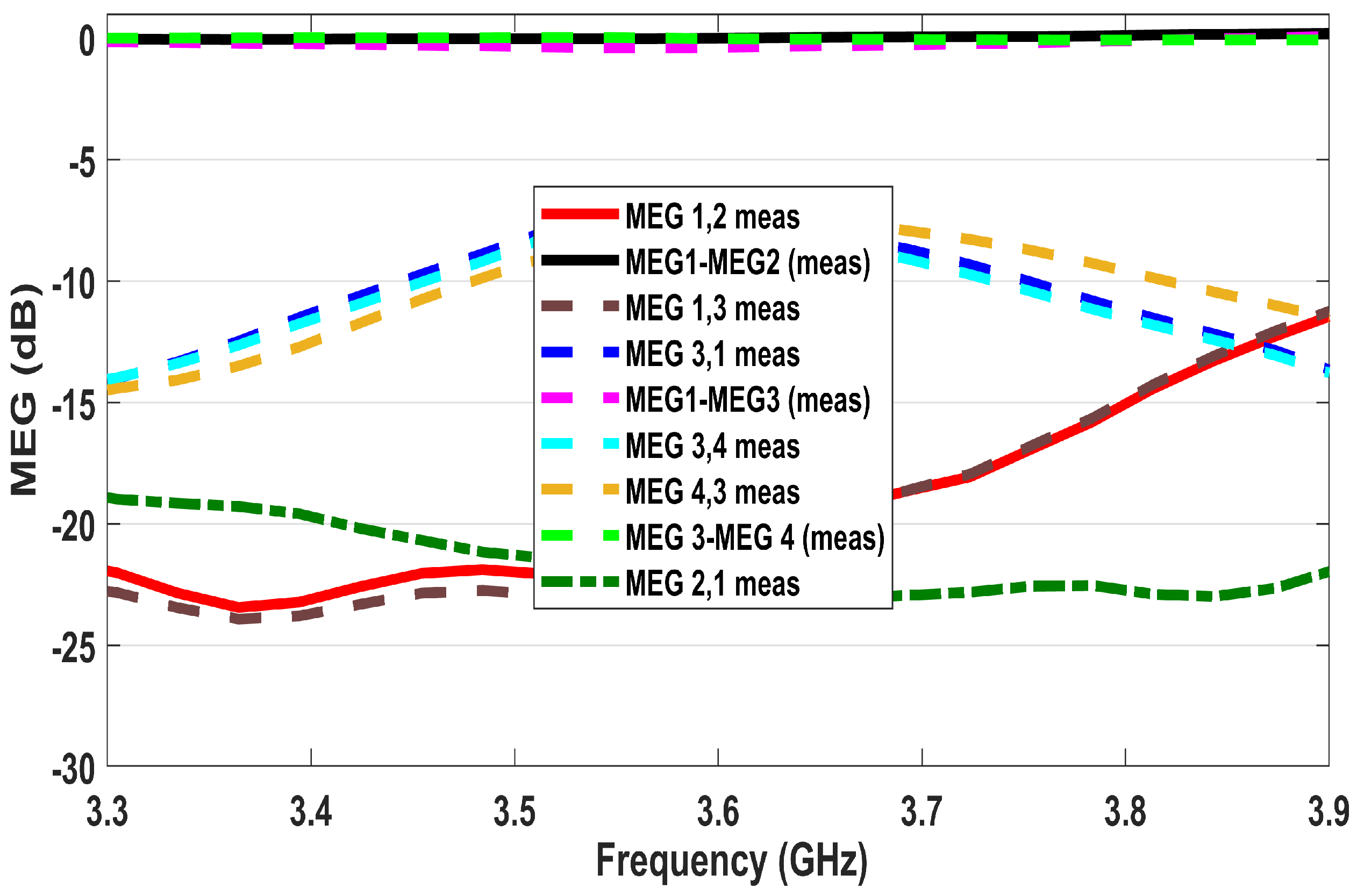
| MEGi,j | K = MEGi,j − MEGj,i (dB) | MEGi | MEGj,i | K = MEGi,j − MEGj,i (dB) | MEGj |
|---|---|---|---|---|---|
| MEG1,2 | −6.0531 | MEG4,5 | −6.1569 | ||
| MEG2,1 | −6.1717 | MEG5,4 | −6.1025 | ||
| MEG1-2 | 0.0131 | MEG1/MEG2 = 0.980783 | MEG4-5 | −0.0544 | MEG4/MEG5 = 1.008914 |
| MEG1,3 | −6.1532 | MEG4,6 | −6.0793 | ||
| MEG3,1 | −6.0831 | MEG6,4 | −6.1511 | ||
| MEG1-3 | −0.0701 | MEG1/MEG3 = 1.011524 | MEG4-6 | 0.0161 | MEG4/MEG6 = 0.988327 |
| EMG1,4 | −6.0444 | MEG11,4 | −6.0531 | ||
| MEG4,1 | −6.0284 | MEG4,11 | −6.1717 | ||
| MEG1-4 | −0.0155 | MEG1/MEG4 = 1.002654 | MEG4-11 | 0.0131 | MEG4/MEG11 = 0.980783 |
| EMG1,7 | −6.1586 | MEG6,7 | −6.1532 | ||
| MEG7,1 | −6.1717 | MEG7,6 | −6.0831 | ||
| MEG1-7 | 0.0131 | MEG1/MEG7 = 0.997877 | MEG6-7 | −0.0701 | MEG6/MEG7 = 1.011524 |
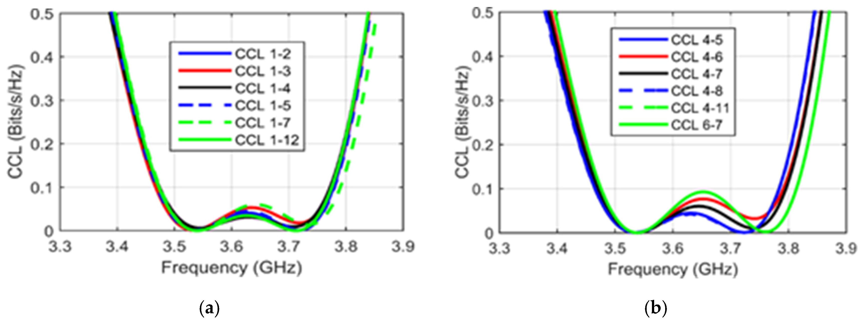
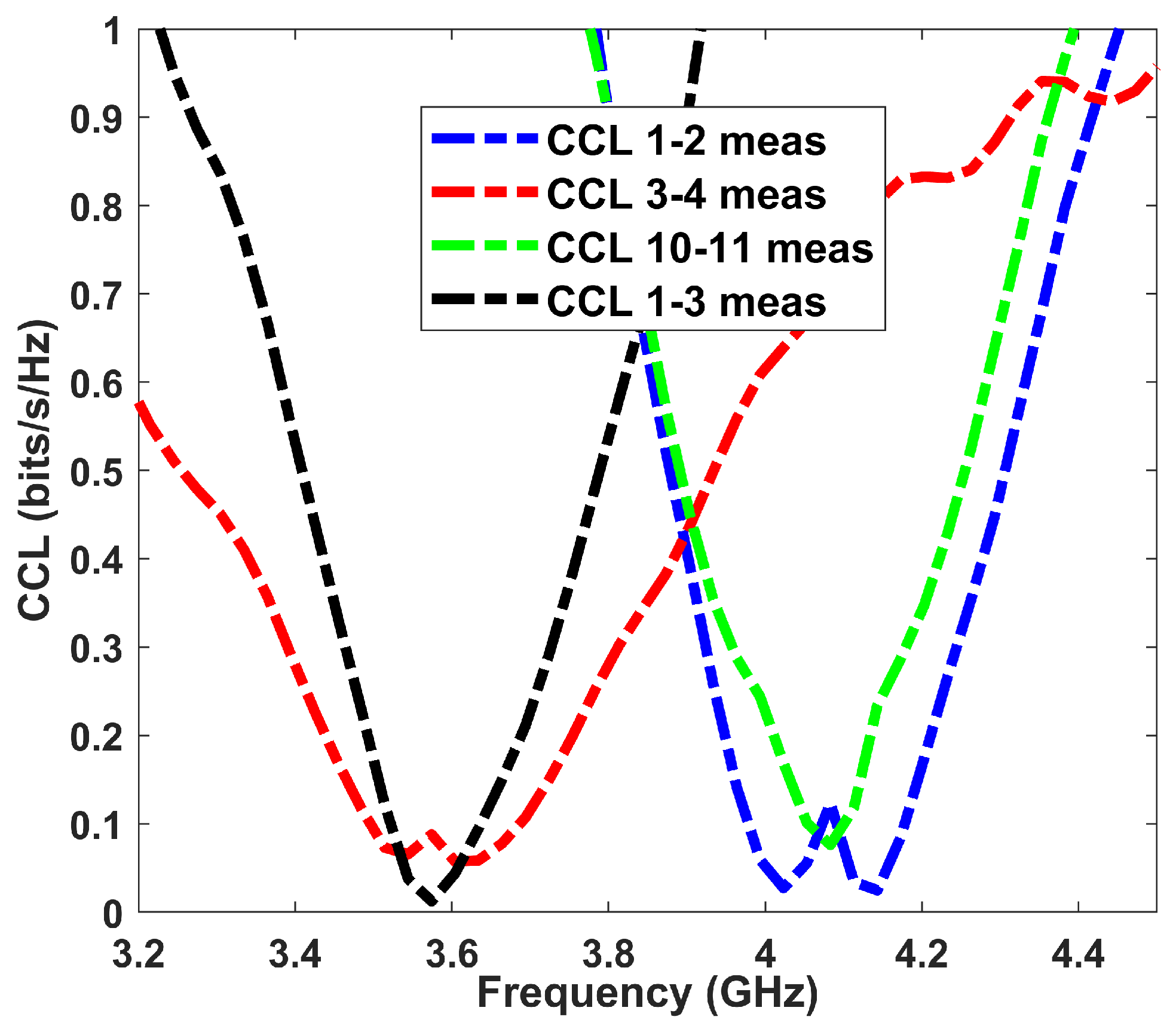
| MIMO Antenna Elements | CCL (Bits/s/Hz) | MIMO Antenna Elements | CCL (Bits/s/Hz) |
|---|---|---|---|
| CCL1,2 | 0.0341 | CCL4,6 | 0.0357 |
| CCL1,3 | 0.0237 | CCL4,7 | 0.0300 |
| CCL1,4 | 0.0395 | CCL4,8 | 0.0227 |
| CCL1,5 | 0.0268 | CCL4,11 | −1.9834 |
| CCL1,7 | 0.0341 | CCL6,7 | 0.0357 |
| CCL1,12 | 0.0319 | CCL9,10 | 0.0217 |
| Ref. | Ant Size (mm2) (Single) | MIMO Order | Isolation (dB) | d (mm) | ECC (dB) | TARC (dB) | DG (dB) | CCL (dB) |
|---|---|---|---|---|---|---|---|---|
| [13] | 3 × 8 | 10 | <−12 | 15 | <0.1 | - | - | - |
| [14] | 16 × 7 | 8 | <−12 | 22 | <0.1 | - | - | - |
| [19] | 12.5 × 4.9 | 8 | <−14 | 17 | <0.15 | - | - | - |
| [24] | 10 × 7 | 8 | <−12 | 15 | <0.1 | - | - | - |
| [23] | 30 × 5.2 | 4 | <−16.5 | 17 | <0.03 | <−11 | >9.995 | 0.35 |
| [32] | 23.2 × 5.6 | 8 | <−15 | 13.2 | <0.08 | - | - | - |
| [45] | 11 × 4.5 | 8 | <−20 | 17 | <0.11 | <−10 | 9.98 | - |
| [46] | 12.95 × 6 | 12 | <−12 | 12.5 | <−0.065 | - | 9.6 | - |
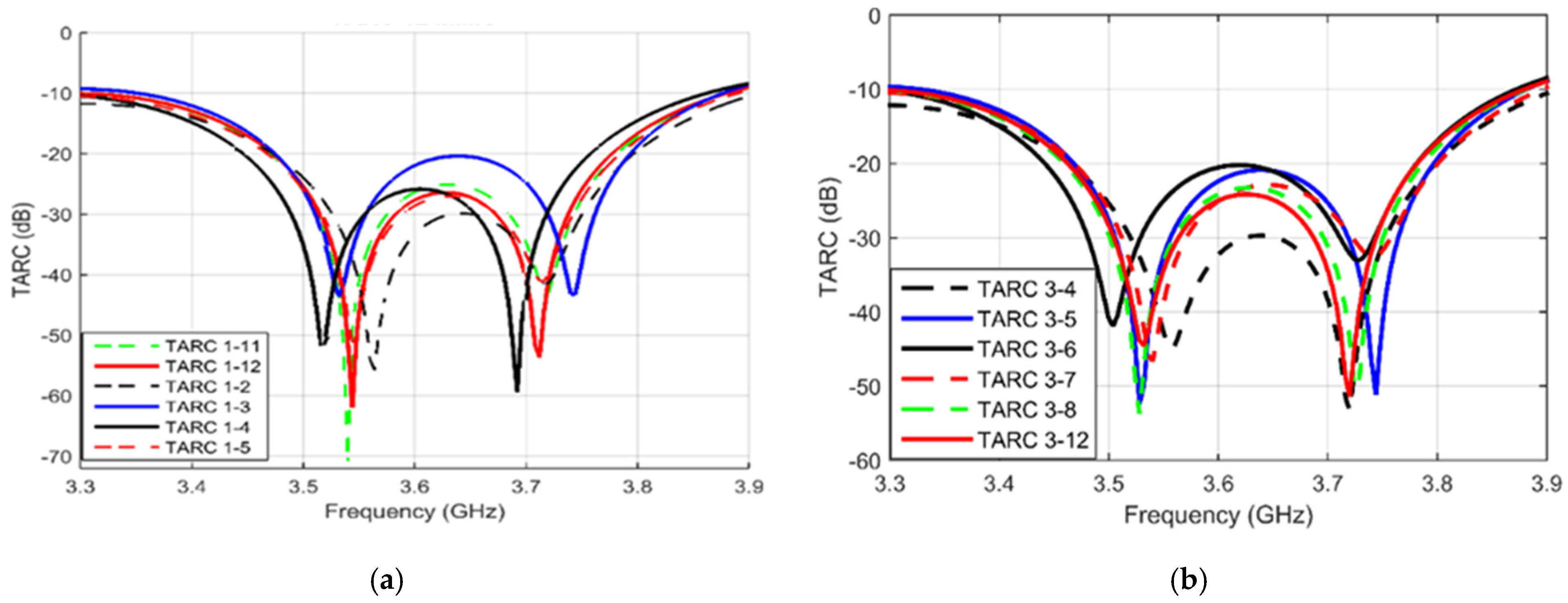
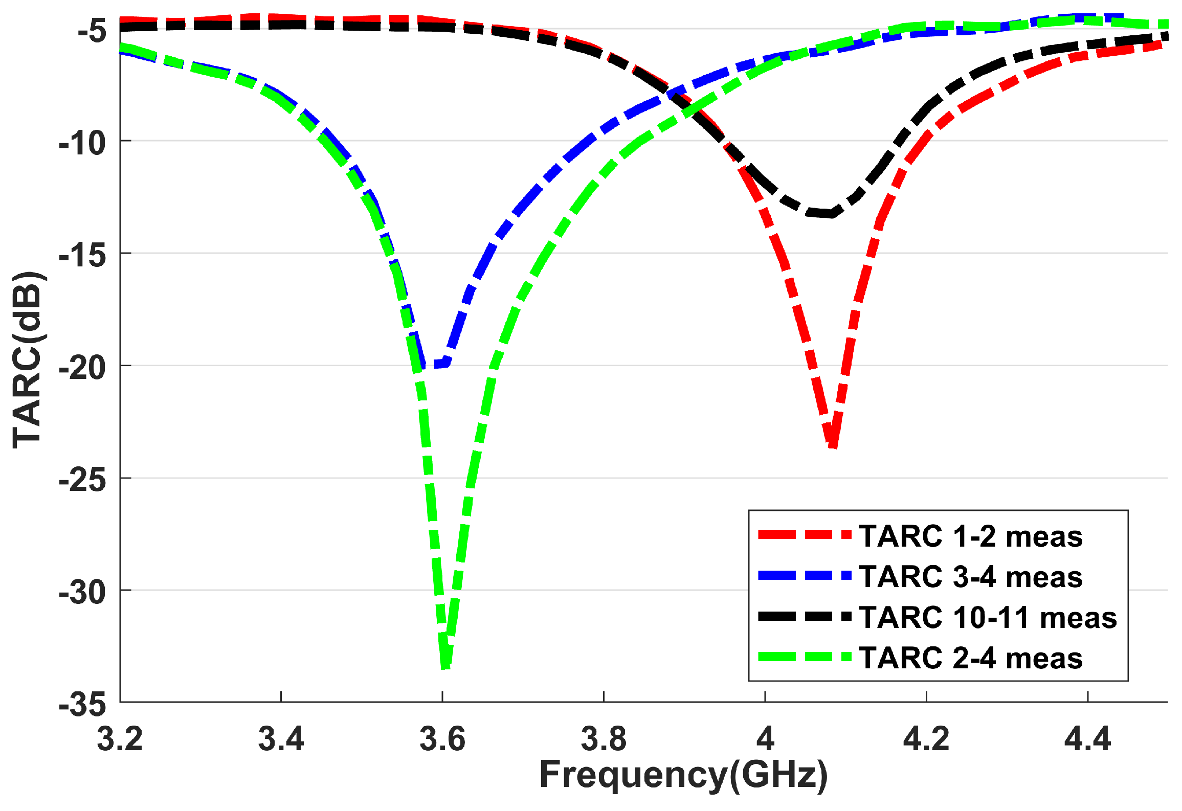
| Pro | 15 × 5 | 12 | <−19 | 8 | <0.006 | <−11 | >9.97 | <0.08 |
Disclaimer/Publisher’s Note: The statements, opinions and data contained in all publications are solely those of the individual author(s) and contributor(s) and not of MDPI and/or the editor(s). MDPI and/or the editor(s) disclaim responsibility for any injury to people or property resulting from any ideas, methods, instructions or products referred to in the content. |
© 2025 by the authors. Licensee MDPI, Basel, Switzerland. This article is an open access article distributed under the terms and conditions of the Creative Commons Attribution (CC BY) license (https://creativecommons.org/licenses/by/4.0/).
Share and Cite
Ghawbar, F.; Sukur, J.A.; Majid, H.A.; Bait-Suwailam, M.M.; Al-Lawati, H.; Amer, A.A.G.; Saparudin, F.A.; Ghafar, A.S.A. Highly Self-Isolated 12-MIMO Antenna Elements for 5G Mobile Applications. Electronics 2025, 14, 1424. https://doi.org/10.3390/electronics14071424
Ghawbar F, Sukur JA, Majid HA, Bait-Suwailam MM, Al-Lawati H, Amer AAG, Saparudin FA, Ghafar ASA. Highly Self-Isolated 12-MIMO Antenna Elements for 5G Mobile Applications. Electronics. 2025; 14(7):1424. https://doi.org/10.3390/electronics14071424
Chicago/Turabian StyleGhawbar, Fayad, Jumadi A. Sukur, Huda A. Majid, Mohammed M. Bait-Suwailam, Hassan Al-Lawati, Abdulrahman A. G. Amer, Faiz A. Saparudin, and Aimi S. A. Ghafar. 2025. "Highly Self-Isolated 12-MIMO Antenna Elements for 5G Mobile Applications" Electronics 14, no. 7: 1424. https://doi.org/10.3390/electronics14071424
APA StyleGhawbar, F., Sukur, J. A., Majid, H. A., Bait-Suwailam, M. M., Al-Lawati, H., Amer, A. A. G., Saparudin, F. A., & Ghafar, A. S. A. (2025). Highly Self-Isolated 12-MIMO Antenna Elements for 5G Mobile Applications. Electronics, 14(7), 1424. https://doi.org/10.3390/electronics14071424