Article

Tele Haptic Handshake Using Distributed Pressure Presentation Device and Mutual Interaction Pressure Model

1
Department of Mechanical Engineering, Kobe University, Hyogo 657-8501, Japan
2
Haptics Laboratory, Faculty of Fiber Science and Engineering, Kyoto Institute of Technology, Kyoto 606-8585, Japan
*
Author to whom correspondence should be addressed.
These authors contributed equally to this work.
Electronics 2025, 14(3), 537; https://doi.org/10.3390/electronics14030537
Submission received: 29 December 2024 / Revised: 25 January 2025 / Accepted: 27 January 2025 / Published: 28 January 2025
(This article belongs to the Special Issue Haptic Systems and the Tactile Internet: Design and Applications)

Abstract

:
This study investigates the mutual interaction between self- and partner-induced actions in determining pressure distribution during a handshake and proposes a tele haptic handshake system based on these findings. To achieve this, experiments were conducted to examine how pressure distribution in face-to-face handshakes is influenced by mutual actions. Based on the experimental results, an interaction force model was developed to calculate stimulus intensities, incorporating region-specific weights for different parts of the hand. Additionally, a tele haptic handshake system was designed, integrating flex sensors to measure finger joint angles and a distributed haptic stimulus presentation device to provide tactile feedback. While this study lays the foundation for understanding the dynamics of handshake interactions and their application in remote environments, further validation of the system’s effectiveness in replicating real-world handshake experiences remains a subject for future work.

1. Introduction

1.1. Background

Tools for communication in remote and virtual environments, such as video chats and metaverse platforms in VR spaces, have become increasingly prevalent. These tools are not only used for everyday communication but have also been adopted in domains like healthcare, welfare, education, and tourism, which traditionally relied on face-to-face interactions. By enabling communication without the constraints of physical distance, they hold the potential to address issues faced by industries suffering from a shortage of skilled personnel.
However, current communication tools have limitations, particularly in the range of information that can be transmitted. In face-to-face interactions, humans exchange not only verbal information but also nonverbal cues such as facial expressions, body movements, touch, odors, interpersonal distance, and gaze. These nonverbal cues play critical roles in expressing emotions and attitudes, shaping impressions, and interpreting the emotions of others. They are often used alongside verbal communication [1,2,3]. In contrast, remote and virtual environments lack these nonverbal cues due to restricted visual information from cameras and the absence of olfactory and tactile feedback, leading to a decline in communication quality compared to face-to-face interactions.
To address these challenges, research into devices capable of transmitting haptic information, which is closely related to nonverbal communication, has gained significant attention. These studies have proposed various methods to replicate social touches such as tapping, hugging, massaging, and stroking [3,4,5,6]. These proposed methods have demonstrated improvements in trust, social presence, and emotional expression in remote and virtual communication, indicating their potential to enhance the overall quality of communication.
This study focuses on handshakes, a fundamental form of social touch among humans. Unlike unidirectional social touches, such as stroking, where one party acts upon the other, handshakes involve mutual interaction, enabling simultaneous self-expression and understanding of the other party. This mutual adjustment of actions can significantly enhance the communicative effects. Furthermore, unlike other interactive social touches such as hugs, which are often limited to close relationships, handshakes are widely used in diverse contexts, including greetings among friends, business settings, and sports. Therefore, enabling handshakes in remote and virtual environments is expected to be applicable across various scenarios, regardless of the relationship between participants. Additionally, as handshakes are globally recognized as a form of tactile interaction, they are expected to facilitate communication across different cultures [7].
Applications of a remote handshake system span multiple fields. In professional settings, such as international business negotiations or virtual job interviews, a remote handshake could serve as a symbolic and tactile substitute for establishing rapport and trust. In the context of virtual reality and the metaverse, remote handshakes could significantly improve the realism and social presence of interactions, particularly in virtual collaboration, training, or social networking platforms.

1.2. Related Works

Several approaches have been proposed to achieve handshakes in remote and virtual environments using robotic hands. Vigni et al. applied a controller that integrates both active and passive actions, similar to humans, to improve the quality of handshakes [8]. Nakanishi et al. developed a robotic hand that replicates human hand temperature, softness, and grip strength [9]. They reported that handshakes mediated by this robotic hand during video chats created a more favorable impression of the remote partner. Ammi et al. implemented handshake functionality in robots to enhance emotional expressiveness [10]. Their results indicated that tactile feedback during handshakes, combined with facial expressions, made it easier for humans to identify the robot’s emotions compared to facial expressions alone. Faisal et al. developed a device capable of replicating gripping and shaking motions, demonstrating that human personality traits can be conveyed through remote handshakes [11].
While these studies successfully utilized robotic hands to replicate handshakes, they have notable limitations. Robotic hands tend to be large and stationary, posing challenges in terms of installation and space constraints. As a result, these approaches are less feasible for home environments, which are the primary use cases for communication tools. In VR settings, robotic hands can restrict user mobility due to limited actuation ranges, further diminishing their practicality.
Other methods have explored wearable haptic devices for tactile feedback. For example, devices providing force feedback to finger flexion have been proposed [12,13,14]. Although some of these devices are commercially available, they are often costly, limiting their practicality. Vibratory stimulation devices, which use mechanical vibrations to provide tactile feedback to the skin, have also been developed [15,16,17,18]. These devices are lightweight, compact, and cost-effective, offering advantages in wearability. However, the tactile information they provide is limited to vibrations, which may not fully replicate the forces experienced in real-world interactions.
Additionally, alternative approaches have been proposed. Nagano et al. developed a skin suction device that uses air tubes to apply suction pressure to the fingertips, creating the illusion of pressure [19]. Abad et al. developed a pin-based device capable of providing tactile feedback to multiple fingers using five actuators [20]. Yem et al. designed an electrical stimulation device that delivers stimuli to the fingertips, creating an illusion of pressure [21]. These methods offer high spatial resolution and precise control of tactile feedback positions but face challenges such as limited maximum tactile intensity.
Finally, pressure-based feedback devices using soft materials have been proposed. Yamaguchi et al. developed a device using a bag-type actuator that expands with the evaporation of a low-boiling-point liquid to provide pressure [22]. Yarosh et al. created a device that uses shape-memory alloys embedded in a band to squeeze the palm, providing pressure feedback [23]. While these approaches enable pressure simulation during handshakes and can replicate thermal sensations, they lack the ability for users to adjust handshake intensity freely. As handshake intensity is associated with personality traits [11,24] and emotions [25], developing a device and control model that allows users to freely express these factors through handshake intensity is crucial.
1.3. Objective

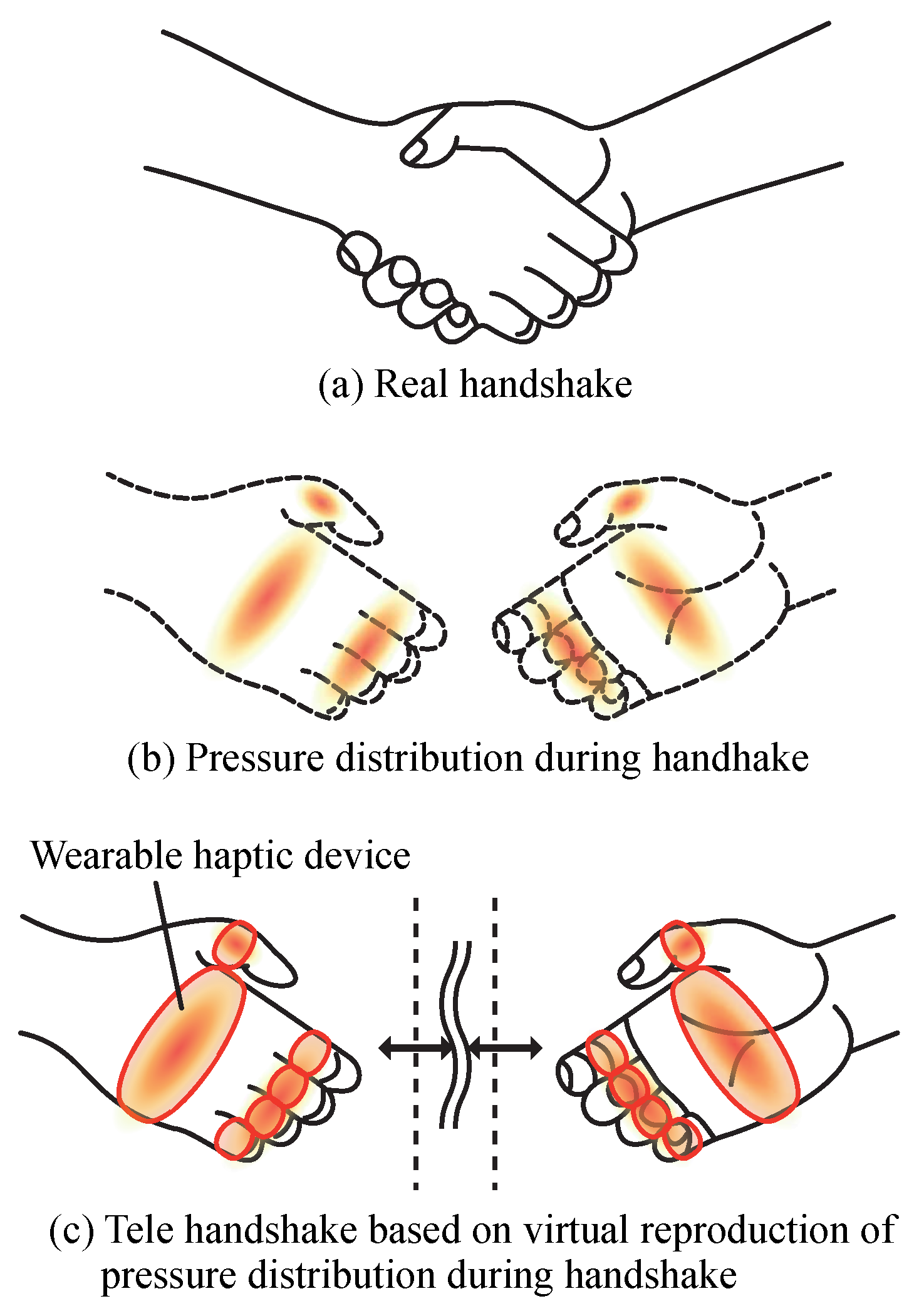
The objective of this study is to experimentally investigate whether the partner’s and one’s own actions interactively act on the respective pressure distributions in a handshake, and to use the results to develop a tactile transmission system for remote handshaking as shown in Figure 1. The system consists of a device that can measure finger flexion and a device that provides distributed tactile stimulation during handshaking. The basic configuration of the system has already been proposed by us in [26]. This study expands on that work by experimenting with multiple measurement experiments to determine the parameters that the system contains. Furthermore, we will develop an interaction pressure model to control the stimulus intensity based on the relationship between the finger flexion data and the weights of the stimulus sites.
The novelty and contributions of this study are follows:
  • Developed a haptic device capable of presenting spatially distributed tactile information based on handshake measurements.
  • Integrated the haptic device with sensors into a complete tactile transmission system for remote handshakes.
  • Proposed an interaction force distribution model that represents mutual interaction during handshakes.
  • Constructed the interaction model based on experimental data collected in handshake scenarios.

2. Distributed Haptic Information Transmission System for Mutual Communication

2.1. System Configuration

In face-to-face handshakes, pressure stimuli are distributed across the hand, including the fingers and palm, depending on the grip strength of both parties. In a remote environment, however, there is no direct physical contact with the other party. In this study, we construct a system that presents distributed tactile sensations in response to mutual handshaking movements between remotely located persons.
In the remote environment, it is not possible to measure the grip strength in an actual handshake. Therefore, we used a reasonable hypothesis that joint motion is related to grip strength and use finger joint angles as a proxy for grip strength. A quantitative and detailed investigation of the relationship between joint motion and grip force is a future developmental issue newly opened up by this study, which will lead to an improvement in the reproducibility of the system. The system consists of two main components: a finger joint angle measurement device and a distributed haptic pressure presentation device. The finger joint angle measurement device collects motion data from each participant, while the haptic stimulus presentation device applies distributed pressure stimuli to simulate a natural handshake experience. These components work together to present the pressure stimuli P cmd to be presented to itself (the subject side) based on the relationship between the finger joint angles of the subject side θ S and those of the object side θ O , as shown in Equation (1). The basic hardware configuration of the transmission system to be constructed is same in [26]. However, the formulation required for the detailed operation and the measurement experiments necessary for it are newly conducted in this study.
P cmd = f ( θ S , θ O ) .
In addition, in order to operate the system, the relationship between the bending sensor value R and the finger joint angle θ , as shown in Equation (2), needs be obtained. It is also necessary to obtain the relationship between the target presentation pressure P cmd and the motor rotation angle ϕ . These model equations are explained in detail in the following sections.
θ = g 1 ( R ) ,
ϕ = g 2 ( P cmd ) .

2.2. Finger Joint Angle Measurement Device

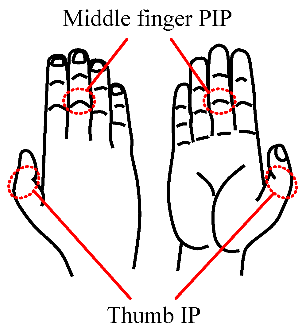
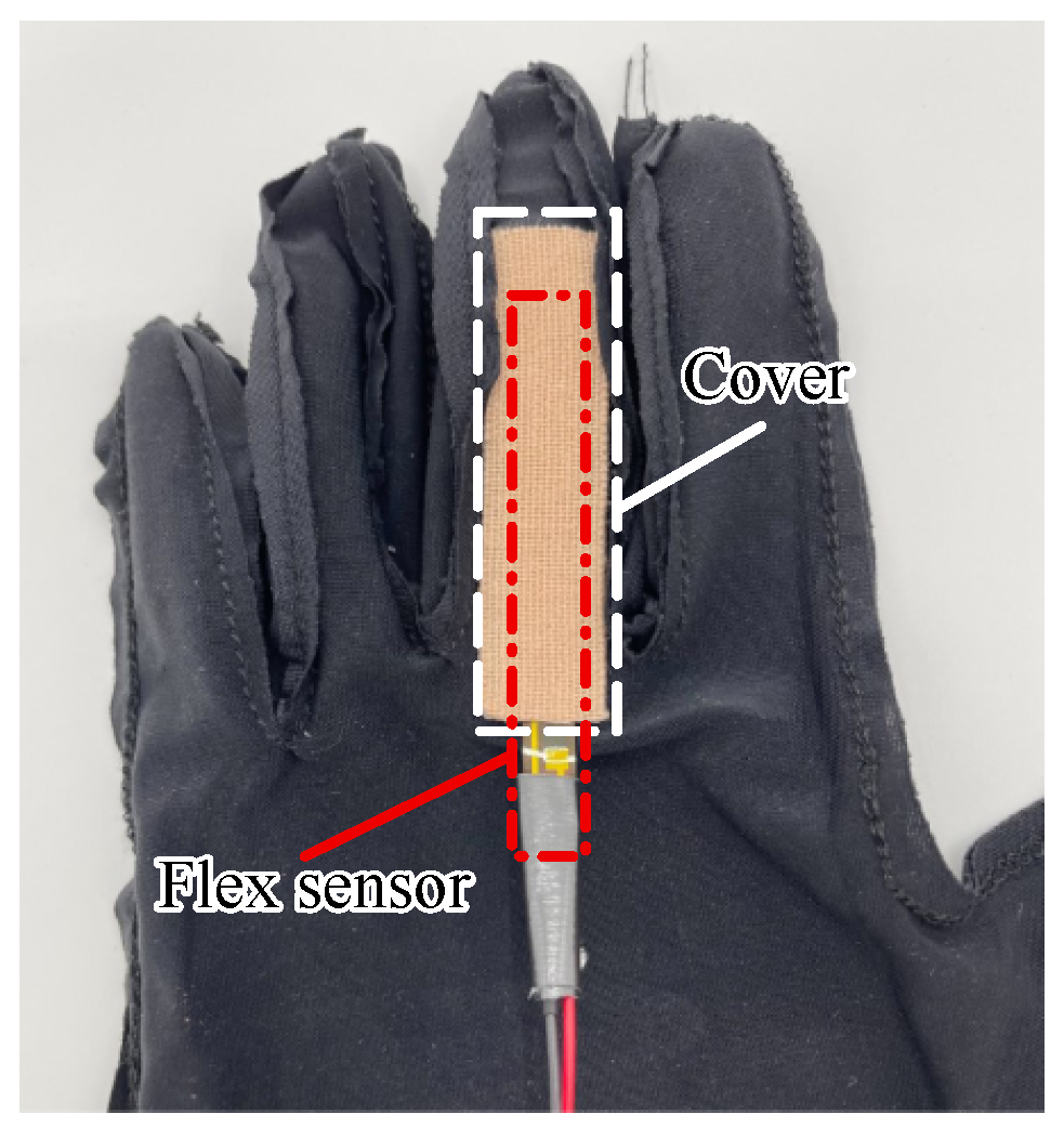
To measure finger joint angles, a flex sensor (ALPHA-MB060-N-221-A02, Taiwan Alpha Electronic Co., Ltd., Taoyuan, Taiwan) was employed due to its balance of cost, accuracy, and weight. The measurement points, shown in Figure 2, include the thumb’s interphalangeal joint (IP) and the middle finger’s proximal interphalangeal joint (PIP). These points were chosen as representative locations based on the known coupling of DIP, PIP, and MCP joint movements during simple flexion [27]. The flex sensor is mounted on a glove by inserting it into a pocket, as illustrated in Figure 3.
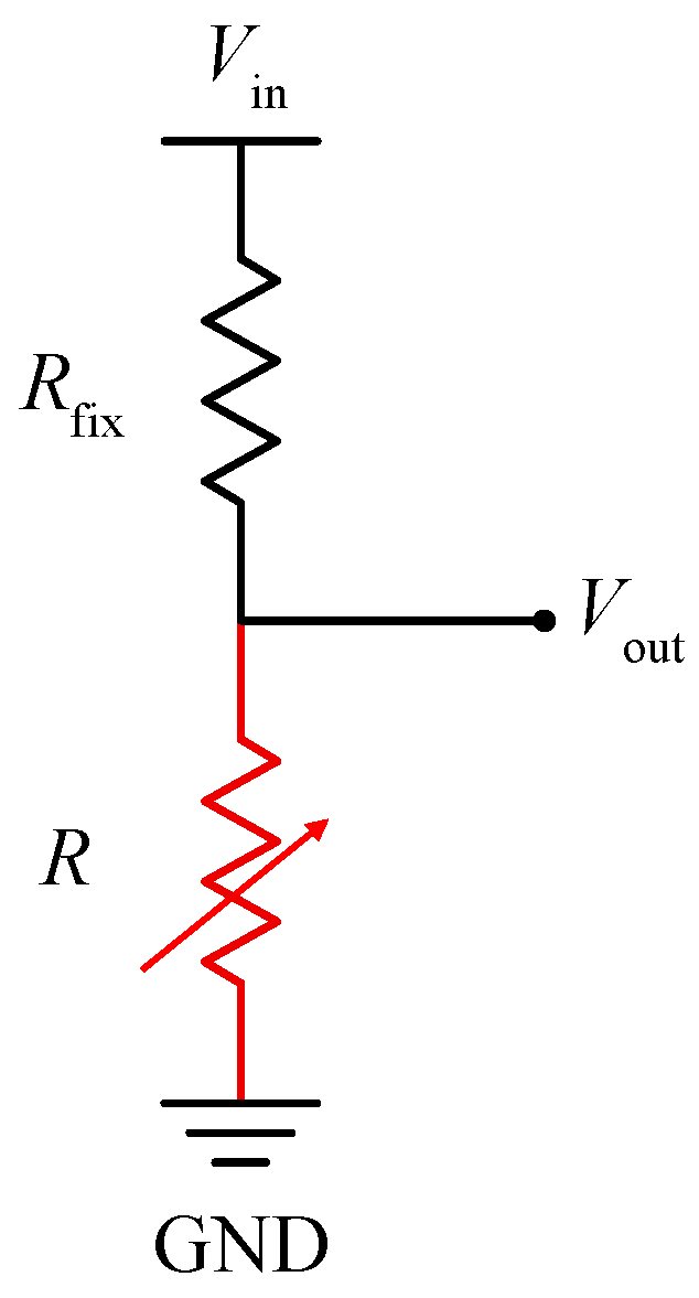
The flex sensor operates as a variable resistor whose resistance changes with the bending angle. Using the circuit in Figure 4, the output voltage V out is measured using an A/D converter (AIO-121602LN-USB, Contec Co., Ltd., Osaka, Japan). Input voltage V in is 5 V and the fixed resistance R fix is 22 Ω. The resistance R is then calculated using Equation (4). The calculated R is treated as a bending sensor value related to the finger joint angle.
R = V out V in V out × R fix .

2.3. Relationship Between Bending Sensor and Finger Joint Angle

In this section, the relationship between the bending sensor value R and the finger joint angle θ , which is simply expressed by Equation (2), is investigated. Flexion angle measurements using a flex sensor may vary due to differences in hand size and sensor attachment conditions. To address these variations, experiments were conducted to investigate the relationship between actual flexion angles and flex sensor values, and a calibration model was developed. Six participants (five males and one female) participated in the experiment.

2.3.1. Experimental Apparatus

The experimental apparatus included the constructed finger joint angle measurement device and a goniometer (SPR-627, SAKAIMedical Co., Ltd., Osaka, Japan), which can directly measure finger joint angles, as shown in Figure 5.

2.3.2. Experimental Procedure

The procedure was as follows:
  • Attach the finger joint angle measurement device and place the goniometer on the interphalangeal joint of the thumb.
  • Flex the thumb to angles of 0°, 30°, 50°, 70°, and 90° as indicated by the goniometer, and record the corresponding flex sensor values.
  • Repeat the measurements for the proximal interphalangeal joint of the middle finger.
  • Repeat the above steps twice for each participant.

2.3.3. Experimental Results

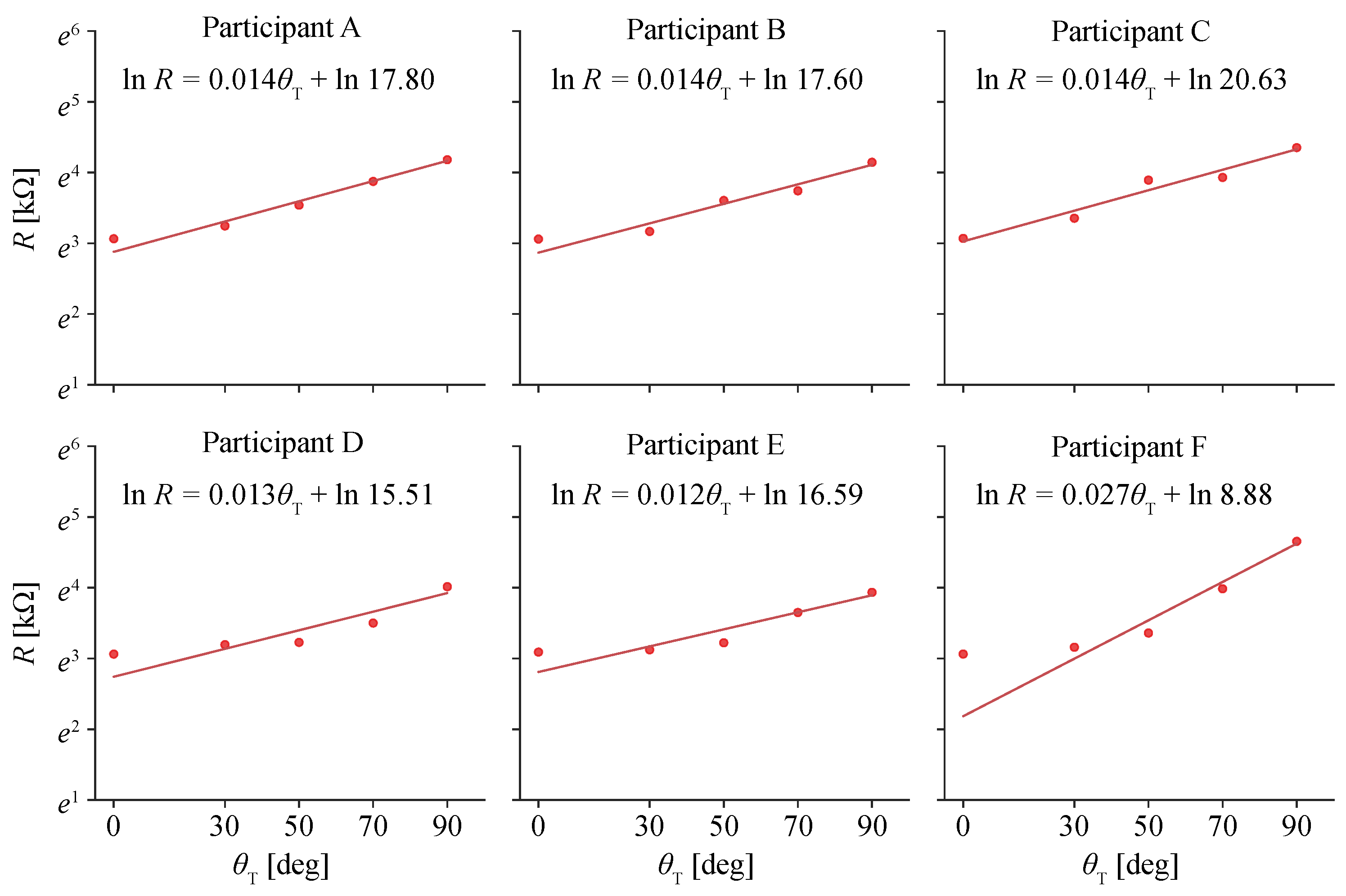
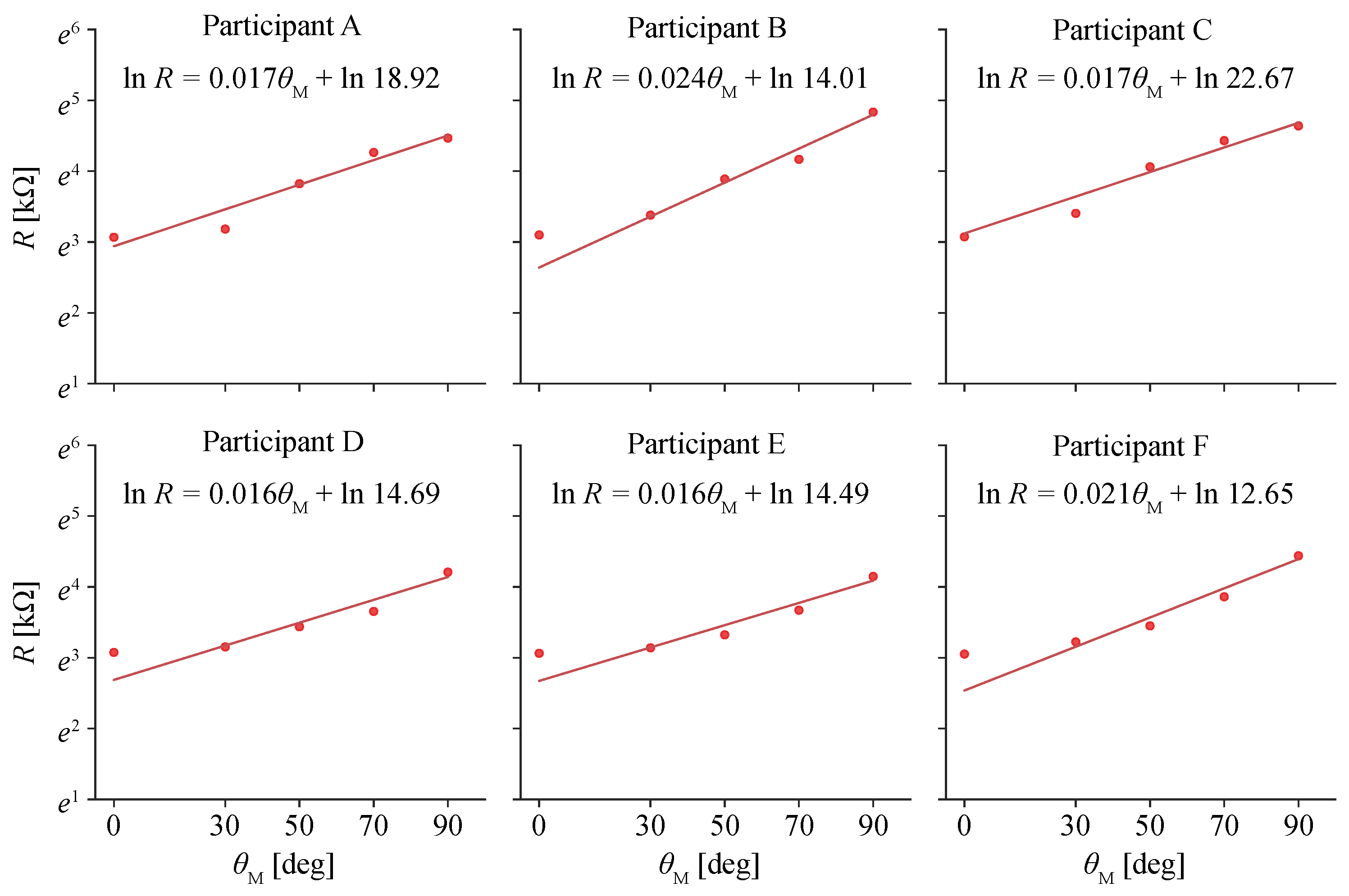
The calibration results for the thumb and middle finger joints are shown in Figure 6 and Figure 7, respectively, with flex sensor resistance R and joint angles θ for each participant. The values represent the average of two trials per participant. The results reveal variations in flex sensor readings between participants, even at the same joint angles. Although there are few variations of the sensor itself, the variation in measurement is not small because it is attached to a glove and worn by a participant, including individual differences and differences due to misalignment when the glove is worn.
To address these discrepancies, a calibration model was developed to describe the relationship between sensor resistance R and joint angle θ , as shown in Equation (5). The model is based on a logarithmic function, which accounts for the characteristics of the flex sensor’s resistance change. Model parameters α sense and β sense were determined using the least squares method, with the results summarized in Table 1. Based on this model, calibration should be performed for each user using representative flexion angles before device usage.
ln   R = α sense θ + ln   β sense .

2.4. Distributed Haptic Stimulus Presentation Device

For haptic feedback, two types of devices are used: one for fingers and one for the palm, as shown in Figure 8. These devices use silicone rubber bands that are wound by a motor to apply pressure with skin deformation to the fingers and palm. The devices allow for distributed feedback by independently controlling the stimulus intensity for each location. A relatively small servo motor (Dynamixel XC-330-T288-T, ROBOTIS Co., Ltd., Seoul, Republic of Korea) was used due to its light weight and ease of control for the prototype system. In the future, even smaller servo motors could be developed to further improve ease of mounting. The device weights are 30 g for the finger unit and 62 g for the palm unit, with a total weight of 212 g.
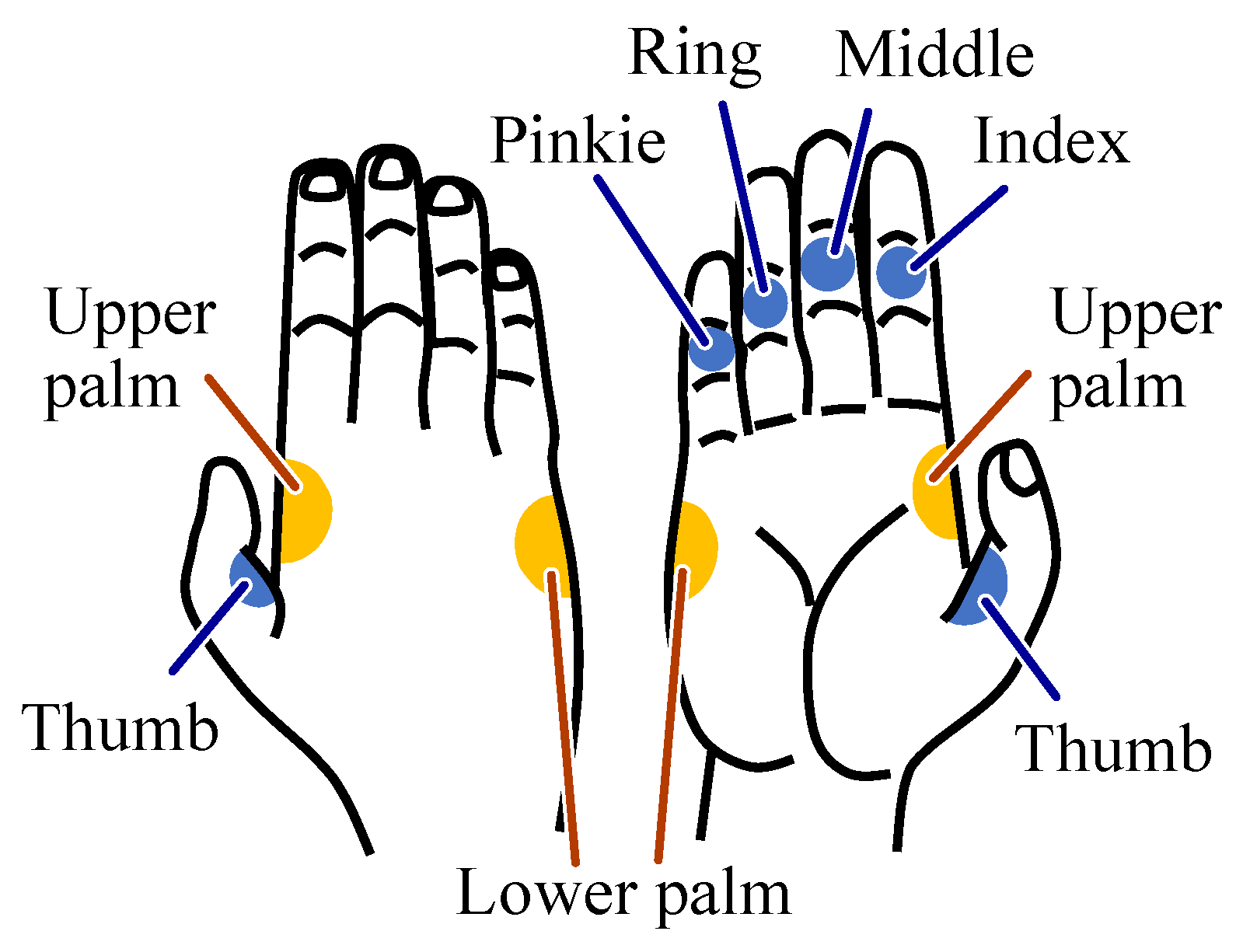
The presentation points for the device are based on the contact areas during face-to-face handshakes [28], as shown in Figure 9. These include seven specific areas:
  • Middle phalanx of the index, middle, ring, and little fingers.
  • Proximal phalanx of the thumb.
  • Upper and lower regions of the palm.
Figure 9. Pressure stimulus presentation points.
Electronics 14 00537 g009
Six devices were attached to a glove, as shown in Figure 8, to allow pressure feedback at these locations. The devices do not significantly restrict finger movement, permitting free flexion and extension.

2.5. Relationship Between Presentation Pressure and Motor Angle

In this section, the relationship between the target presentation pressure P cmd and the motor rotation angle ϕ , which is simply expressed by Equation (3), is investigated. The distributed haptic stimulus presentation device is controlled by adjusting the motor’s rotation angle. However, the relationship between motor rotation angles and the stimulus intensity at different locations is not well understood. To address this, experiments were conducted to model the relationship between motor rotation angles and pressure intensities for each location. Three male participants in their 20s participated in this experiment.

2.5.1. Experimental Apparatus

The experimental setup included the distributed haptic stimulus presentation device and pressure sensors. The pressure sensors were placed between the device’s band and the hand to measure contact pressure. For the palm, medium-sized pressure sensors (FSR402, Interlink Electronics, Inc., Fremont, CA, USA) were used, while small pressure sensors (FSR400, Interlink Electronics, Inc.) were used for the fingers.

2.5.2. Experimental Procedure

The procedure was as follows:
  • The motor was operated in current-control mode to lightly touch the band to the pressure sensor, and this position was set as the initial angle.
  • The motor was rotated in position-control mode in increments of 10° from the initial angle, and the pressure sensor readings were recorded at each step.
  • The motor was rotated to its maximum angle, set at 190° for the fingers and 310° for the palm.
  • The procedure was repeated twice for each of the six presentation devices (four fingers and two palm areas).

2.5.3. Experimental Results

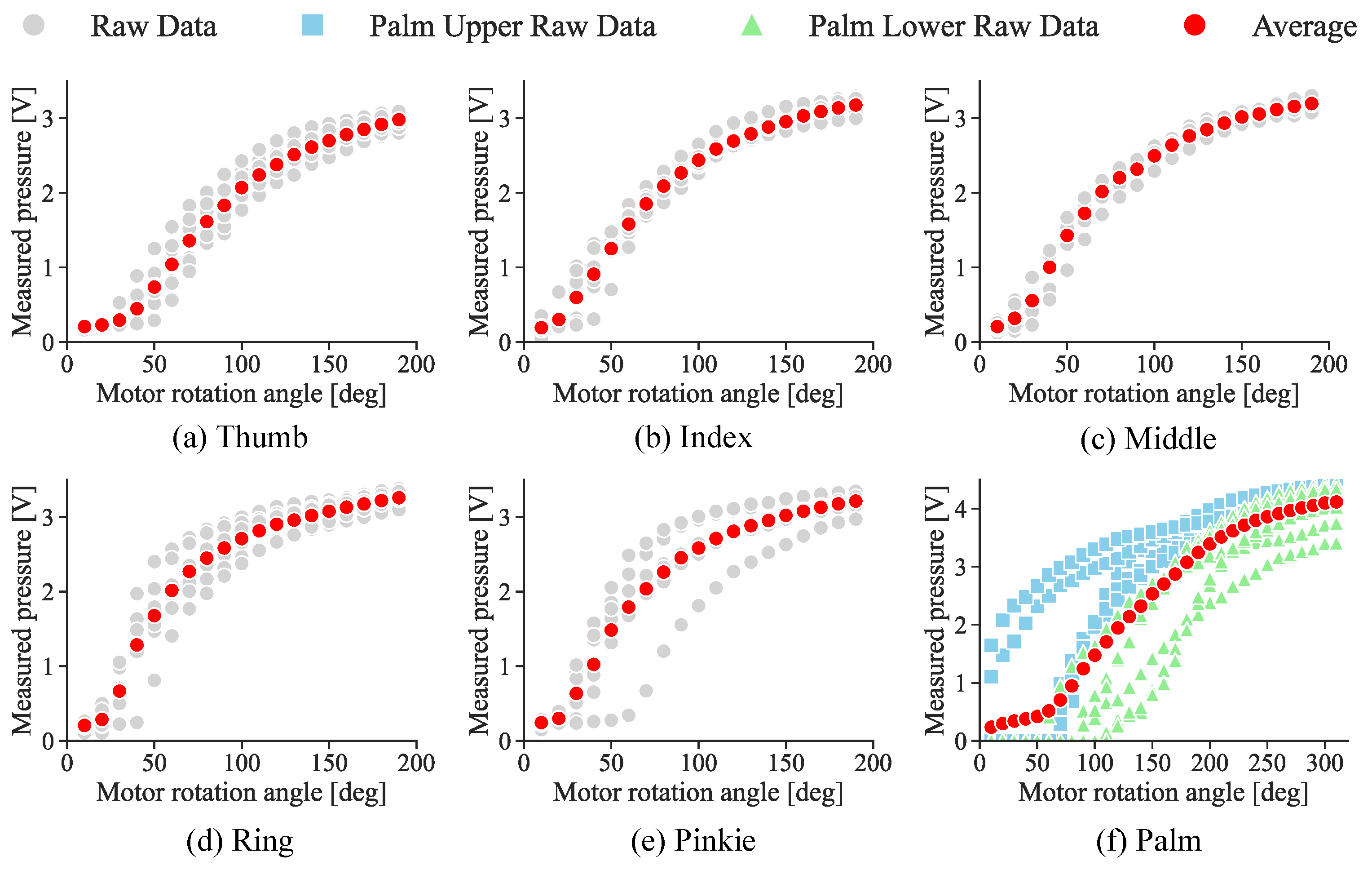
To construct a model describing the relationship between target pressure P cmd and motor rotation angle ϕ , a data table was first created based on the experimental results. The results are shown in Figure 10. For the fingers, the results showed low variance between participants and trials. Therefore, the average values for each finger were used to create the data table.
For the palm, a single motor controls the pressure for two regions (upper and lower), and the data table was constructed based on the averaged results for these two regions. Although differences between the two regions were observed, both showed a tendency for pressure to increase with motor angle. Linear interpolation is used to provide continuous stimulus intensity control between the discrete values in the data table. It is assumed to be an individual difference due to the hardness of the skin and the size and shape of the hand. Future research could improve the stability of the system by personally optimizing the system for these human characteristics.

3. Development of Mutual Interaction Pressure Distribution Model

In this section, we experimentally investigate the mutual interactive effects of pressure on each hand site in a handshake in a face-to-face environment using the developed measurement system. We also propose a model to represent the mutual interaction, and obtain from the measurement experimental results parameters representing the weights of the interactions that the model has.

3.1. Interaction Pressure Distribution Model

The interaction pressure distribution model, represented by Equation (6), is a foundational model designed to capture mutual handshaking behavior in a simplified manner. This initial model does not incorporate nonlinear elements, focusing instead on providing a straightforward representation of the interaction dynamics. Future studies will aim to refine and validate the model, incorporating more detailed elements to enhance its accuracy and applicability. In the current model, each stimulus is determined based on the mutual finger joint angles of both participants. In this model, θ ST , θ SM , θ OT , and θ OM represent the finger joint angles of the self and partner for the thumb and middle finger, respectively. P cmd denotes the target pressure intensity, P min and P max represent the minimum and maximum pressures, and α and β are the weights that adjust the intensity for each region. θ M 0 and θ T 0 are the handshake initiation angles, while θ Mmax and θ Tmax represent the maximum flexion angles. θ Mmax and θ Tmax are set to 105° and 100°, respectively. By this model, the target pressure P cmd varies between a minimum value P max and a maximum value P min . The model enables the distributed haptic stimulus to be controlled dynamically during remote handshakes based on measured joint angles. The parameters of the model are obtained by experimentation.
P cmd = α 2 θ ST θ T 0 θ Tmax θ T 0 + α 2 θ SM θ M 0 θ Mmax θ M 0 + β 2 θ OT θ T 0 θ Tmax θ T 0 + β 2 θ OM θ M 0 θ Mmax θ M 0 × ( P max P min ) + P min .

3.2. Experimental Objectives

The objectives of this experiment are as follows:
  • Investigate whether the pressure distribution is mutual interactive.
  • Determine α and β , which represent the relative weights of each part of the hand.
  • Determine P min and P max , which represent the minimum and maximum intensities at each part of the hand.
  • Determine θ T 0 and θ M 0 for joint angle thresholds.
By analyzing the pressure applied to different regions of the hand during a handshake in a face-to-face environment, region-specific weights are calculated. These weights are applied to remote handshakes to provide haptic feedback that replicates the mutual interaction observed in face-to-face handshakes.
Handshakes allow for diverse expressions, such as conveying emotions or intentions, through varying grip intensities [8,25,29]. To replicate these expressions in remote environments, the minimum and maximum grip pressures during a handshake are measured and applied to the remote handshake system.
In face-to-face handshakes, physical contact with the partner restricts finger flexion. The finger joint angles during this interaction are referred to as handshake angles. In contrast, remote handshakes lack physical contact, allowing unrestricted finger movement. Therefore, the handshake initiation angle is predefined, and haptic feedback begins when this angle is exceeded. This experiment records the handshake angles in face-to-face environments, which are used as the handshake initiation angles in remote handshakes.

3.3. Experimental Apparatus

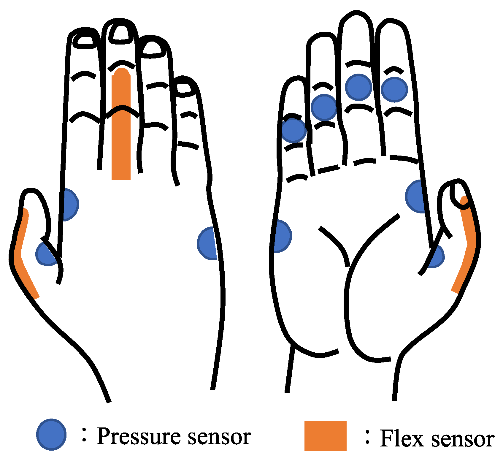
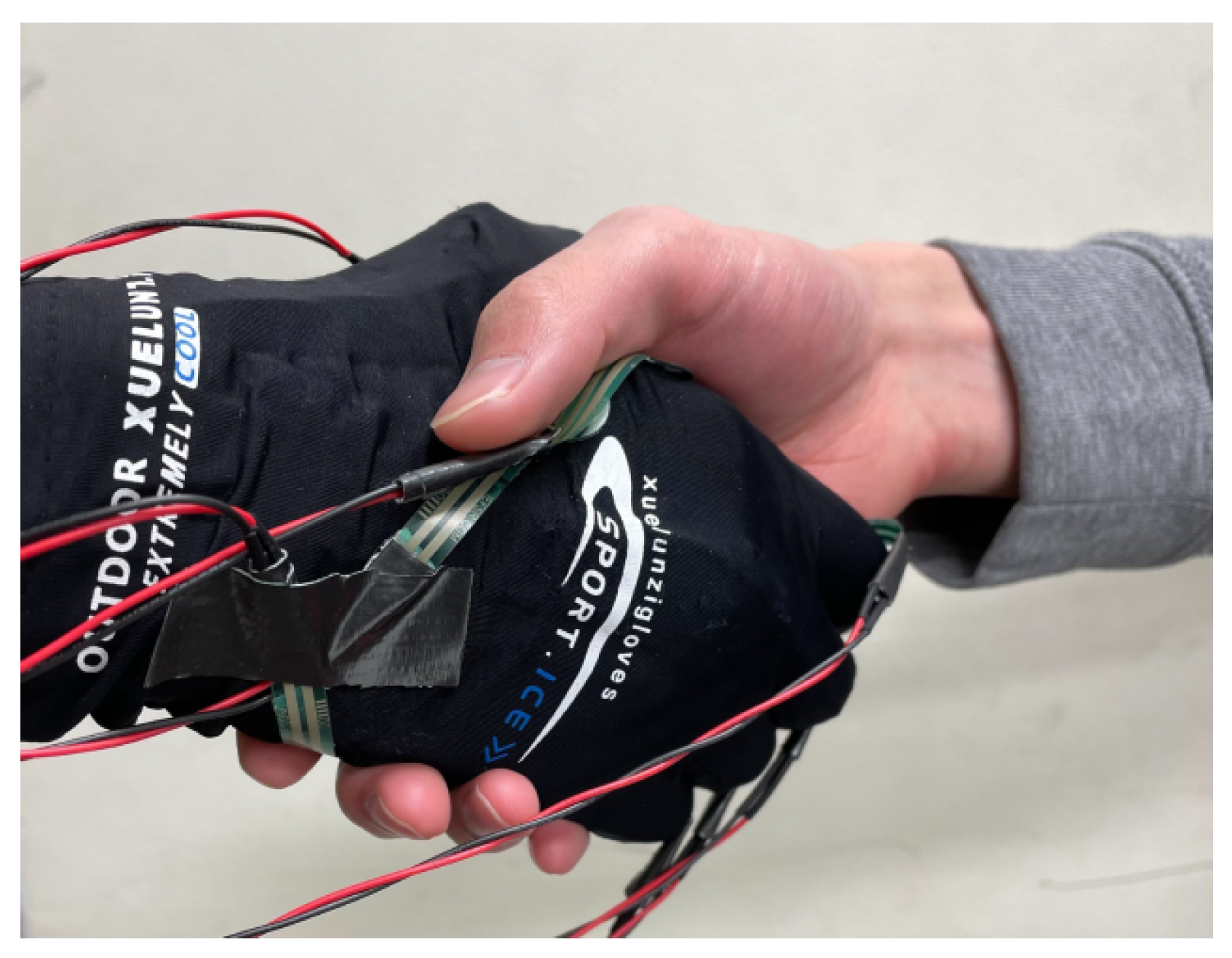
The experimental setup includes a finger joint angle measurement device and pressure sensors. The FSR sensors are mounted on the glove of the joint angle measurement device, as shown in Figure 11, with positions corresponding to the stimulus presentation points: five on the fingers and two on the palm. Medium-sized pressure sensors (FSR402, Interlink Electronics, Inc.) are used for the palm, while small pressure sensors (FSR400, Interlink Electronics, Inc.) are used for the fingers. As shown in Figure 12, one participant wears the device and performs a handshake with another participant to measure the pressure applied to each region of the hand.

3.4. Experimental Procedure

The experiment was conducted as follows:
  • Participants were divided into two roles: Lead participant and following participant. Only the following participant wore the measurement device.
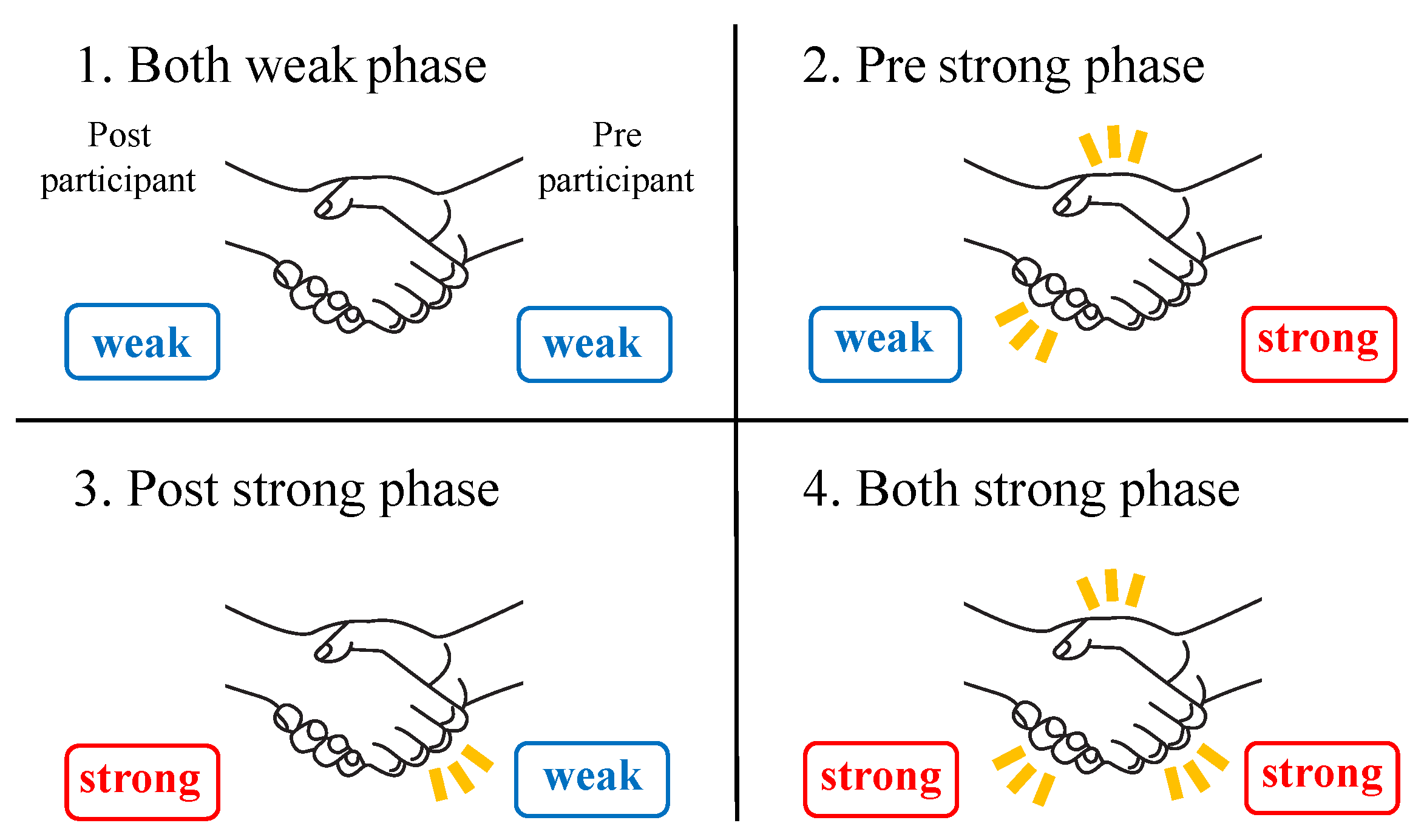
  • Both Weak Phase: Both participants performed a handshake with a weak grip.
  • Pre-Strong Phase: Only the lead participant gripped strongly, while the following participant maintained a weak grip.
  • Post-Strong Phase: Only the following participant gripped strongly, while the lead participant maintained a weak grip.
  • Both Strong Phase: Both participants gripped strongly during the handshake.
The phase transitions are illustrated in Figure 13. Each phase lasted 5 s, except for the Both Weak Phase, which lasted 10 s to account for handshake initiation. A metronome was used to ensure consistent timing, and a 5-s interval was provided between phases for adjustments. These interval values were determined empirically by the authors. Reasonable values were assumed for the duration of stimulus application in a real handshake. Participants were instructed to perform handshakes within the range of the weakest and strongest grips, avoiding excessively weak or painful grips. Nine male participants in their 20s participated in the experiment, with six assigned as lead participants and three as following participants. Each pair performed the handshake sequence, resulting in a total of 18 trials.

3.5. Experimental Results

3.5.1. Fingers

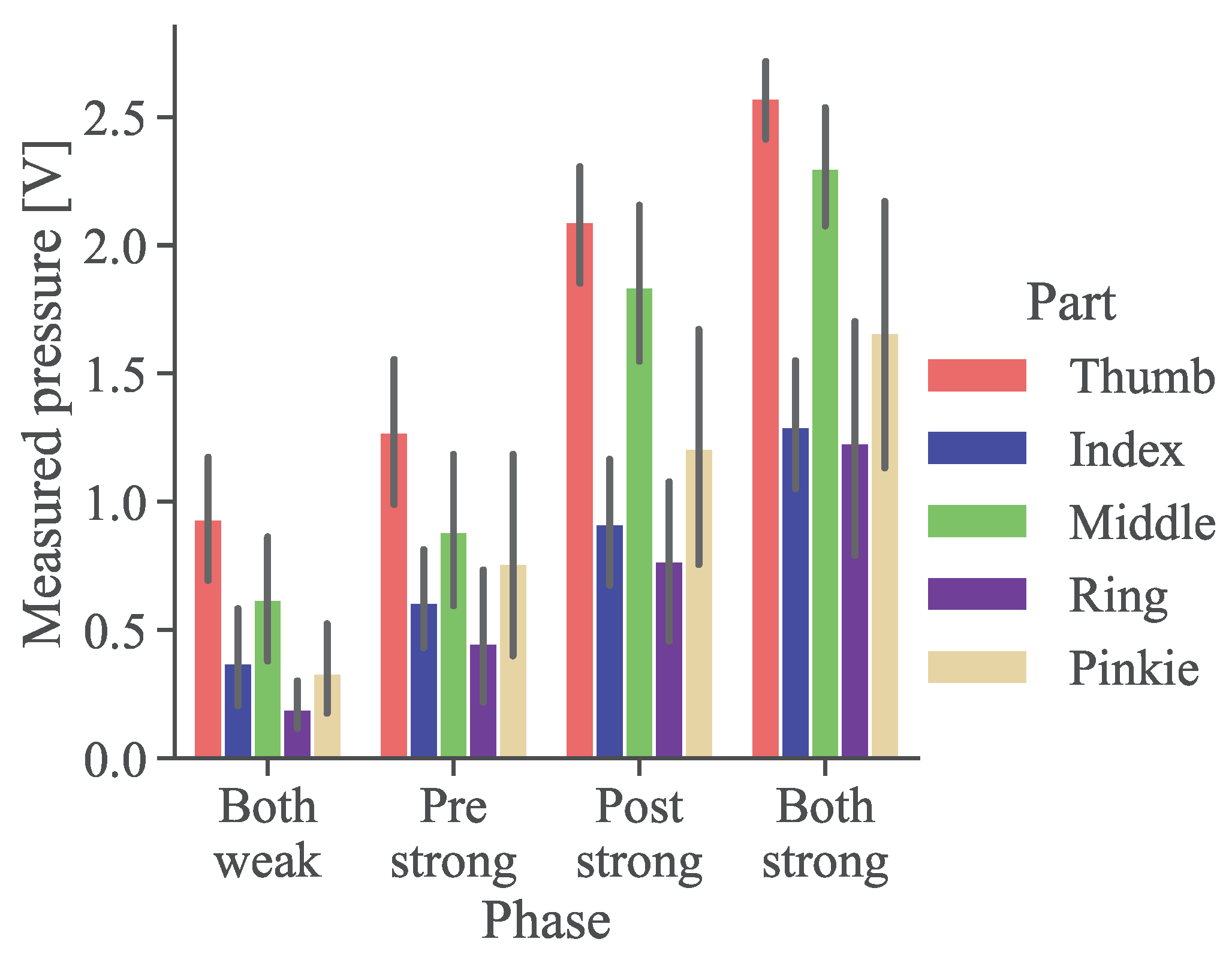
The average pressure results for the five fingers during each phase are shown in Figure 14. The pressure values are expressed as voltages, with higher values indicating stronger pressures. From the Both Weak and Both Strong Phases, the minimum ( P min ) and maximum ( P max ) pressures for each finger are derived, as shown in Table 2. Additionally, the weights α (self) and β (partner) are calculated from the differences in pressure measurements across phases, as summarized in Table 3.

3.5.2. Palm

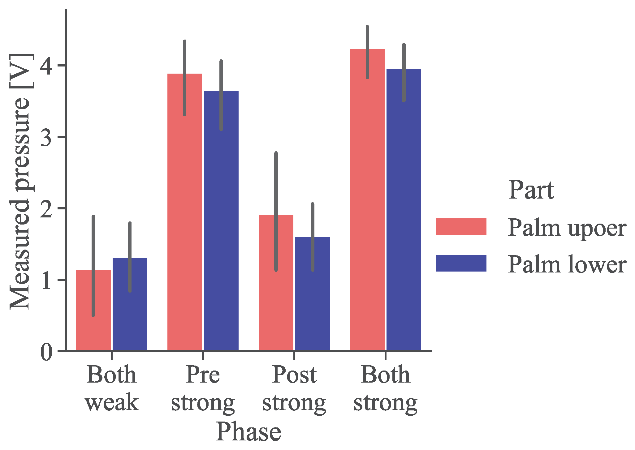
The average pressure results for the two regions of the palm during each phase are shown in Figure 15. Since the palm is controlled by a single motor in the haptic device, the model was constructed based on the average results from the two regions. The measurements indicate minimal differences between the upper and lower palm regions across all phases, suggesting that similar pressures act on both areas during a handshake. Thus, the haptic device’s single-motor control can replicate the pressures observed in face-to-face handshakes. The minimum ( P min ) and maximum ( P max ) pressures for the palm are determined from the Both Weak and Both Strong Phases, as shown in Table 4. Additionally, the weights α (self) and β (partner) for the palm are calculated and summarized in Table 5.

3.5.3. Finger Joint Angles

The results of the finger joint angles θ measured during the Both Weak Phase are shown in Table 6 for each following participant.
First, for the thumb, small angles ranging from 9.57° to 28.6° were recorded. Even in a relaxed state, fingers naturally exhibit some degree of flexion. Therefore, the participant with a measured value of 9.57° likely did not consciously flex their thumb interphalangeal joint during the handshake. This variation highlights not only differences in flexion angles but also whether the thumb is consciously flexed or not. Consequently, if a handshake initiation angle is set for the thumb, participants who do not flex their thumb during the handshake may fail to trigger the handshake detection, making it impossible to perform the handshake. To address this issue, no handshake initiation angle is set for the thumb.
Next, for the middle finger, joint angles ranging from 30.9° to 55.1° were recorded, with a difference of approximately 20° among participants. Based on these results, the minimum angle of 30.9° is chosen as the handshake initiation angle.
Using the minimum value instead of the average is crucial for remote handshakes, where it is essential to ensure that pressure presentation begins when the participant’s finger flexion reaches an angle comparable to that of a face-to-face handshake. In remote handshakes, participants wearing the device are expected to flex their fingers to a degree similar to a face-to-face handshake. If the average value were used, some participants might not flex their fingers sufficiently to reach the required angle, leading to issues where the handshake cannot be initiated. By using the minimum value, the handshake can be initiated earlier than during a typical face-to-face handshake, but this approach ensures that the handshake is reliably detected for all participants.
Based on these considerations, this study uses the middle finger joint angle of 30.9° as the handshake initiation angle θ T 0 , as shown in Table 7. Pressure presentation is triggered when the measured angle exceeds this value.

4. Discussion

4.1. Grip Strength Measurement

In this study, finger joint angles were used as a substitute for grip strength during handshakes, and feedback for stimulus intensity was provided based on measurements obtained from flex sensors. Flex sensors are compact and lightweight, and they do not require special environments such as base stations often used in virtual reality (VR) systems, making them adaptable to a variety of remote communication environments. However, flex sensors are also highly susceptible to factors such as hand size and attachment conditions. When the sensor and the stimulus presentation area overlap, as in this study, these factors may further increase variability. Consequently, the measurement accuracy of this method is considered inferior to that of other approaches.
If the system were designed solely for use in VR environments, optical motion capture with trackers would likely provide higher measurement accuracy. Alternatively, if the system were intended only for environments such as video chat, feedback using grip force measurements, as demonstrated by Dragusanu et al. [30], could also be considered. While flex sensors were employed in this study to support various environments, it should be noted that other measurement methods might be more appropriate depending on the specific application environment.

4.2. Haptic Stimulus Presentation Method

This study utilized pressure presentation by winding a band to replicate the tactile sensations of a handshake. This method induces skin deformation along with pressure, enabling realistic reproduction of the contact surface condition during a handshake. Furthermore, the ability to individually adjust stimulus intensity and its high responsiveness make this method effective for replicating handshakes where stimuli are distributed across multiple regions and vary in intensity.
However, because the band is wound around the finger, the stimulus not only acts on the palmar side of the finger, where the stimulus is intended, but also on the dorsal (nail) side. For devices presenting vibrational stimuli, a method has been proposed to stimulate the nail side as a substitute for the palmar side to simulate object contact [31], suggesting that these two areas are closely related in terms of stimulus perception. However, for pressure stimuli like those used in this study, the effects on perception are not yet clear. It should be noted that the additional stimulus on the nail side may alter the perception of a handshake compared to real-world conditions.

4.3. Individual Differences in Handshake

This study developed an interaction force model based on handshake measurements in real-world conditions. This model is expected to enable a variety of expressive handshakes in remote environments, depending on the situation. However, handshake expressions are influenced not only by situational factors but also by individual characteristics.
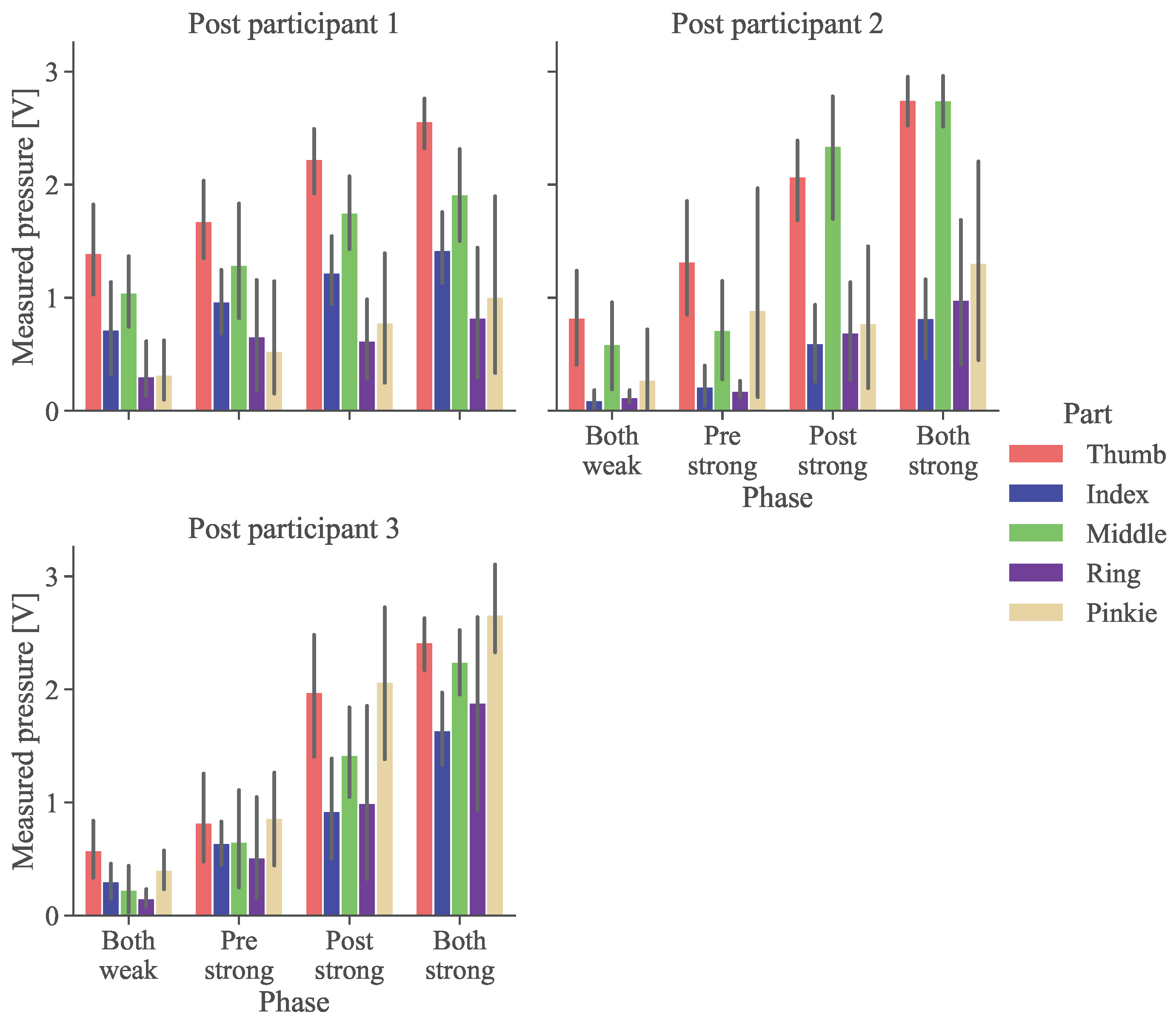
The pressure measurement results for the fingers are shown in Figure 16 for each following participant. Differences in grip styles were observed among participants, such as using all fingers or primarily the thumb and middle finger for gripping. These variations are likely related to individual characteristics, such as personality, gender, or hand size.
The model developed in this study uses average values, which do not account for such individual differences. However, if stimulus intensity ranges or handshake initiation angles can be adjusted to match individual characteristics, it would be possible to represent these differences. Therefore, further improvements to the model will be considered in future work.
In addition, this study is a pilot study proposing a relatively simple model. Detailed model comparisons using results from a large number of participants will be needed in the future. It is an important question as to how much the model detail is related to the reality of the sensation of the handshake being reproduced.

5. Conclusions

The primary objectives of this study were to experimentally investigate the mutual interaction of self- and partner-induced actions in determining pressure distribution during a handshake and to develop a remote handshake system based on these findings. Through experiments conducted in face-to-face environments, it was demonstrated that the pressure distribution during a handshake is region-dependent and influenced by the actions of both participants. Specifically, the palm was shown to be more affected by the partner’s actions, whereas the fingers were more influenced by the self’s movements.
Based on these findings, an interaction force model was developed to calculate stimulus intensities, incorporating region-specific weights for different hand regions. This model serves as the basis for the proposed remote handshake system, which integrates flex sensors to measure finger joint angles and a distributed haptic stimulus presentation device. The system aims to replicate the tactile dynamics of a handshake by presenting distributed pressure stimuli that reflect mutual interaction.
While the study successfully established the interaction model and constructed the remote handshake system, the system’s effectiveness in replicating real-world handshake experiences has not yet been validated. Future work will focus on evaluating the system’s performance and exploring its application in diverse remote communication scenarios. In our previous study [26], the proposed system was used in conjunction with visual information to reproduce effective handshake sensations. Further research is needed, including investigation of conditions suitable for communication. Additionally, improvements to the interaction force model, such as accommodating individual differences in grip styles and preferences, will be considered to enhance the realism and adaptability of the system.

Author Contributions

Conceptualization, S.W. and H.N.; methodology, S.W. and H.N.; software, S.W.; validation, S.W. and H.N.; formal analysis, S.W. and H.N.; investigation, S.W. and H.N.; resources, H.N., Y.T. and Y.Y.; data curation, S.W. and H.N.; writing—original draft preparation, S.W.; writing—review and editing, H.N., Y.T. and Y.Y.; visualization, S.W. and H.N.; supervision, H.N. and Y.Y.; project administration, H.N.; funding acquisition, H.N. All authors have read and agreed to the published version of the manuscript.

Funding

This work was supported by JSPS KAKENHI under Grant Numbers JP21KK0182, JP24K21323, and JP24K07405.

Institutional Review Board Statement

All subjects gave their informed consent for inclusion before they participated in the study. The study was conducted according to the guidelines of the Declaration of Helsinki, and approved by the ethical review board of the faculty of engineering of Kobe University (protocol code 04-52 and 13 January 2023).

Informed Consent Statement

Informed consent was obtained from all participants involved in the study.

Data Availability Statement

The original contributions presented in this study are included in the article. Further inquiries can be directed to the corresponding author.

Acknowledgments

This article is a revised and expanded version of a conference paper entitled “Emotional VR handshake by controlling skin deformation distribution”, which was presented at the AsiaHaptics 2024, Kuala Lumpur, Malaysia, 28–30 October 2024 [26].

Conflicts of Interest

The authors declare no conflicts of interest.

References

  1. Hans, A.; Hans, E. Kinesics, haptics and proxemics: Aspects of non-verbal communication. IOSR J. Humanit. Soc. Sci. (IOSR-JHSS) 2015, 20, 47–52. [Google Scholar]
  2. Sundaram, D.S.; Webster, C. The role of nonverbal communication in service encounters. J. Serv. Mark. 2000, 14, 378–391. [Google Scholar] [CrossRef]
  3. Van Erp, J.B.; Toet, A. Social touch in human–computer interaction. Front. Digit. Humanit. 2015, 2, 2. [Google Scholar] [CrossRef]
  4. Tsetserukou, D. Haptihug: A novel haptic display for communication of hug over a distance. In Haptics: Generating and Perceiving Tangible Sensations. Proceedings of the 7th International Conference EuroHaptics 2010, Amsterdam, The Netherlands, 8–10 July 2010; Springer: Berlin/Heidelberg, Germany, 2010; pp. 340–347. [Google Scholar]
  5. Teyssier, M.; Bailly, G.; Pelachaud, C.; Lecolinet, E. Conveying emotions through device-initiated touch. IEEE Trans. Affect. Comput. 2020, 13, 1477–1488. [Google Scholar] [CrossRef]
  6. Haritaipan, L.; Hayashi, M.; Mougenot, C. Design of a massage-inspired haptic device for interpersonal connection in long-distance communication. Adv. Hum.-Comput. Interact. 2018, 2018, 5853474. [Google Scholar] [CrossRef]
  7. Katsumi, Y.; Kim, S.; Sung, K.; Dolcos, F.; Dolcos, S. When nonverbal greetings “make it or break it”: The role of ethnicity and gender in the effect of handshake on social appraisals. J. Nonverbal Behav. 2017, 41, 345–365. [Google Scholar] [CrossRef]
  8. Vigni, F.; Knoop, E.; Prattichizzo, D.; Malvezzi, M. The role of closed-loop hand control in handshaking interactions. IEEE Robot. Autom. Lett. 2019, 4, 878–885. [Google Scholar] [CrossRef]
  9. Nakanishi, H.; Tanaka, K.; Wada, Y. Remote handshaking: Touch enhances video-mediated social telepresence. In Proceedings of the 2014 SIGCHI Conference on Human Factors in Computing Systems, Toronto, ON, Canada, 26 April–1 May 2014; pp. 2143–2152. [Google Scholar]
  10. Ammi, M.; Demulier, V.; Caillou, S.; Gaffary, Y.; Tsalamlal, Y.; Martin, J.C.; Tapus, A. Haptic human-robot affective interaction in a handshaking social protocol. In Proceedings of the Tenth Annual ACM/IEEE International Conference on Human-Robot Interaction, Portland, OR, USA, 2–5 March 2015; pp. 263–270. [Google Scholar]
  11. Faisal, M.; Laamarti, F.; El Saddik, A. Digital Twin Haptic Robotic Arms: Towards Handshakes in the Metaverse. Electronics 2023, 12, 2603. [Google Scholar] [CrossRef]
  12. Baik, S.; Park, S.; Park, J. Haptic glove using tendon-driven soft robotic mechanism. Front. Bioeng. Biotechnol. 2020, 8, 541105. [Google Scholar]
  13. Iqbal, J.; Tsagarakis, N.; Caldwell, D. Four-fingered lightweight exoskeleton robotic device accommodating different hand sizes. Electron. Lett. 2015, 51, 888–890. [Google Scholar] [CrossRef]
  14. Khurshid, R.P.; Fitter, N.T.; Fedalei, E.A.; Kuchenbecker, K.J. Effects of grip-force, contact, and acceleration feedback on a teleoperated pick-and-place task. IEEE Trans. Haptics 2016, 10, 40–53. [Google Scholar] [CrossRef]
  15. Maereg, A.T.; Nagar, A.; Reid, D.; Secco, E.L. Wearable vibrotactile haptic device for stiffness discrimination during virtual interactions. Front. Robot. AI 2017, 4, 42. [Google Scholar] [CrossRef]
  16. Nagano, H.; Takenouchi, H.; Cao, N.; Konyo, M.; Tadokoro, S. Tactile feedback system of high-frequency vibration signals for supporting delicate teleoperation of construction robots. Adv. Robot. 2020, 34, 730–743. [Google Scholar] [CrossRef]
  17. Tawa, S.; Nagano, H.; Tazaki, Y.; Yokokohji, Y. Extended phantom sensation: Vibrotactile-based movement sensation in the area outside the inter-stimulus. Adv. Robot. 2021, 35, 268–280. [Google Scholar] [CrossRef]
  18. Tawa, S.; Nagano, H.; Tazaki, Y.; Yokokohji, Y. Three-Dimensional Position Presentation Via Head and Waist Vibrotactile Arrays. IEEE Trans. Haptics 2023, 17, 319–333. [Google Scholar] [CrossRef] [PubMed]
  19. Nagano, H.; Sase, K.; Konyo, M.; Tadokoro, S. Wearable suction haptic display with spatiotemporal stimulus distribution on a finger pad. In Proceedings of the 2019 IEEE World Haptics Conference (WHC), Tokyo, Japan, 9–12 July 2019; pp. 389–394. [Google Scholar]
  20. Abad, A.C.; Reid, D.; Ranasinghe, A. A Novel Untethered Hand Wearable with Fine-Grained Cutaneous Haptic Feedback. Sensors 2022, 22, 1924. [Google Scholar] [CrossRef]
  21. Yem, V.; Kajimoto, H. Wearable tactile device using mechanical and electrical stimulation for fingertip interaction with virtual world. In Proceedings of the 2017 IEEE Virtual Reality (VR), Los Angeles, CA, USA, 18–22 March 2017; pp. 99–104. [Google Scholar]
  22. Yamaguchi, S.; Hiraki, T.; Ishizuka, H.; Miki, N. Handshake Feedback in a Haptic Glove Using Pouch Actuators. Actuators 2023, 12, 51. [Google Scholar] [CrossRef]
  23. Yarosh, S.; Mejia, K.; Unver, B.; Wang, X.; Yao, Y.; Campbell, A.; Holschuh, B. SqueezeBands: Mediated social touch using shape memory alloy actuation. Proc. ACM Hum.-Comput. Interact. 2017, 1, 1–18. [Google Scholar] [CrossRef]
  24. Chaplin, W.F.; Phillips, J.B.; Brown, J.D.; Clanton, N.R.; Stein, J.L. Handshaking, gender, personality, and first impressions. J. Personal. Soc. Psychol. 2000, 79, 110. [Google Scholar] [CrossRef]
  25. Bailenson, J.N.; Yee, N.; Brave, S.; Merget, D.; Koslow, D. Virtual interpersonal touch: Expressing and recognizing emotions through haptic devices. Hum.-Comput. Interact. 2007, 22, 325–353. [Google Scholar]
  26. Watatani, S.; Nagano, H.; Tazaki, Y.; Yokokohji, Y. Emotional VR handshake by controlling skin deformation distribution. In Proceedings of the 6th International Conference AsiaHaptics 2024, Kuala Lumpur, Malaysia, 28–30 October 2024. B04. [Google Scholar]
  27. Rijpkema, H.; Girard, M. Computer animation of knowledge-based human grasping. ACM Siggraph Comput. Graph. 1991, 25, 339–348. [Google Scholar] [CrossRef]
  28. Knoop, E.; Bächer, M.; Wall, V.; Deimel, R.; Brock, O.; Beardsley, P. Handshakiness: Benchmarking for human-robot hand interactions. In Proceedings of the 2017 IEEE/RSJ International Conference on Intelligent Robots and Systems (IROS), Vancouver, BC, Canada, 24–28 September 2017; pp. 4982–4989. [Google Scholar]
  29. Tong, Q.; Wei, W.; Guo, Y.; Jin, T.; Wang, Z.; Zhang, H.; Zhang, Y.; Wang, D. Distant handshakes: Conveying social intentions through multi-modal soft haptic gloves. IEEE Trans. Affect. Comput. 2024; early access. [Google Scholar] [CrossRef]
  30. Dragusanu, M.; Iqbal, Z.; Villani, A.; D’Aurizio, N.; Prattichizzo, D.; Malvezzi, M. Hans: A haptic system for human-to-human remote handshake. In Proceedings of the 2022 9th IEEE RAS/EMBS International Conference for Biomedical Robotics and Biomechatronics (BioRob), Seoul, Republic of Korea, 21–24 August 2022; pp. 1–8. [Google Scholar]
  31. Preechayasomboon, P.; Rombokas, E. Haplets: Finger-worn wireless and low-encumbrance vibrotactile haptic feedback for virtual and augmented reality. Front. Virtual Real. 2021, 2, 738613. [Google Scholar] [CrossRef]
Figure 1. Concept of tele handshake system based on virtual reproduction of pressure distribution.
Electronics 14 00537 g001
Figure 2. Finger joint measurement points.
Electronics 14 00537 g002
Figure 3. Flex sensor installation.
Electronics 14 00537 g003
Figure 4. Circuit for reading flex sensor values.
Electronics 14 00537 g004
Figure 5. Measurement of finger joint angles using a goniometer.
Electronics 14 00537 g005
Figure 6. Relationship between flex sensor resistance and thumb joint angle.
Electronics 14 00537 g006
Figure 7. Relationship between flex sensor resistance and middle finger joint angle.
Electronics 14 00537 g007
Figure 8. Distributed haptic stimulus presentation device. (b,c) are revised from the previous study [26].
Electronics 14 00537 g008
Figure 10. Site-specific results of pressure measurements and their averages according to motor rotation angle. (a) Thumb. (b) Index. (c) Middle. (d) Ring. (e) Pinkie. (f) Palm.
Electronics 14 00537 g010
Figure 11. Sensor arrangement of measurement device.
Electronics 14 00537 g011
Figure 12. Handshake measurement experiment in a face-to-face environment.
Electronics 14 00537 g012
Figure 13. Handshake strength phases.
Electronics 14 00537 g013
Figure 14. Pressure sensor values measured at the fingers for each phase. The figure shows the average values and standard deviations for the pressure across all participants.
Electronics 14 00537 g014
Figure 15. Pressure sensor values measured at the palm for each phase. The figure shows the average values and standard deviations for the pressure across all participants.
Electronics 14 00537 g015
Figure 16. Comparison of pressure results measured at the fingers among post participants.
Electronics 14 00537 g016
Table 1. Exponential model parameters for each participant.
ParameterParticipantMeanS.D.
ABCDEF
Thumb α sense 0.014 0.014 0.014 0.013 0.012 0.027 0.016 0.005
β sense 17.80 17.60 20.63 15.51 16.59 8.88 16.17 3.61
Middle α sense 0.017 0.024 0.017 0.016 0.016 0.021 0.019 0.003
β sense 18.92 14.01 22.67 14.69 14.49 12.65 16.24 3.46
Table 2. Minimum and maximum values for finger pressure in the interaction pressure model.
Part P min [ V ] P max [ V ]
Thumb0.932.57
Index0.371.29
Middle0.622.30
Ring0.191.23
Pinkie0.331.66
Table 3. Gain parameters ( α and β ) for the fingers in the interaction pressure model.
Part α (Self Weight) β (Partner Weight)
Thumb0.770.23
Index0.700.30
Middle0.820.18
Ring0.690.31
Pinkie0.670.33
Table 4. Minimum and maximum values for palm pressure in the interaction pressure model.
Part P min [ V ] P max [ V ]
Palm1.234.10
Table 5. Gain parameters ( α and β ) for the palm in the interaction pressure model.
Part α (Self Weight) β (Partner Weight)
Palm0.170.83
Table 6. Finger joint angles during handshake.
PartFollowing ParticipantMeanS.D.
123
Thumb28.6°9.57°22.4°20.2°7.9
Middle55.1°43.2°30.9°43.1°9.9
Table 7. Finger joint angle for starting handshake in remote handshake.
θ T 0 θ M 0
30.9°
Disclaimer/Publisher’s Note: The statements, opinions and data contained in all publications are solely those of the individual author(s) and contributor(s) and not of MDPI and/or the editor(s). MDPI and/or the editor(s) disclaim responsibility for any injury to people or property resulting from any ideas, methods, instructions or products referred to in the content.