1. Introduction
Globally, interest in eco-friendly mobility is rising as a solution to carbon dioxide emissions and the challenges posed by internal combustion engine vehicles. Consequently, there is a demand for high efficiency, high output, miniaturization, and reliability in traction motors, which are key components of eco-friendly mobility. Within the eco-friendly mobility sector, electric mobility commonly employs Interior Permanent Magnet Synchronous Motors (IPMSMs), which offer advantages in high efficiency, high power, and motor miniaturization [
1,
2]. However, reliability and safety are essential for the driver due to the nature of the mobility.
As the mechanical load increases, IPMSMs can be exposed to high mechanical impacts, increasing the possibility of unexpected faults [
3,
4,
5]. Among these, eccentricity faults, which are addressed in this paper, lead to increased vibration and noise due to the imbalance of the magnetic field. The early diagnosis of eccentricity is essential, as it can directly affect the driving performance and lead to additional faults. Eccentricity is categorized into static eccentricity (SE) and dynamic eccentricity (DE) [
6]. Diagnostic methods for eccentricity include search coils, d-axis inductance, vibration sensors, and VR resolvers [
7,
8,
9,
10,
11]. Additionally, fault diagnosis using vibration sensors has the drawback of high costs in terms of building additional hardware for vibration measurement. Another method for detecting eccentricity faults (EFs) involves analyzing a specific frequency pattern of the input current to diagnose and identify EFs. When an EF occurs, an unbalanced magnetic force is generated, leading to noise and vibration issues in the motor [
12]. Ref. [
13] proposed a method for diagnosing faults by applying additional coils around the slots and utilizing the voltage induced in these coils. This method can diagnose faults based on the severity of DE and is economically advantageous. However, it cannot diagnose SE and affects the motor’s fill factor. Ref. [
14] proposed a method using a planar search coil attached to the stator core to avoid affecting the winding fill factor. This method offers the advantage of freely setting the winding shape but can cause rotor interference due to the reduced mechanical air gap, particularly in motors with small air gaps. Ref. [
15] discussed a fault diagnosis method utilizing current sidebands. Using current sidebands allows for easy fault diagnosis without additional sensors. However, if noise occurs in the current sensor, analyzing specific frequency patterns becomes difficult, making accurate fault identification challenging. Furthermore, this method is unsuitable for dynamic speed conditions, as it struggles to diagnose faults when the rotational speed is not constant.
Among these methods, diagnosing eccentricity using a Variable Reluctance (VR) resolver is challenging with traditional winding techniques due to difficulties in locating the eccentricity position. Therefore, this paper proposes a method to enhance the sensitivity of eccentricity diagnosis and determine its direction using a novel winding technique for the VR resolver, which is widely used in electric mobility. The VR resolver plays an important role as a position sensor in motor control systems. It improves the accuracy of motor control by identifying motor position parameters. Additionally, since it is robust to external vibrations and high-temperature environments, it is used in systems where reliability and stability are crucial, such as in electric mobility [
16,
17].
Therefore, in applications utilizing the VR resolver, fault diagnosis can be performed while maintaining the existing structure. For VR resolvers, the design methods vary depending on the number of poles in the rotor and the stator. There are two winding methods: one where the excitation winding, sine (sin) winding, and cosine (cos) winding are all wound on a single stator slot, and another alternating winding type where only one output winding is wound on a single stator slot. In the second method, where the excitation winding and two output windings are wound on a single stator slot, multiple winding processes are involved in one slot. Additionally, since the VR resolver must derive the output signal as a sinusoidal wave, the number of turns per slot varies, making the manufacturing process complex and ensuring quality challenging [
18].
The specification selection method for the VR resolver to which the proposed method in this paper is applied is as follows:
There is a single parallel circuit, but since each coil is sensed, the output values of the sensing coils must be consistent when in a healthy state;
Direction estimation is more accurate when the number of slots matches the number of sensing coils.
Therefore, considering the aforementioned factors, a cross-winding method was employed. Additionally, the proposed winding method offers the advantage of providing identical position signals even in the event of an open circuit fault by utilizing a correction algorithm, as all three coils in the sin and cos windings produce the same output values. Modeling and analysis were conducted through FEM.
The structure of this paper is as follows.
Section 2 introduces the selection of the number of slots and poles for the stator of the target VR resolver, along with the new winding method proposed in this paper.
Section 3 examines the impact of an IPMSM’s SE on the output signal of the VR resolver.
Section 4 presents a simulation verification of the proposed winding method.
2. The Output Signal of the VR Resolver Using the New Winding Method
In general, the stator of the VR resolver has a structure that includes excitation windings, sin windings, and cos windings. Depending on the type of rotor, resolvers are classified into wound resolvers and VR resolvers. The rotor of a wound resolver consists of windings that are wound around a magnetic material, whereas the rotor of a VR resolver consists of a salient magnetic structure without windings.
The resolver using the new winding method is connected in series with the coils of the stator’s sin and cos windings, as in the conventional approach, as shown in
Figure 1. However, the method presented in this paper is characterized by sensing the coils of each individual slot. Despite this sensing of each output signal separately, all the sensed signals are summed, allowing the position signal to be derived with the same method as the conventional method.
Using this, the mutual inductance (
,
) of the sin and cos windings can be defined as
where
are the magnetic resistances of the sin and cos windings, where
is the number of turns in the excitation winding, and where
are the number of turns in the sin and cos windings. Depending on the magnetic resistance and the inductance changes and based on the inductance, the flux linkage for the excitation winding, sin winding, and cos winding can be defined as
where
,
,
represent the excitation current and the currents of the sin and cos windings, respectively. The sin and cos windings are connected to the resolver-to-digital converter (RDC), and since the resistance of the RDC is very high,
, and
have very small values. Therefore, ignoring
and
, the induced voltage in the sin winding and cos winding can be defined as
The output signal of sin, cos (
can be defined as
where
represent the output signals of the sin and cos windings,
is the VR resolver reluctance, and
is the input voltage frequency. According to (1), (2) and the output signal of the VR resolver change according to the magnetic reluctance. Among them, the speed electromotive force is very small compared to the transformer electromotive force, and thus can be neglected [
19]. Through the envelope of the output signal of the sin winding and cos windings, the angle can be defined as [
20]
When eccentricity occurs in a VR resolver, the reluctance changes, resulting in variations in the output signal. Additionally, since the voltage is sensed for each individual coil rather than the entire set of coils, the system is more sensitive to eccentricity compared to conventional methods, allowing for direction estimation. Furthermore, as the magnitude of the output signal remains nearly constant regardless of speed, this method is advantageous for fault diagnosis in dynamic speed conditions.
3. Specifications of VR Resolver for Novel Winding Method
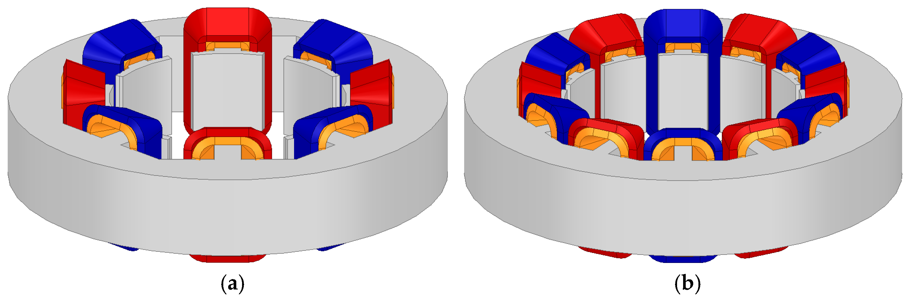
The 3-X rotor configuration and alternate windings used in this study are described in
Figure 2 and
Figure 3, respectively. Specifically, the 3-X 8 slots configuration is shown in
Figure 3a, and the 3-X 12 slots configuration is shown in
Figure 3b. The specifications for
Figure 3a,b are provided in
Table 1. Since an increased number of slots complicates the manufacturing process, the number of slots was limited to S ≤ 4P. Additionally, according to VR resolver specification selection methods 1 and 2, the possible slot combinations are 4 slots, 8 slots, and 12 slots. In the case of the four slots configuration, the small number of slots makes it difficult to analyze the direction of eccentricity. For the eight slots configuration, as shown in (9) and (10), the difference in reluctance between windings wound in the positive direction and those wound in the negative direction is minimal, resulting in a small output signal. Therefore, the 12 slots configuration (S = 4P), which facilitates the most accurate direction estimation, was deemed the most suitable for applying the winding method proposed in this paper. Consequently, the analysis was conducted using the 3-X 12 slots configuration, as shown in the FEM analysis.
4. Advantages of the Proposed Winding Method
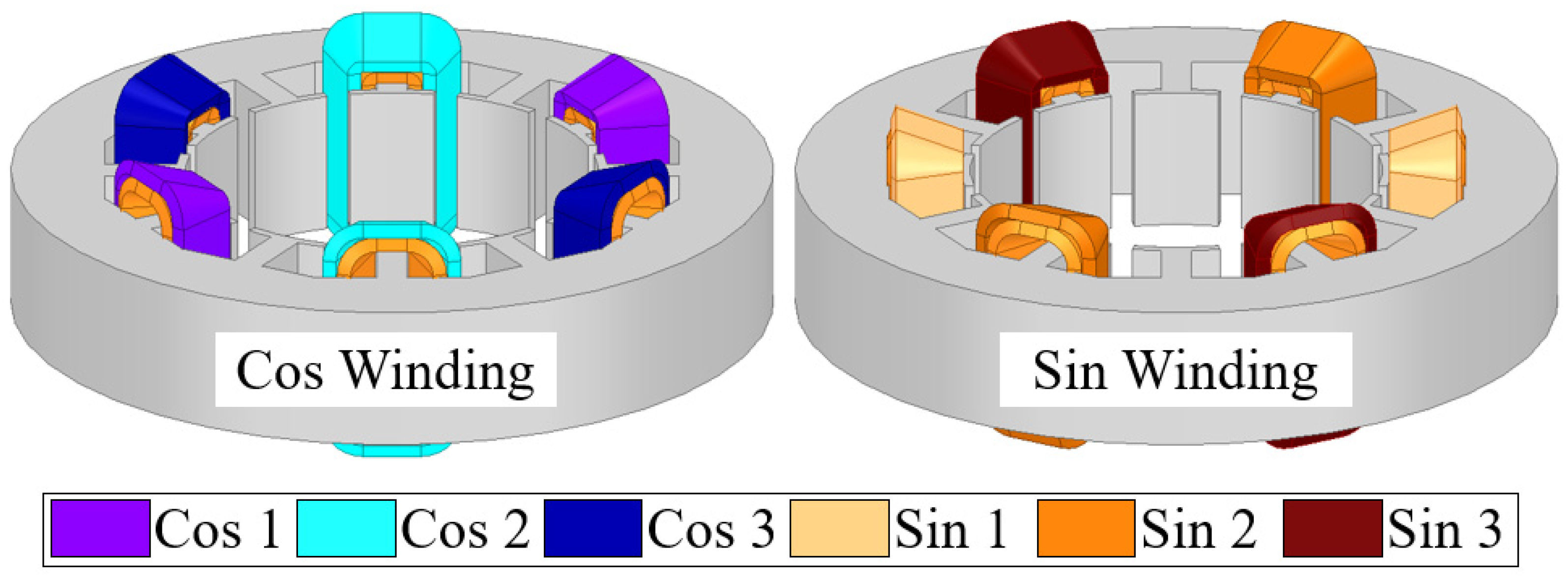
The proposed winding method produces the same output signal used to derive the position signal as the conventional winding method. However, the proposed method detects the output signal from each coil. In the configuration presented in this paper, with S = 4P, all sensing coils detect the same output signal. While sensing all 12 coils provides the best accuracy for direction estimation, increased segmentation also results in greater complexity. To address this, and to simplify the system while generating a sinusoidal waveform for the sensed signal, a method of sensing two coils together, instead of individually, was adopted, as shown in
Figure 4.
Therefore, the sin and cos windings each produce identical output signals with three coils, and the winding direction of the coils remains the same as the conventional method, as shown in
Figure 5. In the event of an open-circuit fault, the conventional winding method produces abnormal output signals. In contrast, the proposed winding method, which outputs exactly one-third of the signal, can generate a healthy output signal by applying an algorithm such as the one shown in
Figure 6. If the output signals of the sin winding and cos winding do not match, the α coefficient presented in
Figure 6 is applied. This process is repeated until the output signal aligns with the lookup table for healthy output signals. Through this iterative process, open-circuit faults can be temporarily corrected, as shown in
Figure 7a, and a healthy output signal can be derived, as shown in
Figure 7b.
5. Effect of EF Condition of IPMSM on VR Resolver
As shown in
Figure 8a, the IPMSM is in healthy condition, whereas in
Figure 8b, the IPMSM exhibits an SE (20%) condition. It can be observed that, under the SE (20%) condition, the center of the rotor and its rotational axis are shifted to the left relative to the center in the healthy condition. When an SE condition occurs in an IPMSM, the air gap length changes, as shown in
Figure 8b, causing electromagnetic variations and resulting in changes in magnetic flux. Under the SE condition of the IPMSM, the air gap length
is defined as follows [
8].
where
is the SE severity in the IPMSM,
is the rotational angular velocity of the rotor,
is the average air gap length, and
is the initial phase angle of the eccentricity. The inverse of the air gap length, which is named
, is defined as
Magnetic flux density B can be defined as
Therefore, when an SE condition occurs, distortion in the air gap magnetic flux distribution arises due to the changes in
. Furthermore, the occurrence of the SE condition, as shown in
Figure 9, leads to an increase in magnetic flux density due to the rise in
.
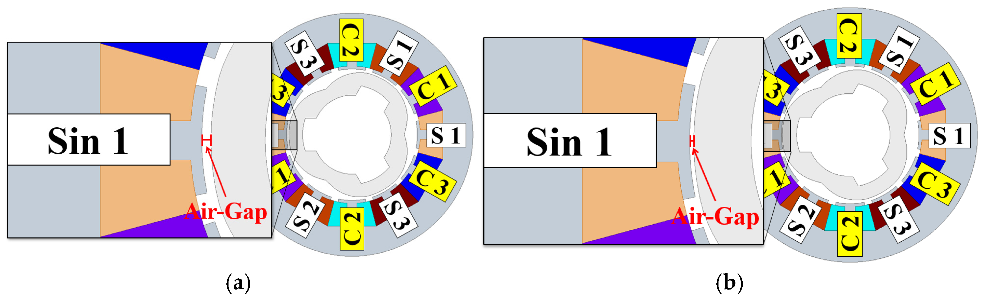
The air gap lengths of the VR resolver and the IPMSM are 0.355 mm and 1 mm, respectively. Since both devices share the same shaft, the eccentricity length of the VR resolver is set equal to that of the IPMSM, as shown in
Figure 10. Consequently, the distortion in the magnetic flux distribution is more pronounced in the VR resolver, as shown in
Figure 11.
As shown in
Figure 9b, the VR resolver of the IPMSM under the SE condition is shifted to the left compared to the VR resolver of the healthy IPMSM. Under the SE condition of the VR resolver, the air gap length is defined as
where
and
are the maximum and minimum values of the air gap length,
is the number of salient poles, and
is the SE condition severity in the VR resolver.
Therefore, when an SE condition occurs in the VR resolver, it causes an electromagnetic change and affects the induced voltage. The influence of the IPMSM SE condition on the induced voltage of the VR resolver is discussed in detail in
Section 6.
6. Simulation Result
Using the conventional winding method and the proposed winding method, modeling for SE and DE was conducted in the Sin 1 direction, as shown in
Figure 9.
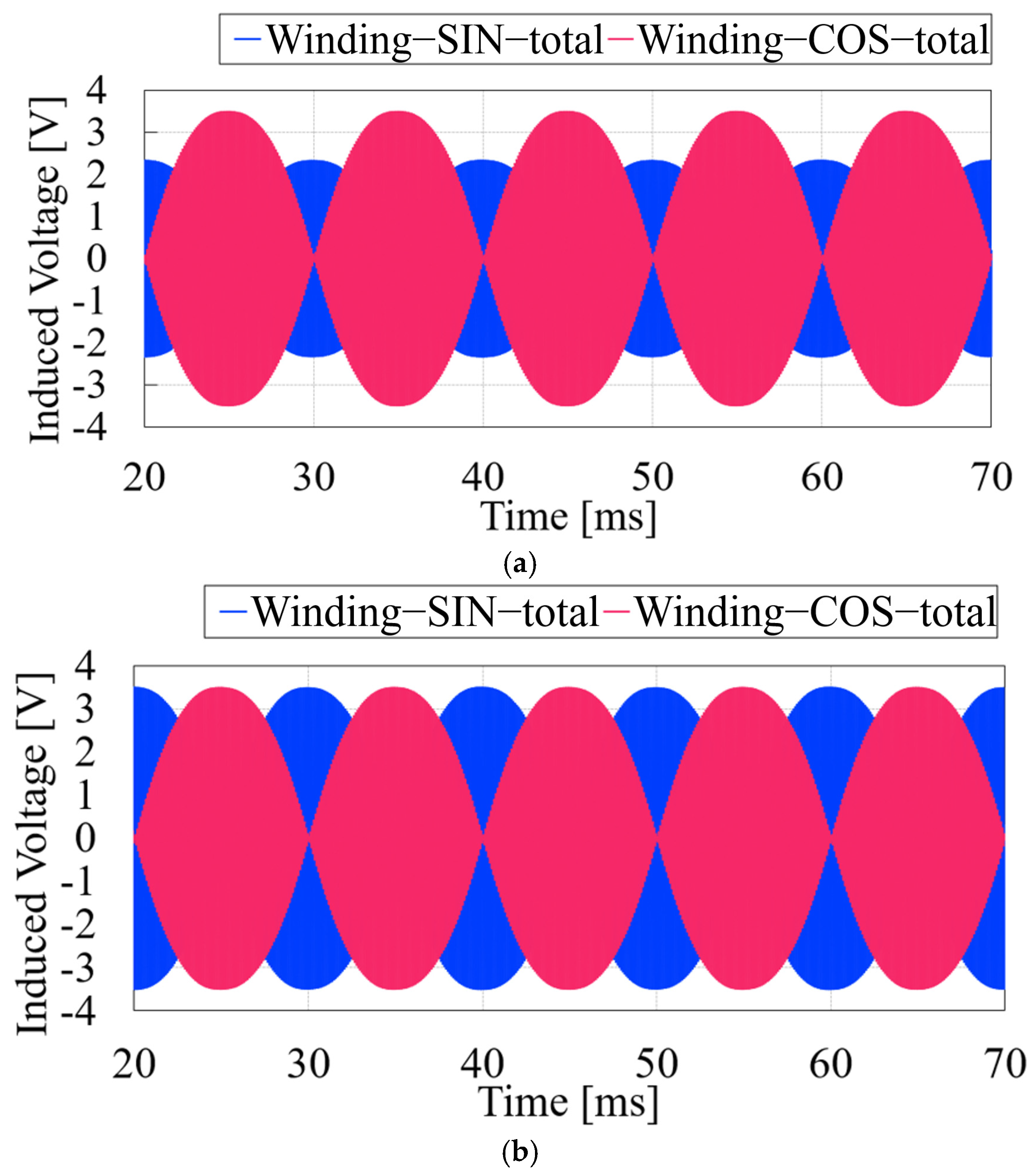
Figure 12 shows the output signals of the VR resolver in healthy, SE (20%), and DE (20%) conditions using the conventional winding method. Under the healthy condition, a maximum of 3.50 V is observed. In contrast, the SE (20%) condition shows a 22% increase to 4.24 V, and the DE (20%) condition shows an 18% increase to 4.22 V.
As shown in
Figure 13a, in the VR resolver with the proposed winding method under healthy conditions, the output signals for Sin 1, 2, 3, and Cos 1, 2, 3 are consistently 2.34 V. However, under the SE (20%) condition shown in
Figure 13b, the Sin 1 output signal significantly increases to 5.62 V, while under the DE (20%) condition, it increases to 5.57 V. Consequently, compared to the healthy condition, the output signal of the VR resolver increases by approximately 140% under the SE (20%) condition and by about 138% under the DE (20%) condition.
Due to eccentricity, the air gap length is most reduced in the Sin 1 winding, resulting in the largest increase in the Sin 1 output signal. This makes it possible to identify the occurrence and specific location of both SE and DE. Analyzing the increased output signals enables the effective identification of eccentricity occurrence and its precise location.
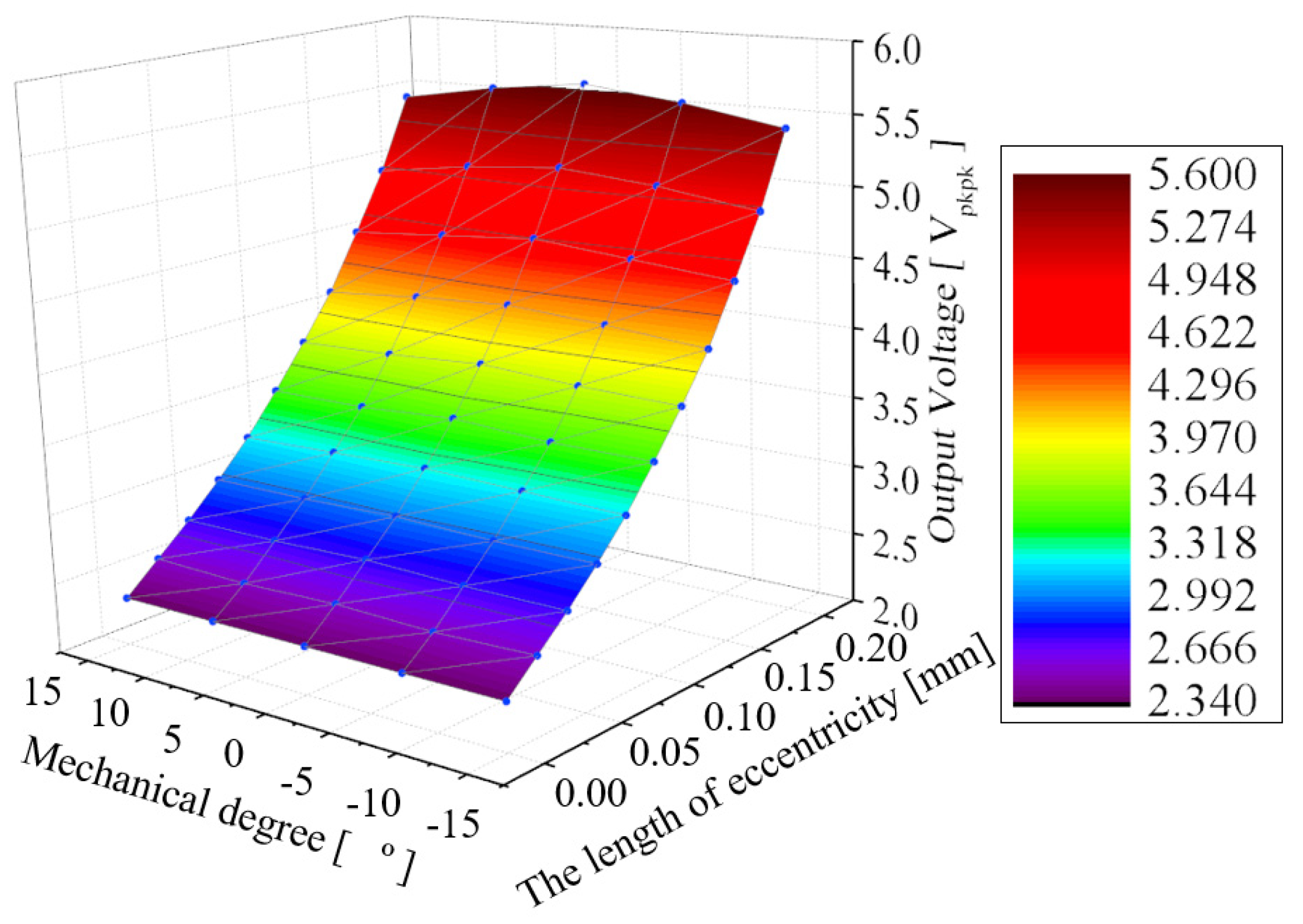
As shown in
Figure 14, with the output signals of the resolver in the SE condition, severities of 10%, 15%, and 20% in the IPMSM are presented in the table. At a 10% SE condition, 3.50 V was obtained, representing a 49.57% increase compared to the healthy condition. At a 15% SE condition, 4.40 V was derived, indicating an 88.03% increase over the healthy condition. At a 20% SE condition, 5.62 V was derived, indicating a 140.17% increase over the healthy condition. Therefore, the new winding method is advantageous for diagnosing SE conditions as it responds more sensitively to SE in the IPMSM compared to conventional winding methods.
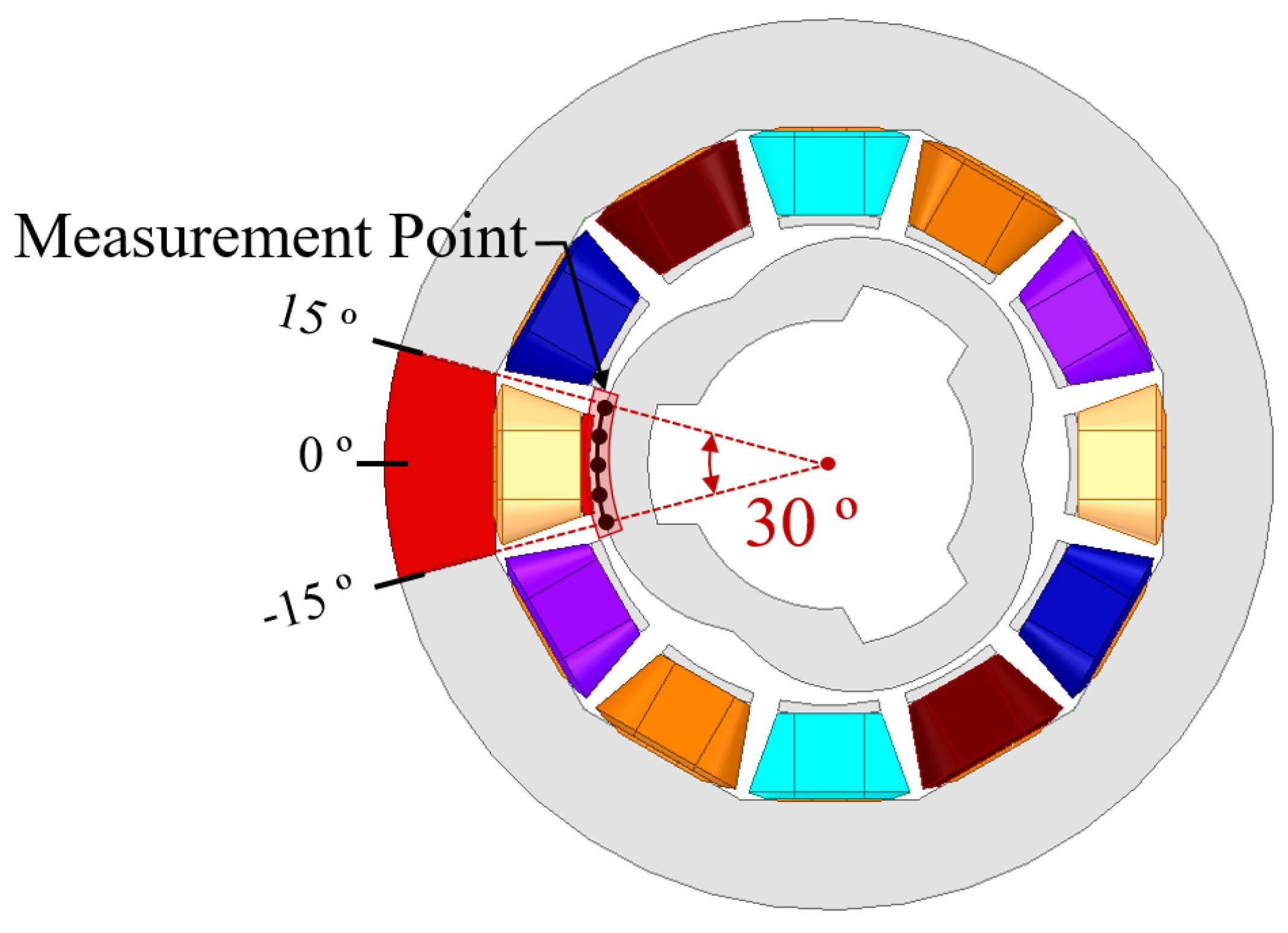
Additionally, as shown in
Figure 15, simulations were conducted based on the severity of bias at five points within the areas where the output signal of a single slot could be the largest.
As a result, as shown in
Figure 16, it was observed that the magnitude of the maximum value decreases as the distance from 0 degrees increases. Additionally, the output signal of adjacent slots tends to increase. Therefore, based on these trends, it is possible to determine the direction of the EF not only at 0 degrees but also at 15 degrees.
7. Conclusions
Figure 17 shows the fault diagnosis algorithm derived by analyzing the characteristics of the fault of the VR resolver.
where
represents the maximum value of the envelope-processed output signal,
is a lookup table of the maximum value of the envelope-processed output signal in a healthy condition,
ov is an error for the envelope-processed output signal, and
ov indicates the error of the envelope-processed output signal in manufacturing tolerances and mechanical assembly in the healthy condition.
Through (16), ov is derived by comparing the magnitude content of the output signal and the healthy condition lookup table. Additionally, the errors hv due to manufacturing tolerances and mechanical assembly errors in the healthy condition are compared and analyzed to diagnose the fault. The error caused by manufacturing tolerance and mechanical assembly is defined as 4%. Therefore, the presence of an EF fault, whether SE or DE, is diagnosed by using the maximum amplitude of the output signal. Additionally, experimental errors should be considered, and the margin for the healthy condition should be experimentally analyzed before deriving the error table for the healthy state.
Reliability is a critical factor in mobility applications. Thus, fault diagnosis is essential to improving reliability. Previous studies have performed fault diagnoses using VR resolvers. VR resolvers generally have a smaller air gap length compared to motors, which allows the output signal to respond more sensitively, offering the advantage of a more effective fault diagnosis. Furthermore, since the magnitude of the output signal does not change with speed, VR resolvers can be applied in environments with significant speed fluctuations. In this study, the coil method of the VR resolver was modified for fault diagnosis, enabling a more detailed analysis of eccentricity. The VR resolver winding method proposed in this paper enables a more accurate diagnosis of eccentricity compared to conventional winding method, offering insights into the direction of eccentricity. Additionally, the proposed method enhances the robustness against winding faults compared to conventional approaches, thereby contributing to an even higher level of reliability. For reliability, determining the presence of eccentricity is more important than identifying its type. This paper demonstrates through simulations that both SE and DE lead to an equivalent increase in the maximum value, depending on the severity of the eccentricity. Therefore, the proposed method offers the advantage of easily detecting the presence of eccentricity, regardless of its type.


