Article

Fault Injection Tool for FPGA Reliability Testing: A Novel Method and Discovery of LUT-Specific Logical Redundancies

1
Faculty of Electrical and Computer Engineering, Cracow University of Technology, Warszawska 24, 31-155 Kraków, Poland
2
Department of Measuring Information, and Technologies, Lviv Polytechnic National University, Bandera Str. 12, 79013 Lviv, Ukraine
3
Department of Information and Computing Systems and Control, Faculty of Computer Information Technologies, West Ukrainian National University, 46009 Ternopil, Ukraine
*
Author to whom correspondence should be addressed.
Electronics 2025, 14(23), 4600; https://doi.org/10.3390/electronics14234600
Submission received: 1 October 2025 / Revised: 10 November 2025 / Accepted: 13 November 2025 / Published: 24 November 2025

Abstract

FPGAs are well suited for prototyping complex digital systems for industrial and research purposes, as well as for the practical application of artificial intelligence (AI) methods in industrial autonomous control, automotives and space. FPGAs serve as platforms for inferring based on AI algorithms. In recent years, an increase in FPGA system applications with respect to advanced computing functions for physical and chemical research in space has been observed. Research on the reliability of applications operating in the above-mentioned areas exposed to radiation is of particular importance. Testing applications implemented on FPGAs requires the development of new methods that differ significantly from those intended for Application-Specific Integrated Circuits (ASICs). The FPGA logic is realized by SRAM-Based Look-Up Tables (LUTs). SRAM is relatively susceptible to single-event upsets (SEUs) generated by cosmic radiation. The existing fault injection (FI) tools do not model the faults generated by SEUs in SRAM-based FPGAs precisely enough. New FI tools are crucial for evaluating newly developed FPGA-specific tests. Thus, we developed a new tool that uses an accurate SEU model in LUTs. This new tool is written in Perl, and its tasks are to inject faults into the structural VHDL description and to control the CADENCE simulator. The novelty of this solution is that the tool models SEUs by modifying the logical functions generated by the LUTs. Furthermore, in this way, stuck-at faults at the LUT inputs and outputs can also be modeled. This method involves modifying the “INIT” parameters in the structural VHDL. Our tool was evaluated using several test programs, and a high fault coverage (FC) of 94.76% was achieved. This tool can be used to examine any LUT-based FPGA technology regardless of its implementation age. Moreover, during our research, a new mechanism of generating so-called logical redundancies caused by the injection of single faults in LUTs was discovered. This is a side effect of FI in LUTs, which makes it impossible to achieve 100% fault coverage of applications implemented on FPGAs. The mechanism of this phenomenon does not occur when injecting traditional stuck-at faults.

1. Introduction

The applications of SRAM-based FPGAs in safety-critical applications, e.g., space or automotives, are constantly growing due to their flexible online reconfigurability, fast time-to-market [1], and large and advanced logical resources offered by the Xilinx Versal family (Xilinx-San Jose, CA, USA). Real-time multiprocessor systems, microcontrollers, and interface adaptations can be implemented on FPGAs [2,3,4], both in space and automotive technologies. According to the current trend, applications based on Convolutional Neural Networks (CNNs) are increasingly being used in safety-critical space or automotive applications [2,5]. The Xilinx Versal FPGA, designed specifically for inference using artificial intelligence algorithms, is also implemented in SRAM-based technology.

1.1. Problem of Interest

SRAM-based FPGAs are quite susceptible to single-event upsets (SEUs) generated by cosmic radiation [3,6,7]. Reliability is crucial in applications exposed to cosmic radiation. Hence, when an FPGA is used in space, autonomous control [5], or other critical missions, evaluating its sensitivity to SEUs is important.
Traditional stuck-at fault models are insufficient for representing SEU-induced faults in SRAM-based FPGAs. Specifically, SEUs can generate phenomena such as a single-bit flip in the configuration memory, which can modify the FPGA’s functionality. Thus, despite the fact that SEUs are classified as a transient effect in ASICs, they can induce a permanent fault in an SRAM-based FPGA. SEUs can also cause faults that manifest themselves in the same way as classic stuck-at faults [7,8]. However, this indicates that only using the stuck-at model for FPGAs leads to poor fault coverage. In ASICs, SEU phenomena are only transient and disappear after a specified period of time. Therefore, unlike ASICs, SEU effects cause malfunctions in the system implemented in an FPGA until reprogrammed [3,6,7].

1.2. Fault Injection Literature Review

There are several techniques for evaluating the sensitivity of FPGAs to SEUs, such as physical radiation experiments, fault injection by simulations, or emulation [9].
Physical fault injecting using accelerated particles or a laser beam produces the same effects as sending an FPGA into space [10,11,12,13]. Physical fault injection methodology is limited because it cannot be applied in the initial design stage. Moreover, the cost is high, and a physical prototype is required.
Simulation-based fault injection is a technique in which the Hardware Description Language (HDL) of the Design Under Test (DUT) is simulated, and the faults are injected through software [14,15]. These methods can be based on the commands of simulators or saboteurs [14]. Simulation-based techniques enable quick verification of an initial prototype [16,17]. However, they can be extremely time-consuming in cases of complex circuits and require powerful workstations [12].
Emulation-based approaches allow speeding up a fault injection campaign and prototype evaluation at the initial stage. However, they require interaction with hardware because the model is modified by adding additional logic, and the development board is connected to a host computer [13,18,19,20,21,22].
Circuit modification methods are proposed in [14,19,23]. In these methods, faults imitating SEUs are injected into the user memory of SRAM-based FPGAs. A tool that modifies the HDL description is proposed in [15]. This tool injects faults by inserting faulty HDL primitives within a gate-level netlist. Unlike this solution, we do not change the primitives described in HDL (elementary subcircuits optimized for the hardware structure of a specific FPGA family). We only change the parameters that determine the LUT functions through software. The most important difference is that this publication does not analyze the effects of these changes at all, i.e., the generation of different logical functions by the LUT than those intended. According to a simulation based on the approach considered in [24], faults are injected into different parts of the microprocessor system, such as kernel memory, middleware memory, application memory, and FPGA registers. Munoz [14] proposed a simulation-based method where faults are injected into registers of a simple application, such as a counter. This is a low-cost solution that can be used to test the fault tolerance of FPGA-implemented systems. However, this method focuses on modifications to the SRAM configuration bitstream. It does not analyze the SEU effects in LUTs.
To improve the execution time and fault coverage results, modern emulation-based techniques using the dynamic partial reconfiguration of an FPGA are currently attracting substantial attention [16]. The partial reconfiguration of FPGAs makes the FI injection quicker, because only the appropriate bitstream frames implementing the modified (faulty) fragment of the system are downloaded [25]. The authors of [16] propose an innovative methodology that does not address SEU, but rather Single Event Transients (SETs). Their research aims to estimate fault tolerance. Nevertheless, we can consider a comparison of this method with the one proposed in this paper. Bit flipping simultaneously occurs on the entire 16-bit frame, which is performed in [16]. Note that partial reconfiguration operates on frames of a specific bit size. After improving the design of [16] to enable single-bit flipping, this method can be considered as an alternative to our simulation-based method. However, the computation of LUT addresses within the bitstream is complex. Masking single bits may prove difficult or infeasible here. The authors of [16] even claim that, in their system, it is not possible to determine exactly which sub-address of the Configurable Logic Block (CLB) implements a user function. This is the main disadvantage of their method. Another drawback is that the so-called sensitive areas of the configuration frame found by the authors do not only contain user logic, as only 72% of the bits in the configuration frame are related to the user logic. In the case of other similar solutions [18], the ratio of sensitive bits varies from 0.194% to 11.18% depending on the user application implemented on an FPGA [18], or it ranges from 75.87% to 83% depending on positions [20]. A slightly different solution [26] involves reaching the sensitive area by constraining the user’s application in a placement block. The authors of [26] estimate that only 15.5% of all injected faults resulted in application malfunction. Therefore, the disadvantage of such solutions [18,20,26] is the low ratio of the sensitive bits. Another work [19] performs FI merely according to the user’s FPGA memory, and it proposes a circuit modification. However, it does not model faults in LUTs.
The emulation-based solution presented in [26] saved time by placing the control logic in hardware. Python scripts that automatically generate the FI system in an efficient way were applied. The sensitive area of the user design on the FPGA was determined, and configuration bits were accurately injected into this area. The idea presented in [8,26] is similar to ours: Namely, the goal is to precisely inject faults bit by bit. These methods are based on emulation and are much more complex than ours. The essential features of the most widely used methods are summarized in Table 1.
Some solutions use the Internal Configuration Access Port (ICAP) to inject faults during the dynamic partial reconfiguration [31]. Other more sophisticated ideas use the Xilinx MicroBlaze processor to control the ICAP [32,37]. This solution rapidly collects FI data. The ICAP-based solutions can speed up the FI campaign by up to eight times [32]. The drawback of emulation-based solutions is often random fault injection [1,32]. This means that not all possible faults are injected, and their locations are random [21]. In contrast, our tool injects faults into all possible locations in the LUTs.
Applying partial reconfiguration techniques, Automatic Test Equipment (ATE) is typically implemented in the static part of the FPGA. This allows testing several DUTs concurrently in different dynamic partial regions [32]. It should be noted that only a small percentage of FPGAs support partial reconfiguration. Known and currently available methods for fault injection in FPGAs for research purposes can emulate logic faults in FPGA prototypes by manipulating the contents of their configuration memory (CM) online [23]. The tool presented in [23] can inject faults into registers, LUTs, BRAM, and LUTRAM on the netlist level. The method in [23] utilizes the technique of “redback”, “modification”, and “writeback”. The significant limitation of this method is the need to repeat the entire process to inject every single fault. De Oliveira in [13] investigates the performance and reliability of the RISC-V Rocket processor implemented on an SRAM-based FPGA by applying both physical fault injection and the emulation of faults. The sensitivity of this processor to radiation effects is similar to other soft processors implemented on FPGAs [38]. On the other hand, in [32], Wilson revealed that Rocket Chip is more sensitive than other soft processors explored in previous works. Sari, in [33], presented the fault injection platform developed as a CAD framework to analyze the effects of SEUs in soft processors implemented on Xilinx FPGAs. This platform estimated the sensitivity of processor components to soft faults in the configuration frame. Alternatively, various SEU mitigation techniques, such as hardware redundancy and scrubbing, were considered for the reason of SEUs [13].

1.3. The Research Gap

We identified the research gap, which is described in this section. Namely, there is no simulation-based tool described in the literature that addresses SRAM-based FPGA platforms and precisely models SEU faults in LUTs, as demonstrated by physical studies [7]. Moreover, existing FI tools do not model all possible SEUs effects in LUTs. Current new tools allow for fault injection by modifying the bitstream or connection list after synthesis or after implementation [1]. Also, modern Xilinx tools, such as Xilinx Rapid Wright [39], and old FI tools, such as Jbits, are merely able to emulate logical faults at the level of the list of connections between cells [34]. Modifying the bitstream requires specific information from the manufacturer regarding the organization of configuration frames [23]. Lack of this information may result in damage to a device. Moreover, information about the bit format of the latest FPGAs is published reluctantly by manufacturers. All the above solutions do not reveal the details of the SEU phenomenon models in LUTs as presented in [4,8]. They only report the results of their occurrence. Most modern FPGA-based fault injection (FFI) tools focus on emulating random fault injections at the configuration bitstream level, regardless of the designer or researcher’s intentions [40]. Similarly, a tool proposed in [17] injects faults into registers and other components of the RISC-V processor. This solution is based on well-known simulators, such as Questasim, Vivado Isim, or Verilator. However, it is not adapted for SEU modelling but is intended to evaluate the reliability of the processor working in Internet-of-Things applications. Developed by Cadence Design System and Mentor Graphics, the Universal Verification Methodology (SE-UVM) enables modelling single-bit or multi-bit flip faults exclusively at the LUT’s output on signal paths, as well as stuck-at faults at any locations within the DUT [41]. The achieved fault coverage level by new tools using this methodology does not even exceed 75,17% for some DUT blocks, much simpler than processor cores [36]. Another well-known microprocessor fault injection tool, such as MiFIT or GOOFI, injects faults into specific and general-purpose registers. On the other hand, the Naken-FIM tool injects faults into any locations within memory and registers [27]. These tools are primarily dedicated to testing ASICs vulnerability, and none of them model all possible SEUs effects in LUTs of FPGAs, as mentioned above.

1.4. Contribution and Scope of This Paper

This paper presents an analysis of the newly developed simulation-based fault injection (FI) tool, which serves to test the reliability of applications implemented on FPGAs. This new tool can deterministically inject faults into precisely defined locations in FPGAs. We define precision as the repeatability of injecting faults into specific locations in LUTs. The precision of our tool, determined in this way, is 100%. Due to the precision of fault injections, we either know exactly or can easily determine what subcircuit each fault was injected into. This information is included in the fault description shown as an example in Figure 6. Moreover, we can easily observe how each deterministic fault modified a given subsystem. The schematics of modified subcircuits can be displayed using conventional FPGA tools, or they can also be drawn by a designer.
The main task of this tool is to model the same effects inside FPGAs as induced by the physical phenomena of the SEU [2,8]. Our new tool is based on the accurate SEU model in the LUT proposed in [4,8]. This tool was developed primarily to evaluate the quality of a bijective program intended for the functional test of microprocessor cores. High fault coverage was achieved [4]. The assumption of our method is fault injection into all possible locations in the LUTs forming the processor core. Hence, our method can be called exhaustive FI. Our tool is helpful for creating test programs dedicated to microprocessor cores, and as a good test program, it should detect all possible faults introduced into the core. Because faults are injected deterministically and precisely, the test program designer can easily improve their program by analyzing the architecture of the logic generated by the LUT after fault injection. Such analysis helps in finding test vectors that detect specific faults.
The proposed tool can also be used for testing the fault immunity of newly designed circuits. Individual blocks can also be tested separately during the design stage. The designer can specify the scope of fault injection in terms of VHDL description lines by writing the lut.init file, as shown in Figure 6. A fault injection experiment on just one block will last substantially longer. Only when the project is finished is it a good idea to inject faults into the full scope of its VHDL description.
Our new tool can be used to assess the SEU susceptibility of any system implemented on an FPGA. Only conversion to structured VHDL or Verilog is required. This conversion is always performed using conventional Xilinx or Altera tools during the design process. This ensures that structured VHDL or Verilog will always be available, even if the system is described at a different level of abstraction (behavioral and RTL). This allows us to apply this tool to any digital circuit implemented on an FPGA, such as the following: DSPs, digital filters, receivers/transmitters, or digital automata; not exclusively soft processor cores; etc.
Another important contribution is that our tool can also be used to inject faults into the structured VHDL description of the latest FPGA families, such as Xilinx Versal ACAP. These families contain six-input and five-input LUTs, for which their logical functions are also determined using the INIT parameter. In comparison to the LUTs composing older FPGA families, the difference is that the parameters determining the LUT functions can have larger numerical values in newer FPGA families than those in older ones. This poses no problem for our script. Therefore, our tool will remain valid as long as the FPGAs use SRAM-based LUT technology.
The script developed by us injects faults into the LUT that may cause permanent (until the FPGA is reconfigured) functional faults in the tested processor. In this way, connection faults can also be modelled as stack-at on the inputs and outputs of the LUTs. Our new tool is flexible because it can also inject faults into Verilog and System Verilog descriptions after slight modifications. It can also cooperate after minor modifications, as described in Section 4.4, with other known FPGA simulation tools built in the Vivado or Quarus Prime environments, apart from the CADENCE VHDL simulator. As mentioned before, in the literature review section, simulation-based fault injectors have the advantage of being inexpensive. Furthermore, we offer a free FI tool to the readers.
During experiments with fault injection into an FPGA, the phenomenon of fault masking was discovered. It turns out that some of the injected faults generate redundant Boolean expressions. This means that after a specific fault was injected, the LUT may generate a different function with redundant expressions, but the logical value of this function is identical to the original one.

1.5. Paper Organization

This paper is structured as follows: Section 1.1 introduces the reader to the problem. Section 1.2 presents the literature review, and the known methods are compared. Section 1.3 points out a research gap. Section 1.4 presents the contribution and scope of this paper. Section 2 provides the reader with background information. In Section 3, the new fault models developed by the authors are explained and shown with detailed examples. Section 4 describes the functionality and main tasks realized by the new FI tool. Section 5 aims to draw the readers’ attention to the fault-masking phenomena that occur during fault injection into LUTs in FPGAs. In Section 6, the advantages and disadvantages of the proposed tool are discussed. Finally, the conclusions and future work are presented in Section 7.

2. State of the Art

Particularly useful features of FPGA technology are as follows: flexible configurability and fast time to market at the prototype development stage. This technology makes it feasible to dynamically adjust or update implemented functions with respect to varying tasks, particularly through partial online reconfiguration without the need to stop the operation of all system components [19]. FPGAs can implement complex multiprocessor systems cooperating with DSP blocks, in addition to application and real-time processors, integrating with AI engines. As AI technology enters all the above-mentioned industries, FPGAs have become particularly useful due to the ease of implementing AI solutions [5].
Electronic devices are sensitive to ionizing cosmic radiation, which can even lead to permanent damage, classified as Single Event Burnout (SEB) or Single Event Latch Up (SEL) effects. A different class includes non-destructive phenomena such as Single Event Transient (SET) or Single Event Upset (SEU). The FPGA components that are particularly susceptible to cosmic radiation are SRAM-based Configuration Memory (CM) [2,42]. SEU in CM can alter the connections within the FPGA’s logic, as well as the settings and content of LUTs. This leads to the incorrect generation of logical functions. Therefore, SEU can alter the expected behavior of the high-reliability system implemented on an FPGA, which can cause catastrophic results. For this reason, various techniques have been developed to mitigate the effects of SEUs. To assess the need for these mitigation techniques, research on the vulnerability of systems implemented on an FPGA to SEUs is carried out [28,29]. These works consider injection and detection faults in an FPGA and study the operation of the system under test.
The need for FPGAs in safety-critical systems increases significantly with the development of space technologies and autonomous control systems in general and automotive industries [5]. The reliability requirements for each of these industrial areas are defined by the relevant standards and regulations. In aerospace engineering, electronic components and systems must operate correctly under extreme conditions and for extended periods of time, which is achieved with rigorous testing and hardware redundancy. Due to increased cosmic radiation, SEU phenomena in FPGAs and SET in ASICs occur more often. Testing both the processors and logic in ASICs and FPGAs is essential. Due to the use of hardware redundancy, systems that are not currently used are tested at intervals specified by the relevant regulations for this field. The reliability requirements for autonomous industrial control systems, in turn, focus on achieving continuous, error-free operation through redundancy, robustness, rigorous testing, and adherence to stringent standards in this field. Other reliability requirements apply to automotive systems. They focus on ensuring that components and systems function correctly and safely throughout the vehicle’s intended service life despite harsh conditions. All electronic components are tested during the manufacturing process, using methods based on regulations in this field. Finally, in the field of scientific research on effective test programs, equipment reliability, as well as resistance to external influences and methods for evaluating innovative solutions, play a key role. Effective test programs are crucial in all the above-mentioned areas. To develop and evaluate test programs that achieve 100% fault coverage (FC), precision evaluation tools are necessary. Our Perl script is one of the proposed tools.
The fault injection methods are as follows: hardware-based, emulation-based, and simulation-based radiation experiments (as described in the Introduction). Concerning the emulation methods, it should be emphasized that the proposed method differs fundamentally from bitstream manipulation, because it does not manipulate the bitstream at all. In contrast, it modifies the INIT parameters at the structural level of the HDL description, as described and illustrated by examples in Section 3. The emulation-based approaches often encounter the following problem: Sometimes, after injecting some configuration bits, the subsequent injection process will cause the DUT to keep making errors [18]. The undeniable advantage of the emulation methods is their speed. However, their precision leaves them considerably below 100% accuracy, unlike our method. Moreover, many of the emulation methods described in this paper rely on random fault injections. In contrast, our method is classified as exhaustive FI. Our FI method should be considered simulation-based. However, it fundamentally differs from all other methods of this type found in the literature. None of the methods described in Section 1.2 model SEU faults in LUTs according to the physical mechanism of their generation as single-bit flips. Instead, only stuck-at faults are injected at the LUT inputs and outputs or at other locations in the FPGA logic. These models are insufficient because they do not model the changes in logical functions generated by the LUT as a result of SEU. When the functionality of FPGA logic is changed, it most often leads to malfunctions, which can be more complex than simply shortening some signals to 0 or 1. Namely, new, unintended, and unnecessary logic functionality may even appear, and vice versa, useful logic functionality may be limited. In summary, without the trustworthy modelling of faults in LUTs (for example, using our tool), the aforementioned changes to the functions FPGA logic will definitely be incomprehensible. However, test programs that only detect stuck-at faults are ineffective and can result in falsely inflated fault coverage (FC).

3. Proposed SEU Fault Models

In this section, we explain the SEU fault models in the LUTs developed by us [4,8]. We model faults by modifying the values of parameters that determine the functions generated by the LUTs. The modification of the “INIT” parameter value in VHDL leads to the generation of a different logical function by the LUT than the desired one. We modify these parameters to trigger a single bit-flip at a time. Such faults are more difficult to detect by each dedicated test program. By altering the numerical value of the “INIT” parameter at several positions, multiple bit-flips can also be generated.
As mentioned in [8], PicoBlaze, described in structural VHDL, optimally uses the resources of a dedicated FPGA. We noticed that the structural VHDL description at the level of Xilinx primitives, such as LUTs, allows for the precise injection of intended faults. Structural LUT models allowed us to automate the process of fault injection. However, many digital systems are most often described at other levels of abstraction (behavioral and RTL) in VHDL or Verilog languages. Nevertheless, these can be converted to the structural level using Xilinx implementation tools.
Injected faults manifest themselves as architectural changes in specific processor subblocks, reflecting the impact of SEUs on the functions implemented by those sub-blocks. By modifying the LUT function, it is also possible to model stuck-at faults at the LUT inputs and outputs, as explained in Section 3.2. Subsequently, detailed examples illustrate the mechanism of generating functional faults by SEUs in the blocks of the PicoBlaze processor core, as well as stuck-at faults. In all examples, the values of the logical function generated correctly by the LUT are marked in green, while incorrect values are marked in red. In the columns of the truth tables described by the inputs of a given LUT from I0, I1, I2, …, all combinations of input arguments are listed. The first columns, described as “Out”, present the correct LUT logical functions in binary form. The next columns present these functions in hexadecimal form. The next “Out” column presents incorrect values after changing the INIT parameter, with the error marked in red.
Based on the structural HDL description, modelling the following types of faults in an FPGA is feasible:
  • Incorrect logical functions generated by LUT, stored in the configuration memory;
  • Faults stuck at the inputs and outputs of the LUT;
  • Address decoders of memory and LUT faults.

3.1. Example 1: Logic Group Fault Model

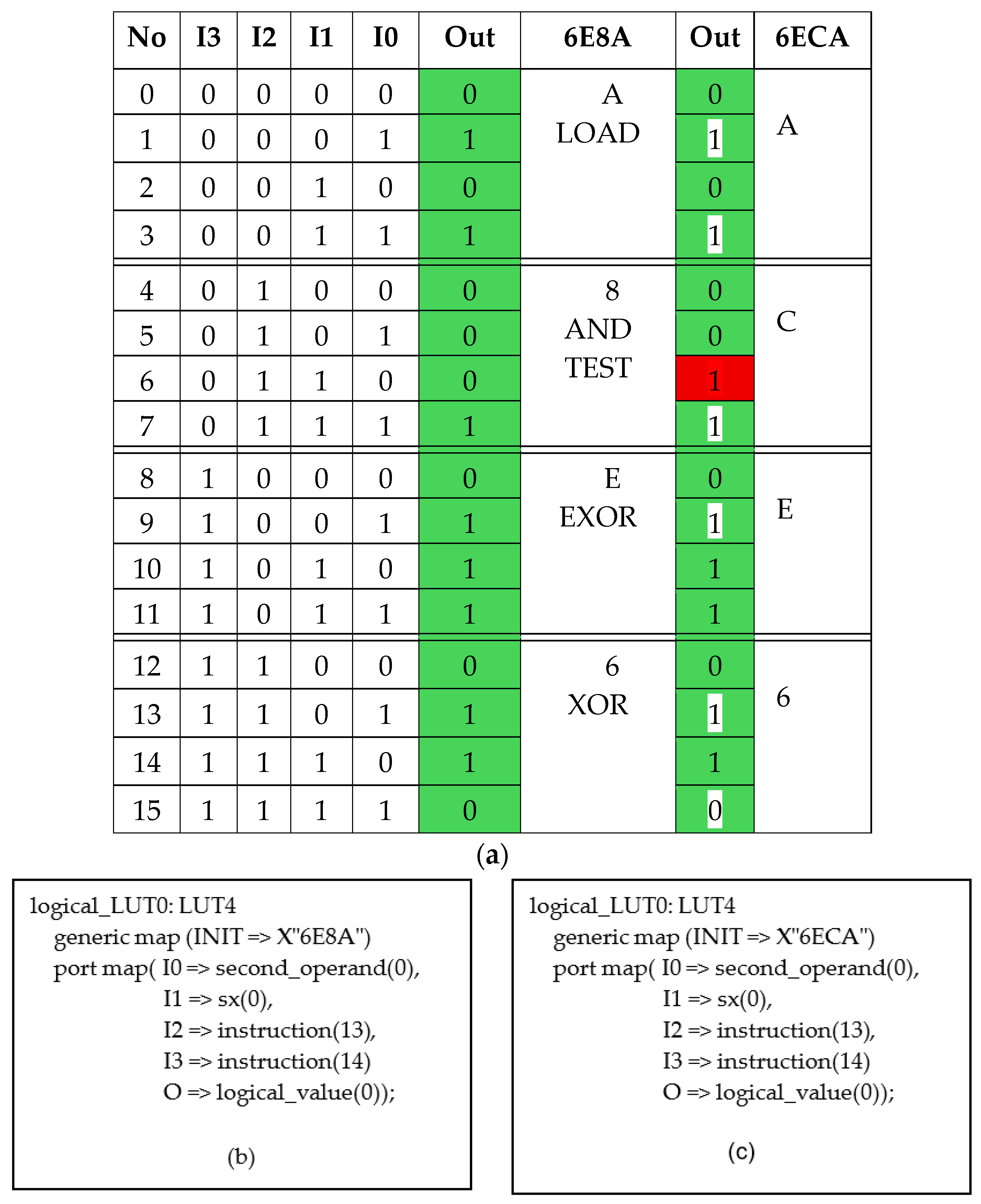
The architecture of the logical instruction block of PicoBlaze is shown in Figure 1. All these instructions fetch two operands. The output multiplexer can switch instructions. Let us consider the case where the INIT parameter in the VHD code describing the function of the four-input LUT obtains the value of “6E8A”. By analyzing the truth table in Figure 2a, it can be observed that digits “6”, “E”, “8”, and “A” generate the XOR, NXOR, AND (TEST), and LOAD functions, respectively. More detailed information is provided in Table D-1: “PicoBlaze Instruction Codes” [43].
The first example of the novel fault model is presented in Figure 2. The corresponding truth table for both correct and incorrect INIT parameters is presented in Figure 2a. The input signals I0-I3 for the logical LUT refer to the specific bits of the instruction opcode in Figure 2b. The generated logical function is determined by the initialization of the parameter INIT specified as X”6E8A”, where, for instance, code “8” generates “AND” and “TEST” instructions, as is shown in Figure 2a. The SEU-induced fault in an LUT usually manifests itself as a modification of a single bit value inside the LUT, thereby modifying the Boolean function generated by the LUT. From Figure 2a, it can be seen that the logical functions “AND” and “TEST” of the assembler instructions were modified into some unintended logical functions.
The structural VHDL code of the logical LUT initialized by the correct INIT parameter is shown in Figure 2b, whereas the code with the incorrect parameter is visible in Figure 2c.

3.2. Example 2: Stuck-At Fault Model

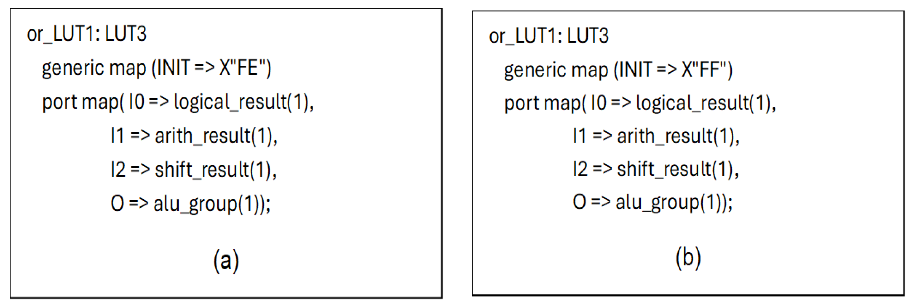
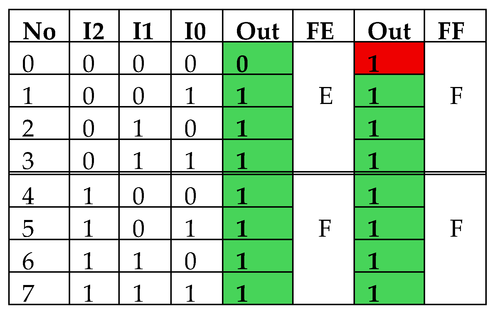
Stuck-at faults can also be modeled at both the inputs and outputs of the LUT by changing its logical function. This modification can be interpreted as meaning that the logical function is still correct. Only stuck-at-0 or stuck-at-1 faults occurred at some inputs or outputs. An example of the correct VHDL description of ALU OR LUT and with a stuck-at-1 fault at one or more inputs (or also outputs) is presented in Figure 3. The initialization parameter, INIT, of the LUT is modified, as seen in Figure 3b.
The truth tables presenting the fault-free LUT code (“FE” column) and the stuck-at-1 faults (“FF” column) at the inputs or the output are included in Figure 4.

3.3. Address Decoders of Memory and LUT Faults

The addresses of the RAM64X1S block memory are determined by the second_operand signal. This memory is used as scratch pad memory by instructions such as STORE sX (sY), STORE sX, AA, and FETCH sX (sY), FETCH sX, AA. The signal second_operand is formed as presented in Figure 5a,b. The correct function determined by the parameter “E4” is the following: O = I2I0 + !I0I1. After modifications of the parameter into “EC”, the faulty function is as follows: O = I1 + I0I1. After substitutions from Figure 5, we obtain the following: I0 <= Instruction(12); I1 <= Instruction(0); I2 <= sy(0). In the second operand register, we can observe, taking the PicoBlaze Instruction Codes into consideration, that instructions STORE and FETCH will not work, but every parameter that is set to “1” or bit 0 of the “Immediate value”, or when using some SHIFT instructions (SL1, SR1, …), will generate a wrong memory address on bit 0 of the address because, from the PicoBlaze description, ADDRESS(5:0) <= Second_operand(5:0); and Second_operand(0) = Instruction(0) or Instruction(12) and Instruction(0).

4. Proposed Fault Injection Tool and Environment Composition

The literature review reveals that there is a lack of a universal fault injection tool that is based on an accurate SEU model and is also open source software. Various methods of modifying the FPGA configuration bitstream, which often involve random fault injection, inherently lead to low fault coverage. Therefore, we decided to create a new fault injection environment based on the CADENCE VHDL simulator. Our new tool injects single-bit-flip faults in LUTs and stuck-at faults at LUT inputs and outputs by modifying the logic functions generated by the LUTs, as described in Section 3: “Applied SEU fault models”.
We also carried out test experiments to confirm the correct operation of our script. Towards the end of our tool development, additional scripts were written to check that none of the faults planned for injection were missing. Because our script saves all the fault descriptions and results generated by the DUT to a file, these helper scripts worked by comparing the output file with a reference file. The final test experiments involved injecting faults, using our tool, into the PicoBlaze processor core, as described in VHDL, using a simulator. The processor executed a test program or other application for each single fault injected and saved the generated results to a file. These experiments were aimed at checking the susceptibility of test and application programs to faults when running on a microprocessor implemented on an FPGA, as described in Section 4.3. The CADENCE VHDL simulator was used for the experiment, because it is one of the tools that allows for the simulation of the structural VHDL code of the processor.

4.1. Proposed Methodology of Fault Injection for the Specified FPGA

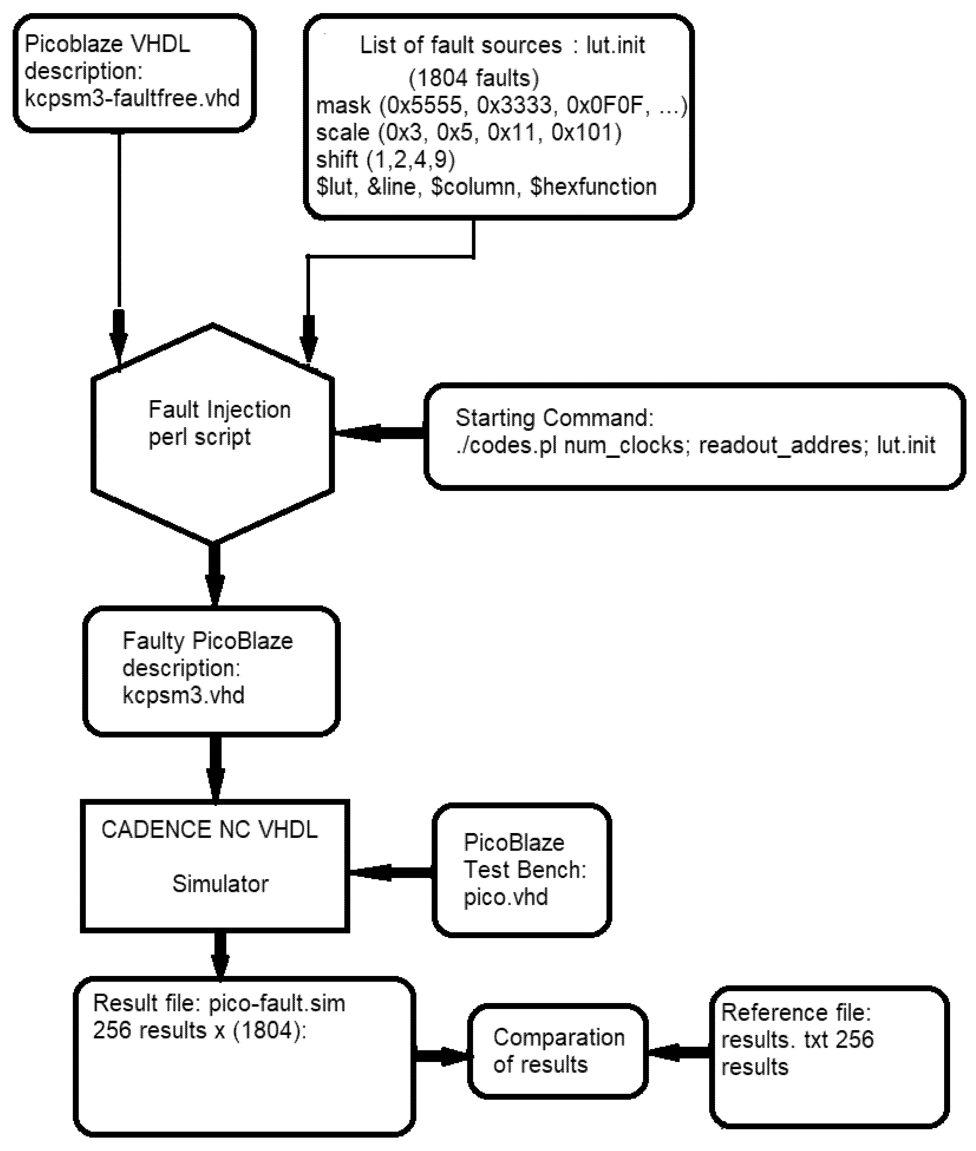
Injection of faults into the VHDL code is executed by the script written in Perl. All LUT resources used by the processor functional blocks are available in the VHDL code. The Perl script obtains a list of fault sources from the lut.init file. This list was created by the extraction of the PicoBlaze vhdl description (kcpsm3.vhd). The examples of several lines of the kcpsm.vhd and lut.init files are presented in Figure 6:
The meaning of the fields in the lut.init file is as follows: The Xilinx LUT model is coded with numbers 1, 3, or 4: the line number in kcpsm.vhd, where an LUT is placed; the column number in line; and the correct value of the parameter.
The operation of the script is as follows:
  • Using the basic programming logical “and” operation between the parameter value and the consecutive bit mask, each parameter is modified one by one. These bit masks are also scaled (multiplied by a scale factor) and shifted to obtain all possible 1-bit changes in the parameters stored as hexadecimal numbers. This is also carried out to fit these masks to the number of bits in which a given parameter is stored (4, 8, or 16 bits). This depends on the number of inputs of the LUT described by a given parameter (LUT1—2; LUT3—3; or LUT4—4 inputs). For instance, if inputs I2 and I3 are not used, the mask makes it possible to inject faults merely in the last four bits into the LUT.
  • The Perl script opens the kcpsm.vhd file and writes new faulty values of the INIT parameter in the line and column indicated in the lut.init file.
  • The Perl script automatically runs the simulator 1804 times using the CADENCE command. This means that the script will be executed until the entire list of fault sources is exhausted and all possible masking operations are completed.
  • The script takes input parameters such as a number of clock cycles required to complete the SEU simulation, an address of the last assembler instruction to read the results of the test program execution, and the lut.init file. The first two parameters depend on the number of instructions that make up the test program. These were frequently modified during the development phase of our test program, and obviously, they may vary depending on the individual user’s test programs. Thus, we made it possible to enter them from the command line when starting the script.
  • Parameters, such as the readout address, are passed to the VHDL test bench, which opens the simulation output file and writes the SEU simulation results from the addressed assembler instruction.
  • The VHDL Testbench writes an “XX” string in the case where the PicoBlaze operation was stopped by an injected fault in the PicoBlaze control logic.
  • The simulation stop conditions are also set inside the test bench.
  • The test sequence of the assembler program is executed with 256 unique input test patterns (8-bit numbers) on a fault-free PicoBlaze, and the output results were saved as a reference for comparison purposes.
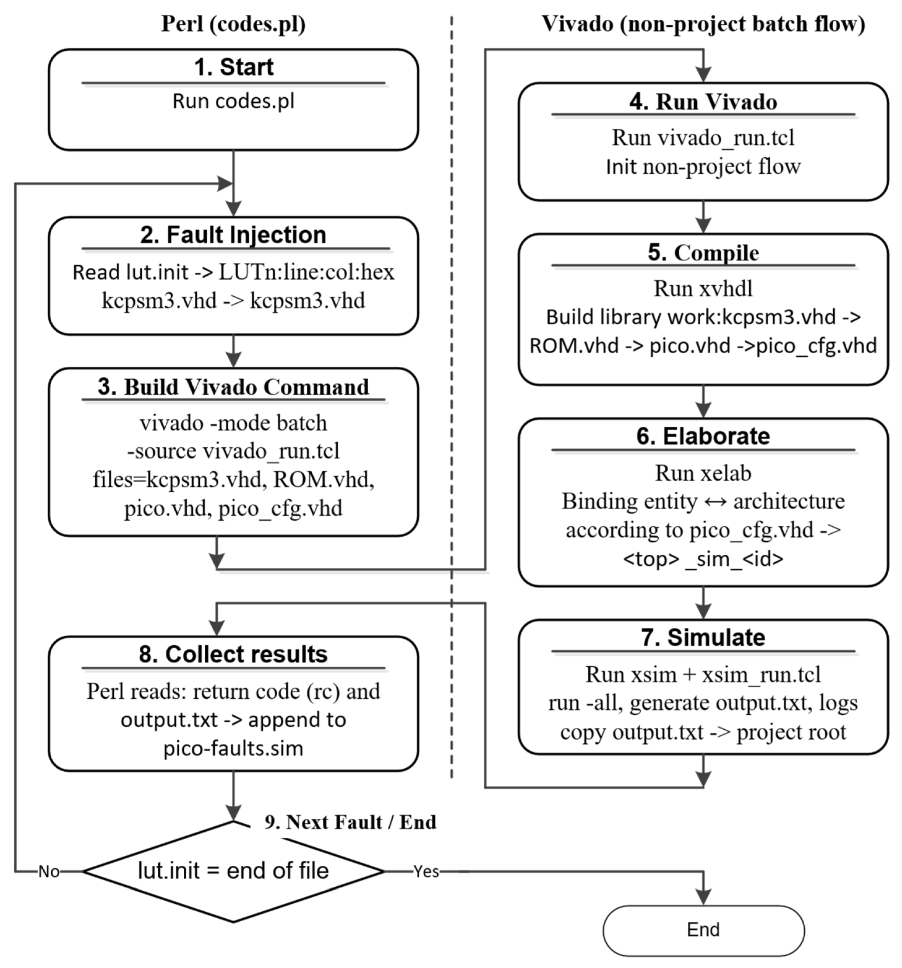
  • The CADENCE simulator generates a file of 256 output results for each fault injected in PicoBlaze. For any 8-bit processor, the number of different generated results is 256, each for a different input test vector. Then, these results are compared to the results contained in the reference file. The entire operation is repeated 1804 times for each injected fault one by one. This generates 461,824 (256 × 1804) results. Finally, the pico-fault.sim result file was compared with the reference file results.txt, which contains 256 correct results. If any result inside the frame of 256 results is wrong, the fault is detected. It should be emphasized that this version of the script modifies the LUT functions by introducing a single bit-flip. According to this rule, 1108 faults can be injected into the description of PicoBlaze. The remaining 883 faults were of the stuck-at type. This resulted in a total of 1804 faults. This is the exhaustive set of single bit-flip faults for PicoBlaze. If necessary, the script can also inject multi-bit flip faults. The above-described Perl script flowchart is shown in Figure 7.
In some cases, it may happen that a single bit flip in the LUT content will also cause a stuck-at fault at the LUT inputs or outputs. In this case, the script skips generating the same fault multiple times. When stuck-at faults are modelled, more bits in the LUT can be changed simultaneously.
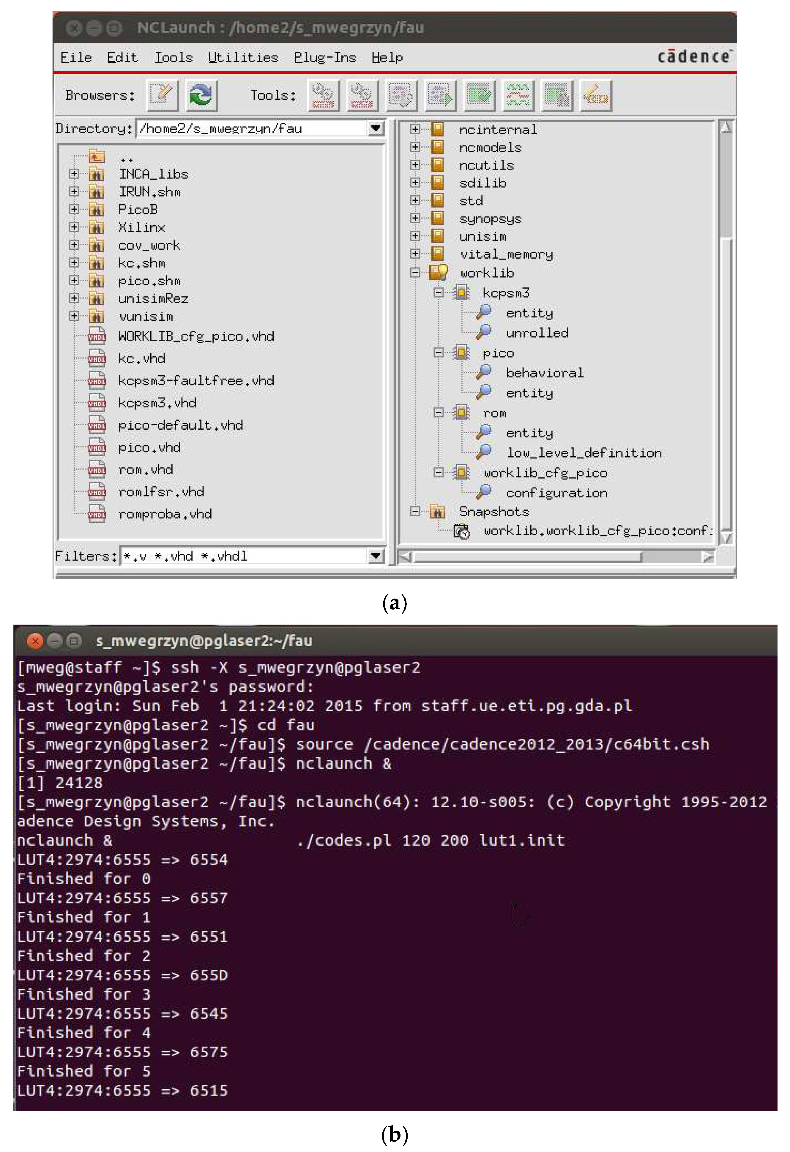
An example of the Cadence tool window and the execution progress of the simulation with injected faults driven by the Perl script, as observed in the Ubuntu terminal, is presented in Figure 8.

4.2. PicoBlaze Microcontroller Case Study

The PicoBlaze microcontroller is dedicated to the Xilinx Spartan FPGA families [44]. It is an 8-bit microcontroller with sixteen 8-bit registers; 1K of program memory; 64-byte scratchpad RAM; a 31-location stack; and 256 input and 256 output ports. Its structural VHDL description is divided into 14 blocks. The list of all its functional blocks is presented in Table 1, together with occupied FPGA resources. The script injected 1804 single-bit faults into all 109 LUTs, functionally constituting PicoBlaze. We chose PicoBlaze for experiments because all details of its structural VHD description are essentially the same as those of larger microcontrollers such as SecretBlaze, RISC-V, etc. The VHD structural description of a given device depends on the selected FPGA model. For example, if we select a Xilinx 7-series device, the generated VHDL structural description will be based on six-input LUTs. A structural HDL description of any system described at the behavioral level can be easily obtained by running the implementation tool in Xilinx Vivado. For larger systems, the experimental time will predictably increase proportionally. For test programs as well-developed as ours for PicoBlaze, we expect similar fault coverage. We concluded that it is a good idea to test our fault injection tool on various logic circuits, such as decoders, logic circuits, arithmetic circuits, and memories. The PicoBlaze architecture contains ten such blocks. We deliberately chose not to use very complex circuits to avoid unnecessarily prolonging the test and development time of our FI tool. We argue that the tool will operate with the same precision regardless of the size of the selected application. Additionally, the repeatability of fault injection effects in FPGAs is very high, which undermines the testing of our tool on a large number of identical LUTs.
The execution time of the test program proposed in [8] does not exceed 3.5 h on a PC with an Intel 24-core i9. The SEU simulation time for a single fault is approximately 7 s. During this time, the test program is executed 256 times, and it generates 256 numerical results. This time depends significantly on PC performance and simulator software (CADENCE), as well as on factors such as the length of the PicoBlaze test program and the processor clock speed. Moreover, the designer does not have to inject faults into the entire VHDL model every time. In the fault source’s file “lut.init”, it is easy to set the range of lines of a VHDL model (a specific hardware block) that is currently under development. This gives the designer of SEU-resistant systems the opportunity to speed up the evaluation time.

4.3. Fault Coverage Results

The behavior of the PicoBlaze core after the injection of each fault was tested primarily using the original assembler test program developed by the authors of [8] and also using other computational applications, such as matrix multiplication algorithms (MM1, MM2, and MM3) and Fibonacci number generators, for comparative purposes.
Fault coverage (FC) is defined as the percentage of detected faults over all injected faults:
FC = (no. Faults detected/no. Faults injected) × 100 [%]
The most important fault coverage results are presented in Table 2. The best result was achieved by the test program with full bijective property, with a linear feedback shift register (LFSR) solution applied to SHIFT block testing [8]. The middle column shows the FC of stuck-at faults, while the right column shows the total coverage of all injected faults (stuck-at + functional SEU-induced).
Table 3 collects information about the number of undetected faults in individual PicoBlaze blocks. Also, the ratio of undetected faults in each specific block (right column) is obtained. This information was used for researching improvements for the test program and analyzing the mechanisms of the so-called logical redundancies occurring during fault injection in LUTs. This table also shows the amount of FPGA resources occupied by each processor block and the number of injected faults in the specific block. Most undetected faults occur in the blocks that work with peripherals, which were not tested here (read/write strobes and interrupt input circuits).

4.4. Integrating the Perl Script into the Xilinx Vivado Environment

The developed software tool can interact with EDA systems from different vendors. We used TCL (tool command language) scripts, which are supported by most design environments, including Vivado. The algorithm in Figure 9 shows how the developed tool operates with Vivado. The algorithm consists of nine stages, and they are as follows:
Stage 1 (Start)—Execution of the Perl Script Begins: This is a preparatory step where the system loads input data, defines environment parameters, and enters the main control loop.
Stage 2 (Fault Injection)—The Core Stage of Mutation Creation Within the Processor: The program reads the lut.init file containing the LUT number and the INIT value with an injected fault (in the format LUTn:line:col:hex), and it replaces the corresponding INIT value in the kcpsm3-faultfree.vhd file. A new file, kcpsm3.vhd, is generated, which contains one faulty LUT configuration. Additional files required for the SEU simulation are also prepared.
Stage 3 (Build Vivado Command)—The Program Constructs a Console Command to Launch Vivado: It specifies the TCL script vivado_run.tcl, which implements the stages of compilation, elaboration, and simulation, and it passes the following parameters to it: files=kcpsm3.vhd, ROM.vhd, pico.vhd, pico_cfg.vhd, top=pico_cfg, and id=NNNN. This enables non-project compilation, elaboration, and simulation. This stage serves as the link between the external Perl automation and Vivado, providing complete integration without creating a GUI project.
Stage 4 (Run Vivado)—Control is Transferred from Perl to Vivado: The file vivado_run.tcl is executed, initiating the non-project flow, creating the working directory _xsim_<id>/, setting paths to xvhdl/xelab/xsim, and opening the log file xsim_<id>.log for subsequent sub-stages.
Stage 5 (Compile—xvhdl): Vivado compiles the VHDL modules (kcpsm3.vhd, ROM.vhd, pico.vhd, and pico_cfg.vhd) and builds the working library for further Elaboration (xelab) and simulation (xsim). It checks syntax, port compatibility, and architecture consistency. This stage is the connecting link between textual VHDL files and the SEU simulation environment, ensuring structural integrity of the project and preparing a verified design representation for the simulator.
Stage 6 (Elaborate—xelab): Vivado forms a linked simulation model, binding entity↔architecture according to pico_cfg.vhd. This stage acts as an intermediate link between compilation (xvhdl) and simulation (xsim), because, here, the individual structural units of the design are combined into a coherent model that the simulator executes.
Stage 7 (Simulate—xsim): Vivado/XSIM performs the execution of the elaborated simulation session, managed automatically through the auxiliary TCL script xsim_run.tcl. This script runs the testbench, collects output data, and transfers the results back to the Perl program. After completion, XSIM generates a log and result file called output.txt, which will later be analyzed by the Perl script.
Stage 8 (Collect Results)—Control Returns to Perl: The script checks the process return code, reads or copies output.txt, and appends the result to pico-fault.sim. If an error occurs, the run status is logged, and the program proceeds to the next record in lut.init. This stage completes one full fault-injection simulation cycle before passing to the next case.
Stage 9 (Next Fault/End): This stage finalizes one iteration of defect processing and manages the transition to the next record in lut.init, enabling the sequential execution of all planned fault injections. The Perl script checks whether another entry exists in lut.init. If so, the cycle repeats stages 2–8. If all entries were processed, the script generates a final report in pico-fault.sim and terminates the operation of the automated fault-simulation system, producing a complete set of experimental results.
As a result of our new experiment in the Vivado environment, we achieved exactly the same FC as for the CADENCE-based experiment. However, the experiment time was significantly shorter, around 4.5 s for a single SEU fault simulation, due to Vivado’s lower workstation requirements than those of CADENCE VHDL.

5. Investigation of the Fault-Masking Mechanism

The fault-masking phenomena occur when the appearance of an SEU fault in a circuit does not result in a functional fault at the circuit output(s). These phenomena are classified as logical or electrical [30]. In this paper, we focus on masking the logical fault related to FPGAs. Masking of the SEU-induced faults can be called SEU filtering. The occurrence of these phenomena depends on the architecture of the digital circuit. For example, if “0” is present on one input of an “AND” gate, the faulty value “1” on the other input of this gate is not propagated to the gate output [4]. If an SEU induces a fault in an FPGA, the situation can be similar but more complex. In FPGAs, additional circuits can be generated and connected to the desired circuit in various ways as a result of a fault injected into the LUT. Conversely, certain circuits can be reduced. Sometimes it turns out that these modifications do not affect the functionality of the system and therefore do not cause any changes in its outputs. By the same principle as shown in Section 3, SEUs can generate additional components (terms) of logical functions or reduce these terms. Based on the theory of combinational circuits [30], the following can be distinguished: redundant terms, redundant variables of terms, reduced logical terms, reduced variables of terms, and changed variables of terms.
Using various versions of dedicated test programs and computational applications for PicoBlaze, we demonstrated that many faults remained undetected. Table 2 provides us with the information that the total number of faults not detected by any of the test programs is 84 out of all 1804 injected. Therefore, fault coverage (FC) of less than 100% was achieved.
Analyzing fault detection mechanisms is not only time-consuming but also very revealing. It involves observing the interactions between hardware and the relevant data. We investigated a number of faults not detected by any of the programs. These investigations revealed the reasons why some number of faults remain undetected. This was caused by modified logical functions that produce the same logical values as the intended ones. These phenomena can be called logical redundancies.
Injecting a single fault results in modifying the logical function generated by the LUT in several different ways. Namely, the generated objects can be as follows:
  • Redundant term(s) (of logic sum): Its logical value is equal to “0” for all possible input data. Therefore, such an additional component of logical sum is not capable of causing any detectable difference in results;
  • Redundant variables of terms;
  • Reduced term(s);
  • Reduced variables constituting the logic terms. Also, reduced terms and variables in logical sums cannot, in every case, change the final logical values of the logical expression;
  • Changed one or more variables constituting the terms (of a logic sum).
The distribution of logical redundancies of the classified types in the specific microcontroller blocks is summarized in Table 4. Next, several analyses of the logical redundancy examples specified in Table 4 are presented in detail. These examples are intended to explain the various mechanisms of fault masking.

5.1. The Case of the Redundant Term Located in Logical Operations—Block (No. 5)

The injected fault number 1054, described as X”6E8A” => X”6E8B”, remained undetected. The logical_value signal is used to generate the logical_result signal. The correct VHDL code of this block is shown in Figure 10a., while the modified vhdl description with the changed “INIT” parameter is presented in Figure 10b.
The following logical expressions were derived in cases of original and faulty “INIT” parameters applying the Karnaugh map method. The logical function generated by the original VHDL code is as follows:
O = (I0 (!I1) I3) + (I0 (!I2) + (I0 I1 (!I3)) + ((!I0) I1 I3)),
Moreover, the function after modifying the parameter is as follows:
O = (I0 (!I2)) + (I0 I1 (!I3)) + ((!I1) (!I2) (!I3)) + ((!I0) I1 I3) + (I0 (!I1) I3)).
The above modification of parameters results in a “redundant term”: ((!I1) (!I2) (!I3)). To detect this fault, the seventh bit in the register sx should have a value of “0”, and the 13th and 14th bits in a logical instruction should have a value of “0”. These conditions are met merely by the execution of the logical instruction “LOAD”. Thus, this fault is detectable if specific conditions are met. However, this fault can be easily masked, because it is sufficient that the seventh bit in register sx contains a non-zero value generated by the previous instruction.

5.2. The Case of the Redundant Variables of the Logical Term Located in the Block of Arithmetic Operations—(No. 7)

Fault number 1257, described as X”1F” => X”1D”, remains undetected. This LUT plays the role of the decoder of arithmetical operations. The correct logical value is generated as “0”. The correct and faulty VHDL code of this block is shown in Figure 11a and Figure 11b, respectively.
The logical expression of the original function generated by the LUT is as follows:
O = (!I2) + ((!I0) (!I1)).
In contrast, the wrong LUT parameter implements the following modified logic function:
O = ((I1) (!I2)) + ((!I0) (!I1)).
It is clear that the first term of the logic sum depends additionally on the redundant I1. The 15th bit of the assembler instruction is sent to the LUT input I1 (see PicoBlaze VHDL). Based on the table of “PicoBlaze instructions codes”, it can be deduced that this fault does not disturb the flow of outgoing data calculated by arithmetic instructions. All arithmetic instructions have the 16th bit of the assembler instruction set to “1”. Therefore, the additional variable I1 of the first term of the logical sum (!I2) I1, generated by the wrong parameter “INIT”, is independent of the I1 to 15th bits, and it is still equal to “0”. In this way, this fault has no effect on the flow of results generated by arithmetical instructions. Thus, this fault remains undetectable by any assembler programs. This fault can be tolerated by the processor core. This was an example of the fault classified as “Redundant variables of terms”.

5.3. The Example of the Reduced Term in SHIFT and ROTATE Operations—Block (No. 6)

A more complex fault-masking mechanism was discovered in the SHIFT block. The LUT generating the shift multiplexer function shift_mux_LUT0 is depicted in Figure 12.
The logical expression generated by the correct LUT function is as follows:
O = (!I0 I1) + (I0 I2)
In contrast, the wrong LUT parameter implements the following modified logic function:
O = I0 I2, where logical term (!I0 I1) was removed.
Based on the PicoBlaze User Guide, it can be proven that right shifts generate the correct results if they have the third bit of the instruction set to “0”. The execution of right shifts will mask this fault. Only left shifts with the third bit of the instruction set to “0” and the value of the signal shift_in set to “0” will detect this fault. The shift_in signal is generated by the preceding LUT.
Therefore, after these analyses, it can be concluded that fault detection inside the “SHIFT” block is multi-stage. This is because the data are transferred through more blocks for which their logic is implemented by a larger quantity of LUTs. A successful fault detection requires not only careful design of the test program but also a precise and often complex selection of test vectors.

5.4. The Case of the Reduced Variables of ONE Term in ZERO and CARRY Flags—Block No. 3

Fault number 154 X”41FC” =>X”41FD” injected in this block remained undetected. This fault may affect the flag_enable signal. This signal enables the correct propagation of the proper CARRY_FLAG through the Xilinx FDRE flip-flop. When the flag_enable signal on the clock enable (CE) input obtains a value of “1”, the FDRE flip-flop is activated, and the CARRY_FLAG is propagated. The correct and faulty VHDL code of this block is shown in Figure 13a and Figure 13b, respectively.
The original logical equation generated by the LUT is as follows:
O = ((!I0) I1 I2) + (I1 (!I3)) + (I2 (!I3)) + ((!I0) (!I1) (!I2) I3)
In contrast, the wrong LUT parameter implements the modified logic function with reduced variable I3:
O = ((!I0) I1 I2) + (I1 (!I3)) + (I2 (!I3)) + ((!I0) (!I1) (!I2)).
After modifying the INIT parameter, the variable I3 was reduced from the logical term.
Based on the PicoBlaze User Gude, it is possible to infer that the term ((!I0) (!I1) (!I2) I3) does not have I3 concerns (the 17th bit) with respect to the “LOAD” assembler instruction, and it can be set to “1” with respect to the flag_type signal; also, flag_enable signals are present during the execution of “LOAD”.
It can be further concluded that this fault is undetectable because the “LOAD” instruction does not set any flags; therefore, the activation of flag-setting signals during the execution of this instruction will be invisible and will not affect the results of program execution in any way. Furthermore, it is not possible to write any test program that would be able to detect this fault.
The important observation is that the flag-generating instructions, for which their 17th bit is set to “1” by default, also include SHIFT and ROTATE instructions. However, it can be noticed that these instructions do not need the 17th bit of the assembly instruction to generate flags correctly.

5.5. Example of Changes in Variables of the Logical Term in ZERO and CARRY Flags—Block No. 3

The “TEST” assembler instruction is computed by the LUT, which generates the flag_type signal to form odd parity information, and finally, the instruction sets parity or the odd flag.
There are many undetected faults (14) remaining in this block. The reason for this is that the logical value of the function computed by the LUT remains unchanged when the INIT parameter value is changed, even though the LUT then generates a different logical equation.
According to Figure 14, the original logical function generated by LUT: INIT => X”F3FF” is as follows:
O = !I1 + I2 + !I3,
and the modification of the INIT parameter causes it to change as follows:
O = (!I1 !I3) + I2 + (I1 I3) + (I0 !I3).
In this way, the “Variables of logic terms” were changed. After substituting the corresponding bits of the assembler instruction for I1, I2, and I3 and fusing the “TEST” instruction format, it turns out that the logical value of the new expression is “0”. This is exactly the same as the original one (the I1 = 13th bit of the “TEST” instruction always obtains a value of “1”; the I2 = 15th bit of the instruction obtains a value of “0”; the I3 = 16th bit of the instruction obtains a value of “1”). The situation has not changed despite the modification of the parameter INIT: F3FF => F3FE. The results generated by the LUT function, after parameter INIT => X”F3FD”’s modification, take the following form:
O = (I1 !I3) + I2 + (!I1 I3) + (!I0 !I3).
Other examples include the following:
INIT => X”F3FB”: O = (I0 !I3) + I2 + !I1,
INIT => X”F3FB”: O = (I0 !I3) + I2 + !I1
INIT => X”EF”: O = (I0 !I3) + (I1 + !I3) + (!I1 I3) + (I2 I3) + (!I2 !I3).
The situation is the same for the other nine parameter changes.
To conclude this section, it should be noted that if some faults do not affect the operation of the processor implemented on the FPGA due to redundancy, this is ultimately a positive effect—the processor implemented on the FPGA is resistant to these faults. However, in the case of problems with fault coverage calculations, a redundancy library can be created, and during testing, a given error can be automatically classified as redundant in a given class from the Table. In this way, it is possible to speed up the fault coverage’s calculation. We would like to draw special attention to the fact that this type of phenomenon does not occur in the case of the classical modeling of stuck-at faults in the FPGA through hardware modifications. During our research, we also encountered another problem: Namely, a logical function designed as a composition of several functions generated by different LUTs may remain unchanged despite changing the INIT parameter value of one LUT component. The relevant example was described in detail in the case of LOAD and TEST instructions (Section 5.3).

6. Discussion

The main drawback of our tool is the relatively long simulation time. It takes approximately 7 s for a single fault. Another disadvantage is the inability to introduce faults into the configuration of routing resources, such as interconnection switches. However, faults between slices inside configurable logic blocks (CLBs) are modelled as stuck-at LUT inputs. In turn, faults between the LUT outputs and the flip-flops and multiplexers inside the slices are modelled as stack-at LUT outputs.
In order to compare the results of our solution with those presented in the bibliography, we can convert the fault sensitivity metrics proposed by other authors into fault coverage (FC). For example, the authors of [14] defined the architectural vulnerability factor (AVF) as the percentage of damage inflicted over the total number of injections. The numerical value of AVF is the same as the FC defined by us, i.e., the percentage of faults detected by the test program over the total number of injected faults.
The emulation-based solutions presented in Table 5, despite injecting a large number of faults into the user application bitstream, achieved a maximum of 72% FC. Considering the reliability of the application, this is a rather good result. On the other hand, with respect to the predictability of the presented tools in the bibliography and the difficulties of precisely controlling them, the locations of injected faults can be discussed, as approximately 28% or more of the injected faults were not detected by the application. It can be calculated that for the fault coverage achieved, proportionally 7.27 times fewer injected faults were sufficient than those used in [18] due to the fact that PicoBlaze occupies 26 slices in the Xilinx 7-series FPGA, whereas the FFT tested in [10] occupies 1079 slices, which is 41.5 time more: 544,123 (total injected fault FFT)/41.5 = 13,111.4, 13,111.4/1804 = 7.27. The fault coverage results achieved in other publications are summarized in Table 5.
The main reason for these significant differences in fault coverage between the tested systems is the fact that tools that inject faults randomly, e.g., by manipulating the bitstream [1,18,26] typically inject a large percentage of faults into the part of the FPGA not occupied by the application under test, or they carry out injections into memory locations where data are not currently used by the application. Deterministic FI methods [4,14] achieved higher FC than pseudo-random ones. Positions 1 and 2 in Table 5 are occupied by SEU simulation-based fault injection methods. Munoz [14] obtained the highest fault coverage for a simple counter circuit. Our method is a deterministic SEU simulation method, where we tested the PicoBlaze processor core consisting of 10 blocks representing control logic, arithmetic logic, logical logic, decoders, memory modules, etc. There were numerous complex problems related not only to logical fault masking but also to hardware redundancies described in our earlier publications [8]. The authors of [16] introduced dynamic partial reconfiguration. Hence, one can say that the modified bit stream is responsible for specific frames describing the circuits occupying the FPGA resources. Therefore, the precision of fault injection is much higher here than in the case of purely random FI. However, using our method, it is much easier to inject faults than in the case of this method. In addition, our script achieved 100% precision. The effectiveness of the developed tests is also important. They may achieve less than 100% of detected faults, even if a given FI tool injected an exhaustive set of faults into the FPGA resources occupied by a given application.
It is worth noting that none of the authors achieved 100% FC for any of the tested systems. It can be assumed that the reason for this may be logical redundancies and other issues related to both specific projects and the tool.
The advantage of our new tool is that it can deterministically inject SEU faults into precisely defined locations in an FPGA. The faults injected by this tool produce the same effects as the physical phenomena of SEUs. Due to precise fault modelling at the level of structural HDL codes, a high fault coverage of 94.75% was achieved in the PicoBlaze test. We expect similar FC for test programs as well developed as ours for PicoBlaze. Moreover, applying emulation methods and analyzing how a single fault results in hardware modification is more difficult than in our solution (see Section 3). It can be predicted that fault injection in the LUTs of different FPGA families will also result in logical redundancies. We can expect more complex redundant logical expressions for six-argument functions generated by LUT6 than for functions generated by LUT4. Finally, the quantity of logical redundancies depends on the DUT. The appearance of logical redundancies makes the process of calculating fault coverage more difficult. To mitigate the impact of these effects, we propose creating a redundancy library for a given FPGA family. Another advantage of our new tool is its flexibility, as after making minor modifications, it can also inject faults into Verilog descriptions, and it can work with other known FPGA simulation tools built in the Xlinx Vivado, ISE, or Altera Quarus Prime environments, not only with the CADENCE VHDL simulator. This tool can be used to examine any LUT-based FPGA technology regardless of the age of its implementation.

7. Conclusions

The main contribution of this paper is a new universal and precise tool for injecting faults into a VHDL or Verilog structural description. This tool was primarily designed to work with the professional CADENCE VHDL simulator. Furthermore, it is also compatible with other simulators built in Xilinx Vivado (or Isim) or Altera Quartus Prime after minor modifications. Our contribution is complemented by the recently implemented version of our tool that works with the Xilinx Vivado environment. It is currently being tested and refined. Our tool injects both functional permanent faults in LUTs and stuck-at faults at LUT inputs and outputs. In this way, we can model some parts of the connection faults. However, the main drawback of our tool is the inability to inject faults into switches in the global FPGA interconnection network. On the other hand, focusing on precise fault injection in LUTs brought significant benefits, such as the ability to achieve high fault coverage, 100% repeatability of FI experiments, faithful replication of SEUs, and easy predictability of circuit modifications generated by a specific fault injected in the LUT. This predictability is much weaker in the case of emulation methods that involve the modification of the configuration’s RAM. Consequently, the fault coverage achieved by these methods is significantly lower. The new tool allows for the easy modification of the fault injection scope in selected hardware blocks of a design or its subcircuits. This considerably reduces the time of experiments. This tool can also be used to evaluate the reliability and radiation immunity of any designs implemented on FPGAs, not only processor cores.
Our research proved that achieving 100% FC is impossible by any test program written in the assembler for the reason of logical redundancies in the case of a fault injected in LUTs implementing a microcontroller on FPGAs. The results presented in Section 5 revealed that 84 (4.65%) of the injected faults (1804) were not detected due to the discovered logical redundancies. We classified the types of possible logical redundancies. Based on this classification, we plan to create a redundancy library. This library will be useful in future work to further automate tools and speed up the calculation of FC.
We recommend using our new FI tool with various VHDL/Verilog simulators to evaluate both the quality of test programs for miscellaneous processor cores implemented on an FPGA and the resilience of applications exposed to external factors. We offer the readers a license-free FI tool (accessed on 10 November 2025): https://drive.google.com/file/d/13xc1bH3yJ-agiYQ8Mh1WVz5NjBCskOsQ/view?usp=sharing.
Therefore, future work may involve running this tool on other VHDL/Verilog simulators, as well as minor modifications to enable fault injections into the VHDL/Verilog description of other FPGA families that are based on other LUTs with more than four inputs. We decided to refine our fault injection environment, relying on Xilinx Vivado tools. Our latest experiments showed that they do not require powerful workstations such as CADENCE VHDL to generate results faster. A single SEU simulation takes 4.5 s instead of 7 s, as in the case of CADENCE, using the same workstation with an Intel Core i9 processor and 32 GB of RAM. The next tests will concern integration with the Questa/Intel Altera simulator, which is designed to work with the Quartus Prime software 24.1.
Going forwards, we will plan to test the reliability of the applications, and we will research new numerical methods for floating-point calculations implemented directly on FPGA logic. Furthermore, we intend to investigate the reliability of these numerical methods implemented as C functions and executed on an RISC-V processor over a slightly prolonged period. Our numerical algorithms are characterized by higher accuracy compared to those offered by conventional C/CPP functions from libraries [45]. Their FPGA implementations may be applied to research in physics and chemistry, along with other fields. These algorithms, implemented directly in FPGA logic or executed on microprocessors as C functions, can be integrated into research platforms operating, among others, in space or in environments used for conducting physical research, such as particle accelerators at the European Council for Nuclear Research (CERN), etc.
Additionally, we provide an alternative utilization of our new tool through special implementations of DSP blocks based on digital filters dedicated to telecommunication systems, which is currently under study by our team.

Author Contributions

Conceptualization: M.W.; methodology: M.W.; software: M.W. and I.M.; validation: M.W., I.M. and O.K.; formal analysis: M.W.; investigation: M.W.; resources: M.W.; data curation: M.W.; writing—original draft preparation: M.W. and I.M.; writing—review and editing: O.K.; visualization: M.W.; supervision: M.W.; project administration: M.W.; funding acquisition: M.W. All authors have read and agreed to the published version of the manuscript.

Funding

This research received no external funding.

Data Availability Statement

We only provide readers with our Perl script, which is the core of our solution. Readers can modify it and use it freely to test their own applications. We do not disclose the entire research project because we intend to conduct further research and publish new results.

Acknowledgments

We would like to express our gratitude to Marta Wagner for her invaluable help in editing the English of this article while taking technical vocabulary into account. Marta Wagner received a Certificate of Translation of Texts in Technology and Law, no. 56/b/15 in 2016, from The Translation Studies, Sosnowiec, Poland.

Conflicts of Interest

The authors declare no conflicts of interest.

References

  1. Zhang, R.; Xiao, L.; Li, J.; Cao, X.; Qi, C. A Fault Injection Platform Supporting Both SEU and Multiple SEUs for SRAM-Based FPGA. IEEE Trans. Device Mater. Reliab. 2018, 18, 599–605. [Google Scholar] [CrossRef]
  2. Gao, Z.; Feng, J.; Gao, S.; Liu, Q.; Ge, G.; Wang, Y.; Reviriego, P. Modeling the Effect of SEUs on the Configuration Memory of SRAM-FPGA-Based CNN Accelerators. IEEE J. Emerg. Sel. Top. Circuits Syst. 2024, 14, 799–810. [Google Scholar] [CrossRef]
  3. He, W.; Li, J.; Zhou, Y.; Lin, J. Study on an Estimation Method of On-orbit Single Event Upset Rate Based on Historical Data. In Proceedings of the 2021 IEEE 4th International Conference on Electronics Technology (ICET), Chengdu, China, 7–10 May 2021; pp. 1342–1346. [Google Scholar] [CrossRef]
  4. Węgrzyn, M.; Jamro, E.; Dąbrowska-Boruch, A.; Wiatr, K. Optimal Reduction in the Number of Test Vectors for Soft Processor Cores Implemented in FPGA. Electronics 2021, 10, 2505. [Google Scholar] [CrossRef]
  5. Masar, F.; Mrazek, V.; Sekanina, L. Late Breaking Result: FPGA-Based Emulation and Fault Injection for CNN Inference Accelerators. In Proceedings of the 2025 Design, Automation & Test in Europe Conference (DATE), Lyon, France, 31 March–2 April 2025; pp. 1–2. [Google Scholar] [CrossRef]
  6. Wang, W.; Li, X.; Chen, L.; Sun, H.; Zhang, F. A Review on Soft Error Correcting Techniques of Aerospace-Grade Static RAM-Based Field-Programmable Gate Arrays. Sensors 2024, 24, 5356. [Google Scholar] [CrossRef]
  7. Malagón, D.; Torrens, G.; Segura, J.; Bota, S.A. Single Event Upsets characterization of 65 nm CMOS 6T and 8T SRAM cells for ground level environment. Microelectron. Reliab. 2020, 110, 113696. [Google Scholar] [CrossRef]
  8. Węgrzyn, M.; Sosnowski, J. Tracing fault effects in FPGA systems. Int. J. Electron. Telecommun. 2014, 60, 103–108. [Google Scholar] [CrossRef]
  9. Ruano, Ó.; García-Herrero, F.; Aranda, L.A.; Sánchez-Macián, A.; Rodriguez, L.; Maestro, J.A. Fault Injection Emulation for Systems in FPGAs: Tools, Techniques and Methodology, a Tutorial. Sensors 2021, 21, 1392. [Google Scholar] [CrossRef] [PubMed]
  10. Paiva, D.; Duarte, J.M.; Lima, R.; Carvalho, M.; Mattiello-Francisco, F.; Madeira, H. Fault injection platform for affordable verification and validation of CubeSats software. In Proceedings of the 2021 10th Latin-American Symposium on Dependable Computing (LADC), Florianópolis, Brazil, 22–26 November 2021; pp. 1–11. [Google Scholar] [CrossRef]
  11. Pitchaimani, B.; Sridharan, M. A novel emulation method to assess the effects of cosmic radiation for avionics SoC using the GA based fault injection hardware. Sadhana 2022, 47, 61. [Google Scholar] [CrossRef]
  12. Eslami, M.; Ghavami, B.; Raji, M.; Mahani, A. A survey on fault injection methods of digital integrated circuits. Integration 2020, 71, 154–163. [Google Scholar] [CrossRef]
  13. de Oliveira, A.B.; Tambara, L.A.; Benevenuti, F.; Benites, L.A.C.; Added, N.; Aguiar, V.A.P.; Medina, N.H.; Silveira, M.A.G.; Kastensmidt, F.L. Evaluating Soft Core RISC-V Processor in SRAM-Based FPGA Under Radiation Effects. IEEE Trans. Nucl. Sci. 2020, 67, 1503–1510. [Google Scholar] [CrossRef]
  14. Muñoz-Quijada, M.; Sanz, L.; Guzman-Miranda, H. A Virtual Device for Simulation-Based Fault Injection. Electronics 2020, 9, 1989. [Google Scholar] [CrossRef]
  15. Monopoli, M.; Biondi, M.; Nannipieri, P.; Moranti, S.; Fanucci, L. RADSAFiE: A Netlist-Level Fault Injection User Interface Application for FPGA-Based Digital Systems. IEEE Access 2025, 13, 28809–28823. [Google Scholar] [CrossRef]
  16. Ferlini, F.; Viel, F.; Seman, L.O.; Pettenghi, H.; Bezerra, E.A.; Leithardt, V.R.Q. A Methodology for Accelerating FPGA Fault Injection Campaign Using ICAP. Electronics 2023, 12, 807. [Google Scholar] [CrossRef]
  17. Pensec, W.; Lapôtre, V.; Gogniat, G. Scripting the Unpredictable: Automate Fault Injection in RTL Simulation for Vulnerability Assessment. In Proceedings of the 2024 27th Euromicro Conference on Digital System Design (DSD), Paris, France, 28–30 August 2024; pp. 369–376. [Google Scholar] [CrossRef]
  18. Feng, H.; Li, W.; Chen, L.; Wang, S.; Zhou, J.; Tian, C.; Zhang, Y. Precise Fault Injection and Fault Location System for SRAM-based FPGAs. In Proceedings of the 2022 IEEE 10th Joint International Information Technology and Artificial Intelligence Conference (ITAIC), Chongqing, China, 17–19 June 2022; pp. 2371–2376. [Google Scholar] [CrossRef]
  19. Liu, Y.; Yao, L.; Zhang, W.; Wang, Y.; Jiang, X.; Li, F.; Xu, Q. SEU Fault Injection Strategy for SRAM-based FPGA User Memory Based on Dual-Circuit Model. J. Electron. Test. 2025, 41, 75–84. [Google Scholar] [CrossRef]
  20. Vacca, E.; Buccellato, F. POSTER: Hardware-Aware Software-Based Fault Injection Platform for DNN Accelerators. In Proceedings of the 22nd ACM International Conference on Computing Frontiers (CF’25), Cagliari, Italy, 28–30 May 2025; Cagliari Association for Computing Machinery: New York, NY, USA, 2025; pp. 220–221. [Google Scholar] [CrossRef]
  21. Alhayan, F.; Kaur, G.; Alanazi, S.; Rehman, M.B.; Mansouri, W.; Albalawneh, D.; Alqazzaz, A.; Alkhudhayr, H. DA-FIS: A high-speed dynamic adaptive fault injection server framework for reliable FPGA-based embedded systems. PeerJ Comput. Sci. 2025, 11, e2996. [Google Scholar] [CrossRef] [PubMed] [PubMed Central]
  22. Siecha, R.T.; Alemu, G.; Prinzie, J.; Leroux, P. Analysis of the SEU Tolerance of an FPGA-Based Time-to-Digital Converter Using Emulation-Based Fault Injection. Electronics 2025, 14, 2176. [Google Scholar] [CrossRef]
  23. Tuzov, I.; de Andrés, D.; Ruiz, J.-C.; Hernández, C. BAFFI: A bit-accurate fault injector for improved dependability assessment of FPGA prototypes. In Proceedings of the 2023 Design, Automation & Test in Europe Conference & Exhibition (DATE), Antwerp, Belgium, 17–19 April 2023; pp. 1–6. [Google Scholar] [CrossRef]
  24. Brömer, F.; Kenny, P.; Lund, A.; Gremzow, C.; Lüdtke, D. FPGA-Based Fault Injector for SEU-Robustness Analysis of ScOSA; Deutsche Gesellschaft für Luft- und Raumfahrt—Lilienthal-Oberth e.V.: Bonn, Germany, 2023. [Google Scholar] [CrossRef]
  25. Alderighi, M.; Casini, F.; D’Angelo, S.; Mancini, M.; Codinachs, D.M.; Pastore, S.; Poivey, C.; Sechi, G.R.; Weigand, G.S.R. Experimental validation of fault injection analyses by the FLIPPER tool. In Proceedings of the 2009 European Conference on Radiation and Its Effects on Components and Systems, Brugge, Belgium, 14–18 September 2009; Volume 57, pp. 544–548. [Google Scholar] [CrossRef]
  26. Zhang, Y.; Chen, L.; Wang, S.; Zhou, J.; Tian, C.; Feng, H. Research on agile FPGA fault injection system. In Proceedings of the 2021 International Conference on Microelectronics (ICM), New Cairo City, Egypt, 19–22 December 2021; pp. 57–61. [Google Scholar] [CrossRef]
  27. Aponte-Moreno, A.; Isaza-González, J.; Serrano-Cases, A.; Martínez-Álvarez, A.; Cuenca-Asensi, S.; Restrepo-Calle, F. Evaluation of fault injection tools for reliability estimation of microprocessor-based embedded systems. Microprocess. Microsyst. 2022, 96, 104723. [Google Scholar] [CrossRef]
  28. Muñoz-Quijada, M.; Sanchez-Barea, S.; Vela-Calderon, D.; Guzman-Miranda, H. Fine-grain circuit hardening through VHDL datatype substitution. Electronics 2018, 8, 24. [Google Scholar] [CrossRef]
  29. Altera Corporation. SEU Mitigation User Guide; Intel Altera: Santa Clara, CA, USA, 2024. [Google Scholar]
  30. European Space Agency. Space Engineering. In Engineering Techniques for Radiation Effects Mitigation in ASICs and FPGAs Handbook; European Space Agency: Paris, France, 2023. [Google Scholar]
  31. Dutton, B.; Ali, M.; Sunwoo, J.; Stroud, C. Embedded Processor Based Fault Injection and SEU Emulation for FPGAs. In Proceedings of the International Conference on Embedded Systems and Applications, Las Vegas, NV, USA, 14 July 2009; pp. 183–189. [Google Scholar]
  32. Wilson, A.E.; Wirthlin, M. Fault Injection of TMR Open Source RISC-V Processors using Dynamic Partial Reconfiguration on SRAM-based FPGAs. In Proceedings of the 2021 IEEE Space Computing Conference (SCC), Laurel, MD, USA, 23–27 August 2021; pp. 1–8. [Google Scholar] [CrossRef]
  33. Sari, A.; Psarakis, M. A fault injection platform for the analysis of soft error effects in FPGA soft processors. In Proceedings of the 2016 IEEE 19th International Symposium on Design and Diagnostics of Electronic Circuits & Systems (DDECS), Kosice, Slovakia, 20–22 April 2016; pp. 1–6. [Google Scholar] [CrossRef]
  34. de Andres, D.; Ruiz, J.C.; Gil, D.; Gil, P. Fault emulation for dependability evaluation of vlsi systems. IEEE Trans. Very Large Scale Integr. (VLSI) Syst. 2008, 16, 422–431. [Google Scholar] [CrossRef]
  35. Choi, S.; Yoo, H. Fast Logic Function Extraction of LUT from Bitstream in Xilinx FPGA. Electronics 2020, 9, 1132. [Google Scholar] [CrossRef]
  36. Barbirotta, M.; Angioli, M.; Mastrandrea, A.; Menichelli, F.; Cheikh, A.; Olivieri, M. Special Session: SE-UVM, an Integrated Simulation Environment for Single Event Induced Failures Characterization and its Application to the CV32E40P Processor. In Proceedings of the 2024 IEEE International Symposium on Defect and Fault Tolerance in VLSI and Nanotechnology Systems (DFT), Didcot, UK, 8–10 October 2024; pp. 1–6. [Google Scholar] [CrossRef]
  37. Serrano, F.; Alaminos, V.; Clemente, J.; Mecha, H.; Liu, S. NESSY: Una Plataforma de Inyección de Errores para una FPGA Virtex-5. JCRA. 2012. Available online: https://jornadassarteco.org (accessed on 25 December 2022).
  38. Ramos, A.; Maestro, J.A.; Reviriego, P. Characterizing a RISC-V SRAM-based FPGA implementation against Single Event Upsets using fault injection. Microelectron. Reliab. 2017, 78, 205–211. [Google Scholar] [CrossRef]
  39. Lavin, C.; Kaviani, A. Rapidwright: Enabling custom crafted implementations for fpgas. In Proceedings of the 2018 IEEE 26th Annual International Symposium on Field-Programmable Custom Computing Machines (FCCM), Boulder, CO, USA, 29 April–1 May 2018; pp. 133–140. [Google Scholar] [CrossRef]
  40. Le, R. Soft Error Mitigation Using Prioritized Essential Bits. 2012. Available online: http://www.xilinx.com/support/documentation/application_notes/xapp538-soft-error-mitigationessential-bits.pdf (accessed on 8 June 2025).
  41. Siemens Verification Academy. Universal Verification Methodology Cookbook. Available online: https://verificationacademy.com/cookbook/uvm-universal-verification-methodology/ (accessed on 8 June 2025).
  42. Gear, K.W.; Sánchez-Macián, A.; Maestro, J.A. An analysis of FPGA configuration memory SEU accumulation and a preventative scrubbing technique. Microprocess. Microsyst. 2022, 90, 104467, ISSN 0141-9331. [Google Scholar] [CrossRef]
  43. Chapman K. Xilinx 2011. PicoBlaze 8-Bit Embedded Microcontroller User Guide. Available online: https://docs.amd.com/v/u/en-US/ug129 (accessed on 12 November 2025).
  44. Xilinx. Spartan-3 Libraries Guide for HDL Designs; Xilinx: San Jose, CA, USA, 2013. [Google Scholar]
  45. Moroz, L.; Samotyy, V.; Gepner, P.; Węgrzyn, M.; Nowakowski, G. Power Function Algorithms Implemented in Microcontrollers and FPGAs. Electronics 2023, 12, 3399. [Google Scholar] [CrossRef]
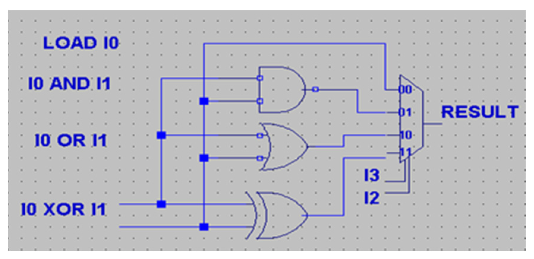
Figure 1. PicoBlaze: the block of logical instructions.
Electronics 14 04600 g001
Figure 2. (a) Truth table of logical functions. (b) The correct VHDL description of a logical instruction-group LUT. (c) The faulty VHDL description of the logical LUT.
Electronics 14 04600 g002
Figure 3. (a) The correct VHDL description of ALU OR LUT. (b) Stuck-at-1 faults one or more inputs or at the output of the LUT.
Electronics 14 04600 g003
Figure 4. The correct truth table of the LUT in the ALU OR circuit and the truth table at the stuck-at-1 fault occurrence at the inputs or outputs of the ALU OR.
Electronics 14 04600 g004
Figure 5. VHDL description of operand_select_mux LUT. The correct one (a) and faulty description (b).
Electronics 14 04600 g005
Figure 6. The kcpsm.vhd and lut.init file examples.
Electronics 14 04600 g006
Figure 7. The flowchart of the fault injection script.
Electronics 14 04600 g007
Figure 8. Cadence NC launch VHDL. The simulator interface (a). The execution of the script progress (b).
Electronics 14 04600 g008
Figure 9. Integration of the developed tool with Xilinx Vivado.
Electronics 14 04600 g009
Figure 10. The VHDL code of the logical instruction LUT: (a) original parameter and (b) faulty parameter.
Electronics 14 04600 g010
Figure 11. VHDL code of arithmetical instruction LUT detector. (a) Original parameter (b) and faulty parameter.
Electronics 14 04600 g011
Figure 12. VHDL code of the shift multiplexer LUT. (a) Original parameter and (b) faulty parameter.
Electronics 14 04600 g012
Figure 13. VHDL description of the flag type LUT. (a) Original parameter and (b) faulty parameter.
Electronics 14 04600 g013
Figure 14. VHDL code of the selected parity function. (a) Original parameter and (b) wrong parameter.
Electronics 14 04600 g014
Table 1. Comparison of fault injection methods.
MethodPublicationPrecisionTimeAdvantageRequirementsCosts DisadvantageFCSEU Mod
Hardware-Based
Radiation Experiment
[3,6,7,9,10,13,25,27,28,29,30]Very lowMediumRealistic results Specific equipmentVery high Uncontrollable fault locations, potentially destructiveLowPhysical
Laser-Based [11,12]High LongRealistic results Laser equipmentMedium/highLimited no. of results,
potentially destructive
Medium/lowPhysical
Emulation-Based[1,2,3,4,5,6,7,8,9,16,18,20,21,23,26,31,32,33,34,35]Up to 83%
Conf. frame-dependent
Low:
several dozen [ms]
Reduced
execution time
FPGA board, host computerHighIntrusive approach, complexLowBitstream modification
Simulation-Based
Sim. Commands
[4,8,9,17,27,36]Up to 100%
Application-dependent
Long:
several dozen hours
Early analysis, full control of injectionsComputer,
simulator SW
LowLong sim. time, high computing resources not compatible with others simulators HighHDL code modification
Simulation-Based
Saboteurs
[9,14,15,19,24]Both application- and no. of saboteur-dependentLong:
several dozen hours
Compatible with all simulatorsComputer,
simulator SW
LowChanged HW and timings HighHDL code modification
Table 2. Achieved fault coverage.
Test ProgramFault Coverage [%]
Stuck-atTotal
883 faults1804 faults
Fibonacci number generator49.933.8
Fibonacci (recursion)56.043.3
Random instruction order62.746.8
MM163.649.9
MM264.451.2
MM366.453.1
Data-sensitive path without full bijective property 72.662.9
Data-sensitive path with full bijectivity88.176.6
Full bijective property with LFSR block for SHIFTs90.384.2
Table 3. List of PicoBlaze functional blocks with the number of injected faults.
PicoBlaze Functional Block# CLB# LUTs# Injected FaultsNumber of
Undetected Faults
Undetected Faults [%]
Basic control11200
Interrupt logic23473880.86
Dec. control PC
CALL/RETURN stack
3610437 35.6
ZERO/CARRY flags6111793217.9
Program Counter102032011 (extended PC),
61 (LFSR solution)
3.4/19.1
Registers and 2nd operand select.51015700
Memory storing function523500
Logical op.592331 0
Shift/Rotate op.611176148
Arithmetical op.61115642.6
ALU MUX91721784 (inputs)38.7
R/W strobes235243 (in/out)82.7
CALL/RETURN stack control6512622 (stack extended)
/60 (for LFSR)
17.9/48.8
SUM731151804x
286 (with in/out)
or 84 without (in/out)
15.8/5.24
Table 4. Types of undetected faults in individual PicoBlaze blocks.
Redundancy
Type
No. Undetected Faults Redundant TermsRedundant
Variables of Terms
Reduced Logical
Terms
Reduced Variables in TermsChanged Variables in Terms
Processor
Block
1. Interrupts logic37198280
2. Decoder for control PC, CALL
/RETURN STACK
38149366
3. ZERO and CARRY flags3174668
4. Program counter1213242
5. Logical operations110000
6. Shift and rotate operations1532343
7. Arithmetical operations411110
8. ALU multiplexer83162951221
9. Read and write strobes422900121
10. CALL/RETURN stack2342872
SUM2869558306043
Table 5. The fault coverage achieved in the bibliography.
PublicationYearMethodDUTNo. Injected FaultsFC [%]
Munoz [14]2020Sim.Counter100098.5
Wegrzyn [4]2021Sim.PicoBlaze180494.75
Ferlini [16]2023Emul.Leon3542572
Zhang [26]2021Emul.FIR299,52015.5
Feng [18]2022Emul.FFT544,12311.18
Zhang [1]2018Emul.c531553,7833.7
Pensec [17]2024Simul.RISC-V48,0062.93
Wilson [32]2021Emul.PicoBlaze318,3481.13
Disclaimer/Publisher’s Note: The statements, opinions and data contained in all publications are solely those of the individual author(s) and contributor(s) and not of MDPI and/or the editor(s). MDPI and/or the editor(s) disclaim responsibility for any injury to people or property resulting from any ideas, methods, instructions or products referred to in the content.