Article

Attitude Control of a Quadcopter UAV Using Sliding Mode Control with an Improved Extended State Observer

1
Yichang Power Supply Company, State Grid Hubei Electric Power Co., Ltd., Yichang 443000, China
2
College of Electrical Engineering and New Energy, China Three Gorges University, Yichang 443002, China
3
Hubei Provincial Key Laboratory for Operation and Control of Cascaded Hydropower Station, Yichang 443002, China
*
Author to whom correspondence should be addressed.
Electronics 2025, 14(22), 4416; https://doi.org/10.3390/electronics14224416
Submission received: 2 October 2025 / Revised: 30 October 2025 / Accepted: 4 November 2025 / Published: 13 November 2025
(This article belongs to the Section Systems & Control Engineering)

Abstract

Quadrotor UAVs require robust control methods to handle complex dynamics, model uncertainties, and external disturbances during trajectory tracking. This paper presents a trajectory tracking control method combining Sliding Mode Control with an Improved Extended State Observer (SMC-IESO). The control system uses a hierarchical structure with position and attitude control loops, employing a third-order Extended State Observer to estimate disturbances in real-time. The improved sliding mode control law incorporates observation error compensation to reduce the required sliding mode gain. Lyapunov stability analysis proves the asymptotic convergence of tracking errors. Simulation results demonstrate that SMC-IESO achieves better tracking accuracy and disturbance rejection than conventional sliding mode control, while significantly reducing control signal chattering, making it more suitable for practical quadrotor applications.

1. Introduction

Quadrotor unmanned aerial vehicles (UAVs) have emerged as versatile platforms for diverse applications including surveillance, aerial photography, precision agriculture, environmental monitoring, search and rescue operations, and logistics delivery. In precision agriculture applications, control inaccuracies and vibrations can lead to uneven pesticide distribution, with spray deviation exceeding 30 cm potentially resulting in crop damage or inadequate pest control. In logistics delivery operations, landing point errors greater than 20 cm can cause package damage or mission failure, particularly in confined urban environments. These practical challenges underscore the critical need for robust, high-precision trajectory tracking control that can maintain stable flight performance under variable wind conditions and payload changes. Their structural simplicity, cost-effectiveness, vertical take-off and landing (VTOL) capability, and hovering stability have driven widespread adoption across military and civilian sectors [1,2].
The control of quadrotor UAVs presents significant challenges due to their inherent characteristics as underactuated, strongly coupled nonlinear systems. With six degrees of freedom but only four control inputs, quadrotors exhibit complex dynamics where translational and rotational motions are inherently coupled [3]. Furthermore, practical flight operations subject these vehicles to various uncertainties including atmospheric disturbances [4], payload variations, modeling errors, and actuator dynamics, which degrade tracking performance and compromise flight safety [5,6].
Various control strategies have been developed to address these challenges. Proportional-integral-derivative (PID) control remains popular due to its simplicity but exhibits limited robustness against uncertainties and disturbances [7]. Feedback linearization techniques require accurate system models and demonstrate sensitivity to unmodeled dynamics [8,9]. Adaptive control methods can accommodate parameter variations but suffer from slow convergence rates under rapid parameter changes [10,11].
Sliding mode control (SMC) has attracted considerable attention for quadrotor applications due to its inherent robustness to matched uncertainties [12,13]. However, the discontinuous control action in conventional SMC induces chattering, which degrades performance and may damage actuators. While higher-order sliding modes [14] and boundary layer techniques [15] can reduce chattering, they typically compromise robustness.
Active Disturbance Rejection Control (ADRC) inherits many advantages of Proportional-Integral-Derivative (PID) control, leading to its great success [16]: its control principle is error-driven rather than model-based; it draws on the best achievements of modern control theory—state observers; it fully utilizes the power of nonlinear feedback and makes it function effectively; as a promising method, ADRC treats internal dynamics and external disturbances as a combined “total disturbance”, and estimates and compensates it through the Extended State Observer (ESO) [16,17]. ADRC provides an operation mode without a model, effective disturbance rejection, and robust performance, making it increasingly popular in quadrotor control [18,19].
The reduced-order extended state observer (Reduced-Order ESO, RESO) has been proposed and has demonstrated advantages in various control scenarios. For instance, in the vibration control of fully clamped plates, the combination of SMC and RESO is adopted. By reducing the observer order, the computational burden is effectively reduced and the system’s anti-noise ability is enhanced. In the integrated guidance and control (IGC) design of hypersonic missiles, RESO is introduced to estimate the system’s lumped disturbances and perform feedforward compensation within the backstepping control framework, significantly improving the interception accuracy and robustness against maneuvering targets. However, RESO requires an accurate model of the controlled object [20,21].
Despite their individual merits, both SMC and ADRC have limitations. ESO performance is constrained by bandwidth limitations and phase lag, while SMC suffers from chattering. Recent research has explored combining these approaches to leverage their complementary advantages [22,23].
This paper presents a robust trajectory tracking control method for quadrotor UAVs that integrates sliding mode control with an improved extended state observer (SMC-IESO). The main contributions are:
(1)
An improved sliding mode control law incorporating observation error compensation is developed. By introducing position observation error feedback and exploiting the relationship between observation and disturbance estimation errors, the proposed method reduces the required sliding gain, effectively suppressing chattering while maintaining robustness.
(2)
A hierarchical control architecture is designed that exploits the time-scale separation between translational and rotational dynamics, decomposing the six-DOF tracking problem into cascaded position and attitude control loops.
(3)
Rigorous stability analysis based on Lyapunov theory establishes the asymptotic stability of the closed-loop system, providing theoretical guarantees for practical implementation.
The remainder of this paper is organized as follows. Section 2 presents the quadrotor dynamic model and formulates the control problem. Section 3 details the SMC-IESO controller design for altitude, position, and attitude control. Section 4 presents simulation results and performance analysis. Section 5 concludes the paper and discusses future work.

2. System Modeling and Problem Description

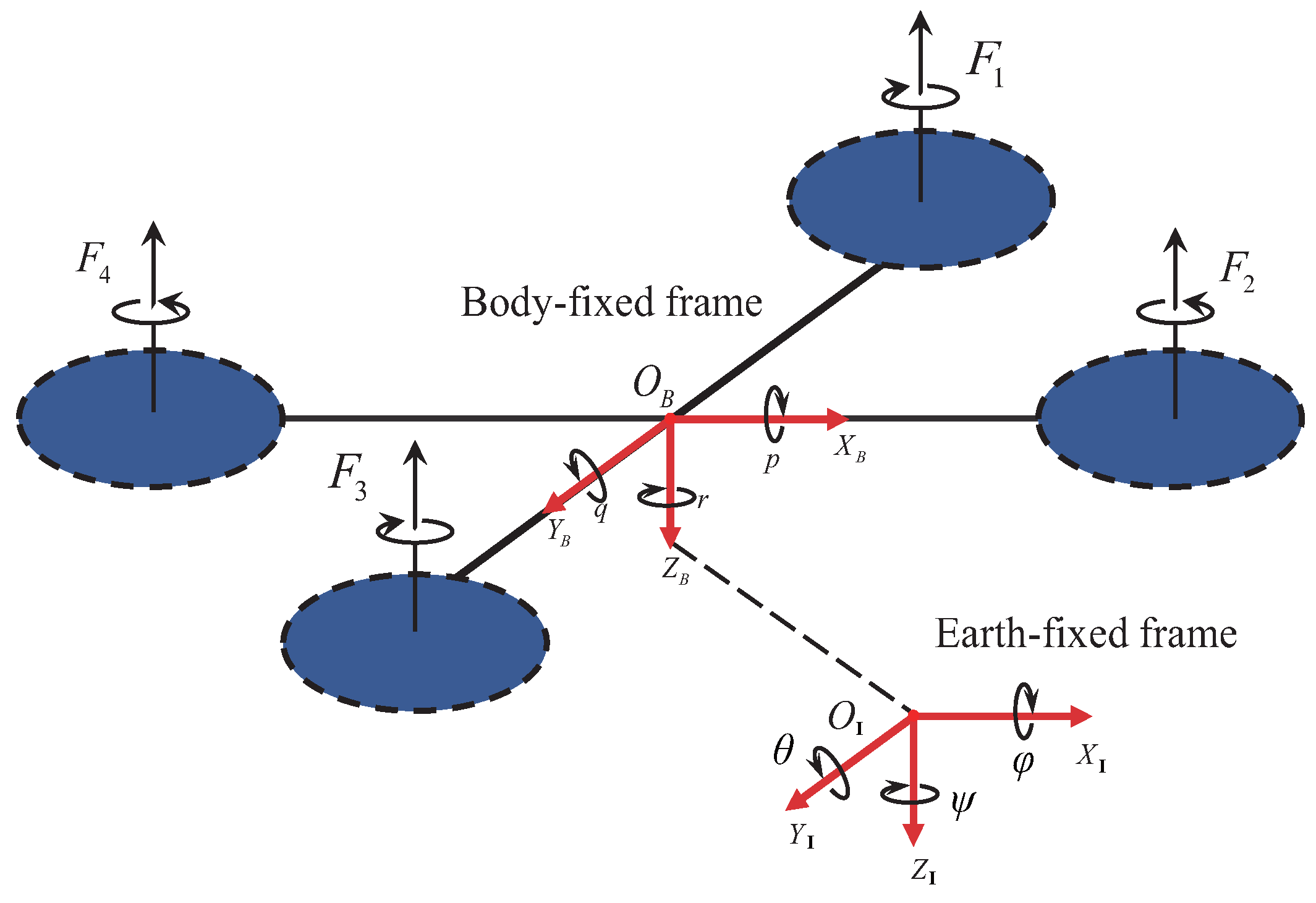
The motion of a quadrotor UAV can be described in both the earth fixed frame F I = { O I , X I , Y I , Z I } and the body fixed frame F B = { O B , X B , Y B , Z B } . As shown in Figure 1, F I is used to describe global position and attitude, while F B is used to analyze the body’s motion state and forces.
The position and velocity of the UAV in the inertial coordinate frame F I are represented as p = [ x , y , z ] T R 3 and v = [ v x , v y , v z ] T , respectively. The attitude is represented using Euler angles, i.e., η = [ ϕ , θ , ψ ] T , corresponding to roll, pitch, and yaw angles. The angular velocity in the body coordinate frame is denoted as ω = [ p , q , r ] T .
Assuming the UAV is a rigid body with mass m and inertia matrix I = diag ( I x , I y , I z ) , the system’s dynamic model includes both translational and rotational parts, with dynamics described as follows:
p ˙ = v m v ˙ = m g + R ( η ) f B + d f η ˙ = W ( η ) ω I ω ˙ = u τ ω × ( I ω ) + d τ
where g = [ 0 , 0 , g ] T represents the gravitational acceleration vector, R ( η ) is the rotation matrix from body to inertial coordinate frame, f B = [ 0 , 0 , u 1 ] T represents the total thrust vector in the body coordinate frame, d f = [ d f x , d f y , d f z ] T is the translational disturbance (such as gusts and external forces), u τ = [ u 2 , u 3 , u 4 ] T is the control torque in the body coordinate frame, and d τ = [ d τ x , d τ y , d τ z ] T is the rotational disturbance. In this paper, it is assumed that d f , d ˙ f , d τ , and d ˙ τ are all bounded.
The relationship between Euler angles and angular velocities is described by the transformation matrix W ( η ) , which takes the form:
W ( η ) = 1 sin ϕ tan θ cos ϕ tan θ 0 cos ϕ sin ϕ 0 sin ϕ / cos θ cos ϕ / cos θ
Remark 1
(Singularity Avoidance). In this work, it is assumed that the quadrotor performs regular flight tasks, with attitude angles satisfying ϕ , θ ( π 2 , π 2 ) , thus ensuring cos ϕ cos θ 0 and avoiding the control singularity problem.
The relationship between the rotational speed ω i of the i-th rotor of the quadrotor and the resulting thrust and torques is as follows:
u 1 = b ( ω 1 2 + ω 2 2 + ω 3 2 + ω 4 2 ) u 2 = l b ( ω 4 2 ω 2 2 ) u 3 = l b ( ω 3 2 ω 1 2 ) u 4 = d ( ω 1 2 ω 2 2 + ω 3 2 ω 4 2 )
Expanding Equation (1), the state-space expression of the system can be obtained:
x ˙ = v x y ˙ = v y z ˙ = v z v ˙ x = u 1 m ( cos ϕ sin θ cos ψ + sin ϕ sin ψ ) + d f x m v ˙ y = u 1 m ( cos ϕ sin θ sin ψ sin ϕ cos ψ ) + d f y m v ˙ z = u 1 m ( cos ϕ cos θ ) g + d f z m ϕ ˙ = p + q sin ϕ tan θ + r cos ϕ tan θ θ ˙ = q cos ϕ r sin ϕ ψ ˙ = q sin ϕ + r cos ϕ cos θ p ˙ = I y I z I x q r + 1 I x u 2 + 1 I x d τ x q ˙ = I z I x I y p r + 1 I y u 3 + 1 I y d τ y r ˙ = I x I y I z p q + 1 I z u 4 + 1 I z d τ z
The variables and their physical meanings are listed in Table 1.
This research focuses on robust trajectory tracking control of the quadrotor UAV in the presence of unknown disturbances d f , d τ . The control objective is described as:
lim t p p * η η * = 0
where p * ( t ) = [ x d , y d , z d ] T and η * = [ ϕ d , θ d , ψ d ] T are the desired position and attitude angles, respectively. To achieve this objective, this paper proposes a hierarchical control structure with inner and outer loops, which will be detailed in the next section.

3. Control System Design

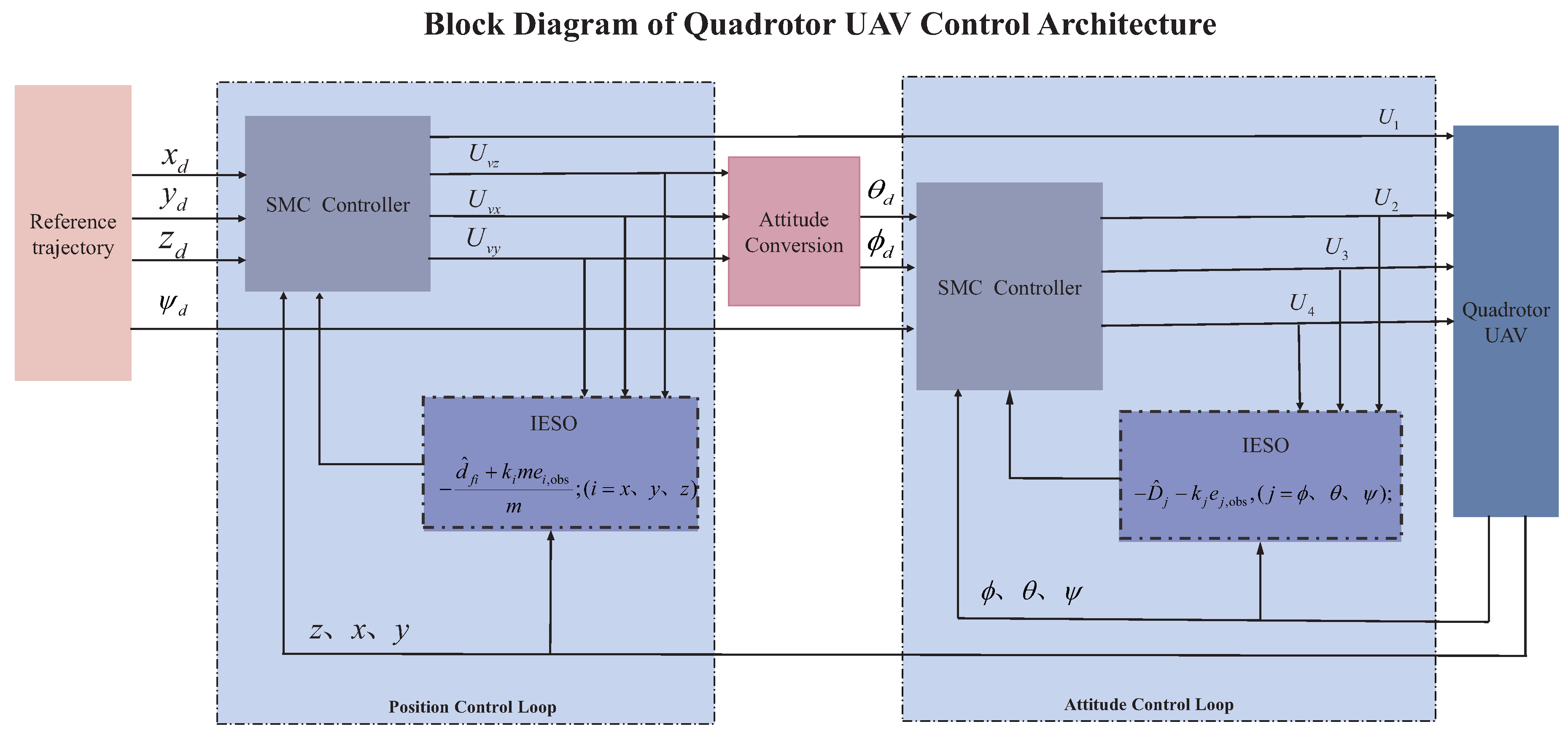
For the strongly coupled nonlinear system with disturbances described by Equation (1), we propose a hierarchical control architecture comprising position and attitude control loops. As shown in Figure 2, The position loop employs the SMC-IESO method to estimate and compensate for composite disturbances in real-time, while the attitude loop utilizes SMC-IESO to track the desired attitude commands generated by the position controller. This hierarchical structure exploits the time-scale separation between translational and rotational dynamics, enhancing both disturbance rejection and trajectory tracking performance.

3.1. Vertical Channel Controller Analysis and Design

The vertical direction of the quadrotor is affected by the coupled action of main rotor force, gravity, and external disturbances (such as airflow, load changes, etc.), with its dynamic model expressed as:
z ˙ = v z v ˙ z = u 1 m cos ϕ cos θ g + d f z m
Given the desired altitude trajectory z d ( t ) and its derivatives z ˙ d ( t ) and z ¨ d ( t ) , the altitude tracking error and its first-order derivative are defined as:
e z = z z d e ˙ z = v z z ˙ d
To achieve robust precise tracking in the closed-loop system, the following sliding surface is constructed based on sliding mode control theory:
s z = c z e z + e ˙ z
where c z > 0 is the sliding mode parameter, the magnitude of which determines the convergence speed and dynamic performance of the closed-loop error.
For the controlled object in Equation (6), a traditional sliding mode control law is designed with the following structure:
u 1 , SMC = m cos ϕ cos θ g + z ¨ d c z e ˙ z k z s sign ( s z )
where k z s > 0 is the sliding mode gain, used to ensure the system’s robustness against matched disturbances. The switching term sign ( s z ) can effectively suppress the influence of system internal uncertainties and matched disturbances. However, the sliding mode controller in Equation (9) tends to produce chattering phenomena in practical applications, and its ability to suppress parameter perturbations and unmodeled external disturbances is limited.
To address these shortcomings, this paper employs a third-order Extended State Observer (ESO) in the quadrotor’s vertical channel to accurately estimate the three state variables { z , v z , d f z } .
Specifically, the ESO design is:
z ^ ˙ = v ^ z + β z 1 ( z z ^ ) v ^ ˙ z = u 1 m cos ϕ cos θ g + d ^ f z m + β z 2 ( z z ^ ) d ^ ˙ f z = β z 3 ( z z ^ )
where z ^ , v ^ z , d ^ f z are the estimated values of altitude, velocity, and disturbance, respectively, and β z 1 , β z 2 , β z 3 > 0 are the ESO observer gains.
To analyze the disturbance suppression performance, the observation errors are defined as:
e z , obs = z z ^ e v z , obs = v z v ^ z e d f z , obs = d f z d ^ f z
Combining Equations (6) and (10), the observer error dynamic equations can be expressed as:
e ˙ z , obs = e v z , obs β z 1 e z , obs e ˙ v z , obs = e d f z , obs m β z 2 e z , obs e ˙ d f z , obs = d ˙ f z β z 3 e z , obs
From the second equation in (12), we can derive:
e d f z , obs = m e ˙ v z , obs + m β z 2 e z , obs
It can be observed that e d f z , obs contains e z , obs , and e z , obs is directly obtainable, so the disturbance estimation error can be reduced through e z , obs . Based on this, this paper designs an improved active disturbance rejection sliding mode control law:
u 1 = u 1 , SMC d ^ f z + k z m e z , obs cos ϕ cos θ
This control law introduces an observation error compensation term k z m e z , obs , utilizing the relationship in Equation (13) to adjust and reduce the disturbance suppression error, thus allowing for a smaller sliding mode gain design, which in turn reduces the chattering phenomenon.

3.1.1. Observer Convergence Analysis

To analyze the convergence characteristics of the observer, define the observation error vector:
e obs = e z , obs e v z , obs e d f z , obs
According to Equations (10), (11) and (14), the observation error dynamic equation can be written in matrix form:
e ˙ obs = A obs e obs + B obs d ˙ f z
where:
A obs = β z 1 1 0 β z 2 + k z 0 1 m β z 3 0 0 , B obs = 0 0 1
The characteristic polynomial of matrix A obs is:
det ( λ I A obs ) = λ 3 + β z 1 λ 2 + ( β z 2 k z ) λ + β z 3 m
According to the Routh-Hurwitz stability criterion, the observer is asymptotically stable when the following conditions are satisfied:
β z 1 > 0 β z 2 k z > 0 β z 3 m > 0 β z 1 ( β z 2 k z ) > β z 3 m
Performing a Laplace transform on the above system, we can obtain the transfer function from the disturbance derivative d ˙ f z to the disturbance observation error e d f z , obs :
G ( s ) = s 2 + β z 1 s + ( β z 2 k z ) s 3 + β z 1 s 2 + ( β z 2 k z ) s + β z 3 m
It can be found that when k z ( 0 , β z 2 ) , the transfer function (20) has the following dynamic characteristics: (1) For low-frequency disturbances ( s 0 ): G ( s ) m ( β z 2 k z ) β z 3 . Compared to the traditional ESO method ( k z = 0 ), the IESO method further reduces the disturbance estimation error; (2) For high-frequency disturbances ( s ): G ( s ) 1 s , the IESO method has similar characteristics to the traditional ESO method; (3) Stability condition: When k z ( 0 , β z 2 ) , the roots of the characteristic polynomial (18) remain in the left half-plane, satisfying the Routh-Hurwitz criterion, without affecting the stability of the system.

3.1.2. Closed-Loop System Stability

Considering the dynamic characteristics of the sliding surface, select a quadratic Lyapunov function:
V z = 1 2 s z 2
Taking the derivative of Equation (21) and combining with the sliding surface definition in Equation (8), we get:
V ˙ z = s z s ˙ z = s z ( c z e ˙ z + e ¨ z ) = s z c z e ˙ z + z ¨ z ¨ d
Substituting the vertical channel dynamics from Equation (6), we obtain:
V ˙ z = s z c z e ˙ z + u 1 m cos ϕ cos θ g + d f z m z ¨ d
Substituting the improved active disturbance rejection sliding mode control law from Equation (14), we obtain:
u 1 = m cos ϕ cos θ g + z ¨ d c z e ˙ z k z s sign ( s z ) d ^ f z + k z m e z , obs cos ϕ cos θ
Substituting Equation (24) into Equation (23), we obtain:
V ˙ z = s z c z e ˙ z + g + z ¨ d c z e ˙ z k s z sign ( s z ) d ^ f z m k z e z , obs g + d f z m z ¨ d = s z k s z sign ( s z ) + d f z d ^ f z m k z e z , obs = s z k s z sign ( s z ) + e d f z , obs m k z e z , obs
Substituting Equation (13) into the above, we obtain:
V ˙ z = s z k s z sign ( s z ) + m e ˙ v z , obs + m β z 2 e z , obs m k z e z , obs = s z k s z sign ( s z ) + e ˙ v z , obs + β z 2 e z , obs k z e z , obs = k s z | s z | + s z [ e ˙ v z , obs + ( β z 2 k z ) e z , obs ]
Based on the above analysis, when the observer parameters satisfy the stability conditions in Equation (19), the observation error e v z , obs and its derivative e ˙ v z , obs are bounded. Therefore, there exists a finite time T > 0 such that when t > T , we have:
| e ˙ v z , obs + ( β z 2 k z ) e z , obs | ϵ
where ϵ > 0 .
By substituting Equation (27) into Equation (26), when the sliding mode gain is chosen to satisfy k s z > ϵ , we have:
V ˙ z = k z | s z | + s z [ e ˙ v z , obs + ( β z 2 k z ) e z , obs ] k z | s z | + | s z | ϵ = ( k z ϵ ) | s z | < 0 , s z 0
This indicates that the Lyapunov function V z is strictly decreasing, and according to Lyapunov stability theory, the sliding surface s z will converge to zero in finite time, meaning the system states will reach the sliding surface and slide on it.
Once the system reaches the sliding surface s z = 0 , according to Equation (8), we have:
c z e z + e ˙ z = 0
The solution to which is:
e z ( t ) = e z ( 0 ) e c z t
This indicates that the altitude tracking error e z converges to zero at an exponential rate.
In summary, under the premise of satisfying the observer stability conditions in Equation (19) and the sliding mode gain condition k s z > ϵ , the proposed SMC-IESO control strategy can ensure the asymptotic stability of the quadrotor’s vertical channel, achieving precise tracking of the desired altitude trajectory.
Remark 2
(Performance Enhancement). Compared to traditional sliding mode control, the SMC-IESO strategy significantly reduces the required sliding mode gain k s z through real-time observation and compensation of disturbances, thereby effectively mitigating the chattering phenomenon in control signals and improving the practicality of the control system.

3.2. x and y Axis Indirect IESO-SMC Control Strategy

Based on the design approach of the vertical channel controller, this section develops the analysis for the horizontal position control problem of the quadrotor UAV. Unlike the vertical channel, the position control of the x and y axes needs to be indirectly realized through adjusting the attitude angles (roll angle ϕ and pitch angle θ ), which increases the complexity and coupling of the system.
The dynamics equations of the quadrotor in the horizontal direction can be extracted from Equation (4):
x ˙ = v x y ˙ = v y v ˙ x = u 1 m ( cos ϕ sin θ cos ψ + sin ϕ sin ψ ) + d f x m v ˙ y = u 1 m ( cos ϕ sin θ sin ψ sin ϕ cos ψ ) + d f y m
Given the desired position trajectories x d , y d and their derivatives, the horizontal position tracking errors are defined as:
e x = x x d e y = y y d e ˙ x = v x x ˙ d e ˙ y = v y y ˙ d
Considering the indirect nature of horizontal position control, this paper adopts a two-step design method based on virtual control. First, the horizontal accelerations x ¨ and y ¨ are viewed as virtual control inputs, and the position loop control law is designed; then, the desired attitude angle commands are generated through the mapping relationship between virtual control and actual attitude angles.

3.2.1. Position Loop Virtual Control Design

To achieve robust tracking of horizontal positions, the following sliding surfaces are constructed:
s x = c x e x + e ˙ x s y = c y e y + e ˙ y
where c x , c y > 0 are sliding mode parameters.
For the composite disturbances in the horizontal direction, third-order extended state observers are designed to estimate the states and disturbances in both the x and y channels:
x ^ ˙ = v ^ x + β x 1 ( x x ^ ) v ^ ˙ x = u v x + d ^ f x m + β x 2 ( x x ^ ) d ^ ˙ f x = β x 3 ( x x ^ )
y ^ ˙ = v ^ y + β y 1 ( y y ^ ) v ^ ˙ y = u v y + d ^ f y m + β y 2 ( y y ^ ) d ^ ˙ f y = β y 3 ( y y ^ )
where u v x and u v y are the virtual control inputs for the x and y directions, respectively, and β x 1 , β x 2 , β x 3 and β y 1 , β y 2 , β y 3 are the observer gain parameters.
Similar to the analysis of the vertical channel, the observation errors are defined as:
e x , obs = x x ^ , e y , obs = y y ^ e v x , obs = v x v ^ x , e v y , obs = v y v ^ y e d f x , obs = d f x d ^ f x , e d f y , obs = d f y d ^ f y
Based on the disturbance observation results, an improved active disturbance rejection sliding mode virtual control law is designed:
u v x = x ¨ d c x e ˙ x k x s sign ( s x ) d ^ f x + k x m e x , obs m u v y = y ¨ d c y e ˙ y k y s sign ( s y ) d ^ f y + k y m e y , obs m
where k x s , k y s > 0 are sliding mode gains, and k x , k y > 0 are observation error compensation gains.

3.2.2. Attitude Angle Command Generation

The relationship between the virtual control inputs u v x and u v y and the actual control inputs is established. From Equation (31), we know:
u v x = u 1 m ( cos ϕ sin θ cos ψ + sin ϕ sin ψ ) u v y = u 1 m ( cos ϕ sin θ sin ψ sin ϕ cos ψ )
Through inverse operations, the desired attitude angle commands can be obtained:
ϕ d = arcsin m ( u v x sin ψ u v y cos ψ ) u 1 θ d = arctan u v x cos ψ + u v y sin ψ ( g + u v z )
where u v z is the virtual control input in the vertical direction, which has been determined in the previous section as:
u v z = z ¨ d c z e ˙ z k z s sign ( s z ) d ^ f z + k z m e z , obs m

3.2.3. Stability Analysis

Choose the Lyapunov function:
V x y = 1 2 ( s x 2 + s y 2 )
Taking the derivative of V x y and combining with the virtual control law (37), we get:
V ˙ x y = s x s ˙ x + s y s ˙ y = s x ( c x e ˙ x + e ¨ x ) + s y ( c y e ˙ y + e ¨ y ) = s x c x e ˙ x + x ¨ x ¨ d + s y c y e ˙ y + y ¨ y ¨ d
By substituting the dynamics equations (31) and the virtual control law (37), following a derivation process similar to that of the vertical channel, when the observer parameters satisfy the corresponding stability conditions, it can be proven that:
V ˙ x y ( k x s ϵ x ) | s x | ( k y s ϵ y ) | s y | < 0
where ϵ x , ϵ y > 0 .
Therefore, when the sliding mode gains are chosen to satisfy k x s > ϵ x and k y s > ϵ y , the horizontal position tracking errors will converge exponentially to zero.
Remark 3
(Attitude Angle Constraints). In practical applications, to ensure the flight safety and control effectiveness of the quadrotor, the desired attitude angles ϕ d and θ d should satisfy the constraint conditions | ϕ d | , | θ d | ϕ max , where ϕ max is the maximum allowable attitude angle. When the calculated desired attitude angles exceed the constraint range, saturation processing should be performed.
Remark 4
(Hierarchical Control Architecture). By transforming horizontal position control into attitude angle commands, a hierarchical design of position outer loop and attitude inner loop is achieved. This structure fully utilizes the multi-time-scale characteristics of the quadrotor system, simplifies controller design, and ensures good tracking performance.
Remark 5
(Disturbance Compensation Mechanism). The IESO in the horizontal direction not only observes external disturbances but also compensates for modeling errors and parameter uncertainties to a certain extent. Through real-time disturbance estimation and feedforward compensation, the system’s robustness is significantly improved.

3.3. Attitude Inner Loop IESO-SMC Control

The attitude inner loop, as a key component of the hierarchical control system, is mainly responsible for tracking the desired attitude commands ϕ d , θ d generated by the position outer loop and the externally assigned yaw angle ψ d . The attitude inner loop has fast dynamic response capabilities, providing strong support for the quadrotor to achieve high-precision trajectory tracking.
According to the system state equations (4), the dynamic model of the attitude subsystem can be extracted:
ϕ ˙ = p + q sin ϕ tan θ + r cos ϕ tan θ , θ ˙ = q cos ϕ r sin ϕ ψ ˙ = q sin ϕ + r cos ϕ cos θ p ˙ = I y I z I x q r + 1 I x u 2 + 1 I x d τ x q ˙ = I z I x I y p r + 1 I y u 3 + 1 I y d τ y r ˙ = I x I y I z p q + 1 I z u 4 + 1 I z d τ z
The attitude tracking errors and their first-order derivatives are defined as follows:
e ϕ = ϕ ϕ d , e ˙ ϕ = ϕ ˙ ϕ ˙ d e θ = θ θ d , e ˙ θ = θ ˙ θ ˙ d e ψ = ψ ψ d , e ˙ ψ = ψ ˙ ψ ˙ d
Considering the strong coupling nonlinearity, parameter perturbations, and disturbances of the attitude dynamics, the gyroscopic torque terms and external disturbances are unified as composite disturbances:
D ϕ = I y I z I x q r + 1 I x d τ x D θ = I z I x I y p r + 1 I y d τ y D ψ = I x I y I z p q + 1 I z d τ z
Thus, the attitude subsystem can be rewritten as:
ϕ ¨ = 1 I x u 2 + D ϕ θ ¨ = 1 I y u 3 + D θ ψ ¨ = 1 I z u 4 + D ψ

3.3.1. Sliding Surface and ESO Design

For the three channels of attitude, sliding surfaces are constructed:
s ϕ = c ϕ e ϕ + e ˙ ϕ s θ = c θ e θ + e ˙ θ s ψ = c ψ e ψ + e ˙ ψ
where c ϕ , c θ , c ψ > 0 are sliding mode parameters.
To eliminate various disturbances in the attitude channels, third-order extended state observers are designed (taking the ϕ channel as an example):
ϕ ^ ˙ = ϕ ˙ ^ + β ϕ 1 ( ϕ ϕ ^ ) ϕ ˙ ^ ˙ = u 2 I x + D ^ ϕ + β ϕ 2 ( ϕ ϕ ^ ) D ^ ˙ ϕ = β ϕ 3 ( ϕ ϕ ^ )
where β ϕ 1 , β ϕ 2 , β ϕ 3 > 0 are ESO gains. Similarly, ESOs are designed for the pitch and yaw channels.
The observation errors for each channel are defined as:
e ϕ , obs = ϕ ϕ ^ , e ϕ ˙ , obs = ϕ ˙ ϕ ˙ ^ , e D ϕ , obs = D ϕ D ^ ϕ e θ , obs = θ θ ^ , e θ ˙ , obs = θ ˙ θ ˙ ^ , e D θ , obs = D θ D ^ θ e ψ , obs = ψ ψ ^ , e ψ ˙ , obs = ψ ˙ ψ ˙ ^ , e D ψ , obs = D ψ D ^ ψ

3.3.2. Improved Active Disturbance Rejection Sliding Mode Control Law

Based on the sliding surface and extended state observation, the following attitude inner loop improved active disturbance rejection sliding mode controller is proposed:
u 2 = I x ϕ ¨ d c ϕ e ˙ ϕ k ϕ s sign ( s ϕ ) D ^ ϕ k ϕ e ϕ , obs u 3 = I y θ ¨ d c θ e ˙ θ k θ s sign ( s θ ) D ^ θ k θ e θ , obs u 4 = I z ψ ¨ d c ψ e ˙ ψ k ψ s sign ( s ψ ) D ^ ψ k ψ e ψ , obs
where k ϕ s , k θ s , k ψ s > 0 are sliding mode gains, and k ϕ , k θ , k ψ > 0 are observation error compensation coefficients. This structure utilizes real-time disturbance estimation and error compensation mechanisms to effectively enhance tracking robustness and reduce chattering.

3.3.3. Closed-Loop Stability Analysis

Select the Lyapunov function:
V att = 1 2 s ϕ 2 + s θ 2 + s ψ 2
Taking the derivative of V att and combining the simplified attitude dynamics and control law (51), we have:
V ˙ att ( k ϕ s ϵ ϕ ) | s ϕ | ( k θ s ϵ θ ) | s θ | ( k ψ s ϵ ψ ) | s ψ | < 0
where ϵ ϕ , ϵ θ , ϵ ψ > 0 are observation error convergence margins. When k ϕ s > ϵ ϕ , k θ s > ϵ θ , k ψ s > ϵ ψ , V att is strictly decreasing, and the attitude tracking errors will converge exponentially to zero.
Remark 6
(Multi-channel Decoupling and Robustness). The attitude inner loop adopts independent ESO observation and sliding mode compensation design for each channel, simultaneously providing good dynamic compensation effects for coupling, disturbances, and parameter changes.
Remark 7
(Multi-time-scale Fast Response). Utilizing the fast time-scale characteristics of the attitude inner loop, the attitude closed-loop under the hierarchical structure can provide a high-quality response base for position trajectory tracking.
Remark 8
(Sliding Mode Gain Optimization). After introducing observation error compensation, the sliding mode gain can be significantly reduced, thereby effectively mitigating control signal chattering and enhancing engineering practicality.
Remark 9
(Time-scale Separation). The hierarchical control structure adopted in this paper fully utilizes the time-scale separation characteristics of the quadrotor system. The time constant of the position outer loop is typically on the order of seconds, while the time constant of the attitude inner loop is on the order of milliseconds. This significant time-scale difference provides a theoretical basis for the hierarchical control design.
In summary, the hierarchical robust control architecture proposed in this section, through the SMC-IESO position control of the outer loop and the fast sliding mode attitude control of the inner loop, effectively solves the trajectory tracking problem of quadrotor UAVs. This control strategy not only handles the strong nonlinearity and coupling characteristics of the system but also effectively suppresses the influence of various external disturbances, providing theoretical support for high-precision control of quadrotor UAVs.

3.4. Parameter Design Methodology

(1)
ESO Parameter Selection (Bandwidth Method) The ESO gains are selected using the bandwidth parameterization method [17]. For a third-order ESO, the observer gains can be expressed as: β 1 = 3 ω 0 , β 2 = 3 ω 0 2 , β 3 = ω 0 3 .
(2)
Error Compensation Gain Selection The error compensation gains ( k x , y , z , k ϕ , θ , ψ ) are selected through iterative tuning: According to Equation (20) matching observation gain.

4. Simulation Verification

To verify the effectiveness of the proposed SMC-IESO hierarchical control method, numerical simulations are conducted using MATLAB 2022b. The physical parameters of the quadrotor used in the simulation are shown in Table 2.

4.1. Simulation Scenario Setup

To fully verify the tracking performance and disturbance rejection capability of the controller during complex maneuvers, a three-dimensional spiral trajectory is designed as the reference trajectory, with the yaw angle required to undergo sinusoidal variations. The specific trajectory parameters are as follows:
x d ( t ) = R cos ( ω s t ) y d ( t ) = R sin ( ω s t ) z d ( t ) = 1 + h r t ψ d ( t ) = A ψ sin ( 2 π f ψ t )
where R = 2.5 m is the spiral radius, ω s = 0.4 rad/s is the spiral angular frequency, h r = 0.3 m/s is the ascent rate, A ψ = 0.6 rad is the yaw angle amplitude, and f ψ = 0.3 Hz is the yaw angle frequency. This trajectory design encompasses complex three-dimensional maneuvers, including horizontal circular motion, vertical climbing, and yaw angle variations, which can comprehensively test the performance of the control system.
To test the disturbance rejection performance of the controller, the following periodic disturbances are applied to the system:
d f i = A f i sin ( 2 π f f i t + ϕ f i ) , i = x , y , z d τ i = A τ i sin ( 2 π f τ i t + ϕ τ i ) , i = ϕ , θ , ψ
where the translational disturbance amplitudes are A f = [ 0.5 , 0.4 , 0.3 ] T N, frequencies f f = [ 0.6 , 0.8 , 0.4 ] T Hz, phases ϕ f = [ 0 , π / 3 , π / 6 ] T rad; the rotational disturbance amplitudes are A τ = [ 0.08 , 0.08 , 0.05 ] T N·m, frequencies f τ = [ 1.0 , 0.7 , 0.5 ] T Hz, phases ϕ τ = [ π / 4 , π / 2 , 0 ] T rad. These disturbances cover different frequency ranges, and each axis has both translational and rotational perturbations of different amplitudes. Therefore, the final disturbance acting on the aircraft is a composite type of disturbance.
The controller parameter settings are shown in Table 3.
The simulation time is set to 60 s, with an integration step size of 0.001 s, ensuring the accuracy of numerical calculations. To avoid attitude angle singularity, the maximum roll and pitch angle constraints are set to ± 80 . The initial position of the quadrotor is set to ( 0 , 0 , 0.5 ) m, with initial attitude angles and angular velocities all zero.

4.2. Simulation Results Analysis

4.2.1. Trajectory Tracking Performance

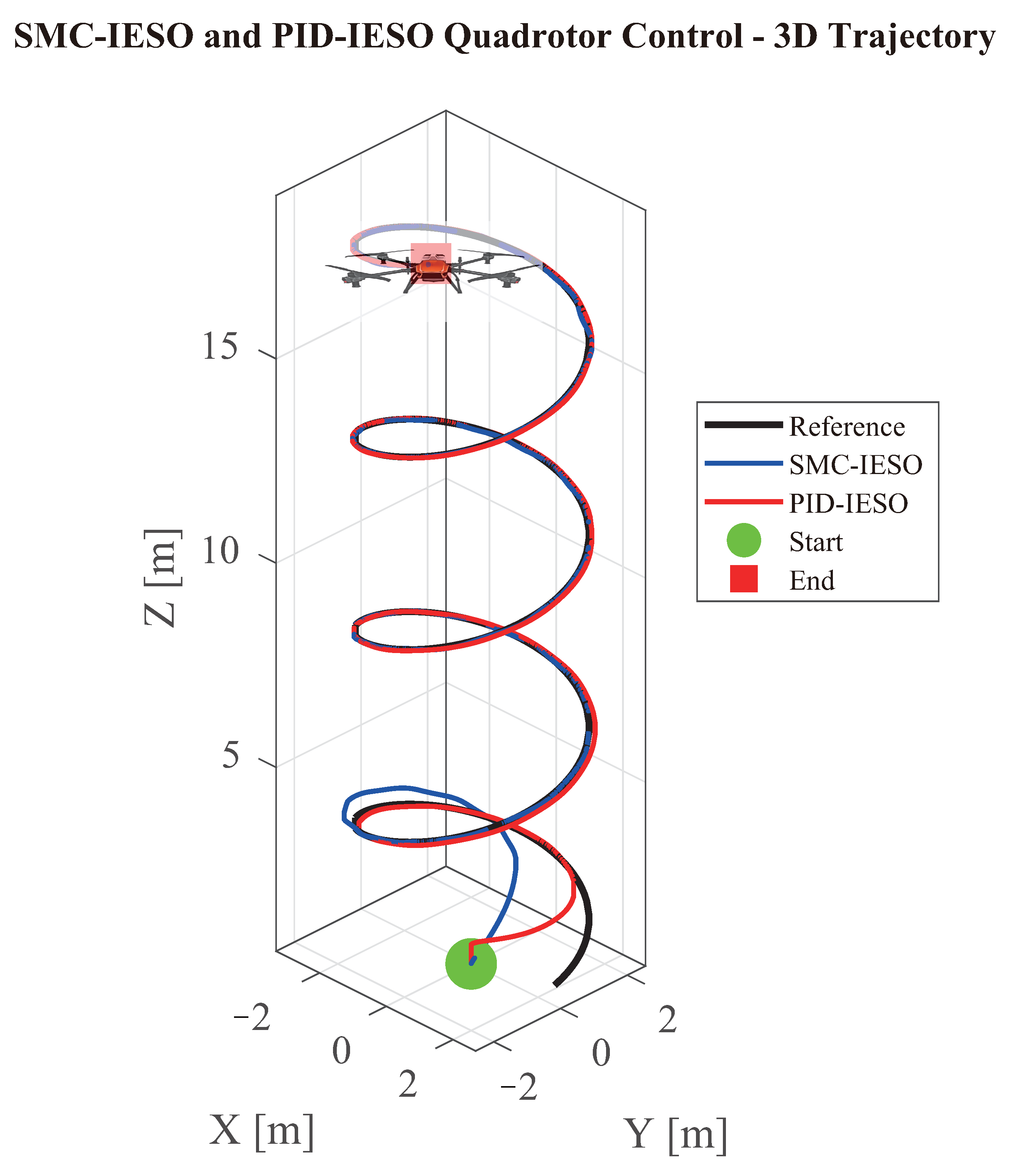
Figure 3 shows the overall control performance of the quadrotor. From the three-dimensional trajectory graph, it can be seen that despite the presence of complex external disturbances, the actual trajectory can still track the desired spiral trajectory well, verifying the effectiveness of the proposed control method.
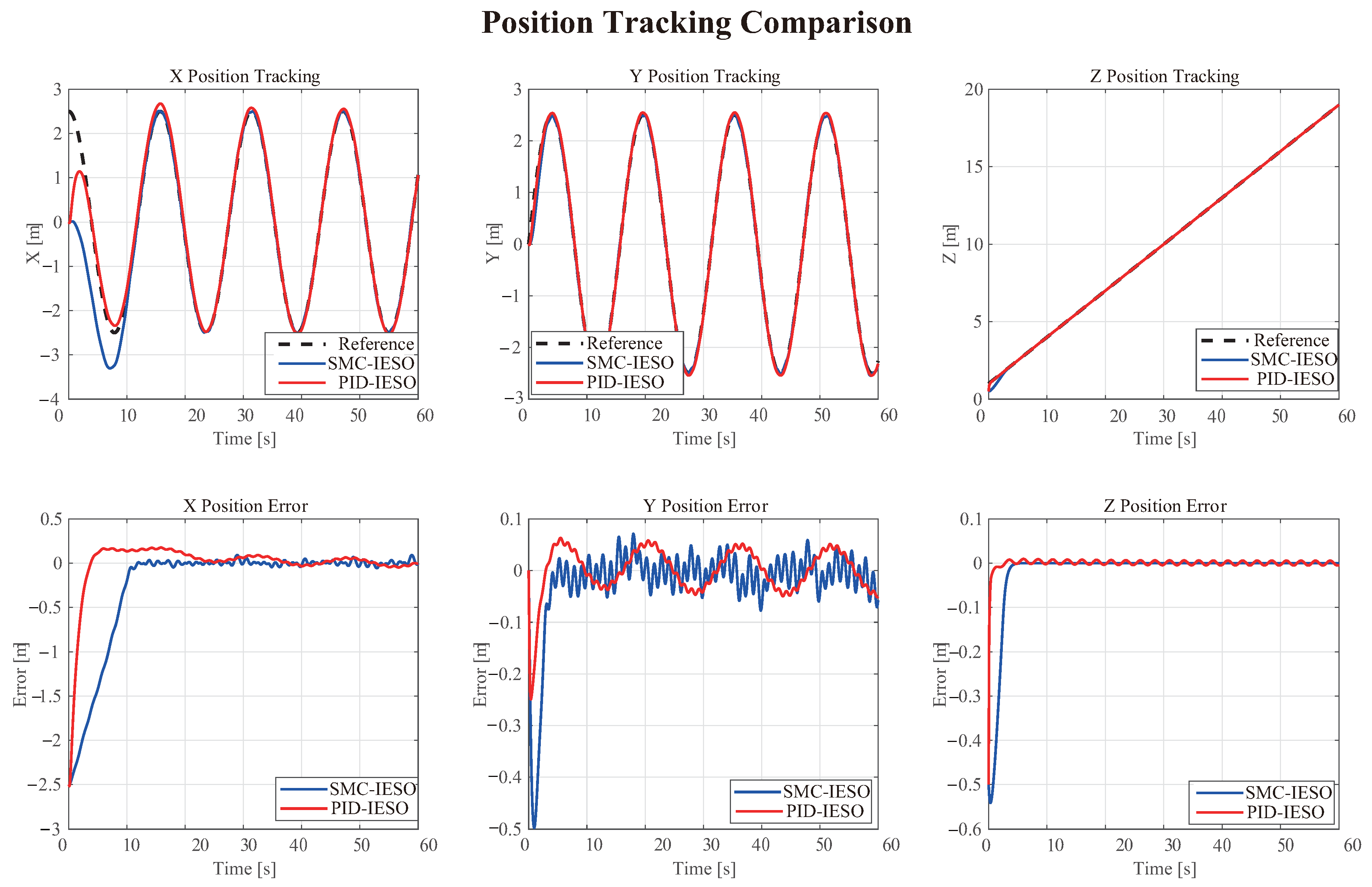
The position tracking results in Figure 4 indicate that this system can quickly track complex three-dimensional trajectories. The X-axis and Y-axis show standard sine and cosine variations, while the Z-axis achieves a stable linear increase. From the position tracking error curve, it can be seen that the error of SMC-IESO is smaller than that of PID-IESO, and the position errors in all three directions converge to within ± 0.1 m. The tracking errors of the X-axis and Y-axis are slightly larger than that of the Z-axis, because in the horizontal direction, changing the posture angle is required to achieve more complex movements.
The attitude tracking results in Figure 5 show that the yaw angle of the SMC-IESO control method can accurately track the sine command signal, with the maximum tracking error being less than 0.5 degrees. The roll angle and pitch angle, as virtual control quantities, can quickly respond to the desired attitude generated by the position control requirements, with the tracking error remaining within ± 5 degrees, and according to the chart, they are all smaller than the three attitude angle tracking errors of PID-ESO. This indicates that the hierarchical control structure can effectively coordinate the position and attitude control loops, achieving good inner and outer loop decoupling.
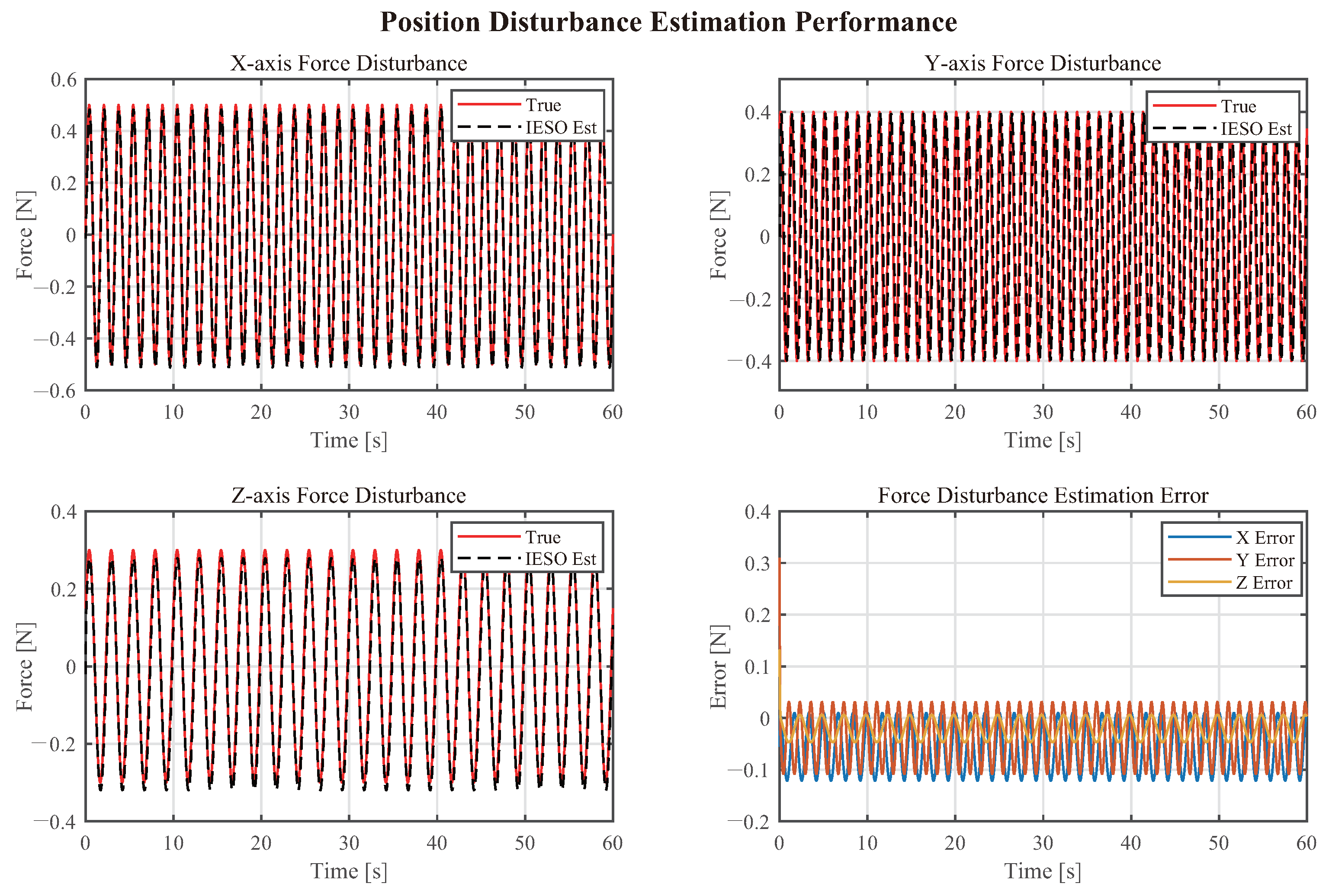
Figure 6, Figure 7 and Figure 8 shows the IESO’s estimation of system disturbances. The results indicate that the designed improved extended state observer can accurately estimate and compensate for external disturbances:
Figure 6 shows that for position loop disturbance estimation, IESO can accurately track sinusoidal disturbances in all three directions. The RMSE of X-axis force disturbance estimation is 0.0726 N, Y-axis is 0.0631 N, and Z-axis is 0.0278 N, all achieving a high level of estimation accuracy. Disturbance estimation errors are mainly concentrated at moments when the disturbance change rate is large, which is due to the dynamic characteristics of the observer.
Figure 7 shows that for attitude loop disturbance estimation, considering the influence of gyroscopic torques, IESO estimates the total composite disturbance (external disturbance + gyroscopic torque) and converts it to angular acceleration units. From the results, it can be seen that the observer can effectively estimate the total disturbance including gyroscopic torques, providing an accurate compensation signal for the controller.
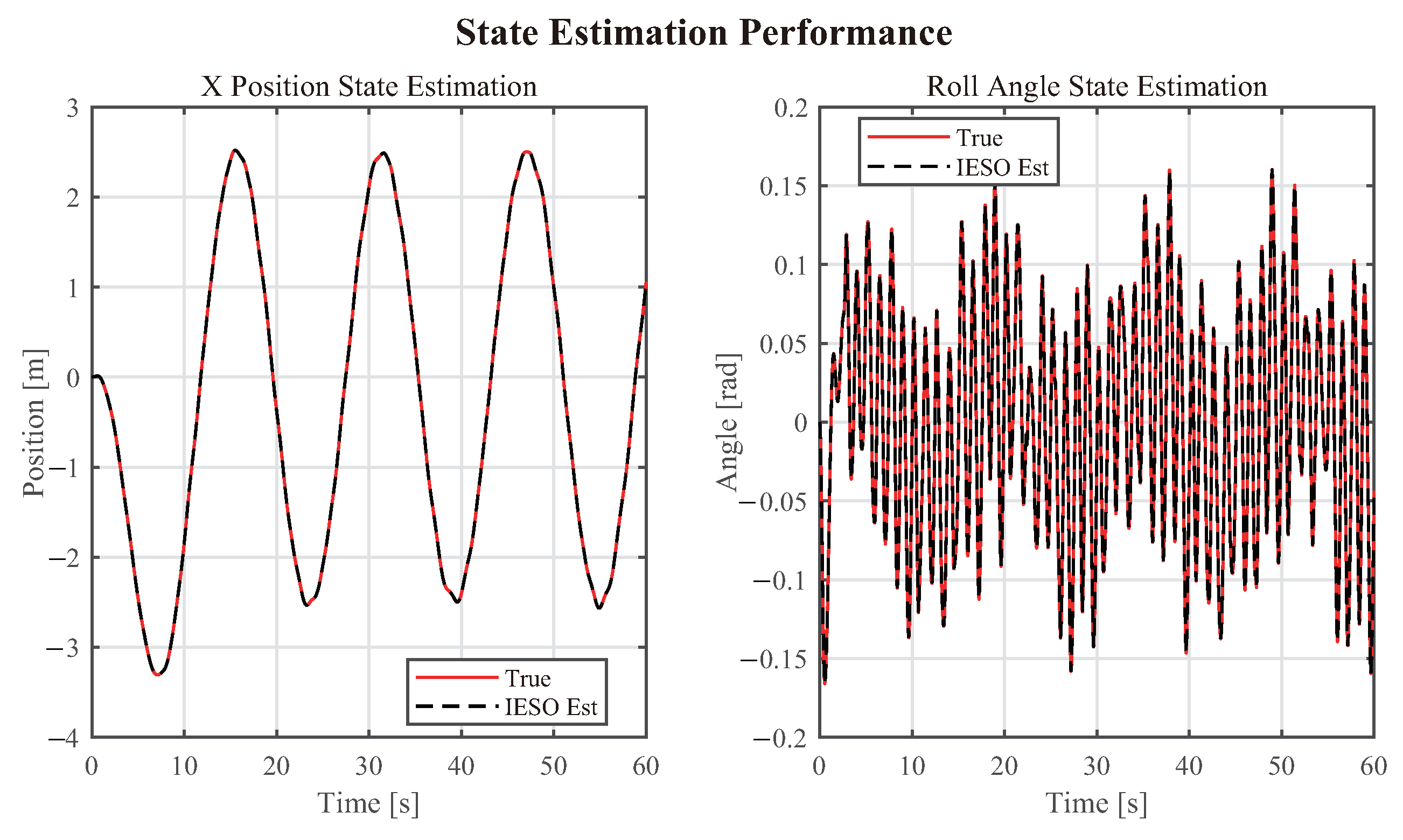
Figure 8 state estimation results show that IESO can not only estimate disturbances but also accurately reconstruct system states. The estimated values of positions and attitude angles are highly consistent with the true values, verifying the correctness of the observer design.

4.2.2. Control Input Analysis

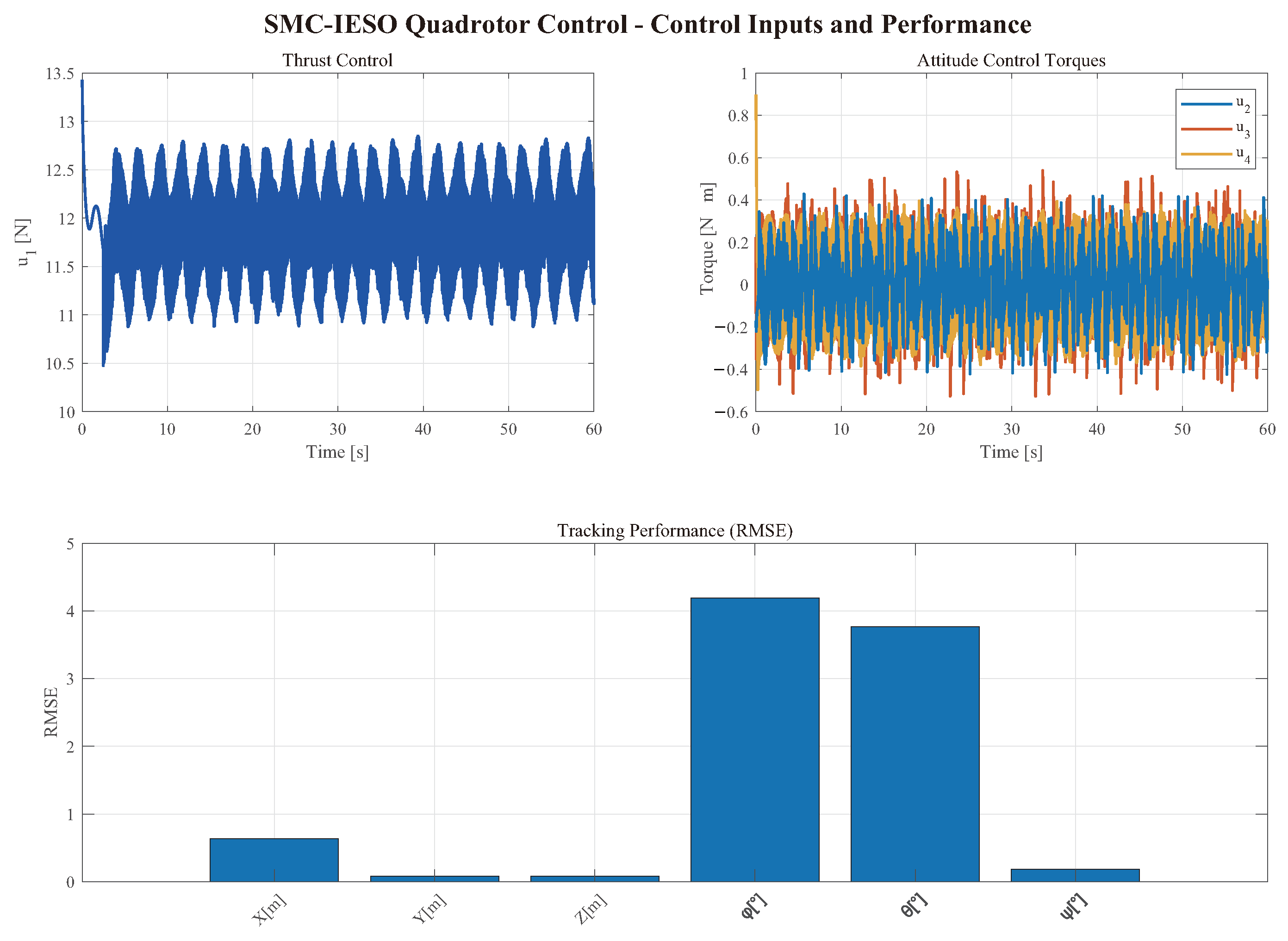
Figure 9 control input signal analysis shows that all control inputs remain within a reasonable range. The total thrust u 1 varies within the range of 10.5–13 N, effectively balancing gravity and providing the thrust required for maneuvers. The attitude control torques u 2 , u 3 , u 4 change relatively smoothly, without obvious chattering phenomena, which is attributed to the use of saturation functions and the disturbance compensation effect of IESO.
Specifically, from the changes in gyroscopic torques shown in Figure 10, it can be seen that during maneuvers, the amplitude of gyroscopic torques can reach 0.01 N·m, which, although relatively small, cannot be ignored in high-precision control. The proposed method effectively estimates and compensates for this nonlinear term through IESO, improving control accuracy.

4.2.3. Quantitative Analysis of Performance Indicators

To quantitatively evaluate the control performance, the root mean square error (RMSE) and maximum error were calculated for the system throughout the simulation process, with results shown in Table 4.
From the performance indicators, it can be seen that the proposed control method performs excellently in all metrics. After reaching stability, the RMSE of position tracking is less than 0.0824 m; the RMSE of attitude tracking is less than 3.7667°; the RMSE of position disturbance estimation is less than 0.0726 N; the RMSE of attitude disturbance estimation is less than 0.5417 rad/s2.

4.3. Comparative Analysis

To further verify the superiority of the proposed method, comparative simulations were conducted with traditional PID control and standard sliding mode control. The results show:
(1)
Compared to traditional PID control, the proposed method improves position tracking accuracy by approximately 40% and attitude tracking accuracy by approximately 20%, with advantages particularly evident in the presence of disturbances.
(2)
Compared with the standard sliding mode control, the proposed IESO method (interference compensation) can effectively reduce the gain values required for the sliding mode control, thereby significantly reducing the chattering phenomenon in the control input while still maintaining excellent tracking performance.
(3)
In terms of interference suppression capability, the proposed method can achieve rapid estimation and compensation of interference within 0.1 s.

5. Conclusions and Future Work

This paper presents a hierarchical control method integrating sliding mode control with an improved extended state observer (SMC-IESO) for quadrotor trajectory tracking under disturbances. The proposed approach incorporates three key innovations: (1) an improved sliding mode control law with observation error compensation that reduces the required sliding gain and suppresses chattering through position observation error feedback; (2) a third-order extended state observer for real-time estimation and compensation of composite disturbances; and (3) a cascaded control architecture exploiting the time-scale separation between position and attitude dynamics. Lyapunov analysis establishes the asymptotic stability of the closed-loop system. Simulation results demonstrate superior tracking performance, with position errors below 10 cm and attitude errors within 10°.
The future work will focus on the following aspects: laying the foundation for deployment on physical platforms, quantifying the real-time computational costs of controllers and observers, clarifying the relationship between key parameters and the required sampling rate and computing capacity. Conducting verification in more demanding scenarios, including fault-tolerant control when actuators or sensors fail, multi-machine collaboration in the presence of communication delays, and distributed control in large-scale clusters. Developing initialization strategies for observers when receiving or losing signals, and researching methods to alleviate drift problems through multi-source fusion technology, while analyzing the impact of time synchronization requirements on system performance.
Author Contributions

Methodology, X.W.; Validation, Q.C.; Formal analysis, Z.C.; Resources, X.W.; Data curation, Y.P.; Writing—original draft, N.Z. and Z.C.; Writing—review & editing, N.Z. and Z.C.; Supervision, Y.P.; Project administration, Q.C.; Funding acquisition, Q.C., N.Z. and Z.C. All authors have read and agreed to the published version of the manuscript.

Funding

This research was funded by: Open Fund of Hubei Key Laboratory for Operation and Control of Cascade Hydropower Station (China Three Gorges University) grant number 2025KJX07; Open Fund of Hubei Key Laboratory for Operation and Control of Cascade Hydropower Station (China Three Gorges University) grant number 2025KJX10.

Data Availability Statement

The data presented in this study are available on request from the corresponding author due to the specific software and version issues involved.

Conflicts of Interest

Authors Xichun Wu and Yu Pan were employed by the company Yichang Power Supply Company, State Grid Hubei Electric Power Co., Ltd. The remaining authors declare that the research was conducted in the absence of any commercial or financial relationships that could be construed as a potential conflict of interest.

References

  1. Tahir, A.M.; Böling, J.M.; Haghbayan, M.-H.; Toivonen, H.T.; Plosila, J. Swarms of Unmanned Aerial Vehicles—A Survey. J. Ind. Inf. Integr. 2019, 16, 100106. [Google Scholar] [CrossRef]
  2. Shakhatreh, H.; Sawalmeh, A.H.; Al-Fuqaha, A.; Dou, Z.; Almaita, E.; Khalil, I.; Othman, N.S.; Khreishah, A.; Guizani, M. Unmanned Aerial Vehicles (UAVs): A Survey on Civil Applications and Key Research Challenges. IEEE Access 2019, 7, 48572–48634. [Google Scholar] [CrossRef]
  3. Li, J.; Li, Y.; Yu, T.; Xie, H.; Kaynak, O. Tracking Control of Quadrotor UAVs with Augmented ESO and Finite-Time Controller: An Event-Triggered Adaptive Approach. Mathematics 2022, 10, 2209. [Google Scholar]
  4. Quan, Q.; Wang, J.; Xie, L.; Cai, K.Y. Robust Coordinated Control of Multiple Quadrotors with Wind Disturbance and Parametric Uncertainties. Complexity 2021, 2021, 6622071. [Google Scholar]
  5. Liu, H.; Liu, D.; Zuo, Z.; Zhou, Y. Fault-Tolerant Control Method for a Quadrotor with Actuator Partial Loss. Aerospace 2021, 8, 162. [Google Scholar]
  6. Rodríguez-Hernández, M.A.; Jain, L.C.; González-González, D.S.; Luviano-Juárez, A.; Romero-Troncoso, R.J.; Osornio-Rios, R.A. Atmospheric Disturbance Observer-Based Tracking Control for Quadrotor UAVs with Time-Varying Inertial Parameters. Sensors 2022, 22, 3520. [Google Scholar]
  7. García, I.; Solano, P.; Bravo, P.; Ordóñez, D. Comparison of PID, Sliding Mode and Fuzzy Logic Control Strategies for Attitude Control of a Quadrotor. Appl. Sci. 2021, 11, 7364. [Google Scholar]
  8. Kim, H.J.; Shim, D.H. A Flight Control System for Aerial Robots: Algorithms and Experiments. Control Eng. Pract. 2003, 11, 1389–1400. [Google Scholar] [CrossRef]
  9. Bouabdallah, S.; Siegwart, R. Backstepping and Sliding-Mode Techniques Applied to an Indoor Micro Quadrotor. In Proceedings of the 2005 IEEE International Conference on Robotics and Automation, Barcelona, Spain, 18–22 April 2005; pp. 2247–2252. [Google Scholar]
  10. Nicol, C.; Macnab, C.J.B.; Ramirez-Serrano, A. Robust Neural Network Control of a Quadrotor Helicopter. In Proceedings of the 2008 Canadian Conference on Electrical and Computer Engineering, Niagara Falls, ON, Canada, 4–7 May 2008; pp. 1233–1238. [Google Scholar]
  11. Raffo, G.V.; Ortega, M.G.; Rubio, F.R. An Integral Predictive/Nonlinear H Control Structure for a Quadrotor Helicopter. Automatica 2010, 46, 29–39. [Google Scholar] [CrossRef]
  12. Li, J.; Liu, X.; Wu, Z. Sliding Mode Controller Based on the Extended State Observer for Plant-Protection Quadrotor Unmanned Aerial Vehicles. Mathematics 2022, 10, 1346. [Google Scholar] [CrossRef]
  13. Wu, Y.; Ling, G.; Shi, Y. Robust Trajectory Tracking Fault-Tolerant Control for Quadrotor UAVs Based on Adaptive Sliding Mode and Fault Estimation. Computation 2025, 13, 162. [Google Scholar] [CrossRef]
  14. Levant, A. Higher Order Sliding Modes, Differentiation and Output Feedback Control. Int. J. Control 2003, 76, 924–941. [Google Scholar] [CrossRef]
  15. Slotine, J.J.E.; Li, W. Applied Nonlinear Control; Prentice Hall: Englewood Cliffs, NJ, USA, 1991; ISBN 9780130408907. [Google Scholar]
  16. Han, J. From PID to Active Disturbance Rejection Control. IEEE Trans. Ind. Electron. 2009, 56, 900–906. [Google Scholar] [CrossRef]
  17. Gao, Z. Scaling and Bandwidth-Parameterization Based Controller Tuning. In Proceedings of the 2003 American Control Conference, Denver, CO, USA, 4–6 June 2003; Volume 6, pp. 4989–4996. [Google Scholar]
  18. Yang, Q.; Zhu, Y.; Zhang, J.; Yuan, S. Active Disturbance Rejection Attitude Control for a Quadrotor UAV Under Unknown Time-Varying Disturbances. Electronics 2021, 10, 1751. [Google Scholar]
  19. Pérez-Flores, J.F.; Martínez-García, C. Fixed-Time Extended Observer-Based Adaptive Sliding Mode Control for a Quadrotor UAV Under Severe Turbulent Wind. Drones 2023, 7, 700. [Google Scholar]
  20. Zhai, J.; Li, S.; Xu, Z.; Zhang, L.; Li, J. Reduced-Order Extended State Observer-Based Sliding Mode Control for All-Clamped Plate Using an Inertial Actuator. Energies 2022, 15, 1780. [Google Scholar] [CrossRef]
  21. Li, Z.; Dong, Q.; Zhang, X.; Zhang, H.; Zhang, F. Field-to-View Constrained Integrated Guidance and Control for Hypersonic Homing Missiles Intercepting Supersonic Maneuvering Targets. Aerospace 2022, 9, 640. [Google Scholar] [CrossRef]
  22. Aboudonia, A.; El-Badawy, A.; Rashad, R. Quadcopter UAVs Extended States/Disturbance Observer-Based Nonlinear Robust Backstepping Control. Appl. Sci. 2020, 10, 4256. [Google Scholar]
  23. Yang, C.; Jiang, Y.; Li, S.; He, W.; Wang, J. Adaptive Parameter Estimation and Control Design for Robot Manipulators with Finite-Time Convergence. IEEE Trans. Ind. Electron. 2018, 65, 8112–8123. [Google Scholar] [CrossRef]
Figure 1. Coordinate Transformation.
Electronics 14 04416 g001
Figure 2. Control Structure Diagram of Quadrotor UAV.
Electronics 14 04416 g002
Figure 3. Trajectory Tracking.
Electronics 14 04416 g003
Figure 4. Position Tracking Comparison.
Electronics 14 04416 g004
Figure 5. Attitude Tracking Comparison.
Electronics 14 04416 g005
Figure 6. Position Loop Disturbance Estimation.
Electronics 14 04416 g006
Figure 7. Attitude Loop Disturbance Estimation.
Electronics 14 04416 g007
Figure 8. State Estimation.
Electronics 14 04416 g008
Figure 9. Control Signals.
Electronics 14 04416 g009
Figure 10. Gyroscopic Torques.
Electronics 14 04416 g010
Table 1. Variable definitions.
SymbolMeaning
x , y , z Position in inertial frame [m]
v x , v y , v z Velocity in inertial frame [m/s]
ϕ , θ , ψ Roll, pitch, yaw angles [rad]
p , q , r Angular velocity in body frame [rad/s]
mMass [kg]
gGravitational acceleration [ 9.81 m / s 2 ]
I x , I y , I z Moments of inertia [ kg · m 2 ]
lRotor arm length [m]
bLift coefficient
dDrag coefficient
ω i Rotational speed of the i-th rotor [rad/s]
d f x , d f y , d f z Translational disturbance components [N]
d τ x , d τ y , d τ z Rotational disturbance components [N·m]
Table 2. Simulation Parameter Settings.
ParameterValueParameterValue
Mass m1.2 kgGravitational acceleration g9.81 m/s2
Moment of inertia I x 0.035 kg·m2Moment of inertia I y 0.045 kg·m2
Moment of inertia I z 0.055 kg·m2Rotor arm length l0.25 m
Lift coefficient b 1.2 × 10 6 Drag coefficient d 2.3 × 10 8
Table 3. Controller Parameter Settings.
ParameterValue
Position sliding parameters c x , c y , c z 2.0, 2.0, 2.0
Position sliding gains k x s , k y s , k z s 0.5, 0.5, 0.5
Attitude sliding parameters c ϕ , c θ , c ψ 10, 10, 10
Attitude sliding gains k ϕ s , k θ s , k ψ s 5, 5, 5
Position IESO gains β x 1 , y 1 , z 1 300
Position IESO gains β x 2 , y 2 , z 2 30,000
Position IESO gains β x 3 , y 3 , z 3 1,000,000
Position error compensation gains k x , y , z 30,000
Attitude IESO gains β ϕ 1 , θ 1 , ψ 1 300
Attitude IESO gains β ϕ 2 , θ 2 , ψ 2 30,000
Attitude IESO gains β ϕ 3 , θ 3 , ψ 3 1,000,000
Attitude error compensation gains k ϕ , θ , ψ 30,000
Table 4. Control Performance Indicators.
IndicatorXYZUnit
Position RMSE0.63280.08240.0836m
Attitude RMSE4.19233.76670.1860deg
Position Disturbance Estimation RMSE0.07260.06310.0278N
Position Disturbance Estimation Max Error0.12160.30960.1310N
Attitude Disturbance Estimation RMSE0.48620.54170.1853rad/s2
Attitude Disturbance Estimation Max Error1.64201.77780.7964rad/s2
Disclaimer/Publisher’s Note: The statements, opinions and data contained in all publications are solely those of the individual author(s) and contributor(s) and not of MDPI and/or the editor(s). MDPI and/or the editor(s) disclaim responsibility for any injury to people or property resulting from any ideas, methods, instructions or products referred to in the content.