Article

Rapid Thermal Annealing for Reduced Leakage and Enhanced Endurance of Reactive-Sputtered AlScN-Based Ferroelectric Memory Capacitors

1
School of Electronic Engineering, Soongsil University, Seoul 06938, Republic of Korea
2
Department of Intelligent Semiconductor, Soongsil University, Seoul 06938, Republic of Korea
*
Author to whom correspondence should be addressed.
Electronics 2025, 14(21), 4353; https://doi.org/10.3390/electronics14214353
Submission received: 11 September 2025 / Revised: 2 November 2025 / Accepted: 4 November 2025 / Published: 6 November 2025

Abstract

In this study, we investigate the effects of rapid thermal annealing (RTA) in a nitrogen ambient on Al0.8Sc0.2N metal–ferroelectric–metal capacitors. The RTA treatment of up to 13 min on an as-deposited AlScN film markedly improves electrical reliability while maintaining remanent polarization largely unchanged. The leakage current density decreases from 152.63 to 71.37 mA/cm2, and endurance increases to 5000 cycles. X-ray diffraction analysis reveals enhanced crystalline and improved c-axis orientation, which mitigates grain-boundary defects and suppresses leakage pathways. The RTA promotes Pt diffusion, resulting in an 11% increase in the dielectric constant. Moreover, it introduces tensile strain that reduces the coercive field by lowering the ferroelectric switching barrier. These findings indicate that the RTA process in a nitrogen atmosphere is an effective approach for improving the quality of AlScN thin film, thereby supporting the development of its reliable ferroelectric devices.

1. Introduction

Aluminum-scandium nitride (AlScN) has been established as a highly promising ferroelectric material for next-generation memory and logic devices, primarily owing to its robust polarization and full compatibility with standard CMOS fabrication flows [1,2,3]. The incorporation of Sc into the wurtzite AlN lattice induces a non-centrosymmetric phase, giving rise to a strong spontaneous polarization that is reversibly switchable [4]. This property allows AlScN thin films to exhibit a large remanent polarization often exceeding 100 μC/cm2, as well as a high coercive field, which are critical performance metrics for non-volatile applications such as ferroelectric random-access memories and ferroelectric field-effect transistors [5,6]. Furthermore, its excellent thermal stability of a high Curie temperature (~1100 °C), along with the availability of scalable deposition techniques such as RF magnetron sputtering and metal–organic chemical vapor deposition, makes it highly suitable for practical applications [7,8,9].
The immense potential of sputtered AlScN films is deterred by the challenges in their structural and electrical quality. The ferroelectric properties of AlScN are sensitive to film quality, which is particularly difficult to control during the sputtering process [10,11]. Minor deviations in deposition parameters such as gas pressure, power, and temperature can lead to severe microstructural defects, including poor crystallinity, competing polar orientations, and the formation of non-ferroelectric rock salt phases [12,13]. These structural imperfections act as charge trapping sites and leakage pathways, resulting in high leakage currents and rapid degradation of ferroelectric switching endurance [14,15]. Such electrical deficiencies undermine the non-volatility and long-term reliability of AlScN-based devices, presenting a major bottleneck for their practical implementation.
To address these issues, various post-deposition treatments have been reported to improve the quality of AlScN films. Among these, thermal annealing has proven to be a particularly effective strategy for enhancing crystalline structure and mitigating defects. Annealing can facilitate grain growth, reduce internal strain, and mitigate point defects, which result in a significant reduction in leakage current and an improvement in ferroelectric stability [16,17,18]. Still, the optimization of annealing parameters remains an active area of research. The choice of technique, including RTA, along with specific conditions like ambient atmosphere and duration, can have a profound impact on the resulting structure-property relationships.
This study aims to systematically investigate the effects of rapid thermal annealing in a nitrogen (N2) ambience on the properties of sputtered Al0.8Sc0.2N thin films. The as-deposited films were subjected to RTA for different durations (3 and 13 min), and each AlScN based metal–ferroelectric–metal (MFM) capacitor was fabricated. The objective of this study is to investigate the impact of rapid thermal annealing (RTA) compared to the reported conventional furnace annealing [19]. We set the RTA time with a 10 min interval (3 min and 13 min) for comparison. A comprehensive analysis was then performed to correlate the changes in structural characteristics, which were evaluated via atomic force microscopy (AFM) and X-ray diffraction (XRD), with the resulting electrical performance. X-ray photoelectron spectroscopy (XPS) measurements were additionally conducted to investigate variations in chemical composition. The ferroelectric switching, leakage current, endurance, and dielectric properties were thoroughly characterized to establish a clear relationship, providing insights for the optimization of AlScN for high performance device applications.

2. Materials and Methods

MFM capacitors were fabricated on a p-type Si substrate. The process began with the deposition of a Ti/Pt (5 nm/50 nm) bottom electrode via sequential sputtering. Subsequently, a 50 nm thick Al0.8Sc0.2N ferroelectric film was deposited using an RF magnetron sputtering system equipped with an Al0.57Sc0.43 alloy target. The deposition was performed at a chamber pressure of 5 mTorr using a gas mixture of Ar (15 sccm) and N2 (30 sccm). A set temperature of a substrate stage and applied power were maintained at 400 °C and 280 W, respectively. Following deposition, the samples were classified into three groups: an as-deposited sample (without annealing), and two samples that underwent additional RTA at 400 °C in a flowing N2 atmosphere (30 sccm) for 3 min or 13 min. Finally, Ni top electrodes (50 nm thickness, 40 µm diameter) were patterned using a lift-off process after sputter deposition to complete the MFM structure. A cross-sectional schematic of the final MFM structure is shown in Figure 1a. For each device condition (as-deposited, RTA 3 min, and RTA 13 min), about ten devices were fabricated and characterized. The results from representative devices are presented and discussed. It is to be noted that statistical distributions of devices are summarized in the last part.
The structural and morphological characteristics of the fabricated devices were analyzed using AFM (NX-10, Park Systems, Suwon, Republic of Korea) over a scan area of 1 × 1 µm2. The crystalline structure was evaluated using XRD analysis (D8-Advance α1 system, Bruker, Billerica, MA, USA) over a 2θ scan range of 20–80°. The XRD measurements in this study were performed using a Cu Kα1 radiation source (λ = 1.54056 Å) as the monochromatic wavelength. The elemental composition and chemical states of Sc, N, O, and Al as a function of film depth were analyzed by XPS (K-alpha+, Thermo Fisher Scientific, Waltham, MA, USA). Electrical properties were measured using a Keithley 4200A-SCS (Tektronix, Beaverton, OR, USA) semiconductor parameter analyzer combined with a PMU-4225 (Tektronix, Beaverton, OR, USA) pulse measurement unit. To evaluate device performance, polarization–electric field (P–E) hysteresis loops and retention tests were conducted. Specifically, to minimize the influence of leakage current on the remanent polarization evaluation, positive-up negative-down (PUND) measurements were performed at a frequency of 10 kHz.

3. Results

Figure 1b shows representative AFM topography images of each surface morphology. The as-deposited AlScN film exhibited a smooth surface with a root-mean-square (RMS) roughness of 0.485 nm. It is nearly identical to that of the underlying Pt bottom electrode (0.486 nm), indicating that the film growth was highly smooth. Upon annealing, a slight increase in surface roughness was observed, which is consistent with thermally driven grain growth. The RMS roughness increased to 0.569 nm after 3 min RTA and further to 0.587 nm after 13 min RTA. The negligible difference between the two annealed samples strongly indicates that the initial 3 min thermal annealing is a crucial step, accounting for the majority of morphological changes. Extended annealing, by contrast, has only an insignificant additional impact on the surface roughness. It has been reported that crystallinity can be improved even when the surface roughness shows little or no change [16].
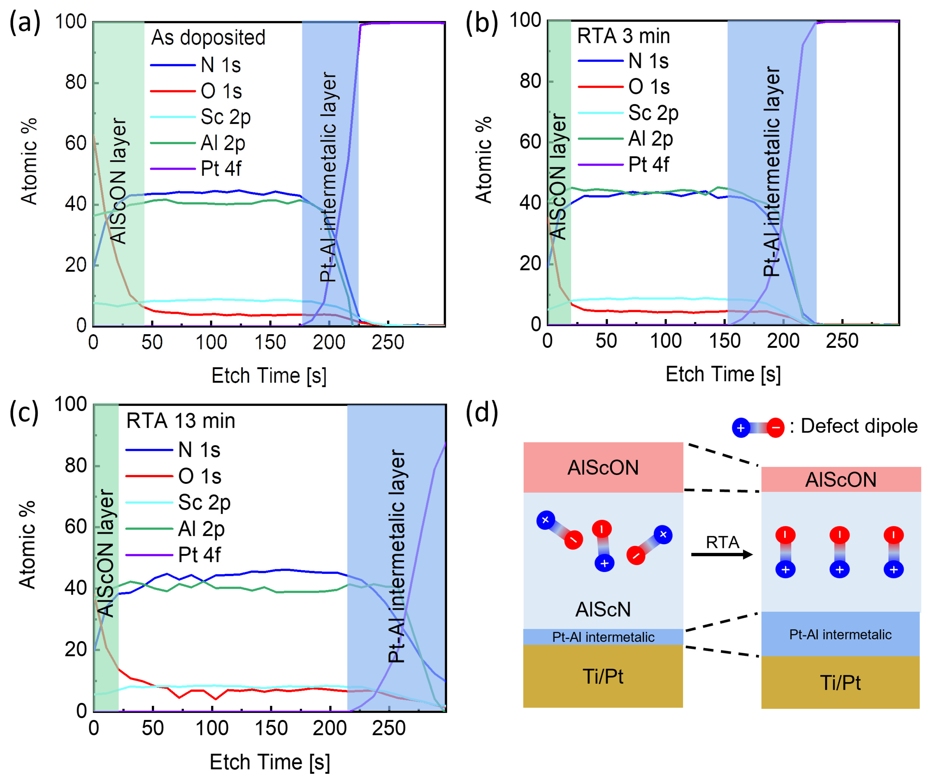
The crystallinity of the as-deposited and annealed AlScN films was analyzed by XRD analysis. Figure 1c presents the resulting 2θ scan patterns. All samples display a prominent diffraction peak corresponding to the AlScN (0002) plane, confirming the formation of a c-axis oriented wurtzite crystal structure [19]. The annealing process induced two observable changes in the (0002) peak as presented in the magnified plots in Figure 1d. Figure 1e presents the overall XRD pattern. First, the peak position progressively shifted to higher diffraction angles from 35.60° (the as-deposited film) to 35.66° (3 min RTA) and 35.74° (13 min RTA). This shift corresponds to a reduction in the c-axis lattice constant, indicating enhancement of in-plane tensile strain within the film arising from the lattice mismatch with the bottom Pt electrode [19,20]. Second, the peak intensity increased with the longer annealing times, which rose from 445 a.u. (as deposited) to 770 a.u. (3 min) and 994 a.u. (13 min). This enhancement is attributed to a combination of grain growth and improved c-axis orientation, which reduces the density of grain boundaries and associated defects [21,22]. A minor shift in the Pt peaks was also observed, which is likely attributed to the inherent lattice mismatch and coefficient of thermal expansion (CTE) mismatch between the electrode stack and Si substrate. The shift in the Pt(111) diffraction peak was more pronounced than that of the AlScN peak, which can be attributed to the difference in strain between the Pt–AlScN and Pt–Si interfaces [23]. However, further complete structural analysis, including rocking curve FWHM analysis, is suggested to fully confirm the crystallinity improvement. To investigate the chemical changes induced by the RTA process, XPS analysis was performed on the as-deposited and two annealed AlScN films. As presented in Figure 2a–c, the surface atomic composition analysis reveals a clear trend: the nitrogen signal intensity increases while the oxygen signal decreases. Specifically, the O1s atomic concentration drops by 41.13% and 39.61% for the 3 min and 13 min annealed samples, respectively. This trend is attributed to the thermal decomposition of unstable AlOXNY bonds on the surface of the as-deposited film. During high-temperature annealing in an N2 atmosphere, these bonds are broken down and are replaced by more thermodynamically stable Al–N bonds [24]. Consequently, the N1s signal intensifies, while the O 1s signal diminishes due to the removal of oxygen-related species. This compositional shift indicates effective surface modification and thus enhanced nitridation of the AlScN film during the RTA process. The XPS analysis also suggests that the longer 13 min RTA at 400 °C promotes interdiffusion at the AlScN/Pt interface [25,26]. The portion of Al appears to react with the underlying platinum to form a Pt2Al3 intermetallic layer, which lowers the absolute Al atomic fraction detected by XPS [27]. The formation of this intermetallic layer introduces a measurement artifact during depth profiling. Due to its higher mass density and Pt-rich composition, the Pt2Al3 layer exhibits a lower sputter yield when etched with Ar+ ions [28]. This artificially slows the etch rate near the interface. As a result, the standard time-to-depth profiling overestimates the film thickness in this region, making the AlScN layer appear thicker in the XPS profile than it is physically. Intermetallic-induced variations in sputtering efficiency have been reported to cause apparent shifts in interface positions and broadening of elemental distributions, even when the physical thickness remains constant [29,30]. The difference in Pt signal onset is therefore considered to result from a sputtering-yield artifact associated with Pt2Al3 formation during RTA. These chemical transformations at the surface and interface are illustrated in the schematic of Figure 2d. Comprehensively, the RTA process induced structural reordering and an increase in the c-axis lattice constant, which consequently enhanced the in-plane tensile stress. In addition, the reduction in residual defects and oxygen-related bonds within the AlScN thin film during RTA improved the overall crystallinity, resulting in an increased c-axis lattice constant that can be interpreted as a relative increase in-plane tensile strain. Furthermore, due to the mismatch in the CTE between the Pt electrode and the AlScN film, Pt (≈8.8 × 10⁻⁶ K−1) contracted more than AlScN (≈4.5 × 10⁻⁶ K−1) during the cooling process, thereby introducing additional in-plane tensile stress within the AlScN layer. These combined stress effects are considered to be responsible for the observed changes in the c-axis lattice parameter and the corresponding Bragg peak shift after annealing [16,31].
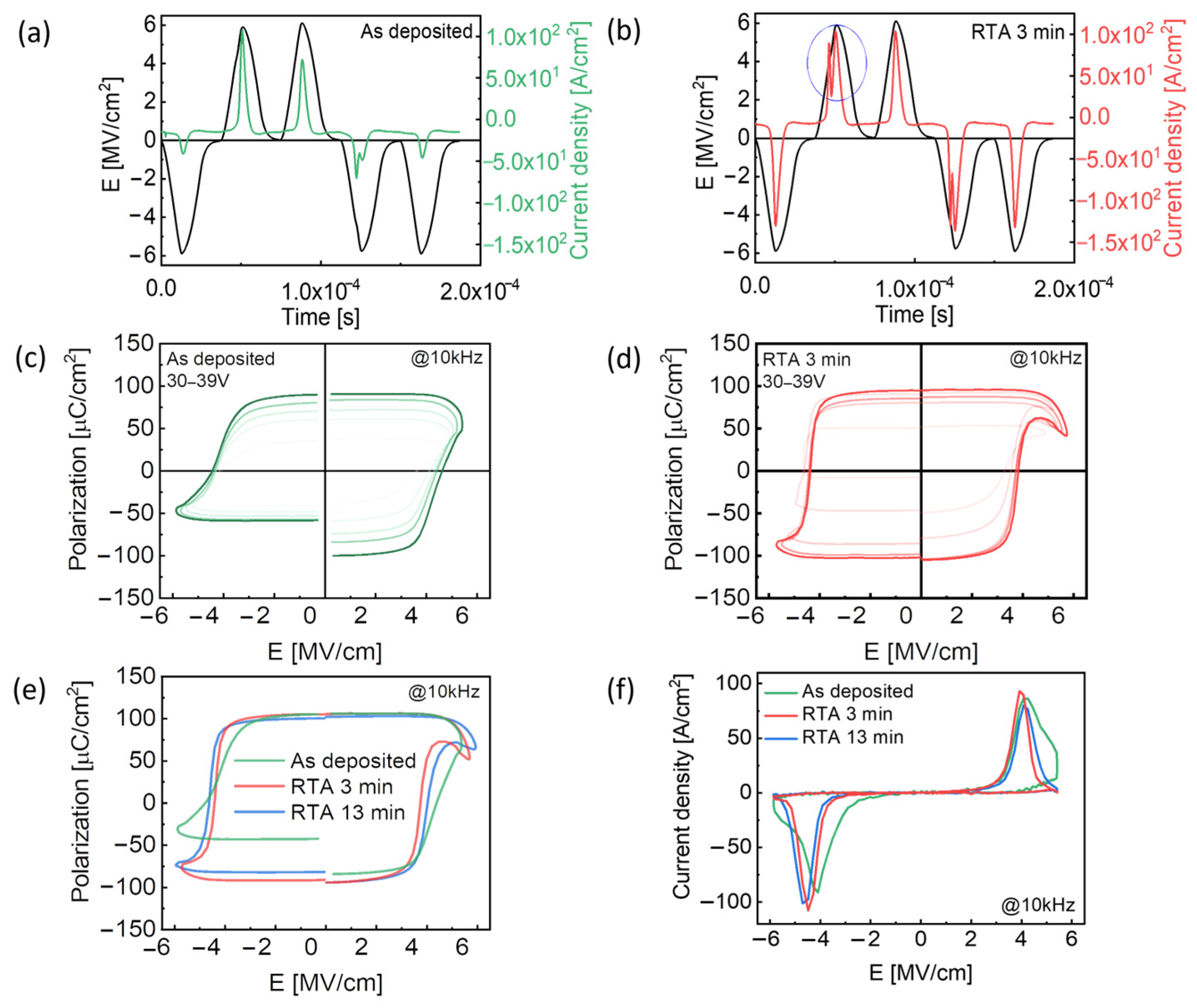
In addition to the structural and chemical analysis, the ferroelectric properties of the AlScN films were evaluated by performing PUND measurements on fabricated MFM capacitors. Figure 3a,b present switching current characteristics for the as-deposited state and 3 min RTA device. In Figure 3b, a peak splitting of measured current was affected by measurement noise. Figure 3c,d show the P-E loops measured for the input voltage range of 30 V to 39 V. The observed peak current splitting in the switching current affected the shape of the P-E loops. Figure 3e compares the measured P-E loops for each device under the applied voltage of 39 V at 10 kHz. Figure 3f presents their corresponding switching current densities. A comparison of these results reveals that the RTA process did not result in a measurable change in remanent polarization. However, it is to be noted that a progressive decrease in the coercive field (Ec) was observed with longer annealing times. The Ec value decreased from 4.42 MV/cm to 4.08 MV/cm and 3.91 MV/cm for the 3 min and 13 min RTA samples, respectively. This reduction is attributed to the tensile strain induced during the RTA process, which contracts the c-axis lattice constant and lowers the ferroelectric switching barrier [19,32]. In addition, the stabilization of the chemical composition, confirmed by XPS through the reduction of oxygen-related bonds and the formation of more stable Al–N bonds, also contributed to the decrease in the coercive field and the suppression of leakage current [33]. Furthermore, the RTA process enhances the loop’s symmetry by reconfiguring charged defect dipoles within the AlScN layer. This effect weakens the internal field (i.e., imprint), thereby reducing the horizontal offset of the P-E loop and improving its symmetry [23].
Figure 4a presents capacitance-voltage (C-V) measurement results used to extract the dielectric constant (εr) of the films. RTA resulted in an approximate 11% increase in the dielectric constant from 24.22 of the as-deposited to 26.9 for both annealed samples, as shown in Figure 4b. This enhancement is attributed to Pt diffusion into the AlScN film during the RTA [25,26]. This thermally assisted intermixing reduces the effective dielectric thickness and thus results in a higher measured capacitance and dielectric constant [25]. Consistent with the reduction in the internal field as observed in the P-E loops, the center of the C-V “butterfly” curve also exhibits a rightward shift along the electric field axis after the annealing [23,34]. The impact of RTA on leakage current density is shown in Figure 4c (log scale) and Figure 4d (linear scale). Asymmetric current behavior was observed between negative and positive electric fields, which can be attributed to the difference in work function and interfacial reactivity between the top and bottom electrodes, leading to the formation of different barrier heights depending on the field polarity [35]. All annealed devices exhibited a significant reduction in leakage current. The effect was most pronounced in the 13 min annealed sample, where the leakage current density at 3 MV/cm was 71.37 mA/cm2. This represents a more than twofold reduction from the initial value of 152.63 mA/cm2 measured for the as-deposited device under the same bias condition. This improvement is a direct consequence of the enhanced crystalline quality achieved via RTA. The thermal treatment promotes the growth of well-aligned and c-axis-oriented grains, while converting or eliminating abnormally oriented ones. Therefore, the reduction in the density of grain boundaries, which are known to serve as primary leakage pathways, effectively suppresses the steady-state leakage current [16,19].
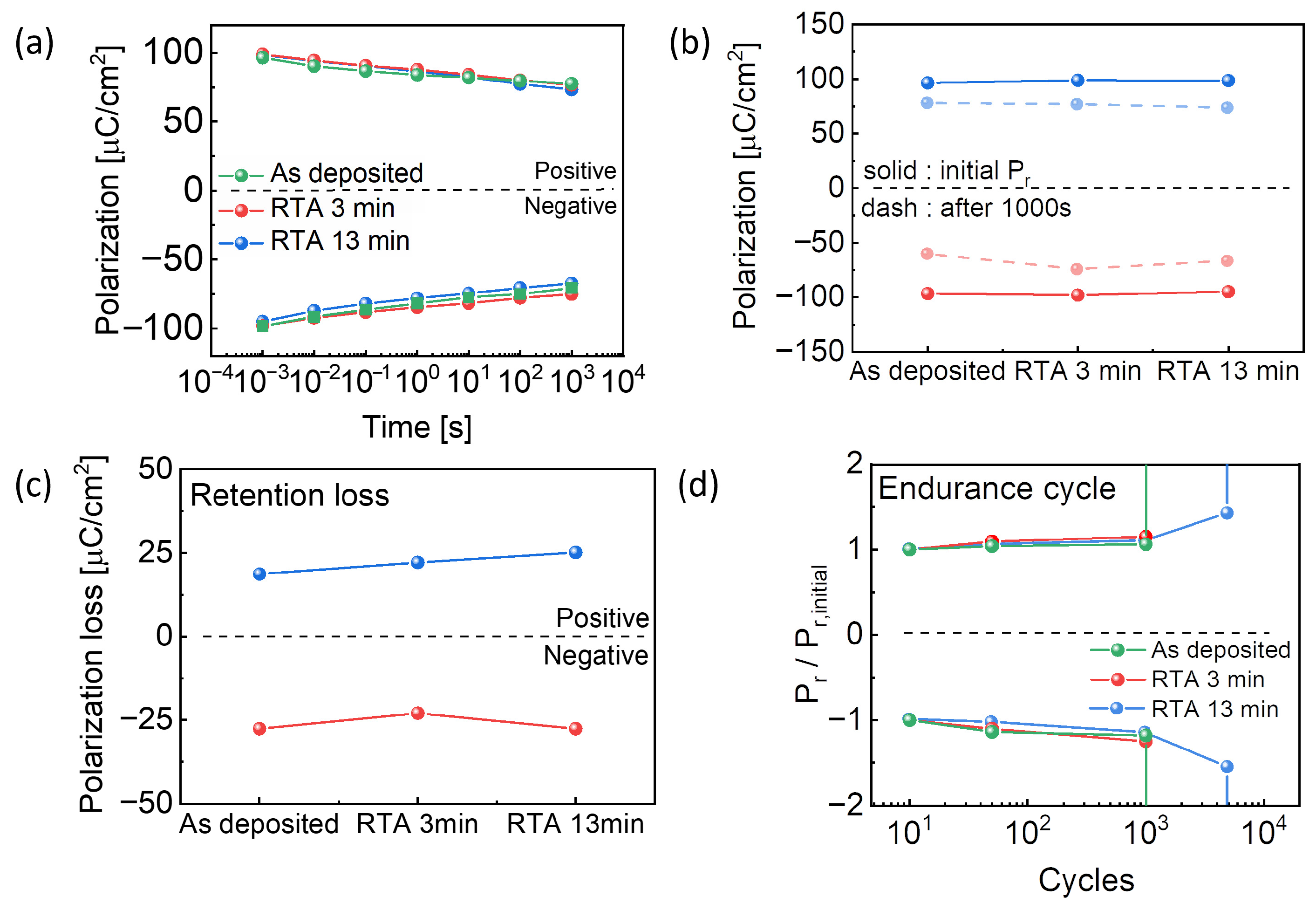
Retention characteristics of the fabricated MFM devices over time are presented in Figure 5. During an initial phase up to 1000 s, all three samples (i.e., as-deposited, 3 min, and 13 min RTA) exhibited nearly similar behaviors as in Figure 5a. The change in remanent polarization (Pr) after the test period was measured for both positive and negative states. During longer durations, as shown in Figure 5b,c, the degradation of Pr remained comparable between the three devices, with no clear relation between the annealing time and retention loss. For the positive retention state, the change in remanent polarization (ΔPr) was measured to be −18.67, −22.15, and −25.13 μC/cm2 for the as-deposited, 3 min, and 13 min annealed samples, respectively. For the negative retention state, the corresponding ΔPr values were 27.66, 22.99, and 27.64 μC/cm2. The results confirm that the RTA process in a nitrogen ambience has a negligible effect on long-term charge retention. The retention characteristics exhibited negligible change after the RTA process. This is because the polarization stability in wurtzite AlScN is primarily governed by the depolarization field, leakage-charge compensation, and strong domain pinning associated with its large coercive field. Therefore, a short-time RTA can effectively suppress defect-assisted degradation and reduce leakage current, but it does not significantly modify the intrinsic polarization retention mechanism [36]. As a result, no clear trend was observed in retention and polarization among the as-deposited, 3 min, and 13 min RTA samples, indicating that the short thermal budget mainly influences extrinsic reliability factors such as leakage and fatigue rather than altering the fundamental ferroelectric switching behavior. In contrast to the retention behavior, however, endurance characteristics were significantly improved after the RTA process. While the as-deposited and 3 min RTA devices maintained reliable polarization switching up to 1000 cycles, the 13 min RTA device maintained stable and consistent operation for over 5000 cycles. The endurance improvement is primarily attributed to the enhanced crystallinity and grain growth induced by the RTA process. During RTA, the localized thermal energy promotes recrystallization and grain coalescence, reducing the density of grain boundary defects that act as charge-trapping sites and leakage paths. This suppression of defect states mitigates local field concentration and charge accumulation, thereby alleviating fatigue during repeated polarization switching [37,38]. However, in the case of the 3 min RTA sample, the annealing duration appears insufficient to fully activate these microstructural improvements. The limited thermal budget likely resulted in partial grain growth and incomplete defect relaxation, leading to only modest endurance enhancement compared to the as-deposited film. In contrast, longer or more optimized RTA conditions are expected to further improve endurance by facilitating more extensive microstructural rearrangement and defect passivation. Although the retention remained nearly unchanged, the endurance performance improved significantly. However, the endurance (5000 cycles) and retention (~103 s) achieved in this study are still insufficient to meet the practical requirements for non-volatile memory applications (≥106 cycles and long-term retention).
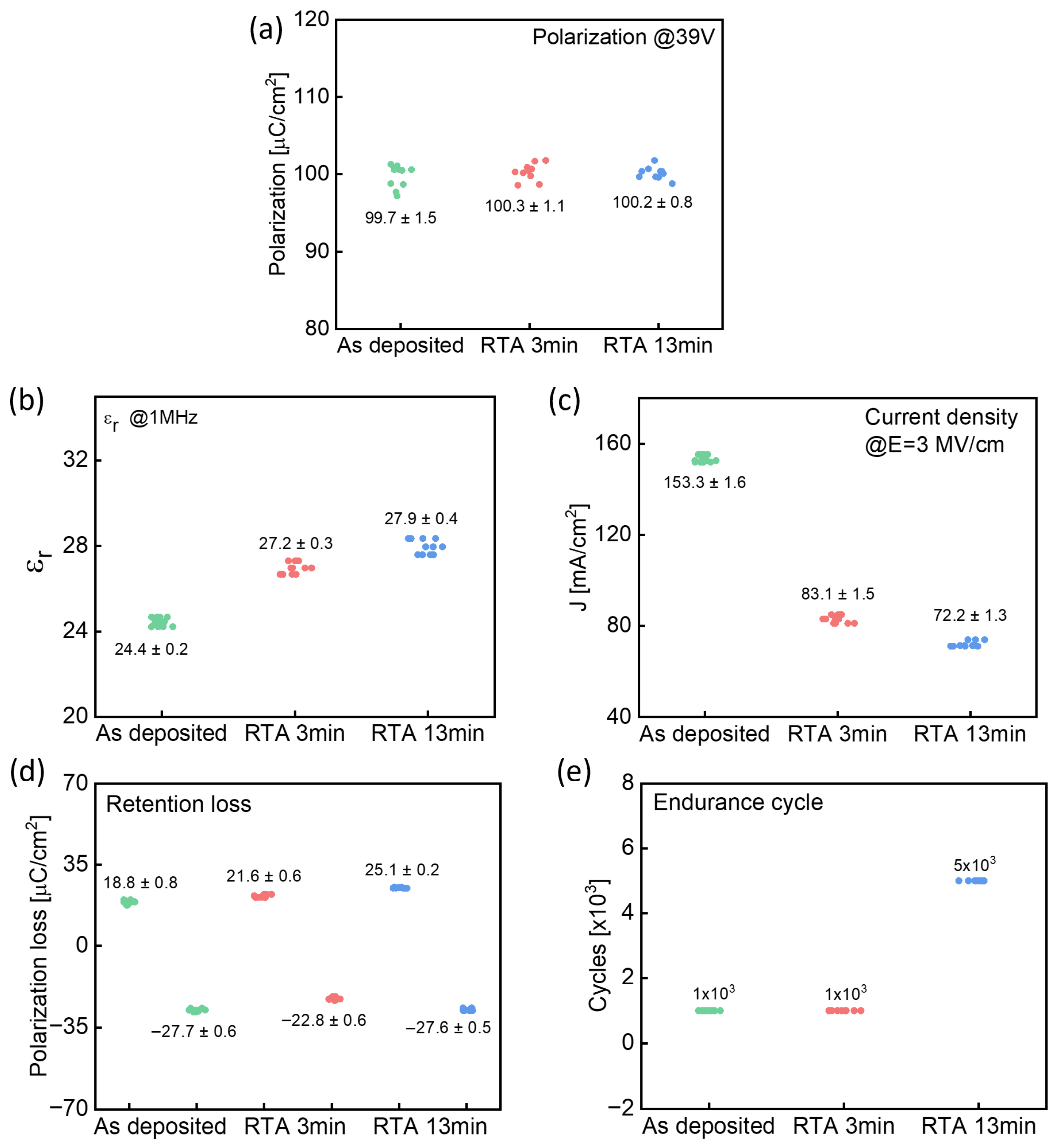
Figure 6 summarizes the statistical distribution of parameters from characterized devices using each measurement method (PUND, C–V, leakage current, retention, and endurance). In Figure 6a–d, twelve devices are characterized for each condition, showing consistent distributions and trends. The polarization characteristics exhibited a negligible variation among the three samples, while the dielectric constant showed an incremental change after the RTA process. Leakage current density decreased depending on the RTA time. Retention loss behavior remained nearly identical across all devices. It is to be noted that the number of devices for endurance is slightly different because of the exclusion of prematurely failed devices. Specifically, Figure 6e presents 12, 8, and 8 devices for the as-deposited, RTA 3 min, and RTA 13 min, respectively. Although the as-deposited and RTA 3 min samples exhibited comparable endurance characteristics, the RTA 13 min sample clearly exhibited up to 5000 cycling pulses without breakdown.
Therefore, this work is presented as a fundamental study that primarily demonstrates the beneficial effects of the RTA process on initial endurance improvement and leakage current suppression, rather than as direct evidence of memory applicability.

4. Conclusions

In this study, we demonstrated that post-deposition RTA in a nitrogen ambience is an effective method for enhancing the structural and electrical properties of reactive-sputtered ferroelectric AlScN film. The thermal treatment was found to improve the crystalline quality by promoting grain growth and improving c-axis orientation. At the same time, XPS analysis confirmed a surface modification effect, where unstable surface oxynitrides decomposed, leading to reduction in oxygen content and the formation of more stable Al-N bonds. These structural and chemical enhancements are directly correlated to improvements in electrical properties. The primary benefit of the improved crystallinity was a substantial reduction in leakage current by more than 50%, which in turn extended the device’s endurance fivefold from 1000 to 5000 cycles. While the remanent polarization was preserved, the RTA-induced tensile strain results in a beneficial reduction in the coercive field, facilitating easier polarization switching. A modest increase in the dielectric constant was also observed owing to Pt interdiffusion. Consequently, these findings highlight that the RTA process is effective in mitigating defects in the AlScN film. However, the RTA process contributes negligible improvement in retention and polarization. And thus both Pr value and retention characteristics exhibited minor changes, representing a limitation of the present study. These results indicate the importance of post-deposition treatment for fabricating more reliable and robust ferroelectric devices for next-generation electronic applications. Nevertheless, it is to be noted that there might be uncertainty in our conclusion because it is supported by limited structural analysis such as XPS as well as XRD results and literature study. Further complete and direct microstructural analysis is suggested for future work. A relatively high leakage current is still observed in comparison with state-of-the-art HfO2-based ferroelectric devices. Therefore, further suppression of leakage current through interfacial engineering and the incorporation of an oxide interlayer will remain an important direction for future research (Table 1).

Author Contributions

Conceptualization, J.B. and G.Y.; methodology, J.B., Y.L., J.M.P. and H.J.J.; fabrication, J.B. and Y.L.; investigation, J.B.; data curation, J.B.; writing—original draft preparation, J.B.; supervision, G.Y.; project administration, G.Y.; funding acquisition, G.Y. All authors have read and agreed to the published version of the manuscript.

Funding

This work was supported by the National Research Foundation grant (No. RS-2024-00455423) and Korea Evaluation Institute of Industrial Technology (KEIT) grant (No. RS-2024-00509266) funded by the Korea Governments (MSIT and MOTIE).

Data Availability Statement

The original contributions presented in this study are included in the article. Further inquiries can be directed to the corresponding authors.

Conflicts of Interest

The authors declare no conflicts of interest.

References

  1. Liu, Y.; Kuo, J.; Lal, A.; Sharma, J.; Singh, N. Characterization of Metal Effect on Solidly Mounted AlScN on CMOS. In Proceedings of the 2020 IEEE International Ultrasonics Symposium (IUS), Las Vegas, NV, USA, 7–11 September 2020. [Google Scholar] [CrossRef]
  2. Liu, X.; Wang, D.; Kim, K.-H.; Katti, K.; Zheng, J.; Musavigharavi, P.; Miao, J.; Stach, E.A.; Olsson, R.H., III; Jariwala, D. Post-CMOS Compatible Aluminum Scandium Nitride/2D Channel Ferroelectric Field-Effect-Transistor Memory. Nano Lett. 2021, 21, 3753–3761. [Google Scholar] [CrossRef]
  3. Kim, K.-H.; Oh, S.; Fiagbenu, M.M.A.; Zheng, J.; Musavigharavi, P.; Kumar, P.; Trainor, N.; Aljarb, A.; Wan, Y.; Kim, H.M.; et al. Scalable CMOS back-end-of-line-compatible AlScN/two-dimensional channel ferroelectric field-effect transistors. Nat. Nanotechnol. 2023, 18, 1044–1050. [Google Scholar] [CrossRef] [PubMed]
  4. Fichtner, S.; Wolff, N.; Lofink, F.; Kienle, L.; Wagner, B. AlScN: A III-V Semiconductor Based Ferroelectric. J. Appl. Phys. 2019, 125, 114103. [Google Scholar] [CrossRef]
  5. Oh, S.Y.; Kim, S.; Lee, G.; Park, J.-H.; Jeon, D.; Kim, S.; Yoo, G. Wide-Range Threshold Voltage Tunable β-Ga2O3 FETs with a Sputtered AlScN Ferroelectric Gate Dielectric. IEEE Electron Device Lett. 2024, 45, 1558–1561. [Google Scholar] [CrossRef]
  6. Chen, L.; Liu, C.; Li, M.; Song, W.; Wang, W.; Wang, Z.; Wang, N.; Zhu, Y. Scandium-Doped Aluminum Nitride for Acoustic Wave Resonators, Filters, and Ferroelectric Memory Applications. ACS Appl. Electron. Mater. 2023, 5, 612–622. [Google Scholar] [CrossRef]
  7. van Deurzen, L.; Nguyen, T.-S.; Casamento, J.; Xing, H.G.; Jena, D. Epitaxial Lattice-Matched AlScN/GaN Distributed Bragg Reflectors. Appl. Phys. Lett. 2023, 123, 241104. [Google Scholar] [CrossRef]
  8. Barth, S.; Bartzsch, H.; Gloess, D.; Frach, P.; Herzog, T.; Walter, S.; Heuer, H. Sputter Deposition of Stress-Controlled Piezoelectric AlN and AlScN Films for Ultrasonic and Energy Harvesting Applications. IEEE Trans. Ultrason. Ferroelectr. Freq. Control 2014, 61, 1329–1337. [Google Scholar] [CrossRef]
  9. Moe, C.G.; Leathersich, J.; Carlstrom, D.; Bi, F.; Kim, D.; Shealy, J.B. Metal–Organic Chemical Vapor Deposition-Grown AlScN for Microelectromechanical-Based Acoustic Filter Applications. Phys. Status Solidi A 2023, 220, 2200849. [Google Scholar] [CrossRef]
  10. Barth, S.; Schreiber, T.; Cornelius, S.; Zywitzki, O.; Modes, T.; Bartzsch, H. High Rate Deposition of Piezoelectric AlScN Films by Reactive Magnetron Sputtering from AlSc Alloy Targets on Large Area. Micromachines 2022, 13, 1561. [Google Scholar] [CrossRef]
  11. Lu, Y.; Reusch, M.; Kurz, N.; Ding, A.; Christoph, T.; Kirste, L.; Lebedev, V.; Žukauskaitė, A. Surface Morphology and Microstructure of Pulsed DC Magnetron Sputtered Piezoelectric AlN and AlScN Thin Films. Phys. Status Solidi A 2018, 215, 1700559. [Google Scholar] [CrossRef]
  12. Liu, H.Y.; Tang, G.S.; Zeng, F.; Pan, F. Influence of sputtering parameters on structures and residual stress of AlN films deposited by DC reactive magnetron sputtering at room temperature. J. Cryst. Growth 2013, 363, 80–85. [Google Scholar] [CrossRef]
  13. Jadoon, N.A.K.; Puvanenthiram, V.; Mosa, M.A.H.; Sharma, A.; Wang, K. Recent Advances in Aluminum Nitride (AlN) Growth by Magnetron Sputtering Techniques and Its Applications. Inorganics 2024, 12, 264. [Google Scholar] [CrossRef]
  14. Chen, L.; Li, M.; Varghese, B.; Wang, Z.; Song, W.; Lee, H.K.; Zhu, Y.; Liu, C.; Wang, W.; Lin, H. Leakage Mechanism of Ferroelectric Al0.7Sc0.3N Ultra-Thin Film. In Proceedings of the 2023 IEEE International Symposium on Applications of Ferroelectrics (ISAF), Cleveland, OH, USA, 23–27 July 2023. [Google Scholar] [CrossRef]
  15. Chen, L.; Wang, Q.; Liu, C.; Li, M.; Song, W.; Wang, W.; Loke, D.K.; Zhu, Y. Leakage Mechanism and Cycling Behavior of Ferroelectric Al0.7Sc0.3N. Materials 2024, 17, 397. [Google Scholar] [CrossRef] [PubMed]
  16. Österlund, E.; Ross, G.; Caro, M.A.; Paulasto-Kröckel, M.; Hollmann, A.; Klaus, M.; Meixner, M.; Genzel, C.; Koppinen, P.; Pensala, T.; et al. Stability and residual stresses of sputtered wurtzite AlScN thin films. Phys. Rev. Mater. 2021, 5, 035001. [Google Scholar] [CrossRef]
  17. Kim, K.D.; Lee, Y.B.; Lee, S.H.; Lee, I.S.; Ryoo, S.K.; Byun, S.Y.; Lee, J.H.; Hwang, C.S. Impact of Operation Voltage and NH3 Annealing on the Fatigue Characteristics of Ferroelectric AlScN Thin Films Grown by Sputtering. Nanoscale 2023, 15, 16390–16402. [Google Scholar] [CrossRef] [PubMed]
  18. Sun, N.; Okamoto, K.; Yasuoka, S.; Doko, S.; Matsui, N.; Irisawa, T.; Tsunekawa, K.; Lu, H.; Gruverman, A.; Funakubo, H. Effect of H2 Heat Treatment on the Switching Behavior of Ferroelectric AlScN Capacitors. APL Mater. 2025, 13, 051106. [Google Scholar] [CrossRef]
  19. Liu, M.; Zang, H.; Jia, Y.; Jiang, K.; Ben, J.; Lv, S.; Li, D.; Sun, X.; Li, D. Effect and Regulation Mechanism of Post-deposition Annealing on the Ferroelectric Properties of AlScN Thin Films. ACS Appl. Mater. Interfaces 2024, 16, 16427–16435. [Google Scholar] [CrossRef]
  20. Wu, S.; Wu, M.Y.; Huang, J.-L.; Lii, D.-F. Characterization and Piezoelectric Properties of Reactively Sputtered (Sc,Al)N Thin Films on Diamond Structure. Int. J. Appl. Ceram. Technol. 2014, 11, 894–900. [Google Scholar] [CrossRef]
  21. Sigmund, P. Theory of Sputtering. I. Sputtering Yield of Amorphous and Polycrystalline Targets. Phys. Rev. 1969, 184, 383–416. [Google Scholar] [CrossRef]
  22. Fichtner, S.; Lofink, F.; Wagner, B.; Schönweger, G.; Kreutzer, T.-N.; Petraru, A.; Kohlstedt, H. Ferroelectricity in AlScN: Switching, Imprint and sub-150 nm Films. In Proceedings of the 2020 Joint Conference of the IEEE International Frequency Control Symposium and International Symposium on Applications of Ferroelectrics (IFCS-ISAF), Keystone, CO, USA, 19–23 July 2020. [Google Scholar] [CrossRef]
  23. Wang, Y.; Zhao, H.; Lin, K.; Deng, J.; Chen, J.; Xing, X. Defect dipoles-induced domain reorientation of NdFeO3-PbTiO3 thin films. Inorg. Chem. Front. 2018, 5, 1214–1220. [Google Scholar] [CrossRef]
  24. Cao, D.; Cheng, X.; Xie, Y.-H.; Zheng, L.; Wang, Z.; Yu, X.; Wang, J.; Shen, D.; Yu, Y. Effects of Post-Deposition Vacuum Annealing on the Piezoelectric Properties of AlScN Thin Films Sputtered on 200 mm Production Wafers. IEEE Trans. Ultrason. Ferroelectr. Freq. Control 2020, 67, 1576–1584. [Google Scholar] [CrossRef]
  25. Shi, Y.; Lan, Y. Effect of working pressure and annealing temperature on single-phase AlN films. Mater. Lett. 2018, 213, 1–3. [Google Scholar] [CrossRef]
  26. Kim, S.-K.; Jeong, S.-Y.; Cho, C.-R. Structural reconstruction of hexagonal to cubic ZnO films on substrate by annealing. Appl. Phys. Lett. 2003, 82, 562–564. [Google Scholar] [CrossRef]
  27. Cao, D.; Cheng, X.; Xie, Y.-H.; Zheng, L.; Wang, Z.; Yu, X.; Wang, J.; Shen, D.; Yu, Y. Effects of Rapid Thermal Annealing on the Properties of AlN Films Deposited by PEALD on AlGaN/GaN Heterostructures. RSC Adv. 2015, 5, 37881–37887. [Google Scholar] [CrossRef]
  28. Li, M.; Song, W.; Liu, C.; Chen, L.; Lin, H.; Zhu, Y. Thermal Assisted Intermixing at AlScN/Pt Interfaces. In Proceedings of the 2023 IEEE International Symposium on Applications of Ferroelectrics (ISAF), Cleveland, OH, USA, 23–27 July 2023. [Google Scholar]
  29. Li, D.; Chen, Y.; Zhou, C.; Shi, C.; Xu, Z.; Miao, Z.; Xi, Z.; Han, J. XPS Depth Profiling of Functional Materials: Applications of Ion Beam Etching Techniques. Mater. Chem. Front. 2024, 8, 715–731. [Google Scholar] [CrossRef]
  30. Rácz, A.S.; Menyhárd, M. XPS Depth Profiling of Nano-Layers by a Novel Trial-and-Error Evaluation Procedure. Sci. Rep. 2024, 14, 18497. [Google Scholar] [CrossRef]
  31. Won, S.S.; Seo, H.; Kawahara, M.; Glinsek, S.; Lee, J.; Kim, Y.; Jeong, C.K.; Kingon, A.I.; Kim, S.-H. Flexible Vibrational Energy Harvesting Devices Using Strain-Engineered Perovskite Piezoelectric Thin Films. Nano Energy 2019, 55, 182–192. [Google Scholar] [CrossRef]
  32. Pedan, R.; Makushko, P.; Yavorskyi, Y.; Dubikovskyi, O.; Bodnaruk, A.; Burmak, A.; Golub, V.; Voloshko, S.; Hübner, R.; Makarov, D.; et al. Low-temperature diffusion in thin-film Pt-(Au-)-Co heterostructures: A structural and magnetic characterization. Nanotechnology 2024, 35, 195707. [Google Scholar] [CrossRef]
  33. Rehm, O.; Holzapfel, M.; Reisinger, H.; Ambacher, O. Long-Term Stability and Oxidation of Ferroelectric AlScN Thin Films. Phys. Status Solidi RRL 2024, 18, 2400307. [Google Scholar] [CrossRef]
  34. Gogi, V.K.; Chae, C.; Hwang, J.; Jha, R. Impact of Electrodes and Interfaces on Ferroelectric Switching of Al1−xScxN. MRS Commun. 2025, 15, 285–291. [Google Scholar] [CrossRef]
  35. Park, M.H.; Hyun, S.D.; Lee, S.Y.; Lee, C.; Kwon, J.; Kim, Y.; Jeon, S. Improved Leakage Currents and Polarity Control through O-Doping in AlScN Films. Adv. Electron. Mater. 2024, 10, 2400874. [Google Scholar] [CrossRef]
  36. Fichtner, S.; Schönweger, G.; Lee, C.-W.; Yazawa, K.; Gorai, P.; Brennecka, G.L. Polarization and Domains in Wurtzite Ferroelectrics: Fundamentals and Applications. Appl. Phys. Rev. 2025, 12, 021310. [Google Scholar] [CrossRef]
  37. Kim, K.D.; Lee, Y.B.; Lee, S.H.; Lee, I.S.; Ryoo, S.K.; Byun, S.Y.; Lee, J.H.; Kim, H.; Park, H.W.; Hwang, C.S. Evolution of the Ferroelectric Properties of AlScN Film by Electrical Cycling with an Inhomogeneous Field Distribution. Adv. Electron. Mater. 2023, 9, 2201142. [Google Scholar] [CrossRef]
  38. Tsai, S.-L.; Hoshii, T.; Wakabayashi, H.; Tsutsui, K.; Chung, T.-K.; Chang, E.Y.; Kakushima, K. Field Cycling Behavior and Breakdown Mechanism of Ferroelectric Al0.78Sc0.22N Films. Jpn. J. Appl. Phys. 2022, 61, SJ1005. [Google Scholar] [CrossRef]
  39. Drury, D.; Yazawa, K.; Zakutayev, A.; Hanrahan, B.; Brennecka, G. High-Temperature Ferroelectric Behavior of Al0.7Sc0.3N. Micromachines 2022, 13, 887. [Google Scholar] [CrossRef]
  40. Joo, H.J.; Yoon, S.S.; Oh, S.Y.; Lim, Y.; Lee, G.H.; Yoo, G. Temperature-Dependent Ferroelectric Behaviors of AlScN-Based Ferroelectric Capacitors with a Thin HfO2 Interlayer for Improved Endurance and Leakage Current. Electronics 2024, 13, 4515. [Google Scholar] [CrossRef]
  41. Chen, S.-M.; Hoshii, T.; Wakabayashi, H.; Tsutsui, K.; Chang, E.Y.; Kakushima, K. Reactive sputtering of ferroelectric AlScN films with H2 gas flow for endurance improvement. Jpn. J. Appl. Phys. 2024, 63, 03SP45. [Google Scholar] [CrossRef]
  42. Tsai, S.-L.; Hoshii, T.; Wakabayashi, H.; Tsutsui, K.; Chung, T.-K.; Chang, E.Y.; Kakushima, K. Room-temperature deposition of a poling-free ferroelectric AlScN film by reactive sputtering. Appl. Phys. Lett. 2021, 118, 082902. [Google Scholar] [CrossRef]
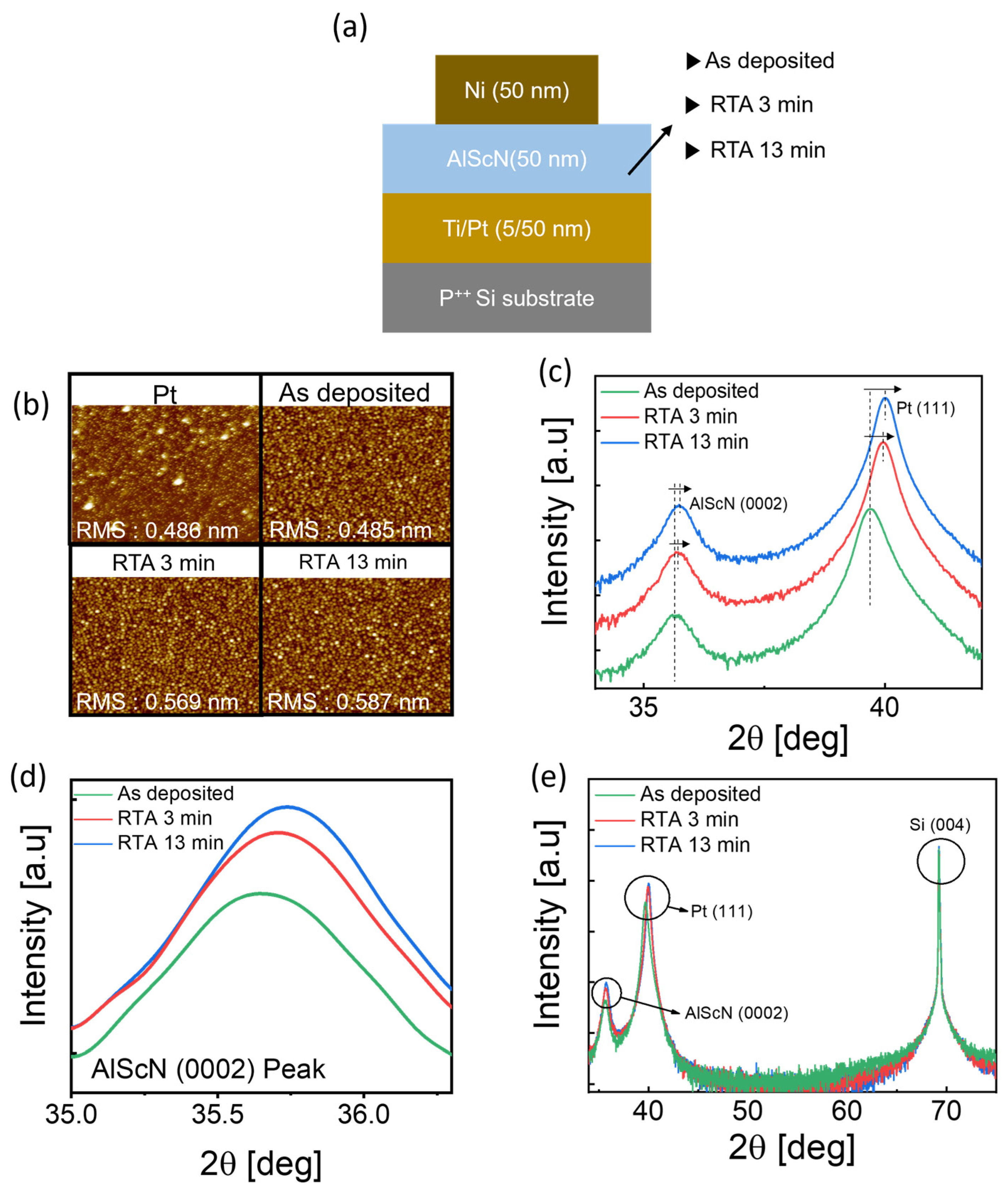
Figure 1. (a) Cross-sectional schematic of the MFM structure. (b) Comparison of AFM images and RMS roughness values. (c) XRD patterns (2θ = 32–42°) of as deposited, 3 min annealed, 13 min annealed AlScN film and (d) an enlarged view of the AlScN (0002) peak. (e) presents the overall XRD pattern.
Electronics 14 04353 g001
Figure 2. XPS depth profiles measured from (a) as deposited, (b) 3 min annealed, and (c) 13 min annealed AlScN MFM capacitors. (d) Schematic representation of chemical changes inside the AlScN.
Electronics 14 04353 g002
Figure 3. Output current from PUND measurements of (a) as deposited and (b) 3 min annealed devices. (c,d) P-E loops measured in the voltage range of 30–39 V for as-deposited and 3 min annealed. (e) P–E loops at 39 V for devices with different annealing times. (f) Switching current characteristics as a function of annealing time.
Electronics 14 04353 g003
Figure 4. (a) Relative permittivity-electric field (εr-E) curves of AlScN devices annealed for different durations. (b) Variation in relative permittivity (εr) as a function of annealing time. (c) Log-scale leakage current of AlScN devices as a function of annealing temperature. (d) Linear-scale leakage current with an inset showing the leakage current at E = 3 MV/cm.
Electronics 14 04353 g004
Figure 5. Retention characteristics of AlScN devices with different annealing times: (a) overall retention performance, (b) change in remanent polarization (Pr) after 1000 s, and (c) retention loss at 1000 s. (d) Endurance cycling characteristics.
Electronics 14 04353 g005
Figure 6. Statistical scatter plots summarizing the overall electrical characteristics of AlScN capacitors with different annealing times: (a) remanent polarization (P–E) characteristics obtained from PUND measurements, (b) capacitance–voltage (C–V) behavior, (c) leakage current density (J–E) characteristics, (d) retention loss after electrical stress, and (e) endurance cycling performance.
Electronics 14 04353 g006
Table 1. Benchmarking table of ferroelectric capacitor.
FerroelectricStructureLeakage Current
Density (A/cm2)
Cycles
Al0.7Sc0.3N [39]Pt/AlScN/Ptn/a2.7 × 105
Al0.72Sc0.28N [40]Pt/AlScN/Ni2 × 10−2 to 10−71 × 104
Al0.72Sc0.28N [40]Pt/HfO2/AlScN/Ni3 × 10−4 to 10−71 × 105
Al0.88Sc0.12N [41]TiN/AlScN/TiN1 × 10−72 × 107
Al0.78Sc0.22N [42]Mo/TiN/HZO/Mon/aUnder 1 × 10⁴
This workPt/AlScN/Ni7 × 10−25 × 103
Disclaimer/Publisher’s Note: The statements, opinions and data contained in all publications are solely those of the individual author(s) and contributor(s) and not of MDPI and/or the editor(s). MDPI and/or the editor(s) disclaim responsibility for any injury to people or property resulting from any ideas, methods, instructions or products referred to in the content.