Abstract
This paper presents a novel hybrid modulation technique for Asymmetrical Cascaded H-Bridge Multilevel Inverters (ACHBMLIs), specifically designed to enhance both efficiency and harmonic performance. Unlike conventional strategies, the proposed method optimizes the switching scheme by operating the high-voltage H-Bridge at the fundamental frequency, thereby significantly reducing switching losses while maintaining low harmonic distortion levels comparable to traditional Pulse Width Modulation (PWM). To assess the effectiveness of the approach, a comprehensive comparison was conducted against two widely adopted modulation techniques for ACHBMLIs: Multicarrier Pulse Width Modulation (MPWM) and the Staircase Modulation Strategy (SMS). The evaluation involved both simulation and real-time Hardware-in-the-Loop (HIL) testing of a 7-level three-phase ACHBMLI, with a focus on key performance indicators such as voltage and current harmonic distortion, as well as converter efficiency. The results demonstrate that the proposed hybrid modulation achieves higher efficiency than PWM and lower current Total Harmonic Distortion (THD) than SMS. These findings highlight the potential of the hybrid strategy as a compelling solution for applications that demand an optimal balance between energy efficiency and waveform quality.
1. Introduction
Multilevel Inverters (MLIs) are increasingly favored by researchers in both industry and academia for high-power electronics applications. Their growing popularity is attributed to several key advantages, including modularity, low switching frequency, reduced output filter volume, and minimal Electromagnetic Interference (EMI) radiation. These features make multilevel inverters efficient and reliable for handling high power levels.
In addition to these advantages, MLIs are crucial in advancing transportation electrification and integrating renewable energy into the electrical grid [1,2]. Among the various MLI topologies discussed in the literature [3], the Cascaded H-bridge Multilevel Inverter (CHBMLI) is widely adopted due to its modular design and fault-tolerant capability. This topology allows for increased voltage levels by adding additional H-bridge modules [4], making it a flexible solution for various applications. However, CHBMLIs require separate DC sources, which limits their applicability to systems where such sources are readily available, including photovoltaic systems [5,6,7] hybrid energy storage systems [8,9], electric drives [10] and automotive applications [11]. Furthermore, CHBMLIs are particularly well-suited for grid-connected applications, where they can be utilized as a Static Synchronous Compensator (STATCOM) to regulate voltage [11,12].
However, to increase the number of generated levels, it is necessary to add more cascaded H-bridges, making the system more complex. Therefore, an alternative approach is the use of Asymmetric Multilevel Inverters (AMLIs), which help reduce the number of required power components. AMLI architectures are designed by applying different voltage amplitudes across the DC-link capacitors. This method allows for an increase in voltage levels while preserving the same hardware setup compared to symmetric configurations, leading to reduced overall costs. Numerous researchers have introduced innovative asymmetric topologies. For instance, in Ref. [13], the authors analyzed the performance of a novel MLI structure capable of generating an output voltage with 13 levels in a symmetric configuration, while in an asymmetric configuration, it can produce a 17-level output waveform, achieving a THD of 3% and an efficiency of 97%. The advanced K-type AMLI proposed in Ref. [14] demonstrated the highest experimental efficiency of 96.74%, with an output voltage THD of 5.3% without filters. Among the recently proposed AMLIs, a notable and efficient solution is the ACHBMLI [15], which retains all the benefits of the CHBMLI structure while enabling higher voltage levels through the appropriate selection of DC voltage amplitudes without requiring additional H-bridge modules and maintaining low hardware complexity. The literature identifies two approaches for selecting DC voltage amplitudes: the binary method, where the voltage ratio among DC sources follows a 1:2:4… progression, and the tertiary method, characterized by a 1:3:9… ratio [16]. A notable improvement is discussed in Ref. [17], where the ratio among the three sources of ACHBMLI is set to 1:2:6.
A widely discussed topic in the literature is the modulation techniques used to generate signals for driving the switches of converters. This subject is particularly important because these techniques significantly affect the performance of converters in terms of power dissipation and the harmonic content of the generated voltages. Based on the operating switching frequency, these techniques can be classified as follows, based on the frequency modulations:
- Low-frequency modulation techniques, such as Refs. [18,19,20]. According to Refs. [17,21] staircase modulation is the most suitable method for controlling an ACHBMLI converter. This strategy enables the generation of a staircase voltage waveform through a simple real-time algorithm that can be implemented on standard electronic devices. However, its main drawback is the presence of low-order voltage harmonics.
- High-frequency modulation techniques, such as MPWM [22,23,24], enabling the generation of current with low THD. However, the large number of switching events substantially increases switching losses.
Recently, researchers have explored hybridizing existing PWM strategies to leverage their advantages. For instance, a hybrid multicarrier PWM method for CHBMLIs is presented in Ref. [25], where two legs of each H-bridge cell operate at different switching frequencies to reduce switching events. However, this approach produces an unbalanced switching loss distribution, leading to varying device lifetimes among H-bridge cells. Another hybrid PWM technique, proposed in Ref. [26], aims to improve lower-order harmonics and minimize output voltage errors. However, it suffers from increased harmonic content when the carrier frequency is low. Additionally, a PWM method combining steady-state Nearest Level (NL) PWM and transient Carrier-Based (CB) PWM is introduced in Ref. [27] for motor drive applications. While effective in such contexts, its output current harmonic performance degrades when applied in grid-connected systems.
In Ref. [28], a hybrid PWM technique that integrates Nearest Level (NL) PWM and Carrier-Based (CB) PWM to optimize switching loss and harmonic distortion. Particle Swarm Optimization (PSO) is employed to determine the optimal hybridization level, minimizing power loss while ensuring compliance with grid code standards. The approach is experimentally validated on an MLI across various modulation indices. In Ref. [29], a hybrid modulation scheme is implemented for an ACHBMLI-STATCOM with a 1:2:6 DC voltage ratio, maximizing output voltage levels. Different H-bridges operate at varying switching frequencies to reduce losses and improve efficiency. Experimental results confirm effective reactive power.
In general, hybrid or modified modulation techniques are often employed to overcome the limitations of conventional approaches. For instance, in Ref. [30], a modified variable carrier-based discontinuous PWM strategy was proposed and implemented on a three-level inverter. The method achieves harmonic performance comparable to Selected Harmonic Elimination Pulse Width Modulation (SHEPWM) at low carrier ratios while overcoming the drawback of slow dynamic response.
However, hybrid modulation techniques can also be applied to DC-link capacitor voltage balancing, as demonstrated in Ref. [31] for a four-level Neutral-Point Clamped (NPC) inverter. The proposed method combines a three-level Space Vector Pulse Width Modulation (SVPWM) and a two-level PWM technique. A major strength of this approach lies in its ease of implementation on digital hardware, since the modulation process is almost identical to that of conventional SVPWM.
In Refs. [32,33], a hybrid technique combining two carrier signals with different frequencies was proposed to reduce switching losses in VSI inverters. A comprehensive analysis, including comparative evaluations with conventional and ripple-elimination methods, demonstrates the superiority of the proposed approach. The results show a significant reduction in current ripples while maintaining the full five-level output voltage, thus enhancing both reliability and efficiency in V2G systems. Specifically, the proposed method eliminates current ripples at their peak regions by synchronizing the switching signals of the power devices.
In Ref. [34], a modified carrier-based pulse-width modulation algorithm, termed per-phase discontinuous PWM, was introduced to generate different non-switching intervals for the phase leg most affected by aging, by injecting an appropriate zero-sequence voltage into the reference signals. These non-switching intervals prevent certain phase legs from commutating, thereby reducing switching frequency and corresponding losses. The careful design of variable clamping intervals enables a desirable decrease in per-phase switching frequency for two-level, three-phase voltage source inverters, while ensuring that the output performance remains largely unaffected.
As described in the literature, hybrid or modified modulation techniques are often employed to balance DC-link voltages in NPC inverters or to reduce current ripple. In this work, however, we propose a hybrid modulation technique aimed at improving efficiency while preserving excellent harmonic performance in both load voltage and current. Unlike the approaches commonly found in the literature, the proposed technique is specifically designed to be suitable for ACHBMLI configurations.
To validate the proposed method, a comprehensive comparative analysis is conducted against the two most widely adopted ACHBMLI modulation strategies reported in the literature, PWM, known for its high-quality voltage output, and SMS, recognized for its high efficiency and reduced switching losses. The proposed modulation is further distinguished by the inclusion of a thermal stress assessment, an aspect often overlooked in previous work, thus providing deeper insight into the reliability of the power devices.
Finally, this study demonstrates that a fundamental-frequency switching scheme can be effectively integrated with high-frequency modulation without compromising grid compliance or drive performance. The presented results—covering voltage and current quality, converter losses, efficiency, and thermal behavior—offer a comprehensive evaluation framework and extend the current understanding of asymmetric multilevel inverter performance
2. Mathematical Model of the ACHBMLI
The system analyzed in this article is shown in Figure 1. It consists of a three-phase seven-level (3-P 7-L) ACHBMLI, which is composed of six H-bridges. Each inverter leg consists of two cascaded H-bridges configured asymmetrically, meaning that the two bridges operate at different DC voltage levels. Specifically, HBb is the H-bridge with twice the DC voltage of the other bridge, referred to as HBa.
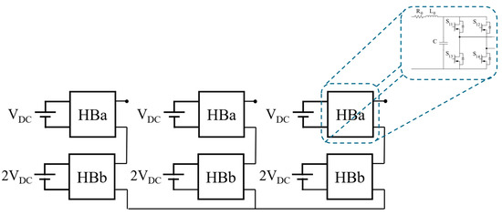
Figure 1.
Three-phase 7-level ACHBMLI.
As previously mentioned, AMLIs allow for a higher number of voltage levels while maintaining the same hardware configuration as an MLI. For an ACHBMLI in a binary configuration, the number of voltage levels , as reported in Ref. [35], is given by:
The mathematical model of a generic phase ACHBMLI is described as follows:
here, HBb represents the H-bridge with a DC-link voltage that is twice that of HBa. The output voltages of HBa and HBb are denoted as and , respectively. The gate signals of the asymmetric inverter are and , while and represent the input currents of the H-bridges. The voltages across the respective DC-link capacitors are and . The circuit parameters are: C DC-link capacitance, and are, respectively, the resistance and inductance of the power supply circuit.
To develop a model that accounts for diode current conduction, the Generalized Switching Functions (GSF) [36] must be implemented, as shown in Equation (5)
The efficiency of an ACHBMLI is influenced by several factors, primarily related to power losses occurring during operation. These losses can be categorized into switching losses and conduction losses . Switching losses arise during the turn-on and turn-off transitions of the power semiconductors and are affected by switching frequency, semiconductor characteristics, and modulation techniques. While higher switching frequencies enhance output voltage quality, they also lead to increased losses. Conduction losses, on the other hand, occur when power devices are in the ON state and depend on their internal resistance and current flow. Thus, the efficiency of an inverter is determined using the following formula:
where represents the efficiency of the ACHBMLI, is the input power.
Several factors impact the overall efficiency of the converter. The modulation strategy plays a crucial role, as different techniques, such as SMS or PWM, influence how losses are distributed and how efficiently the converter operates. The selection of semiconductor components, such as IGBTs or SiC MOSFETs, also affects switching and conduction losses. Thermal management is another critical factor, as higher temperatures increase resistance and switching times, ultimately reducing efficiency. Additionally, load conditions significantly impact performance, as efficiency varies with the modulation index and load demand. At lower modulation indices, harmonic distortion tends to increase, which can degrade the overall efficiency.
By optimizing switching strategies, ACHBMLIs can achieve higher efficiency, which is particularly important in automotive applications, where reducing losses directly contributes to extended vehicle range and improved energy utilization.
The other important parameter analyzed is the THD, which is crucial for evaluating the quality of the output voltage and current in an ACHBMLI. It quantifies the distortion introduced by the presence of harmonic components in the waveform, which can negatively impact the performance of electrical drives and grid-connected systems. A lower THD ensures better power quality, reducing additional losses in the motor and minimizing electromagnetic interference. THD is calculated using the following formula:
where represents the rms voltage of the n-th harmonic component, and is the rms voltage of the fundamental frequency. Several factors affect THD levels in an ACHBMLI. The modulation strategy plays a key role, as different frequency modulation techniques present trade-offs between harmonic content and efficiency. The switching frequency also significantly impacts higher frequencies shift harmonic components to higher orders, making them easier to filter. However, this comes at the cost of increased power losses. The modulation index further influences THD, as lower modulation indices typically lead to a rise in low-order harmonics, degrading waveform quality. Finally, load conditions contribute to THD variations, as changes in speed and torque in electrical drive applications can cause variations in harmonic content.
3. Proposed Modulation Technique
This section provides a detailed description of the modulation techniques proposed. The two most widely used modulation techniques for ACHBMLIs are Multicarrier (MC)-PWM and SMS, each offering distinct advantages and drawbacks.
MC-PWM is highly effective in reducing harmonic content as its high-frequency harmonics are concentrated at multiples of the carrier frequency, making them easier to filter. As a result, in electrical drive applications, the stator currents exhibit very low THD, thereby enhancing overall system performance [37]. However, its main drawback is the high switching frequency, which leads to greater power dissipation in the inverter. This limits its applicability in medium-voltage, low-power systems, where minimizing power losses is critical.
SMS offers a key advantage in its low switching frequency. The main H-Bridge switches operate at a frequency equal to the modulation signal, significantly reducing switching losses and improving efficiency. By concentrating on switching events on the lower voltage modules, SMS enhances the power conversion efficiency of ACHBMLIs, making it a practical choice for various applications. However, its major limitation lies in the presence of low-order harmonics. While the overall THD remains relatively low, certain modulation indices can introduce problematic harmonics into the system. These harmonics may lead to increased torque ripple and degradation of the current waveform quality, potentially impacting the overall performance and efficiency of the drive [38].
A hybrid approach was developed to overcome those trade-offs. It integrates SMS and PD-PWM to achieve balanced power loss distribution and improved harmonic performance. This hybridization ensures low THD while maintaining switching losses and enhancing the efficiency of ACHBMLIs.
The PD-PWM technique, due to its high switching frequency, leads to increased switching losses, whereas the SMS, operating at a frequency comparable to the fundamental one, results in significantly lower switching losses. To address this trade-off, the proposed hybrid modulation technique was designed to combine the strengths of both strategies while mitigating their respective drawbacks. Figure 2 illustrates the operating principle of the proposed modulation scheme. The process of generating the HBb control signals remains the same as in SMS; however, the main distinction lies in the adoption of a high-frequency carrier signal to generate the control signals for HBa, which directly influences the system’s switching characteristics and harmonic performance.
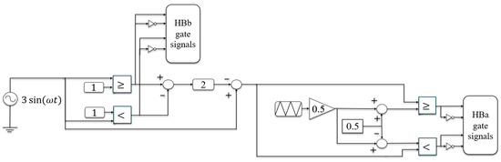
Figure 2.
Principle of the proposed hybrid modulation technique operation for a 7-L ACHBMLI.
In this approach, the two H-bridges operate at different switching frequencies, allowing for an optimized balance between efficiency and harmonic performance. The HBb bridge switches at a frequency equal to the fundamental frequency, significantly reducing switching losses, while the HBa bridge operates at a higher switching frequency, typically in the kHz range.
In general, the switching losses for a single switch can be calculated using the following expression:
these losses depend on several factors: which represents the voltage of the compensator feeding the H-bridge of the generic component; the load current; and the turn-on and turn-off times of the switch; and the switching frequency. This applies to the losses of a single switch; however, to adapt it to the system under consideration, which consists of two cascaded H-bridges, one operating at twice the voltage of the other, the Equation (8) becomes:
where denotes the number of switches in each H-bridge, which in this case is always equal to 4. The same equation adapted to PD-PWM is:
where is the switching frequency associated with the PWM technique, which is typically in the order of kHz.
For the SMS technique the (9) became:
where is the fundamental frequency, typically a few Hz. The same Equation (9), adapted to proposed hybrid modulation, becomes:
In conclusion, it has been demonstrated that the proposed hybrid modulation allows to reduce the switching losses respect to the MC PWM scheme. Therefore:
Considering (14), it can be stated that the switching losses of the hybrid technique are higher than those of the SMS technique. Consequently, a converter employing the hybrid technique will inevitably exhibit lower efficiency compared to the SMS case. However, as will be demonstrated in the following sections, the hybrid technique produces waveforms free from low-frequency harmonics, which represents a crucial advantage in various applications. For instance, in electrical drive systems, the presence of such harmonics poses a fundamental issue, as they directly impact torque ripple and the overall performance of the drive.
4. Simulation Results
Simulation results are presented in this Section to compare the performance of a 3-P 7-L ACHBMLI under different modulation techniques. The analysis primarily examines the harmonic distortion present in the output voltages and currents, providing insights into the performance of each modulation technique. It should be emphasized that each modulation technique is applied individually in simulation and HIL testing. The comparison focuses on an in-depth analysis of the harmonic content of the output voltages and currents. The system under study, shown in Figure 3, consists of a 3-phase, 7-level ACHBMLI connected to a passive load composed of a resistor in series with an inductor. The parameters of both the ACHBMLI and the load are provided in Table 1.
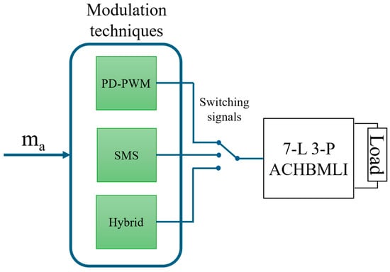
Figure 3.
Block diagram of the modulation strategies applied to the 7-L 3-P ACHBMLI with a passive load.

Table 1.
Data of ACHBMLI and passive load.
The comparison is carried out by analyzing the output voltage waveform corresponding to each modulation technique. A key aspect of the evaluation is the harmonic spectrum of both voltage and current, along with their THD, which is essential for assessing power quality. The simulations were performed using a MATLAB/Simulink R2024b model, enabling an accurate representation of the system’s behavior under various modulation strategies.
A key factor analyzed in this study is the quality of the output voltage waveform generated by the 7-level three-phase ACHBMLI. Figure 4 presents a comparison of the voltage waveforms and their corresponding harmonic spectra for the three implemented modulation techniques. The analysis was conducted under operating conditions with a modulation index (ma) of 0.95, chosen to represent a relevant and practical scenario for evaluating both harmonic content and overall waveform quality across different modulation strategies. However, the fundamental frequencies, as well as the frequency of the modulation signal, are equal to 50 Hz, whereas the switching frequency depends on the modulation technique used. For instance, with SMS the switching frequency is equal to the fundamental frequency, while for PWM it depends on the carrier frequency, which in this case is 10 kHz.
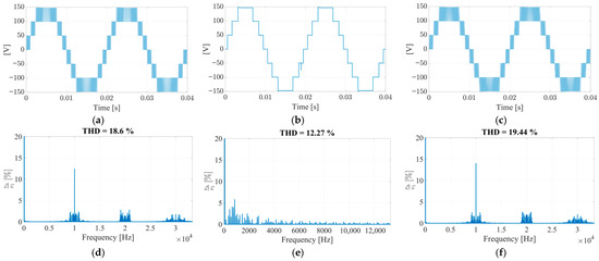
Figure 4.
Waveforms and harmonic spectra of the voltage for the analyzed modulation techniques: (a) PD-PWM voltage, (b) SMS voltage, (c) hybrid voltage, (d) harmonic spectrum of PD-PWM, (e) harmonic spectrum of SMS, (f) harmonic spectrum of the hybrid technique.
The voltage phase waveforms are shown in Figure 4a–c. It can be observed that the waveform produced by the SMS technique features fewer switching transitions and is composed of well-defined voltage steps. In contrast, both PWM and hybrid techniques result in waveforms with a greater number of pulses. This difference stems from the switching frequency: SMS operates at a lower switching frequency, resulting in fewer transitions, while PWM and hybrid techniques employ higher switching frequencies, producing smoother and more refined voltage waveforms.
The corresponding harmonic spectra, depicted in Figure 4d–f, reveal significant differences in harmonic distribution among the three techniques.
The PWM spectrum is dominated by high-frequency harmonics, primarily concentrated around multiples of the modulation frequency (10 kHz), although some low-frequency components are still present. Conversely, the SMS technique introduces predominantly low-frequency harmonics, which may adversely affect system performance especially in sensitive applications such as electric drives. The HBR spectrum closely resembles that of PWM but exhibits a notable reduction in low-frequency harmonics, offering a more balanced trade-off between harmonic performance and switching losses.
The THD values of the output voltage for the PWM, SMS, and hybrid techniques are 18.6%, 12.27%, and 19.44%, respectively. At first glance, SMS seems to provide the best harmonic performance, as it yields the lowest THD value.
Indeed, as shown in Figure 5, the high-frequency harmonics are effectively filtered out by the load, leaving only the low-frequency components in the current waveform. As a result, the total harmonic distortion (THD) of the current supplied to the load when using SMS is 6.288%, whereas high-frequency modulation techniques achieve significantly lower values 0.949% for PWM and 1.008% for the hybrid technique. This confirms that while PWM and HBR generate harmonics primarily at higher frequencies, which are easier to attenuate, SMS introduces dominant low-frequency harmonics. This behavior is particularly advantageous in grid-connected applications, where strict power quality standards must be met, and high-frequency harmonics are more easily filtered by grid interface components, ensuring compliance with regulatory limits.
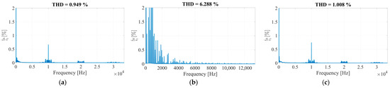
Figure 5.
Harmonic spectra of the current for the analyzed modulation techniques: (a) PD-PWM, (b) SMS, (c) hybrid technique.
5. Description of the Test Bench Equipment
This section overviews the test bench equipment utilised for real-time validation. Specifically, as illustrated in Figure 6, the controller is installed on the Power Electronics and Drive (PED) Board V4 (Elettronica Dedicata Inc.), whose main specifications are detailed in Table 2.
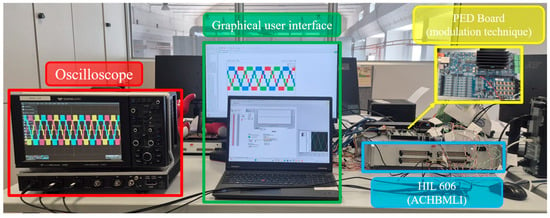
Figure 6.
Test bench equipment.
Table 2.
PED-Board V4 characteristics.
The modulation techniques are fully implemented using the LabVIEW graphical programming environment. The control architecture is structured into two fully parallel processing units. The first unit operates at high frequency and manages the modulator, including carrier signal generation, dead-time insertion, and gate signal production. The second unit is dedicated to data acquisition and modulation signal processing.
System initialization is synchronized to ensure that data sampling and control actions are triggered precisely at the peak and valley points of the carrier waveform. Consequently, the effective sampling frequency is twice the virtual switching frequency.
The 7-L 3-P ACHBMLI and the passive load under test are simulated in real time using the Typhoon HIL 606 Hardware-in-the-Loop platform. The scheme implemented in the HIL 606 is shown in Figure 6. The HIL 606 receives the switch control signals from the PED-Board, which allows the output voltage and current of the 7-L 3-P ACHBMLI, implemented directly within the HIL 606, to be generated in real time. The main features of this system are summarized in Table 3. For enhanced realism, the ACHBMLI has been fully integrated into the HIL environment to enable accurate real-time emulation. Moreover, this system allows loading the datasheet parameters of the electronic components to emulate their behavior. This capability makes it possible to estimate the converter losses, enabling the determination of the ACHBMLI efficiency and the analysis of its variation with different modulation techniques.
Table 3.
HIL 606 characteristics.
6. Real-Time Validation
In this section, the real-time validation of the modulation strategies under investigation was performed. For each experimental trial, the microcontroller was reset and the subsequent modulation technique was initialised.
Specifically, several real-time validation tests were conducted using the test bench shown in Figure 7 to compare the harmonic content of the generated voltages and currents, their THD and the efficiency of the power converter. Furthermore, with the HIL 606 platform, it is possible to monitor the temperature of each ACHBMLI component, enabling the study of thermal behaviour under different modulation techniques and assessing the thermal stress experienced by the power devices. Additionally, the parameters of the passive load and the ACHBMLI are the same as those in the previous Section 4, as described in Table 1.
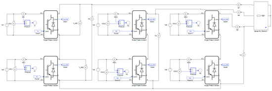
Figure 7.
7-L 3-P ACHBMLI implemented in the HIL606.
It is essential to analyse the voltage spectra for the three modulation techniques. The spectral analysis provides deeper insight into the harmonic content of the generated waveforms, highlighting the impact of each modulation strategy on power quality. In the following section, the voltage spectra obtained from real-time validation are compared to assess the distribution of harmonics and their effects on the system. In this case, the reported line voltages are relative to operating conditions in which the modulating index is slightly less than one, precisely equal to 0.95.
Figure 8 shows the waveforms of the line voltages and their respective spectra. In the case of PWM, the spectrum primarily contains harmonics multiples of the switching frequency (10 kHz), which are easily filtered by the load. Conversely, the SMS modulation spectrum exhibits significant low-frequency harmonics, while those above 10 kHz are of negligible magnitude. Particularly interesting is the analysis of Figure 8c, which relates to the hybrid technique: Although the HBb bridge switches at the fundamental frequency, the only harmonics present are multiples of 10 kHz, similar to PWM. The THD values of the output voltage for the PD-PWM, SMS, and hybrid techniques are 18.6%, 12.2%, and 19.44%, respectively.
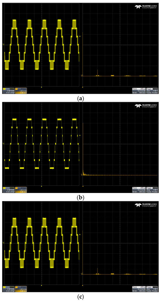
Figure 8.
Waveforms and harmonic spectra of the voltage for the evaluated modulation techniques in real-time validation: (a) PD-PWM, (b) SMS, (c) hybrid.
Indeed, as shown in Figure 9, the high-frequency harmonics are effectively filtered out by the load, leaving only the low-frequency components in the current waveform. As a result, the THD of the current supplied to the load when using SMS is 6.288%, whereas high-frequency modulation techniques achieve significantly lower values 0.949% for PWM and 1.008% for the hybrid technique. This confirms that while PWM and HBR generate harmonics primarily at higher frequencies, which are easier to attenuate, SMS introduces dominant low-frequency harmonics.
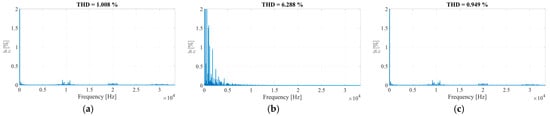
Figure 9.
Harmonic spectra of the load current for the evaluated modulation techniques in real-time validation: (a) PD-PWM, (b) SMS, (c) hybrid technique.
Additionally, an extensive series of tests was performed to compare the three modulation techniques in terms of voltage THD (THDV), current THD (THDI), and efficiency (η) of the ACHBMLI. The assessment was conducted under various operating conditions, with a ma ranging from 0.2 to 1, comprehensively evaluating each technique’s performance.
Additional tests were carried out to evaluate how the voltage and current vary following a change in load, specifically when the load is halved while maintaining a constant power factor. The results are presented in Figure 10. As can be observed, when the load is reduced, the voltage remains constant and is not affected by the variation, whereas the current increases for all modulation techniques. It should also be noted that no substantial differences are observed among the modulation techniques.
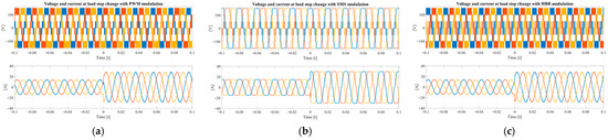
Figure 10.
System step response as the modulation technique changes: (a) PD-PWM, (b) SMS, (c) hybrid technique.
In Figure 11, the THD values of both voltage and current THD are shown for different operating. Generally, regardless of the modulation strategy employed, increasing the modulation index results in a reduction in both THDV and THDI. It can generally be stated that the SMS technique achieves better harmonic performance, especially at higher ma values, although the results remain comparable to those of the other two modulation methods. PWM and the hybrid approach consistently yield almost identical THDV values.
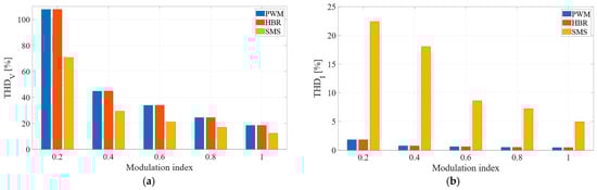
Figure 11.
THD values under different operating conditions using three modulation techniques: (a) THDV; (b) THDI.
Although the THDV values for the three modulation techniques are comparable, their harmonic content is entirely different, as previously discussed. As a result, their THDI values vary significantly. In particular, the THDI of SMS is consistently much higher than that of PWM and the hybrid technique.
This difference arises because the low-frequency harmonics present in the SMS-generated voltage cannot be effectively filtered by the load, unlike the high-frequency harmonics found in PWM and hybrid modulation. Since PWM and HBR primarily produce high-order harmonics, they are more easily filtered, resulting in a current waveform much closer to an ideal sinusoid. Indeed, the THDI associated with the SMS technique varies between 22% and 5%, while for both PWM and the hybrid approach, the maximum observed value is around 1.8%, decreasing to approximately 0.46% when ma equals 1.
Since PWM and HBR techniques primarily generate high-frequency harmonics, which are more easily filtered, the resulting current waveform is much closer to an ideal sinusoid, leading to reduced torque ripple and smoother motor operation This aspect is particularly critical in several applications where maintaining sinusoidal current waveforms is essential, for instance, in electric drive systems, where such current profiles lead to a substantial reduction in torque ripple.
Analysing the efficiency of the converter under various operating conditions and for the three modulation techniques provides valuable insights. Also in this case, the modulation index varies from 0.2 to 1. As shown in Figure 12, the modulation strategy has a significant impact on the efficiency of the ACHBMLI, primarily due to differences in switching frequency. The SMS technique consistently achieves the highest efficiency across all operating conditions, as its switching frequency is significantly lower compared to the other modulation strategies, leading to reduced switching losses.
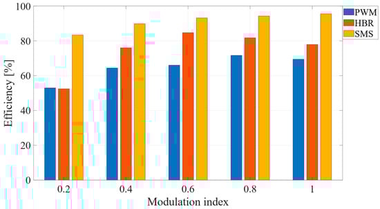
Figure 12.
Efficiency values of the 7-L 3-P ACHBMLI under different operating conditions using the three modulation techniques.
However, the proposed hybrid modulation technique offers a notable improvement in efficiency over the conventional PWM approach. This enhancement is mainly because the HBb switches at a frequency equal to the fundamental component, which drastically reduces switching losses compared to PWM, where all bridges switch at high frequency.
The higher efficiency of the SMS technique is attributed to the presence of low-frequency isofrequency components in both voltage and current spectra, which contribute to the active power. In contrast, PWM and HBR techniques operate at higher switching frequencies, resulting in increased switching losses. To further illustrate the impact of these losses, Figure 13 presents the distribution of both conduction and switching losses. It can be observed that PWM and HBR exhibit considerably higher switching losses compared to SMS, leading to superior overall efficiency for the latter. However, conduction losses are slightly higher in the SMS case. Consequently, the HBR technique represents a reasonable compromise between switching and conduction losses, offering a balanced trade-off between efficiency and thermal performance.
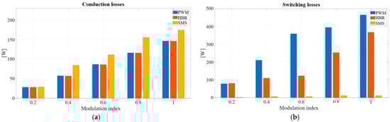
Figure 13.
Converter losses for the three modulation techniques at different modulation indices: (a) conduction losses; (b) switching losses.
To highlight the impact of carrier frequency on the efficiency of the ACHBMLI, real-time tests were conducted with carrier frequencies of 5, 10, and 15 kHz for both the PD-PWM and HBR techniques. This analysis does not include SMS, since this technique operates at a constant switching frequency. As shown in Figure 14, for the same switching frequency and modulation index, the HBR technique consistently exhibits higher efficiency compared to PD-PWM. In general, it can be observed that increasing the switching frequency leads to reduced efficiency. This effect is more pronounced in the case of PD-PWM, where at 15 kHz the efficiency drops below 20%, whereas for HBR, even in the worst case, it remains above 30%. It should be noted that this study considers only the variation in switching frequency, although efficiency also depends on other factors such as dead time and the amplitude modulation index, as demonstrated in Ref. [23].
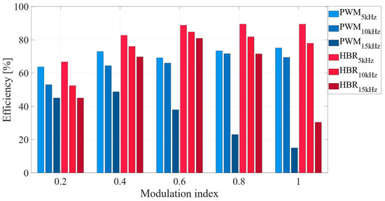
Figure 14.
Efficiency values of the 7-Level Three-Phase ACHBMLI under different operating conditions with varying switching frequency.
Finally, based on the previously discussed results, it can be stated that the proposed hybrid modulation technique delivers highly satisfactory performance across all analyzed aspects:
- Superior harmonic performance: the harmonic content of both voltage and current is very similar to that of PWM, with dominant harmonics located in the kHz range. This makes them easier to filter, which is particularly advantageous in grid-connected applications. As a result, the THDI is significantly lower compared to SMS, bringing multiple benefits for instance, in electric drive applications, it leads to reduced torque ripple and smoother motor operation.
- Higher efficiency compared to PWM: While the efficiency of the hybrid technique remains lower than SMS, it is significantly higher than PWM in most operating conditions.
7. Conclusions
This work proposed and validated a novel and innovative modulation technique through a comprehensive comparison with the two most widely used techniques for ACHBMLIs. To ensure a thorough evaluation, extensive testing was carried out through both simulations and real-time validation on an ACHBMLI prototype connected to a passive load consisting of a resistor and an inductor. These tests were systematically performed for MC-PWM, SMS, and the proposed hybrid technique, allowing for a detailed performance assessment.
The study analyzed several key aspects, including the harmonic content and THD of both phase voltages and currents, as well as the efficiency of the converter under various operating conditions. The results highlighted that SMS achieves the highest efficiency due to its lower switching frequency, but it suffers from significantly low-frequency harmonics, which negatively impact the performance. Conversely, MC-PWM provides good harmonic quality, particularly in the generated current, but at the cost of higher switching losses, reducing the overall system efficiency.
The hybrid modulation technique successfully balances efficiency and harmonic performance by combining the advantages of both SMS and MC-PWM. The results demonstrated that the proposed technique maintains a low THDI, similar to PWM, while significantly reducing switching losses by operating HBb at the fundamental frequency. This results in an overall improvement in converter efficiency compared to PWM. This is a good result because it makes the hybrid strategy suitable for practical applications where both low harmonic distortion and acceptable efficiency are required.
In conclusion, although the results obtained in this study are promising, further experimental validation will be necessary in the future. The same tests performed in simulations and real-time validation should be conducted on a physical prototype to confirm the effectiveness of the proposed hybrid modulation technique under real operating conditions. Experimental testing will provide deeper insights into practical implementation challenges, such as thermal behavior and electromagnetic interference, ensuring that the proposed approach remains a viable and efficient solution.
Author Contributions
Conceptualization, G.S., G.F. and M.C.; methodology, G.S.; software, G.F.; writing—original draft preparation, G.F.; writing—review and editing, M.C.; supervision, M.C. and R.M. All authors have read and agreed to the published version of the manuscript.
Funding
This research was funded by the European Union—NextGenerationEU—National Sustainable Mobility Center CN00000023, Italian Ministry of University and Research Decree n. 1033— 17/06/2022, Spokes 2, 3, 9 and 12, CUP B73C22000760001, by the project “SiciliAn MicronanOTecH Research And Innovation CEnter “SAMOTHRACE” (MUR, PNRR-M4C2, ECS_00000022), spoke 1 and spoke 3—Università degli Studi di Palermo “S2-COMMs—Micro and Nanotechnologies for Smart & Sustainable Communities”, by the project “Network 4 Energy Sustainable Transition—NEST”, CUP B73C22001280006, Project code PE0000021, Concession Decree No. 1561 of 11.10.202, by the OPTEBUS project (Development of an Optimal Design Tool for Electrification of Urban Public Transportation BUS Services)—PRIN Progetti di Rilevante Interesse Nazionale 2022- CUP: B53D23002860006, by the ESPFET project (Enhanced Energy-Saving Powertrains for Freight E-Transportation)—PRIN Progetti di Rilevante Interesse Nazionale 2022- CUP: B53D23002440006.
Data Availability Statement
The original contributions presented in this study are included in the article. Further inquiries can be directed to the corresponding author.
Acknowledgments
This work was carried out in the following laboratories: Sustainable Development and energy saving laboratory (SDESLab), Rapid Prototyping Lab (RPLab), Laboratory of Applied Electrotechnics (LEAP) at the Department of Engineering, Building no.9, University of Palermo, Italy.
Conflicts of Interest
The authors declare no conflicts of interest.
References
- Vijeh, M.; Rezanejad, M.; Samadaei, E.; Bertilsson, K. A General Review of Multilevel Inverters Based on Main Submodules: Structural Point of View. IEEE Trans. Power Electron. 2019, 34, 9479–9502. [Google Scholar] [CrossRef]
- Taha, T.A.; Shalaby, M.; Wahab, N.I.A.; Zaynal, H.I.; Hassan, M.K.; Al-Sowayan, S.; Alawad, M.A. Recent Advancements in Multilevel Inverters: Topologies, Modulation Techniques, and Emerging Applications. Symmetry 2025, 17, 1010. [Google Scholar] [CrossRef]
- Rashid, M.H. Power Electronics Handbook: Devices, Circuits, and Applications; Prentice Hall: Hoboken, NJ, USA, 2014. [Google Scholar]
- Rodríguez, J.; Lai, J.S.; Peng, F.Z. Multilevel inverters: A survey of topologies, controls, and applications. IEEE Trans. Ind. Electron. 2002, 49, 724–738. [Google Scholar] [CrossRef]
- Zhao, P.; He, X.; Qiu, C.; Wang, Y.; Han, X. A Novel Leakage Current Attenuation Method for Non-isolated Odd-module Cascade H-bridge in Single-Phase PV System. IEEE J. Emerg. Sel. Top. Power Electron. 2024, 12, 5100–5111. [Google Scholar] [CrossRef]
- Leon-Ruiz, Y.; Gonzalez-Garcia, M.; Alvarez-Salas, R.; Cardenas, V.; Diaz, R.I.V. Fault Diagnosis in a Photovoltaic Grid-Tied CHB Multilevel Inverter based on a Hybrid Machine Learning and Signal Processing Technique. IEEE Access 2024, 12, 128909–128928. [Google Scholar] [CrossRef]
- Karania, N.; Alali, M.A.; Di Gennaro, S.; Barbot, J.P. Advanced High Switching-Frequency Cascaded H-Bridge Multilevel Inverter Based Shunt Active Filter for PV Generation: A Case Study. IEEE Open J. Ind. Appl. 2025, 6, 262–280. [Google Scholar] [CrossRef]
- Gohari, A.; Althuwaini, H.; Shadmand, M.B. Optimal Utilization of Battery Sources in Cascaded H-Bridge Inverter by Coordinated Sequence Selection. IEEE Trans. Ind. Electron. 2024, 71, 10841–10853. [Google Scholar] [CrossRef]
- Gunsal, I.; Stone, D.A.; Foster, M.P. Suppressing Leakage Current for Cascaded H-Bridge Inverters in Renewable Energy and Storage Systems. IEEE Trans. Ind. Electron. 2021, 68, 11035–11043. [Google Scholar] [CrossRef]
- Nevoloso, C.; Foti, S.; Scaglione, G.; Di Tommaso, A.O.; De Caro, S.; Testa, A.; Miceli, R. On the Inadequacy of IEC 60034-2-3 and IEC 60034-30-2 Standards for Power Losses, Efficiency and Energy Class Evaluation in PWM Multilevel Inverter-Driven PMSM. IEEE Open J. Ind. Electron. Soc. 2025, 6, 962–981. [Google Scholar] [CrossRef]
- Kersten, A.; Theliander, O.; Grunditz, E.A.; Thiringer, T.; Bongiorno, M. Battery Loss and Stress Mitigation in a Cascaded H-Bridge Multilevel Inverter for Vehicle Traction Applications by Filter Capacitors. IEEE Trans. Transp. Electrif. 2019, 5, 659–671. [Google Scholar] [CrossRef]
- Farivar, G.; Hredzak, B.; Agelidis, V.G. Decoupled Control System for Cascaded H-Bridge Multilevel Converter Based STATCOM. IEEE Trans. Ind. Electron. 2016, 63, 322–331. [Google Scholar] [CrossRef]
- Al-Hitmi, M.A.; Hussan, R.; Iqbal, A.; Islam, S. Symmetric and Asymmetric Multilevel Inverter Topologies with Reduced Device Count. IEEE Access 2023, 11, 5231–5245. [Google Scholar] [CrossRef]
- Zeng, J.; Lin, W.; Cen, D.; Liu, J. Novel k-Type multilevel inverter with reduced components and self-balance. IEEE J. Emerg. Sel. Top. Power Electron. 2020, 8, 4343–4354. [Google Scholar] [CrossRef]
- Busarello, T.D.C.; Mortezaei, A.; Paredes, H.K.M.; Al-Durra, A.; Pomilio, J.A.; Simoes, M.G. Simplified Small-Signal Model for Output Voltage Control of Asymmetric Cascaded H-Bridge Multilevel Inverter. IEEE Trans. Power Electron. 2018, 33, 3509–3519. [Google Scholar] [CrossRef]
- Sajadi, R.; Iman-Eini, H.; Bakhshizadeh, M.K.; Neyshabouri, Y.; Farhangi, S. Selective harmonic elimination technique with control of capacitive DC-link voltages in an asymmetric cascaded H-Bridge Inverter for STATCOM Application. IEEE Trans. Ind. Electron. 2018, 65, 8788–8796. [Google Scholar] [CrossRef]
- Busarello, T.D.C.; De Sousa Marcondes Reuter, A.L.; Peres, A.; Simoes, M.G. Understanding the Staircase Modulation Strategy and Its Application in Both Isolated and Grid-Connected Asymmetric Cascaded H-Bridge Multilevel Inverters. IEEE Trans. Ind. Appl. 2019, 55, 5371–5382. [Google Scholar] [CrossRef]
- Kavousi, A.; Vahidi, B.; Salehi, R.; Bakhshizadeh, M.K.; Farokhnia, N.; Fathi, S.H. Application of the bee algorithm for selective harmonic elimination strategy in multilevel inverters. IEEE Trans. Power Electron. 2012, 27, 1689–1696. [Google Scholar] [CrossRef]
- Buccella, C.; Cimoroni, M.; Cecati, C.; Di Tommaso, A.O.; Nevoloso, C.; Schettino, G.; Meo, S. Investigation about selective harmonic elimination in unbalanced multilevel inverters. In Proceedings of the MELECON 2022—IEEE Mediterranean Electrotechnical Conference, Palermo, Italy, 14–16 June 2022; Institute of Electrical and Electronics Engineers Inc.: New York, NY, USA, 2022; pp. 1235–1240. [Google Scholar] [CrossRef]
- Sarbanzadeh, M.; Hosseinzadeh, M.A.; Salehi, A.; Rivera, M.; Wheeler, P. Genetic Algorithm Technique for 7-Level Cascaded H-Bridge Multilevel Converter THD Minimization. In Proceedings of the 2019 IEEE 28th International Symposium on Industrial Electronics (ISIE), Vancouver, BC, Canada, 12–14 June 2019. [Google Scholar]
- Busarello, T.D.C.; de Sousa Marcondes Reuter, A.L.; Péres, A.; Simões, M.G. Understanding the Staircase Modulation Strategy and its Application in Asymmetric Cascaded H-Bridge Multilevel Inverter. In Proceedings of the 2018 IEEE Industry Applications Society Annual Meeting (IAS), Portland, OR, USA, 23–27 September 2018; pp. 1–8. [Google Scholar] [CrossRef]
- Kouro, S.; Lezana, P.; Angulo, M.; Rodriguez, J. Multicarrier PWM with DC-link ripple feedforward compensation for multilevel inverters. IEEE Trans. Power Electron. 2008, 23, 52–59. [Google Scholar] [CrossRef]
- Schettino, G.; Di Tommaso, A.O.; Miceli, R.; Nevoloso, C.; Scaglione, G.; Viola, F. Dead-Time Impact on the Harmonic Distortion and Conversion Efficiency in a Three-Phase Five-Level Cascaded H-Bridge Inverter: Mathematical Formulation and Experimental Analysis. IEEE Access 2023, 11, 32399–32426. [Google Scholar] [CrossRef]
- Lemssaddak, S.; Ait Elmahjoub, A.; Tabaa, M.; El-Alami, A.; Zegrari, M. A Novel Multilevel Inverter Topology Generating a 19-Level Output Regulated by the PD-PWM Method. Energies 2025, 18, 3227. [Google Scholar] [CrossRef]
- Lee, E.J.; Kim, S.M.; Lee, K.B. Modified phase-shifted PWM scheme for reliability improvement in cascaded H-bridge multilevel inverters. IEEE Access 2020, 8, 78130–78139. [Google Scholar] [CrossRef]
- Zhang, Y.; Dai, K.; Xu, C.; Kang, Y.; Dai, Z. Multiple sampling PSC-PWM with hierarchical control architecture for MMC-DSTATCOM. IET Electr. Power Appl. 2019, 13, 1431–1440. [Google Scholar] [CrossRef]
- Huang, J.; Li, K. Suppression of common-mode voltage spectral peaks by using rotation reverse carriers in sinusoidal pulse width modulation three-phase inverters with CFM. IET Power Electron. 2020, 13, 1246–1256. [Google Scholar] [CrossRef]
- Bhowmick, S.; Vasu, R.; Chattopadhyay, S.K.; Chakraborty, C. A PSO-Based Optimized Hybrid PWM Strategy for a Binary Asymmetric Cascaded H-Bridge Photovoltaic Inverter with Single PV Source per Phase. IEEE J. Emerg. Sel. Top. Power Electron. 2024, 12, 1654–1665. [Google Scholar] [CrossRef]
- Karania, N.; Alali, M.A.; Di Gennaro, S.; Barbot, J.P. Developed AC/DC/AC Converter Structure Based on Shunt Active Filter and Advanced Modulation Approach for Asymmetrical Cascade H-Bridge Multilevel Inverters. IEEE Open J. Ind. Electron. Soc. 2023, 4, 583–602. [Google Scholar] [CrossRef]
- Chen, L.; Yao, W.; Li, W. Modified Discontinuous Modulation Strategy Based on Variable Carriers. IEEE J. Emerg. Sel. Top. Power Electron. 2025, 13, 6241–6252. [Google Scholar] [CrossRef]
- Xie, N.; Zhao, W.; Lin, W.; Wang, Z.; Chen, Y.; Li, C.; Chen, J. Hybrid Modulation Strategy with Voltage Balancing Control for Four-level Neutral-point Clamped Converters. Chin. J. Electr. Eng. 2024, 10, 25–36. [Google Scholar] [CrossRef]
- Than, Y.; Kucuk, F. Comprehensive Investigation of Efficiency Improvement in Voltage Source Inverter Using Hybrid Carrier-Based Modulation. Energies 2025, 18, 2053. [Google Scholar] [CrossRef]
- Than, Y.; Kucuk, F. Adaptable Hybrid Carrier Frequency Control Method for Variable Speed Voltage Source Inverter. In Proceedings of the 2024 8th International Conference on Power Energy Systems and Applications (ICoPESA 2024), Hong Kong, 24–26 June 2024; Institute of Electrical and Electronics Engineers Inc.: New York, NY, USA, 2024; pp. 199–204. [Google Scholar] [CrossRef]
- Nguyen, M.H.; Kwak, S.; Choi, S. Modified Discontinuous Pulsewidth Modulation Approach with Independent Phase Loss Adjustment for Voltage Source Converters. IEEE Access 2023, 11, 115529–115555. [Google Scholar] [CrossRef]
- Islam, T.; Rahman, F.; Monzur-Ul-Akhir, A.A.M.; Rahman, M. Performance comparison of asymmetric seven level inverter for solar photovoltaic systems. In Proceedings of the 2020 2nd International Conference on Advanced Information and Communication Technology (ICAICT 2020), Dhaka, Bangladesh, 28–29 November 2020; Institute of Electrical and Electronics Engineers Inc.: New York, NY, USA, 2020; pp. 195–200. [Google Scholar] [CrossRef]
- Schettino, G.; Nevoloso, C.; Miceli, R.; Di Tommaso, A.O.; Viola, F. Impact Evaluation of Innovative Selective Harmonic Mitigation Algorithm for Cascaded H-Bridge Inverter on IPMSM Drive Application. IEEE Open J. Ind. Appl. 2021, 2, 347–365. [Google Scholar] [CrossRef]
- Khalid, M.; Raj, N.; A.C., B. Switched-DC Inverter Based Variable Switching Frequency DPWM Technique for Spreading the Harmonic Energy with Reduced Current THD. IEEE Trans. Ind. Appl. 2025, 61, 7256–7266. [Google Scholar] [CrossRef]
- Yang, H.; Zhang, Y.; Yuan, G.; Walker, P.D.; Zhang, N. Hybrid Synchronized PWM Schemes for Closed-Loop Current Control of High-Power Motor Drives. IEEE Trans. Ind. Electron. 2017, 64, 6920–6929. [Google Scholar] [CrossRef]


Disclaimer/Publisher’s Note: The statements, opinions and data contained in all publications are solely those of the individual author(s) and contributor(s) and not of MDPI and/or the editor(s). MDPI and/or the editor(s) disclaim responsibility for any injury to people or property resulting from any ideas, methods, instructions or products referred to in the content. |
© 2025 by the authors. Licensee MDPI, Basel, Switzerland. This article is an open access article distributed under the terms and conditions of the Creative Commons Attribution (CC BY) license (https://creativecommons.org/licenses/by/4.0/).