1. Introduction
One of the paramount challenges in end-to-end communication is the risk of eavesdropping, which threatens the confidentiality of transmitted information. To counteract this, various encryption algorithms have been developed. However, the relentless advancement of technology and the advent of supercomputers have escalated the arms race, making it possible to decrypt messages that were once considered secure. This predicament necessitates the exploration and adoption of novel technologies, among which Non-Orthogonal Multiple Access (NOMA) emerges as a beacon of hope. Recognized for its potential to enhance spectral efficiency, NOMA has been heralded as a cornerstone technology for 5G and the subsequent generations of wireless networks [
1,
2,
3,
4,
5]. Unlike traditional methods, NOMA ingeniously combines multiuser signal superposition with successive interference cancellation (SIC) receivers [
6,
7,
8], thereby optimizing the use of available spectra and facilitating multiuser detection.
Is it possible to deceive eavesdropping systems using Non-Orthogonal Multiple Access (NOMA)? Upon examining today’s leading eavesdropping systems, it is observed that they are primarily capable of detecting, classifying, and analyzing only the signals with higher power. Consequently, in a NOMA waveform transmitted at the same frequency but with two different power levels, the signal with lower power can remain “hidden” in the shadow of the signal with higher power [
9,
10]. This makes it challenging for eavesdropping systems to detect or decipher the lower-power signal. This characteristic of NOMA presents a potential advantage for ensuring privacy in communications.
Despite its burgeoning popularity, the application of NOMA to bolster security against eavesdropping in end-to-end radio communication remains underexplored [
11]. This study proposes a NOMA-based method designed to obfuscate eavesdroppers. By superimposing two High-Frequency (HF) messages within the same frequency domain—one for deception and the other for genuine communication—and encoding the latter with lower power, we ensure that eavesdroppers are misled by the more dominant signal. This approach leverages the inherent capabilities of NOMA, ensuring that only intended receivers, equipped with knowledge of the NOMA procedure and SIC capabilities, can discern the actual message.
In this paper, two power-scaled combined OFDM-modulated waveforms are analyzed and tested in the field at various distances to deceive eavesdropping systems. In the following section, the system overview and mathematical description are provided.
2. System Overview and Mathematical Description
NOMA uses superposition coding at the transmitter and SIC at the receiver [
5,
12]. In downlink-style transmission, we consider two messages:
Message 1 (cover/deception) and
Message 2 (legitimate/low-power). Only the intended system receivers know the power ratio of the NOMA superposition; eavesdroppers do not.
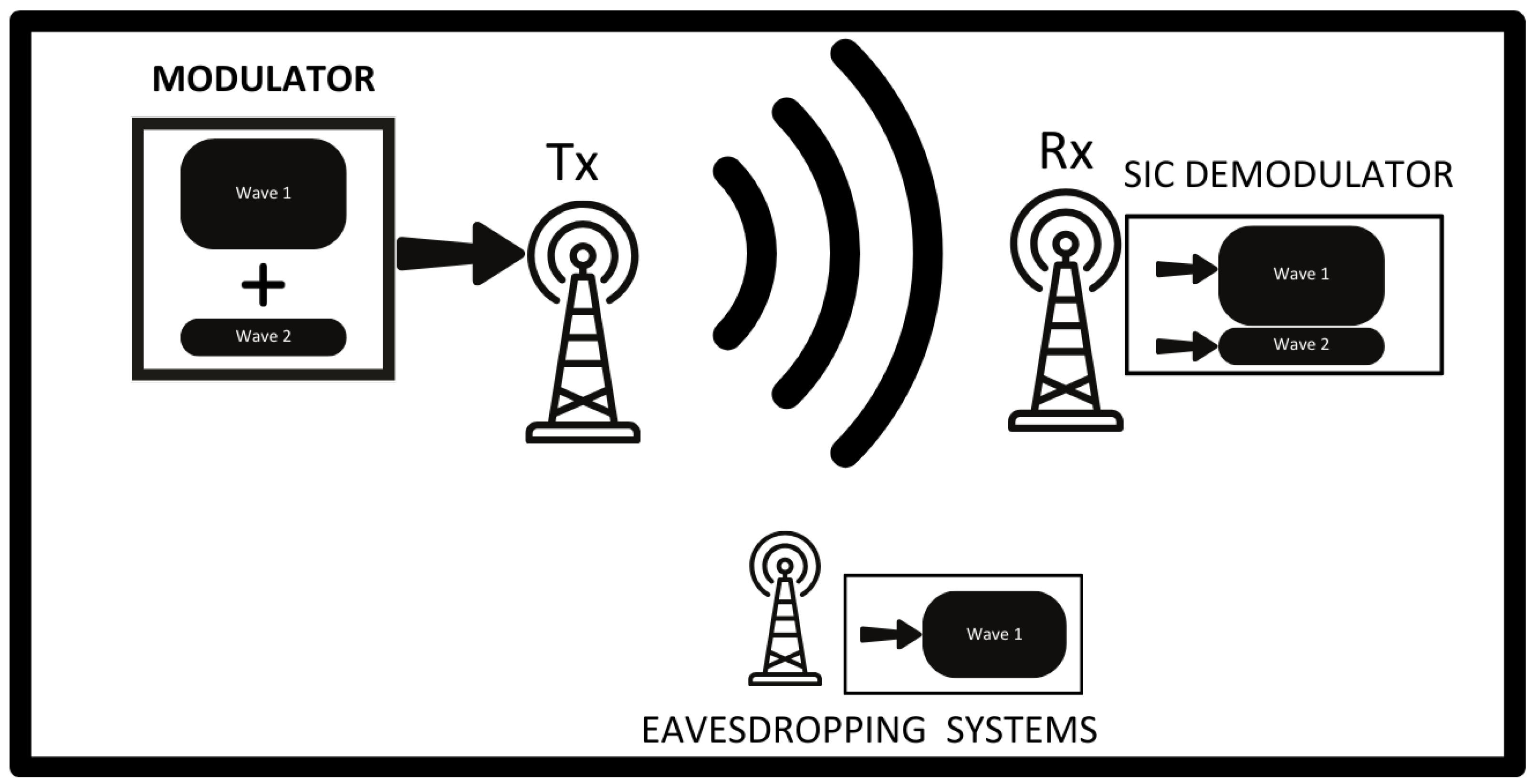
Figure 1 illustrates the system overview. The HF band has limited bandwidth; according to the transmitter properties, this experiment uses only 8 kHz occupied bandwidth. The experiment parameters are summarized in
Table 1.
Let
N be the number of subcarriers. The OFDM symbol vectors for the high-power and low-power layers are
with power allocation coefficients
satisfying
and
[
8,
13,
14].
Table 1.
OFDM waveform parameters for the experiment.
Table 1.
OFDM waveform parameters for the experiment.
| Parameter | Value |
|---|
| Guard Interval Rate | 1/16 |
| FFT Size (N-FFT) | 128 |
| PSK Modulation Order | 2 (BPSK) |
| Pilot Tone Placement | |
| Pilot Tone Modulation | BPSK (value fixed ) |
| Carrier Frequency | 28,780 kHz |
Pilot tones are placed on every eighth subcarrier of
, and the same subcarriers are nulled in
:
The transmitted NOMA–OFDM vector is [
15]
The received frequency-domain vector is modeled as
where ∘ denotes the Hadamard (element-wise) product,
is the per-subcarrier channel, and
is AWGN.
Channel estimation and SIC: [6,16] On pilot subcarriers
,
and
is obtained on data subcarriers via linear interpolation between adjacent pilots. Zero-Forcing equalization gives
where ⊘ denotes element-wise division. Since
, we first detect
, reconstruct
, and then cancel to obtain
2.1. Parameter Selection Rationale and Analytical Bounds
This subsection provides the theoretical rationale behind the selected parameters (, FFT size, guard interval, and pilot spacing) and derives bounds that link the deception objective to the reliable reception of the legitimate layer.
2.1.1. PowerAllocation for Deception vs. Reliability
Let the total average symbol power be
P, and define allocation coefficients
with
and
. An
uninformed eavesdropper does not perform SIC; hence the high-power layer acts as structured interference when attempting to decode the low-power layer. Considering
for the pre-allocation SNR, the instantaneous (low-power) SINR at the eavesdropper is
For the
legitimate receiver, SIC removes the high-power layer up to a small residual fraction
that captures channel estimation and symbol decision errors. The post-SIC SINR for the low-power layer becomes
Let
denote the decoder threshold required by the chosen modulation/coding to meet the target BER. Deception requires that the eavesdropper remains
below the threshold while the legitimate receiver stays
above it:
Using (8)–(10) yields a
window for a feasible
(given
):
Feasibility requires
and
to satisfy (
11). In practice,
is small (good SIC), so increasing
widens the deception margin (smaller
) but simultaneously reduces
and therefore the legitimate layer’s robustness. This formalizes the empirical trade-off observed in our measurements.
Design Recipe (Summary)
(i) Fix
for the selected modulation/coding and target BER. (ii) Estimate
from pilot-aided SIC (or set a conservative bound, e.g.,
dB). (iii) Use the expected
and the worst-case
to compute
via (
11). (iv) Choose
and set
.
2.1.2. FFT Size, Subcarrier Spacing, and Guard Interval
With occupied bandwidth
and
, the subcarrier spacing is
We employ a guard interval (cyclic prefix) ratio of
, which yields
The choice
ensures that the linear convolution over the HF channel (maximum excess delay
) is captured as a circular convolution and prevents inter-symbol interference in FFT demodulation. In our campaign, channel sounding using the known preamble confirmed
, thereby validating the
guard interval.
2.1.3. Pilot Placement and Channel Tracking
Pilots are inserted on every eighth subcarrier of the high-power layer and nulled on the low-power layer, i.e., . This yields a frequency pilot spacing of . Given the symbol duration , this density satisfies the usual sampling requirements for piecewise-smooth HF channels: the linear interpolation of between adjacent pilots maintains MMSE within the noise floor for the measured Doppler and delay spreads, while nulling the same tones on the low-power layer minimizes inter-layer pilot contamination and improves SIC initialization.
2.1.4. Link to Reported Operating Points
The two operating points reported in
Section 3 (e.g.,
and
) are consistent with (
11) under the measured SNR range and small SIC residue (
): a larger
strengthens deception (lower
) but tightens the reliability margin of the legitimate layer, matching the trend seen in the BER curves versus SNR and distance.
2.2. System Configuration in High-Frequency Radio
The system consists of a mobile transmitting station and a fixed receiving station.
2.2.1. Transmitting Station
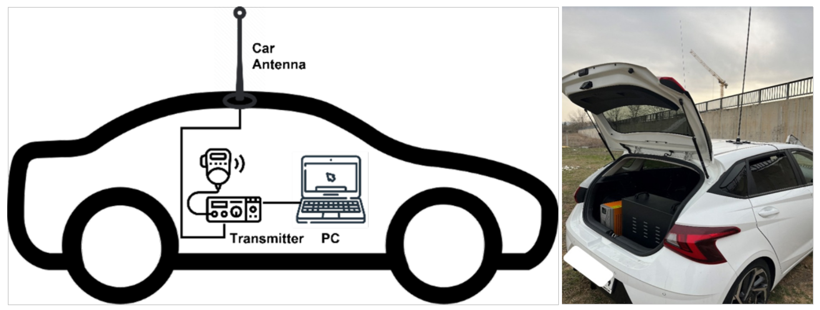
The station includes a computer, a transmitter, and an antenna [
3,
7,
11]. The transmitter and computer are inside a car; the antenna is mounted on the car. The ICOM IC-7300 is used as the transmitter. After scanning the spectrum to find an empty channel, 28,780 kHz is selected. The IC-7300 and the computer are connected via USB; the antenna is connected to the IC-7300 via coax. The transmission station configuration is shown in
Figure 2.
2.2.2. Receiving Station
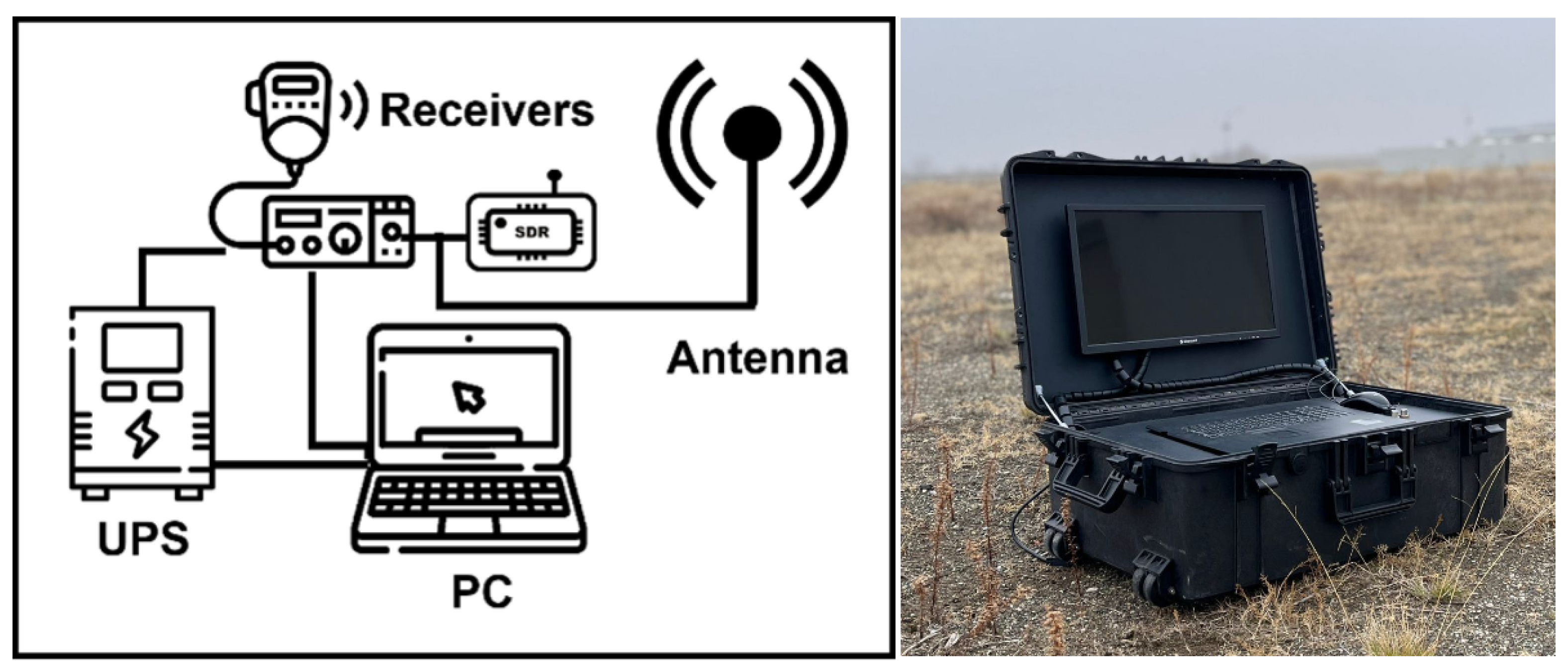
The receiving station consists of an uninterruptible power supply (UPS), computer, receiver (AOR AR-5001D), software-defined radio (SDR), and antenna. The system is constructed in a hangar; the antenna is located outside near the door. Since the hangar had no electricity, a UPS is used. The receiver is tuned to 28,780 kHz. The AR-5001D provides IF output at 45 MHz; therefore an SDR is added to digitize the data and is connected to the computer via USB. The receiving station configuration is shown in
Figure 3. The spectrum and signal at the receiving antenna are shown in
Figure 4 in our decoder’s interface.
2.3. Application
Signals are received for distances of 0.18, 0.30, 0.55, 0.95, 1.7, 3, 5.4, 9.5, 17, and 30 km. The signal received at 5.4 km is shown in
Figure 4. Every transmission is repeated 50 times for each geographic location. Measurements also show that this geographical area exhibits time-invariant channel parameters during the campaign. A known OFDM sequence is transmitted and received at each step for analyzing the channel. A Zero-Forcing equalizer is used at the receiver. The noise floor is approximately
dB, and an analog low-pass filter is used in the device. The distance between the receiver and transmitter is increased stepwise to compute the bit error rate (BER).
Channel Coding and Frame Configuration
In order to evaluate the performance enhancement achievable by forward error correction, convolutional channel coding with rate was introduced into the system. A conventional constraint length convolutional encoder with the generator polynomial set and a Viterbi decoder was employed, following a widely adopted trellis structure in HF modem implementations.
When convolutional coding was applied, the frame structure was adapted accordingly. The uncoded frame contained 128 data bits per layer (plus 8 pilot symbols on each side), resulting in 144 subcarriers per OFDM symbol. After the application of rate- coding, all 64 input bits were encoded into 128 coded bits, preserving the same 144-subcarrier OFDM frame length while maintaining pilot allocation identical to the uncoded configuration.
Both coded and uncoded frames were transmitted under identical propagation conditions (
Figure 5) to directly compare the effect of coding gain on the system’s bit error rate (BER). The same power allocation coefficients,
and
, were used to ensure fair comparison.
3. Results
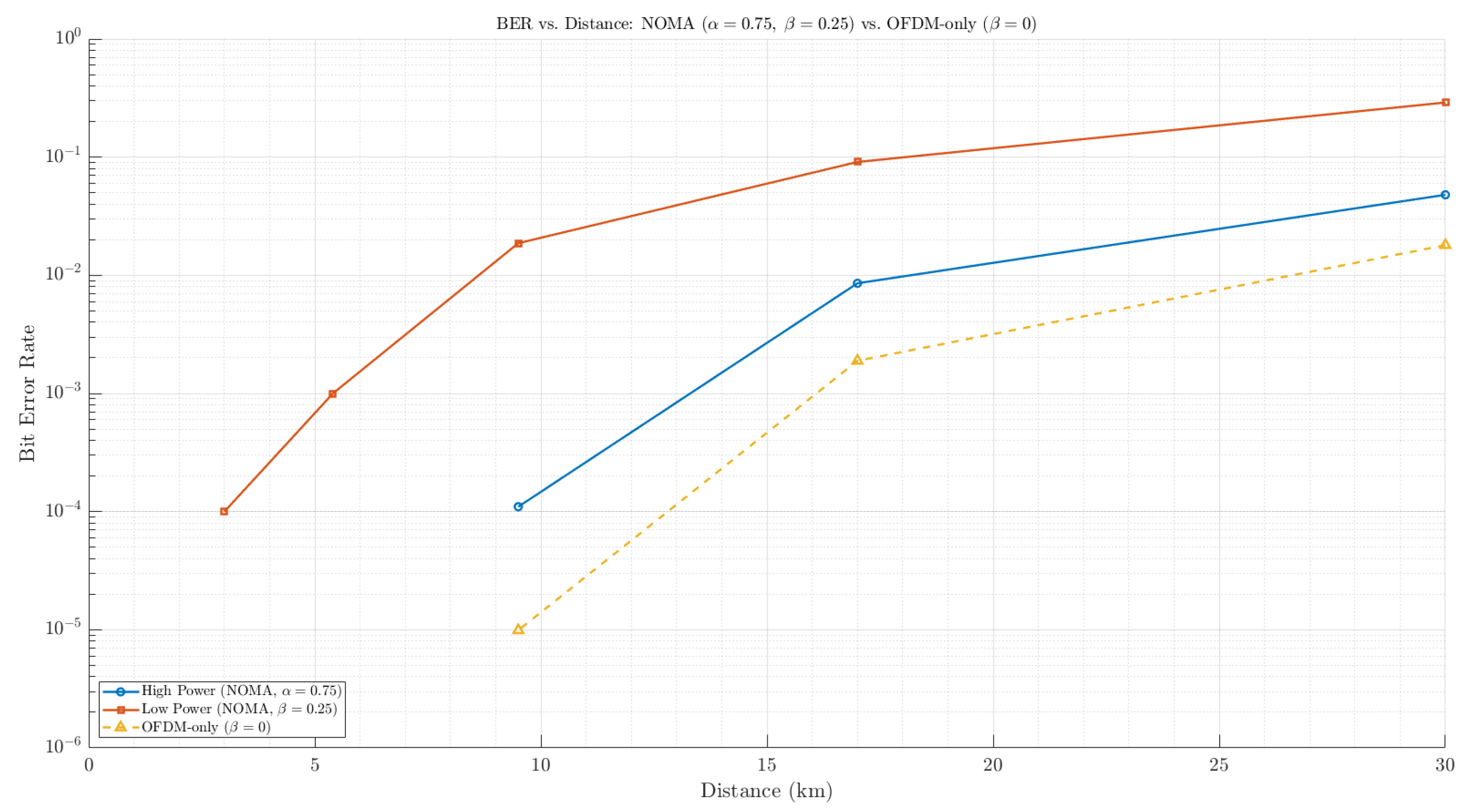
BER performance versus distance (km) is analyzed for Message 1 (high-power, deception) and Message 2 (low-power, legitimate) in
Figure 6. It can be seen that Message 2 can be hidden in this waveform when the transmitter and receiver are closer than 10 km. The selection of
and
is important due to the inter-layer interference between the two scaled waveforms.
In
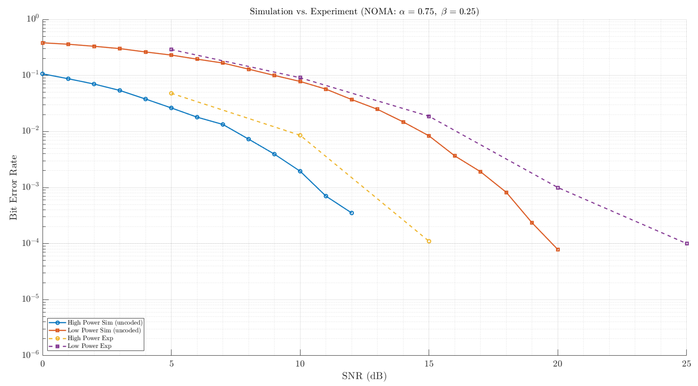
Figure 7, the theoretical and experimental BER performance results are compared for the proposed model. As expected, the high-power deceptive message exhibits a better BER than the low-power legitimate message. According to the results, this system can be used for deceiving eavesdropping systems at SNRs of 15 dB or higher.
Another comparison concerns
and
power allocation. As seen in
Figure 7, there is a trade-off between increasing the power disparity and the correct reception of the legitimate waveform: the more
diverges from
, the more the BER curves separate, improving the deception feature, while the BER of the low-power message is degraded. Depending on receiver conditions, operation in high-SNR regions is preferable.
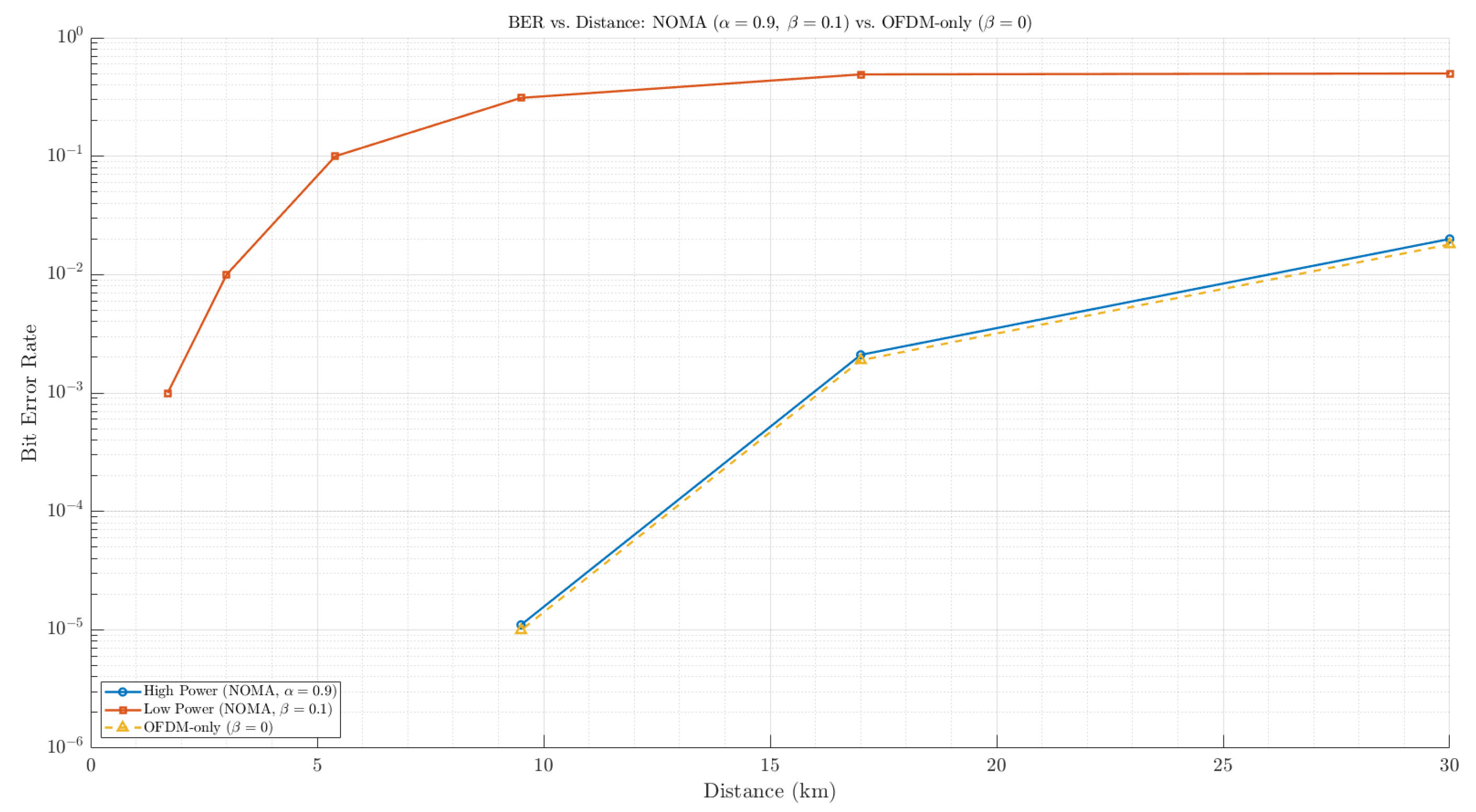
Additionally,
Figure 8 highlights that very small
values may adversely affect integrity even at shorter distances.
For reference, conventional single-layer OFDM-only transmission () was also evaluated. As expected, this configuration achieved a slightly lower BER due to the absence of inter-layer interference, serving as a baseline benchmark for assessing the additional complexity and deceptive advantage introduced by NOMA.
Figure 6.
BER vs. distance (km), where , and , with a comparison of mode (OFDM only).
Figure 6.
BER vs. distance (km), where , and , with a comparison of mode (OFDM only).
Figure 7.
BER vs. SNR, where , and .
Figure 7.
BER vs. SNR, where , and .
Figure 8.
BER vs. distance (km), where , and , with a comparison of mode (OFDM only).
Figure 8.
BER vs. distance (km), where , and , with a comparison of mode (OFDM only).
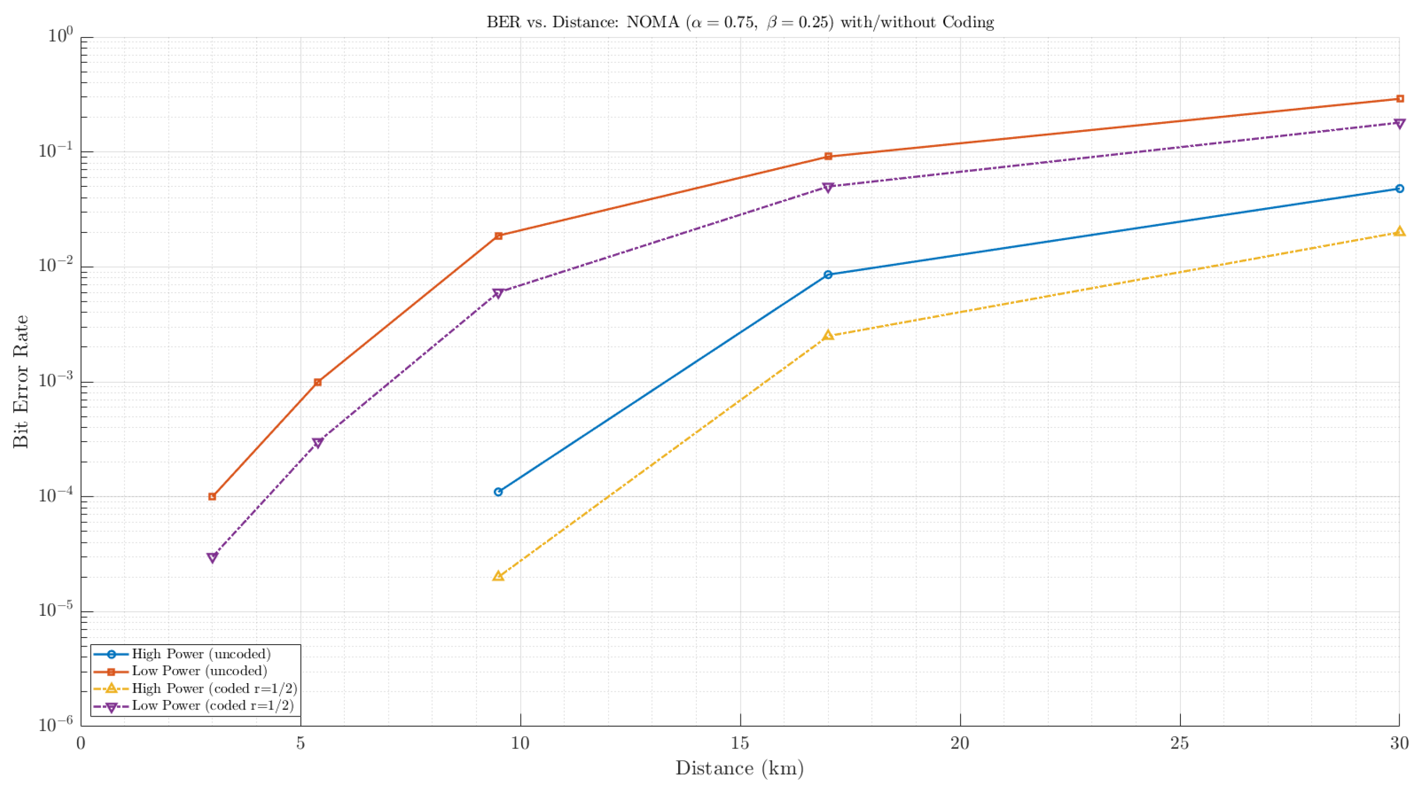
Furthermore, convolutionally coded transmissions were evaluated to quantify the coding gain relative to uncoded cases. As shown in
Figure 9, the rate-
convolutional code provides a significant improvement in the BER, especially for the low-power legitimate message. The coded curves exhibit a reduction of approximately one order of magnitude in the BER at medium-to-high SNR levels. This result confirms that error control coding can effectively extend the reliable range of the legitimate signal without compromising the deceptive characteristics of the high-power layer.
Figure 9.
Bit error rate (BER) versus distance for the proposed NOMA–OFDM link with power split and . The uncoded and rate- convolutionally coded results are shown for both layers; coding notably lowers the BER, especially for the low-power layer at longer ranges. (Log scale; points with measured BER are omitted.)
4. Conclusions
This study investigated the BER performance of dual-message NOMA–OFDM transmission under different power allocation factors, and . We showed that the low-power legitimate message can be effectively hidden within the waveform below 10 km and that increasing power disparity improves deception while degrading the legitimate layer’s BER. Consequently, the choice of and must balance deception strength and reliable communication, depending on the operational SNR and receiver conditions. Overall, the proposed model is practical for deceiving eavesdropping systems, particularly at SNRs of 15 dB or higher. Additionally, by incorporating a rate- convolutional encoder with a trellis, the proposed model demonstrated substantial BER reduction for both layers compared to the uncoded configuration. The coding gain was more pronounced for the low-power layer, improving reliability at longer distances where uncoded transmission suffered from severe errors. These results indicate that combining NOMA-based power-domain superposition with forward error correction offers a practical balance between deception and robustness in HF communications. In comparison, the OFDM-only reference confirmed that the absence of power-domain superposition leads to a marginally improved BER but eliminates the system’s deception capability. Therefore, while OFDM serves as a useful benchmark for validating the performance of the proposed method, the NOMA-based dual-layer structure remains essential for combining spectral efficiency with concealment.
