1. Introduction
The rapid development of electronic information technology, coupled with the increasingly complex environments and the diversified combat missions, has imposed higher requirements on modern radar systems. With the advent of the cognitive radar concept, radar has shifted from traditional receive signal processing paradigms toward a learning-based cognitive framework [
1]. Cognitive radar draws on prior knowledge of targets and interactive learning with the environment to adaptively optimize operating modes, transmit waveform parameters, echo signal processing strategies, and system configurations in complex scenarios. This paradigm enables transmit waveform optimization and intelligent receive processing, thereby enhancing radar performance in the detection, estimation, tracking, classification, and recognition of targets [
2,
3,
4]. By actively adapting the transmitted waveform and even countering external interference while selecting appropriate receive processing strategies, radar system performance can be effectively improved. Therefore, joint transmit–receive adaptive processing has emerged as a critical research direction for the modernization and intelligence of radar systems.
MIMO radar exhibits significant advantages, such as high degrees of freedom, flexible operating modes, enhanced clutter suppression, multi-target tracking, and anti-interference capability. Hence, extensive research has been conducted on MIMO radar signal processing, waveform design, parameter estimation, target localization [
5,
6,
7], and detection performance and estimation accuracy [
8,
9,
10]. In recent years, to fully exploit the waveform diversity offered by colocated MIMO radar [
11], considerable attention has been given to the joint optimization of transmit waveforms and receive filters, particularly in scenarios with signal-dependent interference or clutter, as detailed in [
12,
13,
14,
15,
16,
17,
18,
19,
20,
21,
22,
23,
24].
In practical applications, time-varying complex environments lead to inaccurate prior knowledge of targets, clutter, and interference, thereby posing significant challenges for modern radar in target detection and parameter estimation. Consequently, maximizing the output signal-to-interference-plus-noise ratio (SINR) or signal-to-clutter-plus-noise ratio (SCNR) of the receive filter is a critical objective in waveform and receive filter design. Additionally, to ensure that radar nonlinear power amplifiers operate in or near saturation while avoiding waveform distortion, the constant-modulus waveform constraint [
12,
22] or the peak-to-average ratio (PAR) constraint [
24,
25,
26] is widely adopted. Furthermore, similarity, energy, spectral constraints [
26,
27,
28], correlation properties [
29], and ambiguity function shaping [
14] are also considered to generate waveforms with desirable performance characteristics. Therefore, based on these criteria and constraints, optimization models can be formulated to design transmit waveforms and receive filters that are adaptive to the environment, thereby enhancing radar target detection performance.
However, the joint optimization of transmit waveforms and receive filters is typically formulated as a non-convex fractional programming problem. Existing approaches generally decompose it into two subproblems and employ cyclic iterative methods to solve for the receive filter coefficients and the transmit waveform sequentially. Most existing studies focus primarily on the optimization of waveforms, employing various algorithms to enhance performance under specific constraints. One commonly used method is the semidefinite relaxation (SDR) and randomization approach [
30]. This method employs relaxation to reformulate the original optimization problem as a semidefinite programming problem, which is solved using the CVX toolbox. Then, a randomization technique is applied to decompose the resulting semidefinite matrix, thereby generating a feasible waveform. This SDR-randomization framework has been widely adopted in subsequent research [
12,
13,
14,
15,
16,
17]. Another method is Dinkelbach’s transform [
31], which can convert the fractional problem into a linear form. Building upon this transform, Tang et al. [
22] use power method-like (PML) iterations proposed in [
32,
33] to solve the waveform optimization problem under constant modulus constraints. Although these methods are effective in solving fractional programming problems, they suffer from high computational complexity. Moreover, in scenarios involving inaccurate prior information, the detection performance of these methods degrades significantly.
To improve radar detection performance under uncertain prior information, researchers frequently adopt optimization criteria such as maximizing the worst-case SINR [
13,
14,
21,
25] or the average SINR [
17,
18,
19,
20]. Cui et al. reformulated the waveform design under constant-modulus and similarity constraints as a phase optimization problem, and iteratively updated each coding phase within the maximum block improvement (MBI) framework to ensure convergence [
19]. In contrast, Yu et al. applied a coordinate descent framework to iteratively optimize each waveform sample phase [
21]. The computational complexity of this method scales with the waveform code length, which can significantly degrade real-time performance. Cheng et al. introduced auxiliary variables to reformulate the problem. They applied a primal-dual framework combining the block successive upper-bound minimization method of multipliers (BSUM-M) with the alternating direction method of multipliers, using an active-set method to solve the subproblems [
20]. While this method reduces computational complexity relative to SDR and randomization per iteration, it requires more iterations to converge. In subsequent studies, methods such as the alternating direction penalty method (ADPM) [
18] and the coordinate descent combined with Dinkelbach’s transform (CD-DIN) [
16] have demonstrated robust performance even in the presence of inaccurate prior information. However, the optimized waveforms obtained using these methods no longer maintain subcarrier orthogonality unless a similarity constraint with a small similarity coefficient is imposed. Moreover, these methods overlook the algorithmic complexity associated with receive filter design. Specifically, they vectorize the spatial and temporal dimensions into a single signal for joint processing, resulting in a matrix inversion whose dimension equals the product of the number of receive elements and temporal samples. As a result, the computational complexity increases dramatically, severely reducing efficiency for large arrays or high sampling rates.
While methods like [
16,
18] offer robustness, they suffer from high computational complexity due to large matrix inversions and often compromise subcarrier orthogonality. To overcome these simultaneous limitations, this paper proposes a novel low-complexity joint transmit–receive design strategy to mitigate the impact of signal-dependent clutter and steering vector mismatch. We formulate the optimization model for output SCNR maximization under the constant-modulus waveform constraint and solve it by alternately updating the receive filter and transmit waveform. The receive filter is decomposed into a cascade of a spatial beamformer and a temporal filter, where the former is optimized via convex optimization, and the latter is set as the conjugate of the product between the transmit waveform and the estimated steering vector. This structure reduces the matrix inversion dimension from the full product of receive elements and temporal samples to only the number of receive elements, leading to a significant reduction in computational complexity compared with existing mismatch-robust methods [
16,
17,
18,
19,
20,
21]. Furthermore, an orthogonal frequency division multiplexing linear frequency modulated (OFDM-LFM) waveform is employed as the transmit signal and a non-iterative peak searching method is developed to optimize the initial subcarrier phases. Unlike existing approaches that rely on similarity constraints to preserve waveform characteristics, the proposed method optimizes the initial phases without compromising the orthogonality among subcarriers, thereby maintaining the inherent advantages of MIMO radar in virtual aperture extension, waveform diversity, and spatial resolution. Based on the optimized initial phases, the target azimuth angle and steering vector are corrected, followed by an update of the spatial beamforming filter. Simulation results show that the proposed method achieves stable and near-optimal output SCNR with low computational complexity while preserving subcarrier orthogonality compared with existing methods.
The remainder of the paper is organized as follows:
Section 2 presents the baseband echo signal model for MIMO radar.
Section 3 formulates the joint transmit–receive optimization problem.
Section 4 introduces the proposed peak searching method to solve the formulated problem.
Section 5 provides numerical results evaluating the performance of the proposed algorithm. Finally,
Section 6 concludes the paper.
2. Signal Model of MIMO Radar
We consider a colocated narrowband MIMO radar system consisting of a uniform linear array with
transmit and
receive antenna elements. The inter-element spacing is set to
, where
is the wavelength. Assume each transmit element emits a distinct orthogonal subcarrier, generating a total of
subcarriers. Let
denote the pulse duration. The number of samples per pulse is
, where the sampling frequency
equals the system bandwidth
B, i.e.,
. The transmit data matrix can be expressed as follows:
where the superscript
denotes the transpose.
Consider an orthogonal frequency division multiplexing linear frequency modulated (OFDM-LFM) waveform. The discrete-time baseband signal of the
-th subcarrier at the
k-th sample index can be expressed as follows:
where
is the baseband starting frequency of the -th subcarrier.
denotes the frequency spacing between adjacent subcarriers.
represents the bandwidth of the -th subcarrier.
is the chirp rate (i.e., frequency modulation slope) for the -th subcarrier.
denotes the initial phase of the -th subcarrier.
indicates the discrete-time sample index with K being the total number of samples per pulse.
Under the narrowband assumption, the transmit and receive steering vectors for the direction
can be expressed as follows:
After downconversion, bandpass filtering, analog-to-digital conversion (ADC), and quadrature digital downconversion (DDC) on the received echo signals, the digital baseband echo signal for a far-field point target in direction
can be expressed as follows:
where
is a complex parameter representing the target radar cross section (RCS). The digital baseband target echo signal can be expressed in column vector notation as follows:
where
represents the
identity matrix, ⊗ represents the Kronecker product, and
denotes the column vector obtained by stacking the columns of a matrix.
Let
, then
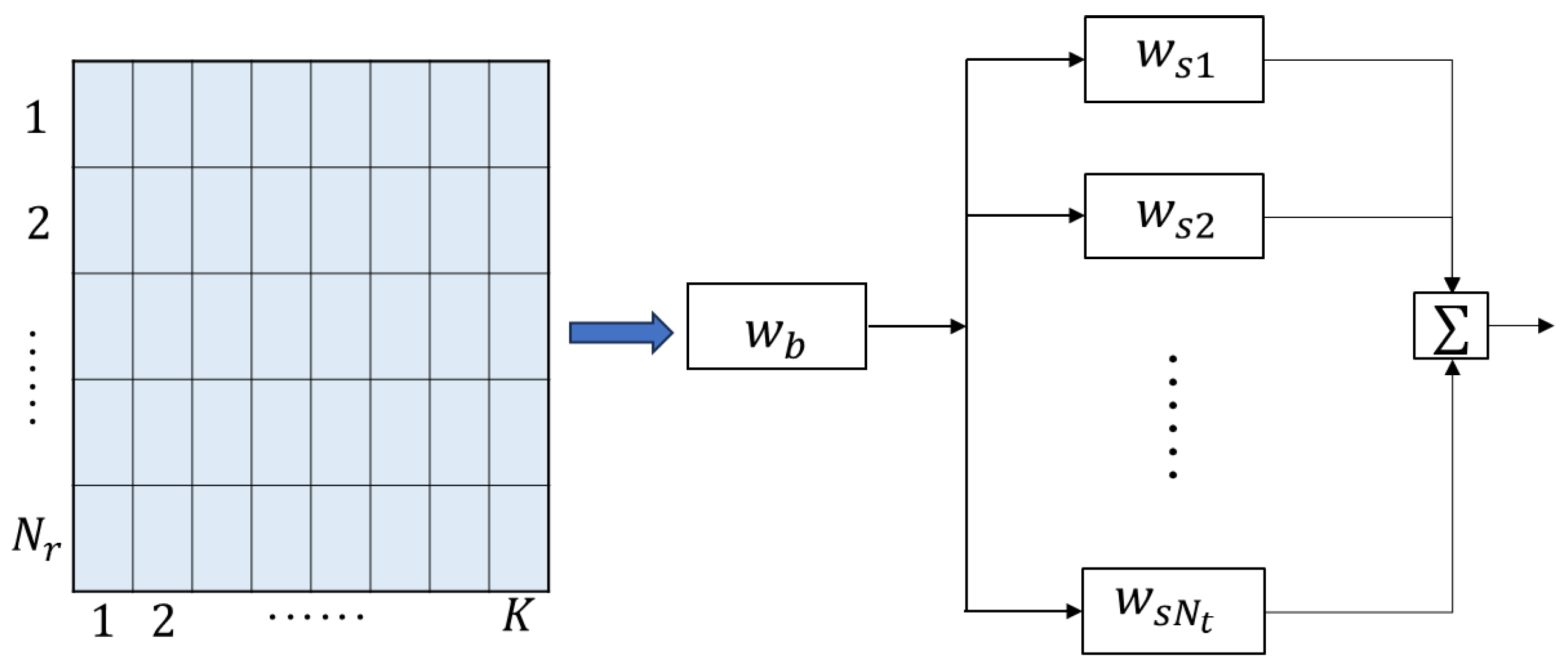
Considering clutter from adjacent range bins with
L independent clutter sources, where the
l-th clutter source has direction
and complex amplitude
. Specifically,
range bins are indexed by
, and the
l-th clutter source is located in range bin
, as shown in
Figure 1a. The clutter is assumed to occupy the same temporal processing window as the target echo signal, as illustrated in
Figure 1b.
Thus, the clutter can be mathematically expressed as
where
is the shift matrix defined as
reformulated in column vector notation:
Define
, where
denotes conjugate transpose. Then,
The overall digital baseband echo signal for
receiving elements can be expressed as follows:
Equation (
12) can be expressed in column vector form:
where
is modeled as an independent and identically distributed (i.i.d.) zero-mean Gaussian white noise with power spectral density
.
4. Joint Design of Waveforms and Filters
In this section, we solve the optimization problem (
23) sequentially, by alternatively updating the receive filter and the transmit waveform.
4.1. Space Filter Design for Fixed Waveforms
For the optimization problem of the spatial filter, the objective function can be simplified to maximizing the output SCNR of the spatial filter, i.e.,
, which can be further transformed into
. Therefore, given the estimated target direction, the optimization model for the spatial filter can be expressed as follows:
The above problem is convex and can be solved using the CVX toolbox [
36,
37].
4.2. Waveform Design for Fixed Filters
When the spatial filter
is determined,
is a constant, denoted as
. Similarly,
is denoted as
. Given the initial waveform
, its initial phase is set to
, where
denotes the zero vector of dimension
.The corresponding temporal filter
can be written as follows:
By substituting these values into Equation (
20), the output SCNR can be expressed as follows:
Under the mismatched condition, where
,
, and
is a shift matrix, the value of
is smaller than
. Moreover, since the spatial filter
is designed to satisfy
(from Equation (
24)), the contribution of the clutter source to the output power is inherently suppressed. This suppressed contribution can be bounded as follows:
Therefore, the output SCNR can be simplified to
Moreover, since , are determined, the output noise power remains constant,
making the maximization of the signal power the dominant factor for improving SCNR in this context.
Similarly, due to the inaccuracy in target direction estimation, i.e.,
, the value of
is smaller than
. Therefore, the initial phase of the waveform is optimized to maximize the output signal power. This optimization process aims to find the set of phases
that maximizes the output SCNR. Specifically, the optimized waveform is given by
, with
. Then,
where
and ⊙denote the conjugate operation and the Hadamard product, respectively, and
denotes a diagonal matrix formed by the entries of a vector argument.
To maximize the value of Equation (
29), denoted as
, the initial phase
of the
-th subcarrier modulation must satisfy the following relationship:
It can be observed from the above relationship that forms an arithmetic sequence. Specifically, for , the initial phase of the -th subcarrier is given by . Therefore, to determine the optimal initial phases of all subcarriers, it suffices to find the optimal phase for the second subcarrier,.
Assuming that the estimation error in the angle is
, where
represents the error interval, which is uniformly sampled over the angle domain. The initial phase
corresponding to the
q-th sampled angle (
) can then be expressed as follows:
With this initial phase, the peak value of the target signal at the output of the receive filter can be expressed as follows:
Here, represents the time-domain filter for the -th subcarrier, which facilitates subcarrier separation and satisfies the following relationship . Equivalently, this can be expressed in matrix form as .
Since the target echo cannot be completely separated from the received signal in practical radar applications, the objective of maximizing the output signal power is further reformulated to maximize the output echo signal power. Accordingly, the optimization model is formulated as follows:
Assuming that the error angle corresponding to the peak value is
, we have
Thus, the optimized waveform can be obtained as follows:
4.3. Correction of Receive Filter Coefficients
Based on the angle
corresponding to the peak value, the coarse estimate of the target azimuth can be corrected as follows:
Thus, the corrected receive steering vector is given by the following:
Using the corrected receive steering vector, the optimization problem
from
Section 4.1 is solved, yielding the corrected spatial filter coefficients
. Then, the final received filter coefficients are obtained as
.
Finally, the peak searching algorithm (PSA) is summarized in Algorithm 1.
| Algorithm 1 PSA for the Joint Waveform s and Receive Filter w Design |
- Input:
,, , (the received signal data matrix containing target, clutter, and noise components), - Output:
Designed waveform and receive filter - 1:
Solve the problem of , get the initial . - 2:
According to ( 25) calculate . - 3:
. - 4:
for do - 5:
Calculate using ( 31). - 6:
Obtain . - 7:
Calculate . - 8:
end for - 9:
Solve the problem , find the peak of , obtain . - 10:
The optimized waveform is obtained as follows. - 11:
Using (36) and (37) to obtain and . - 12:
Update , using the modified receive steering vector, the optimization problem of is solved. Then, obtain the corrected spatial domain filter coefficients . - 13:
Finally, obtain the final coefficients of the receive filter
|
4.4. Algorithm Complexity Analysis
This subsection analyzes the computational complexity of the proposed peak searching algorithm in terms of the number of required multiplications. When solving for
, the CVX-based solver exhibits a computational complexity of
. The optimization of
and the computation of the initial phases
for different angular errors can be implemented using the coordinate rotation digital computer (CORDIC) rotation approach, which only requires shift, addition/subtraction operations, and simple lookup tables, and does not require any hardware multipliers[
38]. The computation of output peaks for different angular errors,
, involves
multiplications, where Q denotes the number of discrete angles used to divide the angular uncertainty interval. It should be noted that the choice of the number of samples Q is a trade-off between estimation accuracy and computational cost. Once the peak location is identified through the peak searching process, the corresponding initial phase is selected, and the target angle is refined to compute the updated receive steering vector, which is again solved using CVX with complexity
. Consequently, the total computational complexity of the proposed algorithm can be expressed as
.
In particular, if the target azimuth angle is perfectly known, only Steps 1, 2, and 13 of the proposed algorithm are needed to achieve a nearly ideal output SCNR, with a computational complexity of .
5. Numerical Simulations
In this section, numerical simulations are conducted to evaluate the proposed peak searching algorithm (PSA) for the joint transmit–receive design problem, and the performance is compared with the sequential optimization algorithm 2 (SOA2) [
12] and the coordinate descent combined with Dinkelbach’s transform (CD-DIN) method [
16]. The default simulation parameters are listed in
Table 1. A uniform linear array with element spacing
is considered, where each element transmits an OFDM-LFM signal.
An arbitrary set of subcarrier bandwidths, less than the subcarrier frequency spacing, is selected to ensure orthogonality of the subcarriers in the frequency domain. Specifically, without loss of generality, is set as MHz. Assume the target is located in the 0-th distance unit with an actual azimuth , a power dB. Additionally, consider clutter from targets near the 0-th range bin. For example, with , the clutter positions in distance units are , and their corresponding angles are , , and , with powers dB, dB, and dB. The noise is modeled as additive white Gaussian noise with zero mean and unit variance, i.e., dB. All the experiments are carried out by using Matlab 2021a on a desktop computer (with Intel(R) Core(TM) i9-10900 CPU and 32 GB RAM).
5.1. Joint Design Under Deterministic Conditions
In this subsection, the assumptions of ideal array elements (i.e., without amplitude and phase perturbations) and an accurately known target position are considered. Notably, the proposed method eliminates the need for iterative optimization cycles;thus, we compare only the final converged output SCNR.
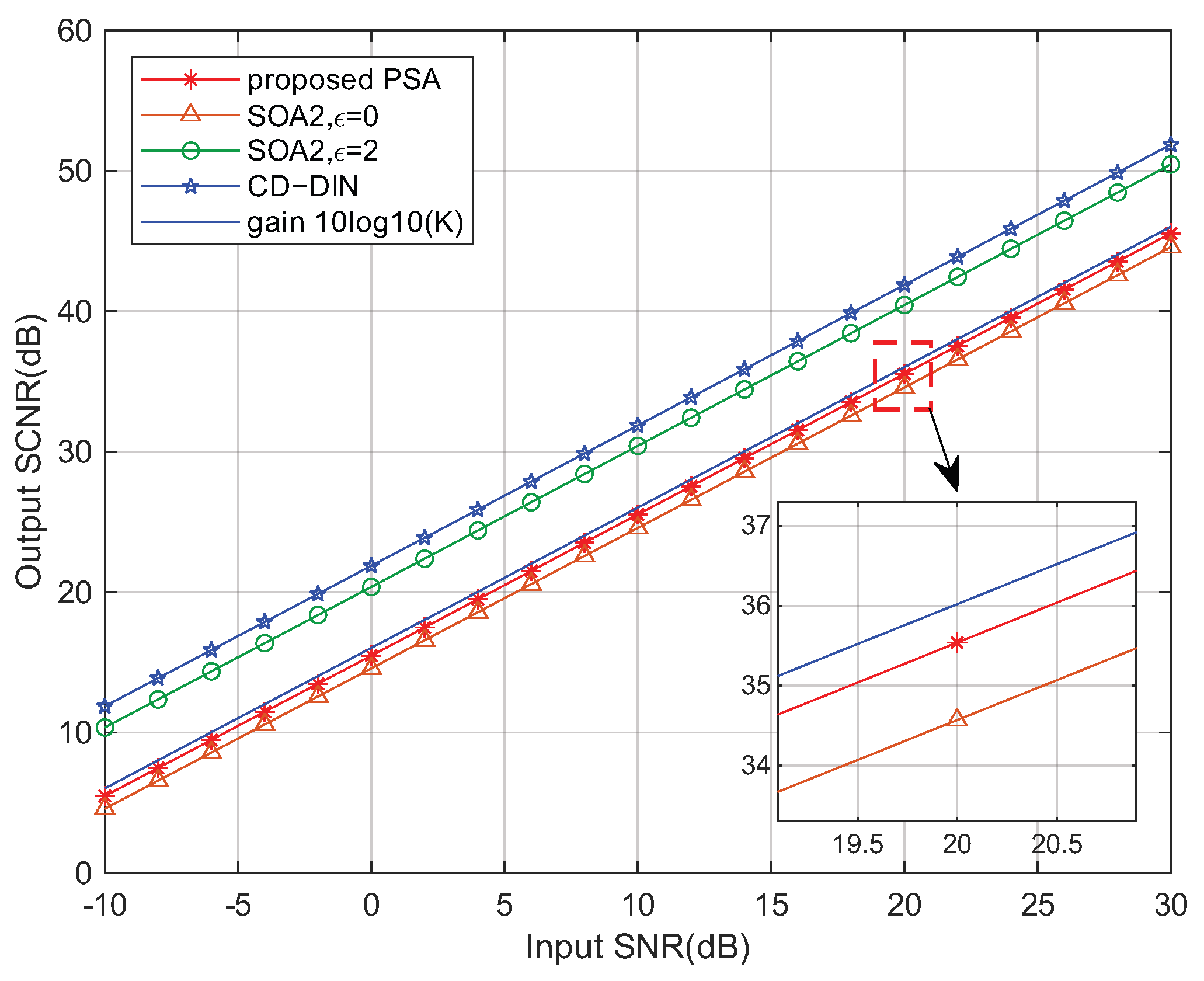
Figure 3 shows the output SCNR performance of the proposed PSA, the SOA2, and the CD-DIN method under varying input SNR conditions.
Figure 3 illustrates that the proposed PSA, as well as the SOA2 and CD-DIN methods maintain stable SCNR improvement across varying input SNR levels. At an input SNR of 20 dB, the proposed method achieves an output SCNR gain of 15.68 dB, approaching the theoretical upper bound of
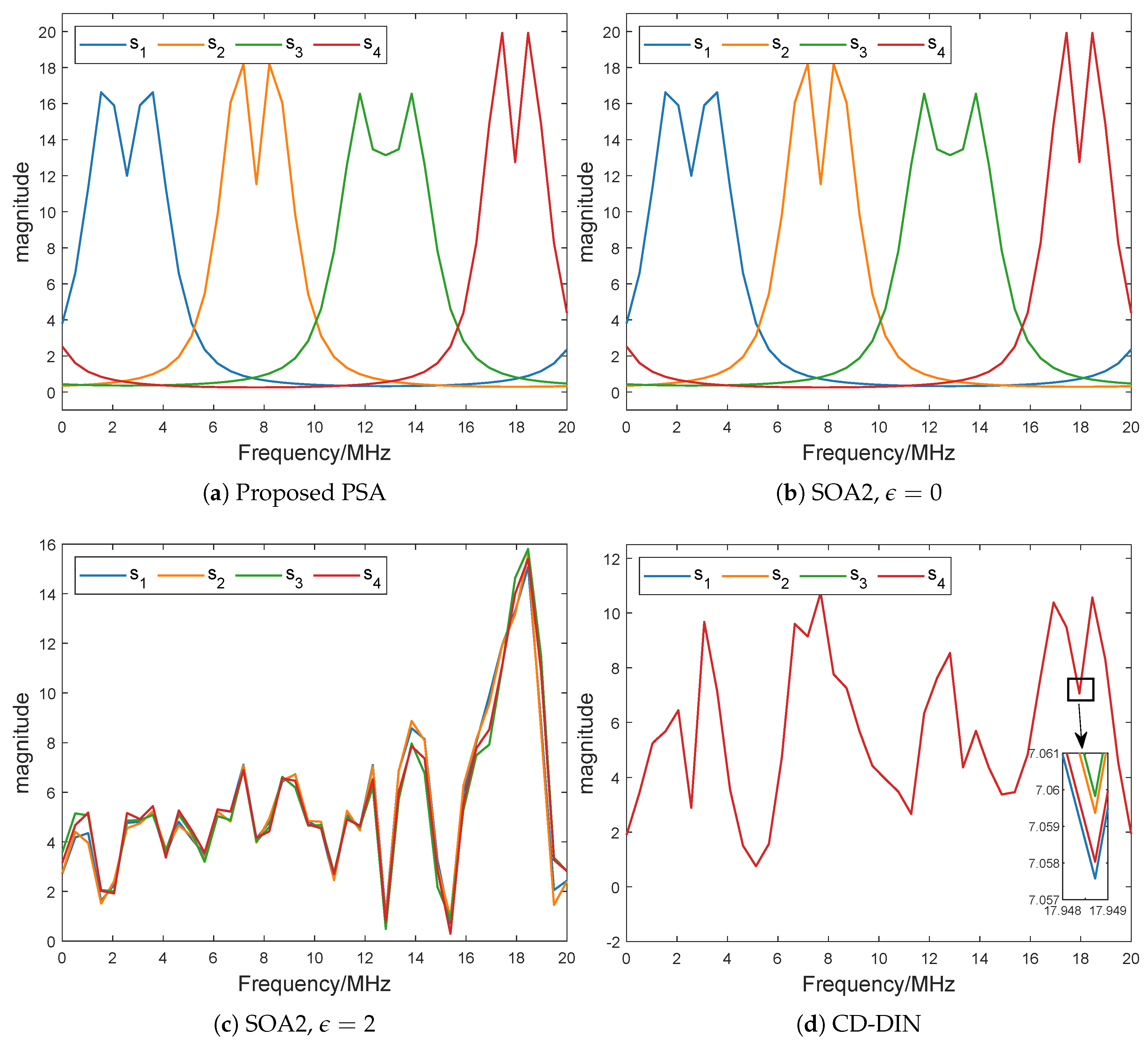
dB. Moreover, as evidenced by
Figure 4a and
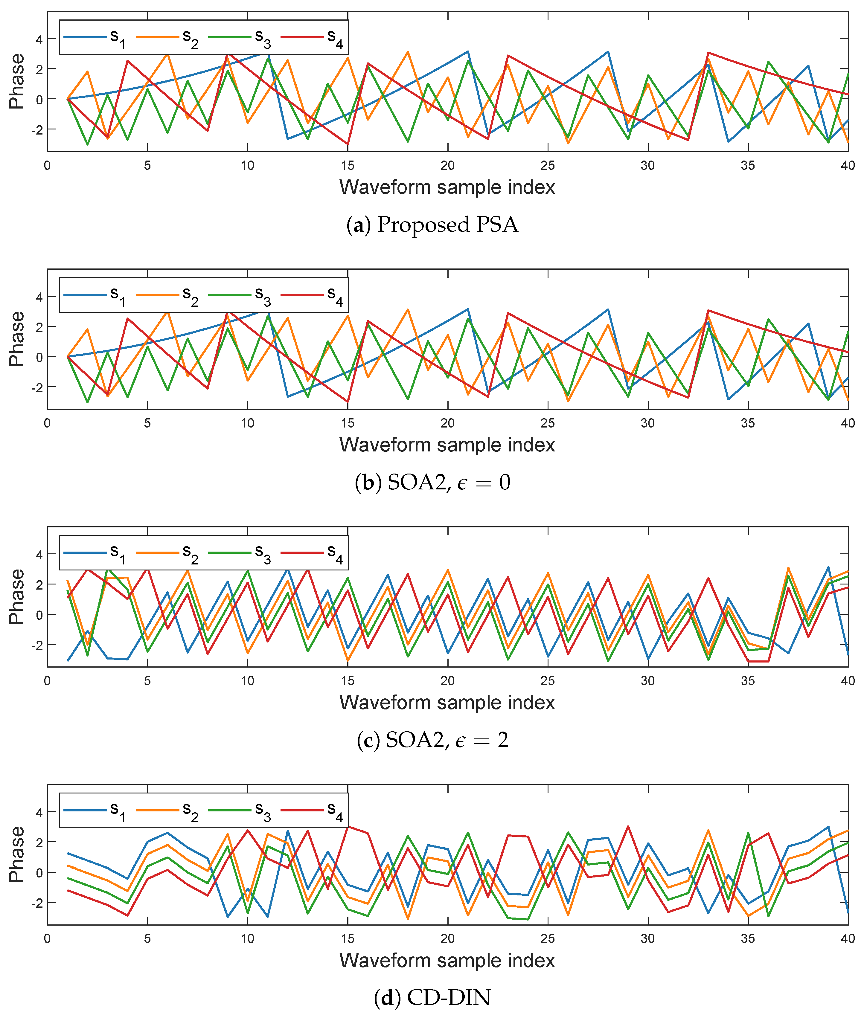
Figure 5a, the optimized subcarriers preserve their orthogonality under the proposed optimization framework. When the similarity parameter
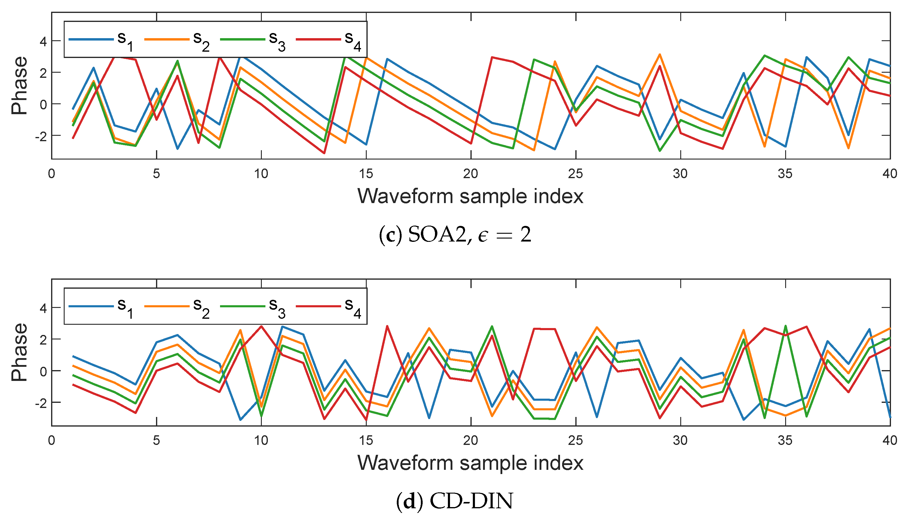
, the SOA2 method effectively reduces to a constant modulus constraint, as does the CD-DIN approach. These methods achieve gains of 21.66 dB and 21.94 dB, respectively, precisely because their optimized waveforms sacrifice subcarrier orthogonality. As shown in
Figure 4c,d and
Figure 5c,d, the optimized subcarrier spectra exhibit nearly overlapping characteristics with similar phase variations. This transformation makes each array element’s transmitted subcarriers into coherent or quasi-coherent signals, thereby boosting the output SCNR by
times. Consequently, the SCNR gain approaches the theoretical limit of
dB.
However, for the SOA2 method, when
, the designed waveform is identical to the reference waveform. As shown in
Figure 4b and
Figure 5b, both methods maintain waveform orthogonality, consistent with our proposed approach. While the SOA2 method achieves a marginally higher gain of 16.02 dB (a 0.34 dB improvement over our method), it suffers from significantly higher computational complexity. In this scenario, compared with the other two methods, our approach significantly reduces the computational complexity per iteration, as shown in
Table 2 where
L represents the number of randomization trials.
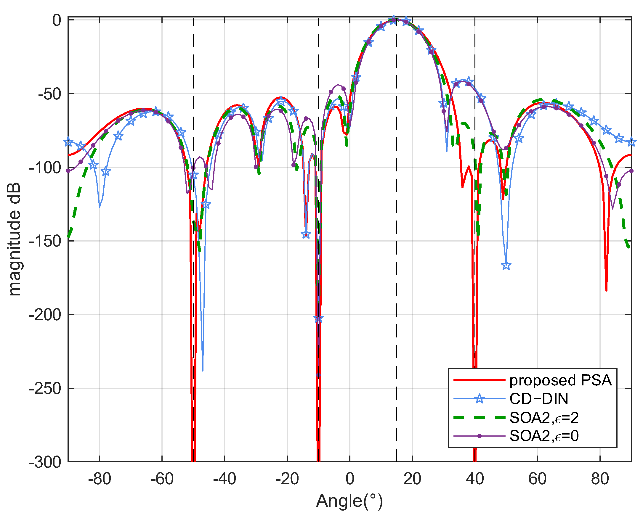
Figure 6 depicts the beampatterns of the proposed PSA, SOA2, and CD-DIN methods. The beampattern
is computed as
where
and
denote the optimized receive filter coefficients and transmitted waveform, respectively. As evident from
Figure 6, all three methods—the proposed PSA, SOA2 and CD-DIN—demonstrate effective clutter suppression capabilities. However, the proposed PSA method achieves superior performance with deeper nulls and lower sidelobes compared to both SOA2 and CD-DIN approaches.
5.2. Joint Design Under Steering Vector Mismatch Conditions
In practical engineering applications, array element amplitude and phase perturbations, as well as inaccurate target angle estimation, may lead to steering vector mismatches and consequently degrade the output SCNR. In this subsection, we model the array imperfections as follows: (1) amplitude errors following a zero-mean Gaussian distribution with variance 0.01; and (2) phase errors distributed as . The coarse target angle estimate is , with an uncertainty interval .
Figure 7 presents the output peaks
evaluated at
increments across the angular uncertainty range. The results identify the maximum peak at
, yielding a corrected target angle
, which better approximates the true target azimuth.
Figure 8 shows the output SCNR loss (measured relative to the ideal case with zero angle estimation error) versus the initial pointing error
. The proposed PSA method maintains excellent robustness, with SCNR loss below 0.01 dB even for large errors, whereas SOA2 exhibits noticeable degradation, which demonstrates the superior correction capability of our approach.
As observed from
Figure 9 and
Figure 10, the waveforms optimized by the CD-DIN method and the SOA2 (
) method lose their orthogonality after optimization, despite originally being orthogonal. This explains why their output SCNRs are higher than that of the proposed method. To further verify this observation,
Figure 11 compares the output SCNR performance of the proposed PSA and SOA2 and CD-DIN methods under practical imperfections, including array amplitude and phase perturbations and target angle estimation errors, across varying input SNR levels. As discussed in
Section 5.1, the slightly lower SCNR of the proposed PSA, compared with the SOA2 (
) and CD-DIN methods, results from the fact that these methods no longer maintain subcarrier orthogonality, thus behaving more like phased-array schemes that can yield higher SCNR. In contrast, the PSA preserves the orthogonal waveform property of MIMO radar, which ensures the advantages of enhanced spatial resolution and multi-target detection capability. Furthermore, when comparisons are made under the constraint of preserving subcarrier orthogonality, the PSA outperforms SOA2 (
), which suffers a 1.45 dB SCNR degradation. As shown in
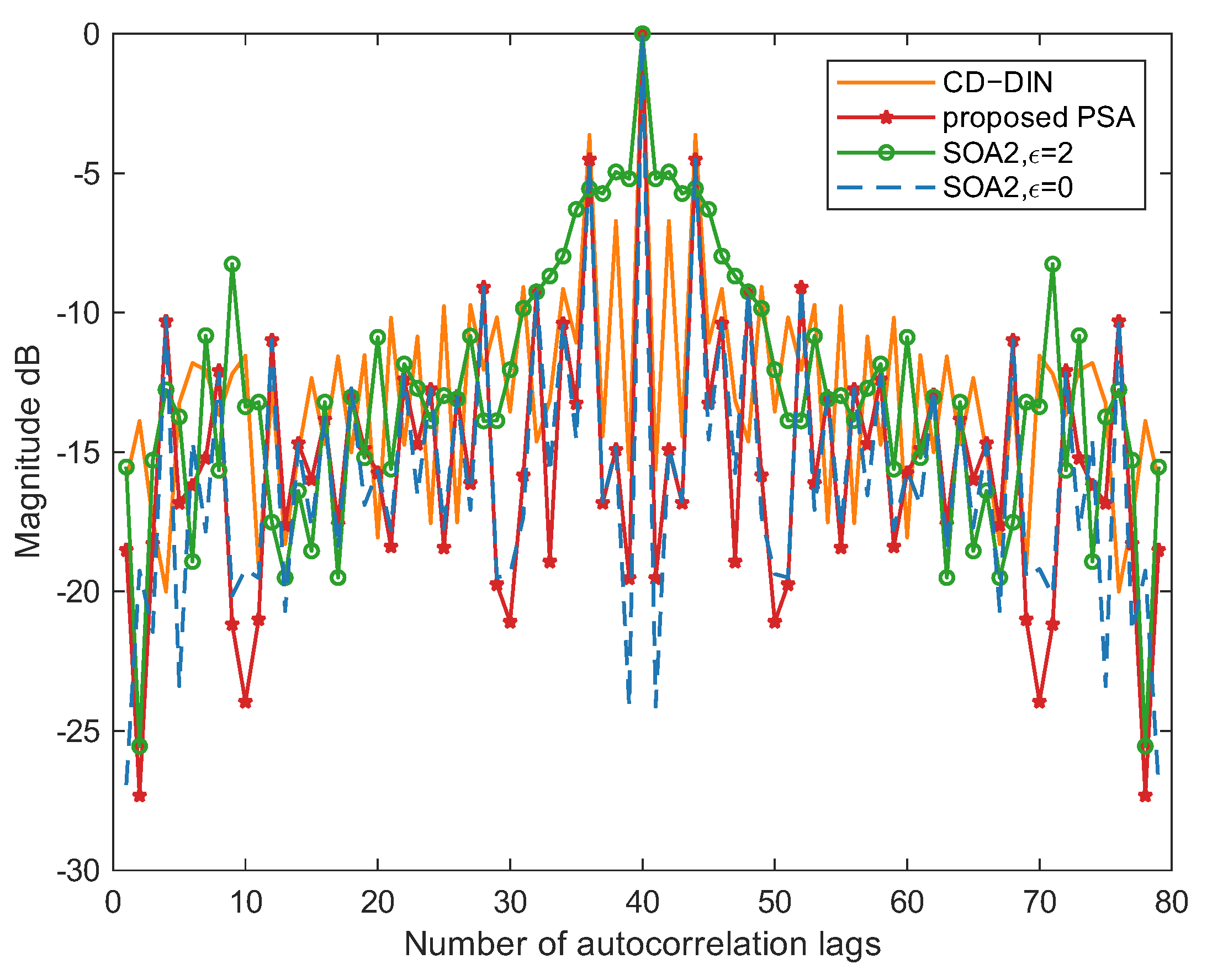
Figure 12, the optimized waveform obtained by the proposed method exhibits superior autocorrelation performance, with a narrower main lobe and lower sidelobes compared to the SOA2 (
) and CD-DIN methods.
Figure 13 compares the beampatterns of SOA2, CDDIN, and the proposed PSA method under steering vector mismatch conditions. The results demonstrate that the PSA method maintains excellent clutter suppression capability while accurately peaking at the true target azimuth. Compared to SOA2, PSA achieves more precise target localization, and relative to CDDIN, it exhibits superior performance with lower sidelobes and deeper nulls.
The algorithmic complexities of these methods are summarized in
Table 3, where
L represents the number of randomization trials. As shown, the proposed PSA exhibits a significantly lower per-iteration computational complexity compared with the other two methods.
6. Conclusions
In this paper, we have investigated the joint design of transmit waveforms and receive filters for MIMO radar systems with signal-dependent clutter plus white Gaussian noise. Since array element amplitude and phase perturbations, as well as inaccurate target angle estimation, may lead to steering vector mismatches and degrade the output SCNR, we propose a low-complexity peak searching strategy under the constant-modulus waveform constraints to optimize the initial phases of the transmit subcarriers, followed by a correction of the estimated target angle and steering vector. Furthermore, the receive filter is decomposed into a cascade of a spatial beamformer and a temporal filter, which reduces the dimensionality of matrix inversion and lowers the computational complexity from to . This decomposition allows for efficient real-time implementation even with large antenna arrays or long waveform sequences. Numerical simulations are provided to validate the performance of the proposed approach. The results reveal the following: (1) The proposed method attains near-ideal output SCNR with substantially lower computational complexity. In the ideal scenario, the SCNR performance remains within 0.34 dB of the theoretical upper bound, while under array element amplitude and phase perturbations, it is within 0.48 dB of the upper bound. Moreover, the proposed method exhibits excellent robustness, with the output SCNR fluctuating by no more than 0.01 dB even as the target azimuth estimation error increases. (2) The proposed method enables rapid and real-time acquisition of more accurate target azimuth angles, with its performance depending on the discretization of the angular uncertainty interval . In practice, the number of samples Q should be carefully selected to balance estimation accuracy and computational cost. (3) The proposed method preserves essential characteristics of the initial waveform without imposing similarity constraints while maintaining subcarrier orthogonality. (4) The proposed method exhibits excellent clutter suppression performance, with null depths reaching −300 dB in the clutter directions, as well as desirable autocorrelation characteristics, with the first sidelobe level reaching −15 dB. Overall, the proposed method achieves a favorable balance between near-optimal SCNR, low computational complexity, and the preservation of waveform orthogonality, which is often lost in other robust methods.
Future research will further investigate optimization design under more practical constraints, such as energy allocation [
39], peak sidelobe level, and integrated sidelobe level [
29]. The proposed approach will also be extended to multi-pulse and wideband MIMO radar systems, while accounting for scenarios with more severe non-Gaussian array errors.

