Article

Zone-Based Simplification of Fuzzy Logic Controllers for Switched Reluctance Motor Drives

by
Abbas Uğurenver
* and
Ahmed Ibrahim Khudhur Khudhur
Department of Electrical and Electronics Engineering, Faculty of Engineering, Istanbul Aydın University, Istanbul 34295, Turkey
*
Author to whom correspondence should be addressed.
Electronics 2025, 14(21), 4248; https://doi.org/10.3390/electronics14214248
Submission received: 6 October 2025 / Revised: 24 October 2025 / Accepted: 28 October 2025 / Published: 30 October 2025

Abstract

In the context of fuzzy logic speed control for switching reluctance motor (SRM) applications, the objective of this work is to propose a unique zone-based simplification technique. Using the procedure that has been outlined, it is made easier to reduce membership functions as well as rule sets in a logical manner. This is accomplished by splitting the error–change-of-error plane into discrete decision zones. This method is separate from heuristic or adaptive reduction strategies since it employs a systematic framework that reduces the number of rules from 49 in the standard design to 9 and 5 without compromising the accuracy of the control. This is accomplished without adversely affecting the performance of the control. The simplified controller that was produced as a consequence of this study decreases the amount of overshoot, enhances the speed at which a dynamic response happens, and makes it simpler to use on digital platforms that are affordable. All of these capabilities were achieved by the controller. Based on simulations and testing carried out in the real world, it has been determined that the zone-based simplified fuzzy controller that was proposed has a superior performance to traditional PID and full-rule fuzzy systems in terms of reaction time, stability, and energy efficiency. Taking all of this into consideration, it is evident that it has the potential to be useful in real-world applications for SRM drives that demand a high level of speed while maintaining a low cost factor.

1. Introduction

Switched reluctance motor (SRM) drives have drawn growing attention for modern high-performance applications, largely owing to improvements in power electronics and control hardware. Their simple construction, mechanical strength, and high torque-to-inertia ratio make them attractive for demanding systems. Because of their fault tolerance and dependable operation, SRMs are now widely used in electric vehicles, renewable-energy converters, and industrial servo mechanisms, where reliable performance over a wide speed range is essential [1,2].
Even with these advantages, achieving smooth and efficient operation in SRM drives remains a difficult task. Maintaining low torque ripple, fast dynamic response, and good steady-state accuracy under changing load and speed conditions is particularly challenging [3]. These problems are mainly linked to the machine’s nonlinear magnetic behavior and the strong coupling between rotor position, torque, and flux linkage [4,5]. Moreover, copper, core, and switching losses continue to affect efficiency, and minimizing these losses under nonlinear operating conditions is an active area of investigation.
Several different control techniques have been investigated in order to find a solution to these shortcomings. While traditional proportional–integral–derivative (PID) controllers are able to function dependably within linear and well-defined working areas, they have a tendency to lose their efficiency when the system displays nonlinearities or when there are fluctuations in the parameters. Fuzzy logic controllers (FLCs), artificial neural networks (ANNs), and evolutionary algorithms are some examples of intelligent and adaptable systems that have been created as a solution to the challenge of imitating human thinking and decision-making under uncertain settings. Among these approaches, FLCs are highly regarded due to the fact that they take advantage of heuristic rule-based logic rather than a comprehensive mathematical model, which enables them to provide a kind of control that is both flexible and reliable [6].
Recent research has highlighted the benefits of simplified fuzzy logic control (SFLC), which minimizes the quantity of membership functions and control rules while preserving similar performance levels. This reduction decreases processing requirements, lowers hardware expenses, and enables real-time use in motor drive systems without compromising accuracy or dependability [7,8]. Hybrid PID–fuzzy supervisory controllers, by integrating the structural simplicity of PID control with the flexibility of fuzzy logic, have exhibited enhanced transient responsiveness and steady-state stability in electric motors. Furthermore, SFLC-based techniques improve the efficiency, durability, and cost-effectiveness of SRM drives, resulting in reduced torque ripple and stable performance under diverse operating situations [9,10].
Following the advent of AI-driven control methodologies, researchers have advanced the creation of intelligent and adaptive control systems, including fuzzy logic controllers (FLCs), artificial neural networks (ANNs), adaptive neuro-fuzzy inference systems (ANFIS), and sliding mode controllers (SMCs) [11,12]. These well-devised solutions can replicate how humans make decisions and navigate uncertainty without requiring an exact mathematical model. Controllers utilizing ANFIS and ANN have exceptional learning capabilities, yet they necessitate substantial training data and may lack reliability. Similarly, hybrid controllers like fuzzy–PID or fuzzy–SMC designs have been suggested to attain a compromise between robustness and flexibility [13]. These hybrid systems present several challenges, the most notable being their complex tuning requirements and high operational costs which render real-time use unfeasible.
A unique zone-based simplification mechanism is suggested in this work to simplify the fuzzy rule basis for SRM speed control. A key difference between the proposed technique and traditional heuristic or adaptive reduction tactics is that it systematically divides the error–Δerror plane into several behavioral zones, each of which is assigned a dominant fuzzy rule. This method drastically reduces the amount of time spent on computing tasks while maintaining short-term control accuracy and performance. The result was a 5-rule FLC that was far easier to implement and had identical dynamic behavior to the complete 49-rule system, but at a fraction of the expense. Embedded and real-time SRM drives benefit from its performance.
The error (e) and change-in-error (Δe) signals are normalized before the fuzzification procedure. This is achieved by utilizing scaling gains Ge and GΔe to transform their physical ranges into the normalized domain, represented by the interval [−1, 1]. Another purpose of GΔu is to deformalize the controller output (Δu) to restore it within the actual control range of the actuator. The normalization method guarantees consistent fuzzy inference across all operational points and mitigates rule saturation during substantial modifications. It also guarantees that fuzzy inference remains consistently distinct. To attain the ideal equilibrium of sensitivity and stability, the scaling parameters were adjusted based on the specified speed and torque attributes of the SRM.
All simulations were executed in MATLAB/Simulink 2024a utilizing a discrete-time solver with a fixed time step of 1 × 10⁻⁶ s. The Mamdani fuzzy inference technique utilizing triangular membership functions and centroid defuzzification was selected for its simplicity and smooth output. The specifications of the SRM model were obtained from a 6/4-pole prototype, and its dynamic performance was evaluated at low, medium, and high speeds. Overshoot, settling time, and steady-state error were employed to assess the transient and steady-state properties of the proposed controller.
This paper introduces a zone-based fuzzy simplification method that reduces the rule base while maintaining SRM drive control accuracy and dynamic responsiveness. Unlike typical reduction or clustering procedures, the recommended methodology provides a control-oriented interpretation of each motor action decision zone, improving transparency and robustness. Extensive MATLAB/Simulink simulations show that the simplified controller performs similarly to the fuzzy system but requires much less processing and is more applicable to real-time settings.

2. Mathematical Modeling of SRM

The torque produced in a switched reluctance motor (SRM) results from the push–pull interaction of reluctance forces. The fluctuation in machine coemerge determines the generated electromagnetic torque, excitation current, rotor position, flux linkage, and cross-sectional profile of a four-phase 8/6-pole switching reluctance motor (SRM). For elucidation, see [14]. Figure 1a,b depict the associated circuit of a single-phase winding. The magnetic properties and operational behavior are intricately linked, resulting in a close coupling and nonlinearity among flux linkage, inductance, and torque. A resistance R in series with an inductance L(i,θ) is contingent upon rotor position θ and stimulation affects the coemerge variation. The modification of rotor position and phase current i thereby illustrates the comparable circuit. The phase voltage can be obtained from Figure 1b [15].
Figure 1. (a) Cross-sectional measurement and (b) a comparable circuit for an 8/6-pole SRM.
Electronics 14 04248 g001
v t = R . i t + d λ i , θ d t
with
λ i , θ = L i , θ i
where λ is the flux connection, contingent upon i and θ . υ ( t ), i t , and L i , θ denote the instantaneous voltage across the excited phase winding, the excitation current, and the self-inductance, respectively. The dynamic behavior of the m-phase SRM can be represented as per Equations (1) and (2) by
v k = j = 1 m { ( R k + ω L k j θ ) i j + ( L k j + i j + i j L k j i j ) d i j d t } ,   k = 1 , 2 ,   …… , m
where ω signifies the rotor angular velocity and m indicates the phase number. The resultant coemerge pertains to the region enclosed by the λ − i curve throughout a singular excitation cycle and can be calculated as follows:
W c e i , θ = 0 i λ i , θ d i
By differentiating the coemerge W c e with respect to the rotor position θ , one can readily obtain the induced electromagnetic torque for a specified current.
T e i , θ = W c e i , θ θ
We define an incomplete torque function as
T k = 1 2 j = 1 m s g n k , j i j d L k j d θ ,                                   k = 1 , 2 , . . , m  
where
s g n k , j = 1 ,   i f   k = j 1 , i f   k j .
The fully electromagnetic torque, incorporating mutual inductance, can be derived from Equations (2) and (4)–(7).
T e = k = 1 m i k T k .
The rotor’s mechanical torque can be articulated as
T m e c = T e B ω J d ω d t
where the mechanical torque (Tmec), the moment of inertia (J), and the friction coefficient (B) are the relevant variables. As shown below, Equation (10) represents the matrix-form behavior model of the SRM that incorporates the magnetic coupling effect, in conjunction with Equations (3), (6), (8), and (9). Given negligible mutual inductance, the following can be stated:
L k j   =   0 ,   i f   k j L k j     0 ,   i f   k = j .
ν 1 ν 2   ν m T m e c = R 1 + ω L 11 θ ω L 12 θ ω L 1 m θ 0 ω L 21 θ R 1 + ω L 22 θ ω L 2 m θ 0   ω L m 1 θ ω L m 2 θ ω L m m θ 0 T 1 T 2 T m B i 1 i 2 i m ω +   L 11 + i 1 L 11 i 1 L 12 + i 2 L 12 i 2 L 1 m + i m L 1 m i m 0 ( L 21 + i 1 L 21 i 1 ) ( L 22 + i 2 L 22 i 2 ) ( L 2 m + i m L 2 m i m ) 0   ( L m 1 + i 1 L m 1 i 1 ) ( L m 2 + i 2 L m 2 i 2 ) L m m + i m L m m i m 0 0 0 0 J d d t i 1 i 2 i m ω

3. Speed Controller Design

In this study, a PID controller and a fuzzy logic controller with different numbers of rules will be presented.

3.1. Speed Regulation of a Switched Reluctance Motor with a Proportional–Integral–Derivative Controller

A doubly salient, singly triggered switched reluctance motor (SRM) generates electromagnetic torque by changing reluctance. The stator has windings while the rotor does not, but both have poles. SRM stator windings are coiled field coils like DC motors. The rotor lacks coils and magnets due to its malleable magnetic material. Magnetic reluctance occurs when the stator and rotor magnetic poles align during stimulation. An electrical control system alternates stator windings to keep the series spinning. Figure 2 shows the SRM’s control architecture block design. For the error detector to take a reading, the rotor position sensor must locate the rotor. The error detector sends an error signal to the controller block after comparing reference and actual speeds. The PID controller controls the converter using this error signal. The converter regulates engine speed by increasing wind.
The regulated variable in the proportional controller is defined by the disparity between the set point and the measured variable. A substantial gain is necessary to enhance the steady-state error. However, if the relative advantage is substantial, the system is deemed unstable. A low gain results in a stable system. A proportional controller reduces error but does not eliminate it. To eliminate steady-state error and enhance response speed, proportional and integral components are combined. PID controller performance is improved by feedback to the converter. The controller may eliminate forced oscillation and steady-state inaccuracy. However, incorporating an integral mode adversely affects speed and stability. The derivative mode may facilitate identification of this issue, predict errors, and diminish response time. The Ziegler–Nichols tuning method is employed to calibrate the PID controller.

3.2. Speed Regulation of a Switched Reluctance Motor with a Fuzzy Logic Controller

This work proposes a zone-based simplification strategy to optimize fuzzy logic controller (FLC) design without losing efficacy. The major goal is to retain the Mamdani-type fuzzy logic controller’s control accuracy and flexibility while reducing the computing load of huge rule bases. In motor drive applications like SRM, PMSM, and DC drives, fuzzy rules rise exponentially with membership functions. The controller typically uses two input variables (error (e) and change in error (Δe)) and one output variable. The standard technique uses 7 membership functions for each input, resulting in a 49-rule matrix (7 × 7); the recommended reduction reduces this to 9 rules (3 × 3). The zone-based technique reduces error by dividing the error–Δerror plane into several behavioral zones, each representing a specific dynamic response trend. Only the dominant rule that best characterizes control action is kept in each region, decreasing duplication without compromising control efficacy. The Mamdani and Takagi–Sugeno approaches are well regarded [16,17,18]. FLCs with Mamdani or Takagi–Sugeno fuzzy inference systems are increasingly used in motor drives, power electronic converters, and power systems. Two-dimensional membership functions characterize fuzzy logic theories as type-1 fuzzy sets [19]. Ref. [20] proposed type-2 fuzzy sets with three-dimensional membership functions as an extension of type-1 fuzzy sets. These sets are ideal for motor drive systems with approximate membership functions. Despite their benefits, type-2 sets are too computationally intensive for cost-sensitive real-time applications. Type-1 Mamdani fuzzy systems are still popular because they are cheaper to compute, simpler than Takagi–Sugeno, and more accurate

4. Standard FLC Design

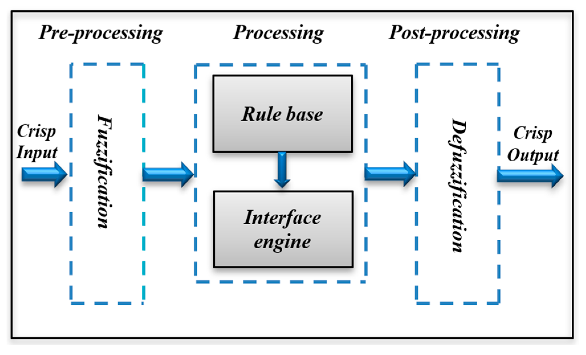
Artificial intelligence technologies such as the fuzzy logic controller (FLC) emulate human cognition to regulate systems and processes. Mamdani fuzzy sets delineate the fuzzy logic controller (FLC) into pre-processing, processing, and post-processing stages. Fuzzy variables are generated from exact inputs during the pre-processing phase. Processing integrates ambiguous inputs using fuzzy membership functions and rules to produce fuzzy output. Imprecise outputs are transformed into precise values for control signals during post-processing. Figure 3 illustrates the three steps of the FLC in a comprehensive block diagram. Controlled systems establish the design of rule bases and membership functions. The subsequent parts address the creation and simplification of FLC. There are three categories of FLC systems [18]. Lotfi A. Zadeh developed the Takagi–Sugeno pure fuzzy system.
Takagi and Sugeno introduced the Takagi–Sugeno (TS) system with clear inputs and mathematical expressions as outputs [21]. Specific inputs and outputs were used to create the Takagi–Sugeno (TS) system to overcome the shortcomings of fuzzy systems. A simple mathematical process generates (TS) outputs. The TS system’s mathematical equations and fuzzy logic’s constraints on some principles make it unclear if it accurately represents human understanding. Thus, the TS system prevents incorrect system installation. The Mamdani/fuzzification–defuzzification system addresses pure fuzzy and Takagi–Sugeno system issues. A fuzzifier converts precise inputs into fuzzy sets in this system. It then uses a defuzzifier to convert fuzzy set outputs to precise values. Reference [17] highlights FLC variety differences. Various fuzzy logic controllers’ mathematical functions demonstrate that the Mamdani model is best for hardware implementation and the most popular in engineering systems. The usual FLC, or Mamdani model, is still the gold standard for engineering systems. This study examines the Mamdani fuzzy logic controller (FLC)’s fuzzy logic.
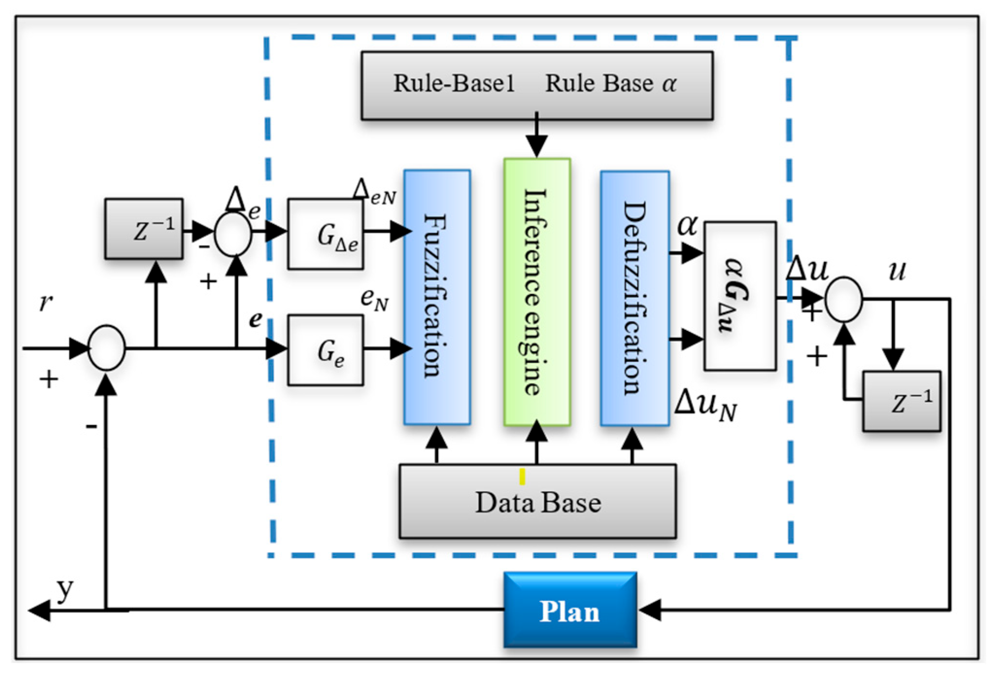
In a conventional fuzzy controller, changing input or output variable membership functions reduces steady-state error. A discrete-time controller with two inputs and one output is examined. Figure 4 identifies the input variables as error e and change in error ∆e:
e k =   r k Y k
e k = e k e k 1 = Y k Y k 1 ,         i f   r k = r k 1  
where y represents the plant’s output and r is the reference command. The current system state is represented by the index (k), whereas the previous state is represented by the index (k − 1). The incremental change in the control signal ∆u(k) is the controller output. One way to obtain the control signal is by calculating the following:
u k = u k 1 + u k .
Figure 5 illustrates the UOD for all membership functions of the controller inputs e, ∆e, and ∆u inside the normalized domain [−1, 1]. NB, NM, NS, ZE, PS, PM, and PB signify negative big, medium, small, zero, positive small, medium, and big. The UOD for the gain update factor α, used to improve the output SF, is normalized within the interval [0, 1], as shown in Figure 6. Zero, extremely tiny, small, moderately big, medium big, huge, and very big are the linguistic values ZE, VS, S, SB, MB, B, and VB. Other than the two fuzzy sets at the extremities (trapezoidal membership functions), symmetric triangles with congruent bases and 50% overlap with neighboring membership functions are used.
The SFs G e , G e , and G u , which execute the precise normalization of input and output variables, serve an equivalent function.
The entire system is depicted in the diagram below.

5. Review on Simplification Techniques for Fuzzy Logic Speed Control

Fuzzy logic controllers (FLCs) are often employed in motor drive applications because of their robust performance against nonlinear dynamics and parameter uncertainties, all without requiring precise mathematical models [22]. Conventional Mamdani-type fuzzy logic controllers often employ dense membership functions and extensive rule bases (e.g., 7 × 7 = 49 rules), rendering them computationally intensive and unsuitable for real-time applications on low-cost processors [18]. Recent research have thus focused on simplification strategies designed to reduce the number of rules and membership functions while preserving control effectiveness.

5.1. Rule Base Reduction

Ref. [12] proposed an early systematic method for simplification by dividing the error–change-of-error phase plane into distinct behavioral regions, retaining a single fuzzy rule for each area. This reduced the number of rules from 49 to either 5 or 9, while maintaining a consistent response pace. Subsequent experiments included evolutionary algorithms, clustering methodologies, and heuristic pruning to identify and eliminate superfluous rules. These strategies significantly reduce the time and memory required for calculations without compromising performance in either the short or long term. Ref. [23] facilitated fuzzy vector control for induction motors by ingeniously integrating overlapping rules, resulting in reduced reaction times and minimal overshoot.

5.2. Membership Function Simplification

Another option to simplify is to reduce membership functions. Normal fuzzy controllers include seven terms: NB, NM, NS, ZE, PS, PM, and PB. They can be reduced to three (negative, zero, and positive) or five (NB, NS, ZE, PS, and PB) for simpler inference [24]. Ref. [25] showed that reduced three-level membership functions can achieve equivalent speed control efficacy with much less computing load. People use adaptive MF tuning and linguistic amalgamation to maintain operational sensitivity.

5.3. Hybrid and Adaptive Simplification

Fuzzy logic is employed with PID, sliding mode, or neural controllers in hybrid control systems. In these systems, fuzzy logic is only used to manage the gains of the controller and the switching modes of the inverter [26]. Adaptive simplification intelligently adapts membership functions or rule weights in real time to compensate for complexity loss [27]. These technologies excel in electric driving systems, where speed and reliability matter.

5.4. Zone-Based and Behavioral Simplification

Zone-based methodologies provide a structured and physically interpretable foundation for fuzzy simplification. Zone-based methodologies partition the error–∆error plane into a limited number of decision zones, each associated with a distinct control action, hence reducing fuzzy controllers to five or nine rules without compromising performance [28]. This is particularly effective for switched reluctance motor (SRM) and permanent magnet synchronous motor (PMSM) drives, as the system’s trajectories remain consistent despite variations in speed. Hafeez and Okumuş proficiently applied simplified fuzzy direct torque control (DTC) to 8/6 switched reluctance motors (SRMs), achieving a reduction in torque ripple with a minimized rule set.

5.5. Simplified Fuzzy Logic Design Using Zone-Based Simplification

This study introduces a zone-based simplification approach designed to enhance fuzzy logic controllers (FLCs) while preserving their dynamic effectiveness and accuracy. The primary objective is to maintain the control precision of Mamdani-type fuzzy logic controllers while simultaneously reducing the quantity of rules and the computational resources required. In motor drive systems such as SRM, PMSM, and DC drives, where error (E) and change in error (ΔE) serve as the primary inputs, the quantity of fuzzy rules increases exponentially with the augmentation of membership functions. A standard configuration using 7 functions per input results in a 7 × 7 matrix comprising 49 rules, while a basic 3 × 3 matrix requires just 9 regulations. The error–Δerror plane is divided into many behavioral regions using zone-based simplification. Every area possesses its own dynamic trajectory. This technique effectively encapsulates the primary reaction of the system in each zone, enabling a reduced number of rules to replicate the overall performance of the controller with no additional effort. The zone-based simplification divides the error–change-of-error (e–Δe) plane into regions to illustrate system evolution. The borders of these zones are determined by the sign and relative size of e and Δe, which indicate whether the motor is speeding up, approaching, or moving away from the reference. The fuzzy controller can respond appropriately at each level since each region requires a particular control action, such as aggressive correction, moderate adjustment, or fine regulation. This structure keeps only the most critical regulations in each operational zone. The control procedure becomes simpler and more efficient [29]. By examining the predominant behavior in each zone—considering trajectory direction and convergence—only one prevailing rule is preserved to characterize that zone. This procedure enables the reduction in the comprehensive rule set to only five essential rules, without substantially compromising control precision.
This work uses zone-based simplification to simplify fuzzy logic rules, utilizing the characteristics of the zone rather than examining the impact of the step response on the system. Initially, the system was planned to operate based on 49 rules, as seen in Table 1.
Subsequently, we will partition Table 1 into nine zones, so condensing the rules to a total of nine and the membership functions to three (N, ZE, and P). The most effective rules will be selected to represent each zone, as seen in Table 2.
In zone 1, the application of NM, NM, NG, and NG rules indicates that the zone’s nature is negative (N).
In zone 2, the application of NG, NG, NM, NP, NP, and NM implies that the zone’s nature is negative (N).
In zone 3, NP, ZE, ZE, and PP were implemented, indicating the characteristics of the ZE zone.
In zone 4, NG, NG, NG, NM, NM, and NP were applied; here, the majority of the rules are negative (N).
In zone 5, the rules NM, NP, ZE, NP, ZE, PP, ZE, PP, and PM were implemented. As shown, three negative and positive rules cancel each other out, leaving only three zero-error rules (ZE) that characterize the behavior of this zone.
In zone 6, the rules PP, PM, PM, PG, PG, and PG were implemented, with the majority being positive; hence, zone 6 can be denoted as (P).
In zone 7, the rules NP, ZE, ZE, and PP were implemented, with the majority being zero-error; hence, zone 7 can be denoted as (ZE).
In zone 8, the rules PP, PM, PG, PM, PG, and PG were applied, with the majority being positive; hence, zone 8 can be denoted as (P).
In the zone 9, the rules P, PG, PG, and PG were applied, with the majority being positive; hence, zone 6 can be denoted as (P).
After this process, the system will be reduced to nine rules and it will simplify the complexity of the fuzzy logic system as it shown in Table 3.
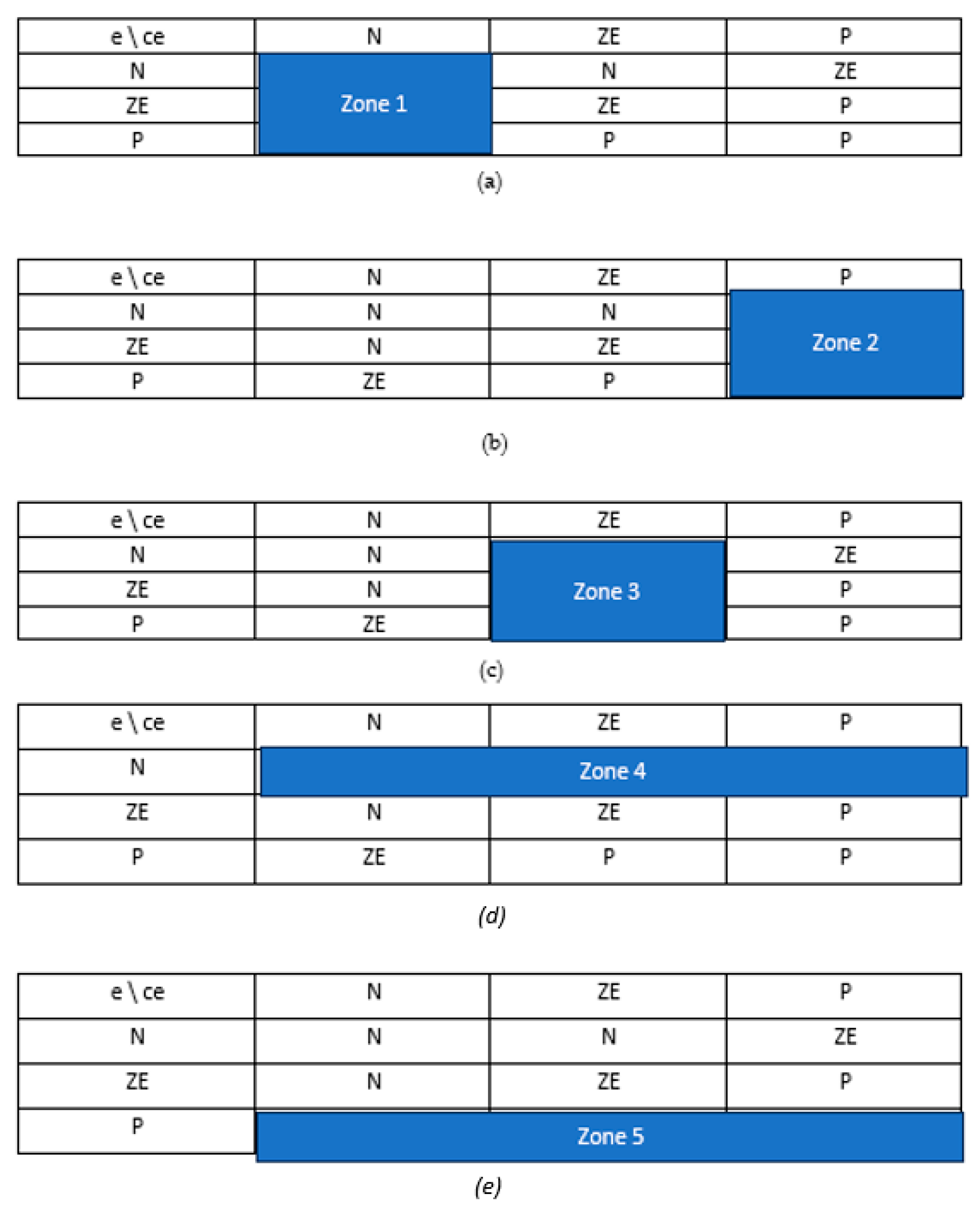
By using the same method, we can simplify the system into five zones as shown in Figure 7:
Here, the rules will also be divided into five rules; by taking many of the rules, we can determine the rules’ nature.
In zone 1, the rules N, N, and ZE were applied and it can be seen that the majority of the rules are negative (N).
In zone 2, the rules ZE, P, and P were applied and it can be seen that the majority of the rules are positive (P).
In zone 3, the rules N, ZE, and P were applied, and it can be seen that the positive rule P can cancel out the negative rule N and many of the rules are zero-error (ZE) rules.
In zone 4, the rules N, N, and ZE were applied and it can be seen that most of the rules are negative (N).
In zone 5, the rules ZE, P, and P were applied and it can be seen that many of the rules are positive (P).
By using this method, the rules were simplified to only five rules as shown in Table 4.

6. Results and Discussion

To assess the functionality and efficacy of the suggested design and simplification of the FLC regulations, a speed controller for the SRM was employed. The motor parameters are presented in the Table 5.
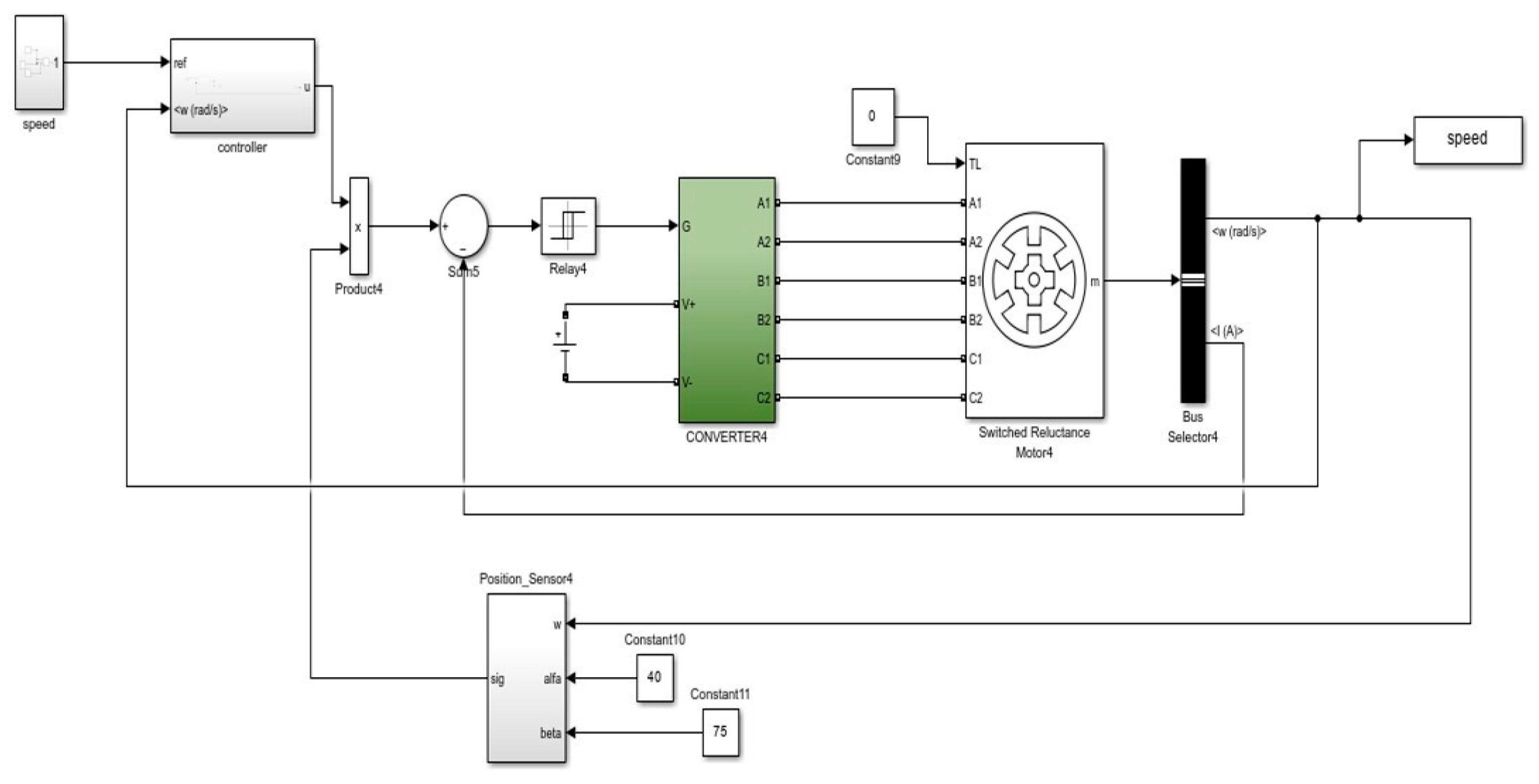
Below is an image of the operation of the principal control system for the switched reluctance motor (SRM) drive. All components—the feedback sensors, the converter/inverter, the fuzzy logic controller, and the speed control loop—interact collaboratively. The fuzzy controller produces a control signal (Δu) to govern the system, factoring in the speed error (e) and the change in error (Δe). The signal’s magnitude is modified and thereafter delivered to the converter that provides power to the SRM. The data supplied by speed and current sensors facilitates precise management and maintains system stability over time.The structure of the system is shown in Figure 8.
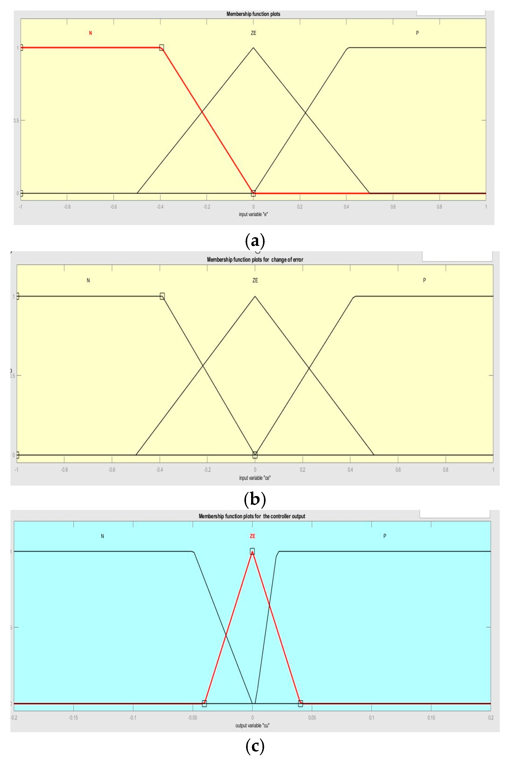
The fuzzy logic controller utilizes three linguistic terms—negative (N), zero (ZE), and positive (P)—for both input variables, which are specified within the normalized range of [−1, 1] as shown in Figure 9. This arrangement guarantees symmetrical and seamless transitions between control zones. The output variable (Δu) dictates the incremental control action implemented on the converter, within the range of [−0.2, 0.2]. Triangular and trapezoidal membership functions were used to provide straightforward calculations and seamless inference surfaces, ensuring steady dynamic performance under diverse load and speed situations.
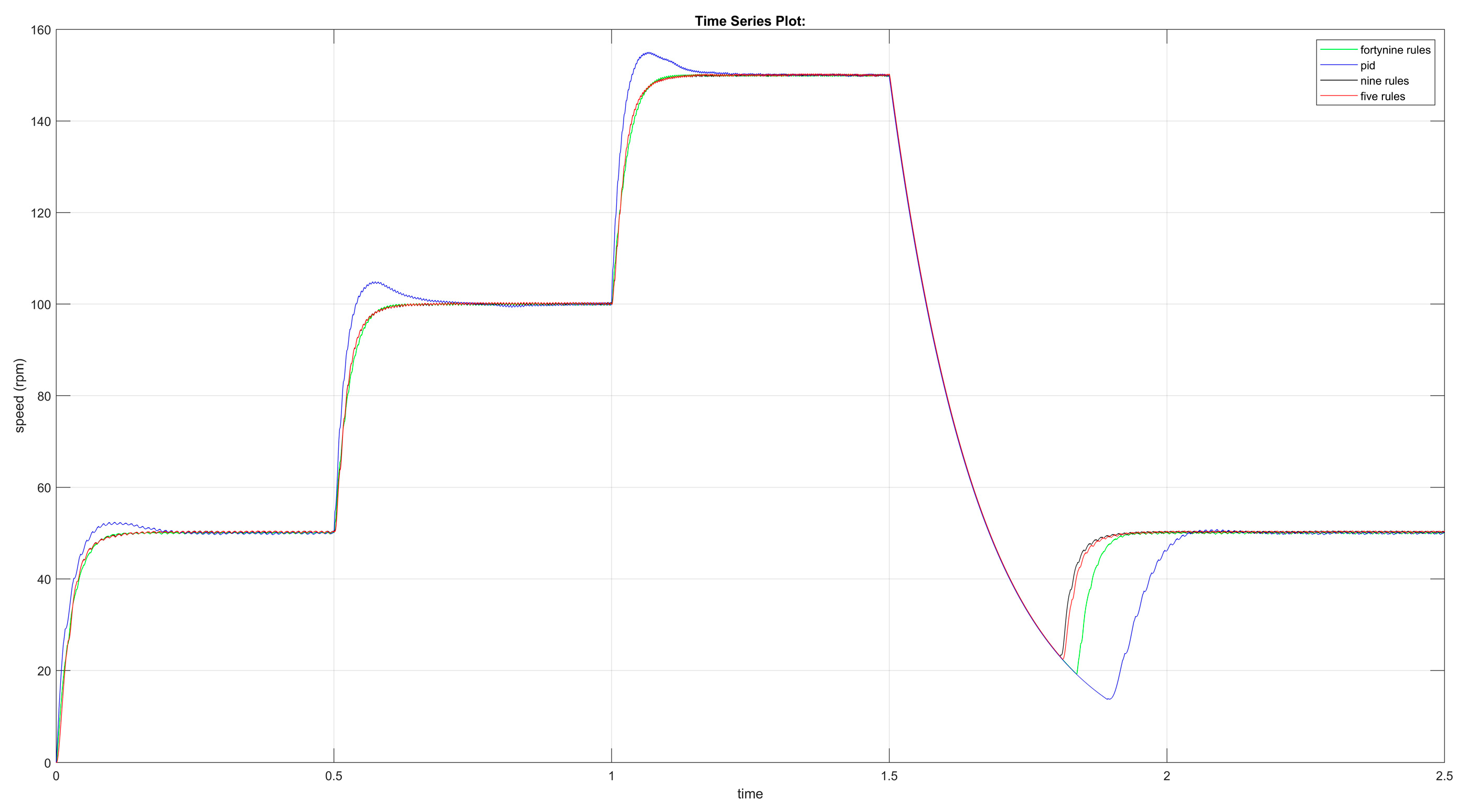
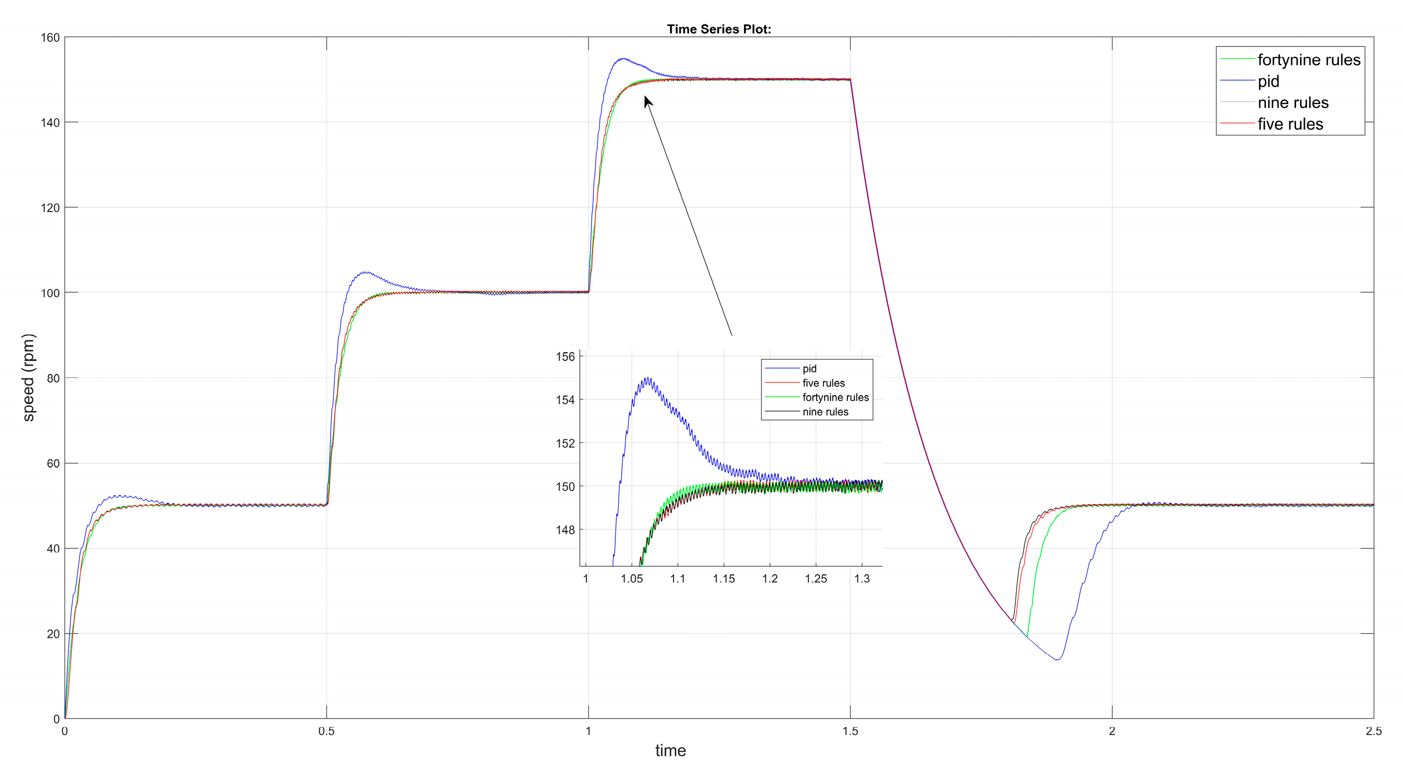
The motor has been tested across many speed ranges using different types of controllers. At low speeds (50 rpm), the 5-rule controller outperforms the PID controller and shows comparable efficacy to the intricate 49-, 9- and 5-rule systems, as depicted in Figure 10.
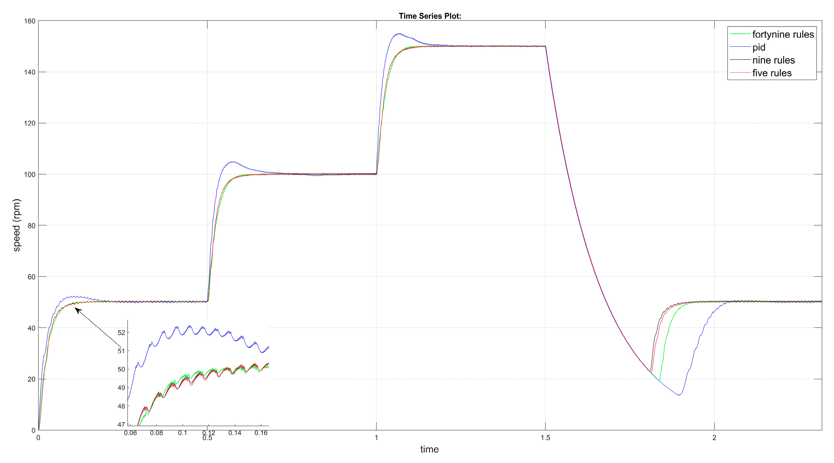
At low speed, the motor has been tested for 50 rpm and, as shown from the result, the PID has an overshoot of about 10–15%. The fuzzy logic controller has minimal overshoot and faster settling and because of the heavier rule base, the 49-rule fuzzy logic controller slightly lagged behind the others as shown in Figure 11.
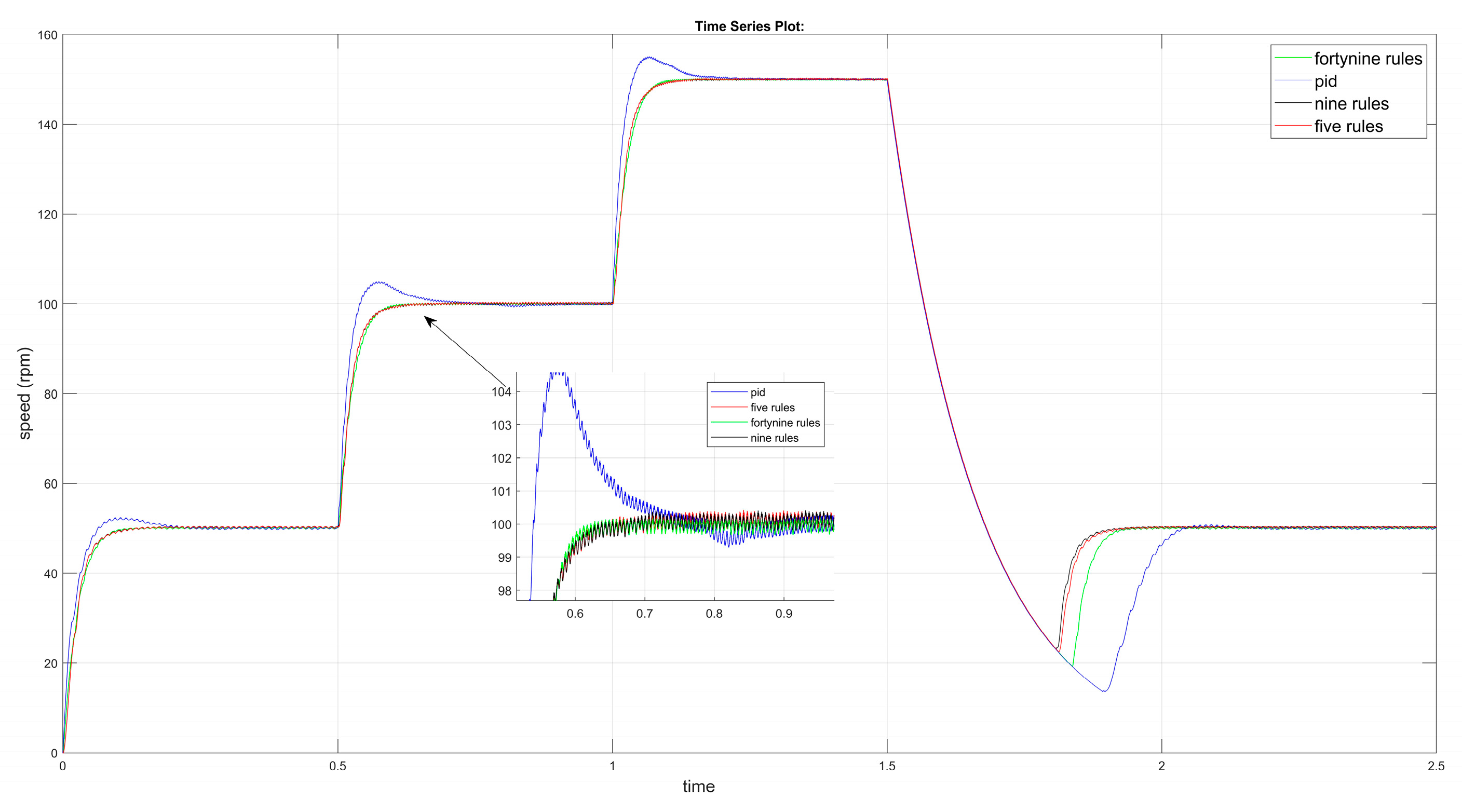
In medium speed ranges (100 rpm) as shown in Figure 12, the simplified fuzzy logic also shows a comparable performance to a complex 49- and 9-rule system while PID overshoots to ~106 rpm before settling; in contrast, the fuzzy controllers stay within ±2 rpm of the target, exhibiting stable damping.
Also, the test has been conducted for high speeds (around 150 rpm) and shows that the PID controllers have a poorer performance than the fuzzy logic controllers. The test demonstrates that there is no difference between the simplified five-rule fuzzy logic and the other nine-rule and forty-nine-rule fuzzy logic systems as shown in Figure 13.
Table 6 facilitates the comparison of controller performance metrics. PID controllers exhibit greater overshoot and extended settling times, in comparison to fuzzy logic controllers.

7. Conclusions

This study proposed a zone-based simplified fuzzy logic controller (SFLC) for efficient and reliable speed regulation of switched reluctance motors (SRMs). The controller effectively reduces the fuzzy rule base while maintaining a dynamic performance comparable to that of a full fuzzy logic system. Simulation outcomes revealed that the simplified controller delivers faster settling time, reduced overshoot, and enhanced robustness when compared with conventional PI/PID controllers, particularly under nonlinear and low-speed operating conditions.
The proposed zoning framework offers a meaningful control-oriented interpretation of the fuzzy decision process, linking each control region to specific motor dynamic behaviors such as acceleration and steady-state response. While the simplification significantly lowers computational load, slight performance deviations may occur during rapid transient or highly nonlinear states. Future research will focus on adaptive and self-tuning zoning mechanisms and real-time hardware implementation, aiming to extend the controller’s applicability to practical industrial drive systems.
The suggested zone-based simplification technique significantly decreases processing demands, although it may compromise accuracy during rapid transient or highly nonlinear operational scenarios. In certain locations, the diminished rule base may inadequately account for quick torque or flux fluctuations, leading to minor overshoot or temporary discrepancies. Future enhancements may involve adaptive or self-tuning zones to improve robustness across broader operating ranges. Future work will extend this research toward real-time hardware validation and integration with hybrid intelligent controllers to further enhance industrial applicability.

Author Contributions

Conceptualization, A.U.; methodology, A.U.; software, A.I.K.K. and A.U.; validation, A.U. and A.I.K.K.; formal analysis, A.U.; investigation, A.U. and A.I.K.K.; resources, A.U. and A.I.K.K.; data curation, A.I.K.K.; writing—original draft preparation, A.U. and A.I.K.K.; writing—review and editing, A.U. and A.I.K.K.; visualization, A.U.; supervision, A.U.; project administration, A.U. All authors have read and agreed to the published version of the manuscript.

Funding

This research received no external funding.

Data Availability Statement

Data are contained within the article.

Acknowledgments

We extend our gratitude to the Institute of Graduate Studies at Istanbul Aydın University for their support and collaboration throughout this study is also much appreciated. This work was completed thanks to their academic and technical support.

Conflicts of Interest

The authors declare no conflicts of interest.

Abbreviations

SRMSwitched Reluctance Motor
FLCFuzzy Logic Controller
SFLCSimplified Fuzzy Logic Controller
PIDProportional–Integral–Derivative
ANNArtificial Neural Network
ANFISAdaptive Neuro-Fuzzy Inference System
SMCSliding Mode Controller
ZEZero Error
MFMembership Function
UODUniverse of Discourse
DTCDirect Torque Control
PIProportional–Integral
PMSMPermanent Magnet Synchronous Motor
AIArtificial Intelligence

References

  1. Maksoud, H.A. Torque Ripple Minimization of a Switched Reluctance Motor using a Torque Sharing Function based on the Overlap Control Technique. Eng. Technol. Appl. Sci. Res. 2020, 10, 5371–5376. [Google Scholar] [CrossRef]
  2. Saleh, A.L.; Al-Amyal, F.; Számel, L. Control techniques of switched reluctance motors in electric vehicle applications: A review on torque ripple reduction strategies. AIMS Electron. Electr. Eng. 2024, 8, 104–145. [Google Scholar] [CrossRef]
  3. García-Amorós, J.; Andrada, P.; Blanqué, B. Assessment of Linear Switched Reluctance Motor’s Design Parameters for Optimal Performance. Electr. Power Compon. Syst. 2015, 43, 810–819. [Google Scholar] [CrossRef]
  4. Desai, P.; Krishnamurthy, M.; Schofield, N.; Emadi, A. Novel Switched Reluctance Machine Configuration with Higher Number of Rotor Poles Than Stator Poles: Concept to Implementation. IEEE Trans. Ind. Electron. 2010, 57, 649–659. [Google Scholar] [CrossRef]
  5. Corda, J.; Jamil, S.M. Experimental Determination of Equivalent-Circuit Parameters of a Tubular Switched Reluctance Machine With Solid-Steel Magnetic Core. IEEE Trans. Ind. Electron. 2010, 57, 304–310. [Google Scholar] [CrossRef]
  6. Zhang, B.; Han, J.; Ma, R. Adaptive fuzzy control of nonlinear aeroelastic system with measurement noise. J. Vibroeng. 2021, 23, 1184–1195. [Google Scholar] [CrossRef]
  7. Talib, M.H.N.; Ibrahim, Z.; Rahim, N.A.; Zulhani, R.; Nordin, N.; Farah, N.; Razali, A. An improved simplified rules Fuzzy Logic Speed Controller method applied for induction motor drive. ISA Trans. 2020, 105, 230–239. [Google Scholar] [CrossRef]
  8. Ismail, M.Z.; Talib, M.H.N.; Ibrahim, Z.; Lazi, J.M.; Rasin, Z. Experimental simplified rule of self tuning fuzzy logic-model reference adaptive speed controller for induction motor drive. Indones. J. Electr. Eng. Comput. Sci. 2020, 20, 1653. [Google Scholar] [CrossRef]
  9. Shi, J.; Mi, Q.; Cao, W.; Zhou, L. Optimizing BLDC motor drive performance using particle swarm algorithm-tuned fuzzy logic controller. SN Appl. Sci. 2022, 4, 293. [Google Scholar] [CrossRef]
  10. Ma, M.; Ling, F.; Li, F.; Liu, F. Torque ripple suppression of switched reluctance motor by segmented harmonic currents injection based on adaptive fuzzy logic control. IET Electr. Power Appl. 2020, 14, 325–335. [Google Scholar] [CrossRef]
  11. Song, B.; Xiao, Y.; Xu, L. Design of fuzzy PI controller for brushless DC motor based on PSO–GSA algorithm. Syst. Sci. Control Eng. 2020, 8, 67–77. [Google Scholar] [CrossRef]
  12. Hai, T.; Zhou, J.; Furukawa, N. Performance enhancement of fuzzy-PID controller for MPPT of PV system to extract maximum power under different conditions. Soft Comput 2024, 28, 2035–2054. [Google Scholar] [CrossRef]
  13. Mahjoub, S.; Labdai, S.; Chrifi-Alaoui, L.; Drid, S.; Derbel, N. Design and implementation of a Fuzzy logic supervisory based on SMC controller for a Dual Input-Single Output converter. Int. J. Electr. Power Energy Syst. 2023, 150, 109053. [Google Scholar] [CrossRef]
  14. Abdel-Aziz, A.; Elgenedy, M.; Williams, B. Review of Switched Reluctance Motor Converters and Torque Ripple Minimisation Techniques for Electric Vehicle Applications. Energies 2024, 17, 3263. [Google Scholar] [CrossRef]
  15. Bechaouech, H.; Van den Bossche, A.; Ibrahim, M. Switched reluctance machine configurations with higher number of rotor poles. In Proceedings of the ICCEE’18 International Conference on Communications and Electrical Engineering, Tokyo, Japan, 12–14 October 2018. [Google Scholar]
  16. Miron, A.; Cziker, A.C.; Beleiu, H.G. Fuzzy Control Systems for Power Quality Improvement—A Systematic Review Exploring Their Efficacy and Efficiency. Appl. Sci. 2024, 14, 4468. [Google Scholar] [CrossRef]
  17. Vidal-Martínez, R.; García-Martínez, J.R.; Rojas-Galván, R.; Álvarez-Alvarado, J.M.; Gozález-Lee, M.; Rodríguez-Reséndiz, J. A Review of Mamdani, Takagi–Sugeno, and Type-2 Fuzzy Controllers for MPPT and Power Management in Photovoltaic Systems. Technologies 2025, 13, 422. [Google Scholar] [CrossRef]
  18. Shill, P.C.; Akhand, M.A.H.; Asaduzzaman, M.D.; Murase, K. Optimization of Fuzzy Logic Controllers with Rule Base Size Reduction using Genetic Algorithms. Int. J. Inf. Technol. Decis. Mak. 2015, 14, 1063–1092. [Google Scholar] [CrossRef]
  19. Dombi, J.; Rigó, P.R. The construction of multidimensional membership functions and its application to feasibility problems. Fuzzy Sets Syst. 2023, 469, 108634. [Google Scholar] [CrossRef]
  20. Hassani, H.; Zarei, J. Interval Type-2 fuzzy logic controller design for the speed control of DC motors. Syst. Sci. Control. Eng. 2015, 3, 266–273. [Google Scholar] [CrossRef]
  21. Cordon, O.; Herrera, F. A proposal for improving the accuracy of linguistic modeling. IEEE Trans. Fuzzy Syst. 2000, 8, 335–344. [Google Scholar] [CrossRef]
  22. Goswami, R.; Joshi, D. Performance Review of Fuzzy Logic Based Controllers Employed in Brushless DC Motor. Procedia Comput. Sci. 2018, 132, 623–631. [Google Scholar] [CrossRef]
  23. Cerruto, E.; Consoli, A.; Raciti, A.; Testa, A. Fuzzy Adaptive Vector Control of Induction Motor Drive. Power Electronics. IEEE Trans. Power Electron. 1997, 12, 1028–1040. [Google Scholar] [CrossRef]
  24. Lima, J.F.; Patiño-León, A.; Orellana, M.; Zambrano-Martinez, J.L. Evaluating the Impact of Membership Functions and Defuzzification Methods in a Fuzzy System: Case of Air Quality Levels. Appl. Sci. 2025, 15, 1934. [Google Scholar] [CrossRef]
  25. Tarbosh, Q.A.; Aydogdu, O.; Farah, N.; Talib, H.N.; Salh, A.; Cankaya, N.; Omar, F.A.; Durdu, A. Review and Investigation of Simplified Rules Fuzzy Logic Speed Controller of High Performance Induction Motor Drives. IEEE Access 2020, 8, 49377–49394. [Google Scholar] [CrossRef]
  26. Yilmaz, B.M.; Tatlicioglu, E.; Savran, A.; Alci, M. Adaptive fuzzy logic with self-tuned membership functions based repetitive learning control of robotic manipulators. Appl. Soft Comput. 2021, 104, 107183. [Google Scholar] [CrossRef]
  27. Tatlicioglu, E.; Yilmaz, B.M.; Savran, A.; Alci, M. Adaptive fuzzy logic with self-adjusting membership functions based tracking control of surface vessels. Ocean. Eng. 2022, 253, 111129. [Google Scholar] [CrossRef]
  28. Mitra, P.; Dey, C.; Mudi, R.K. Fuzzy rule-based set point weighting for fuzzy PID controller. SN Appl. Sci. 2021, 3, 651. [Google Scholar] [CrossRef]
  29. Zhao, Z.; Wang, T.; Yu, J.; Basin, M.V. Bilateral Cooperative Control of Nonlinear Multiagent Systems with State and Output Quantification. IEEE Trans. Cybern. 2025, 55, 2949–2957. [Google Scholar] [CrossRef]
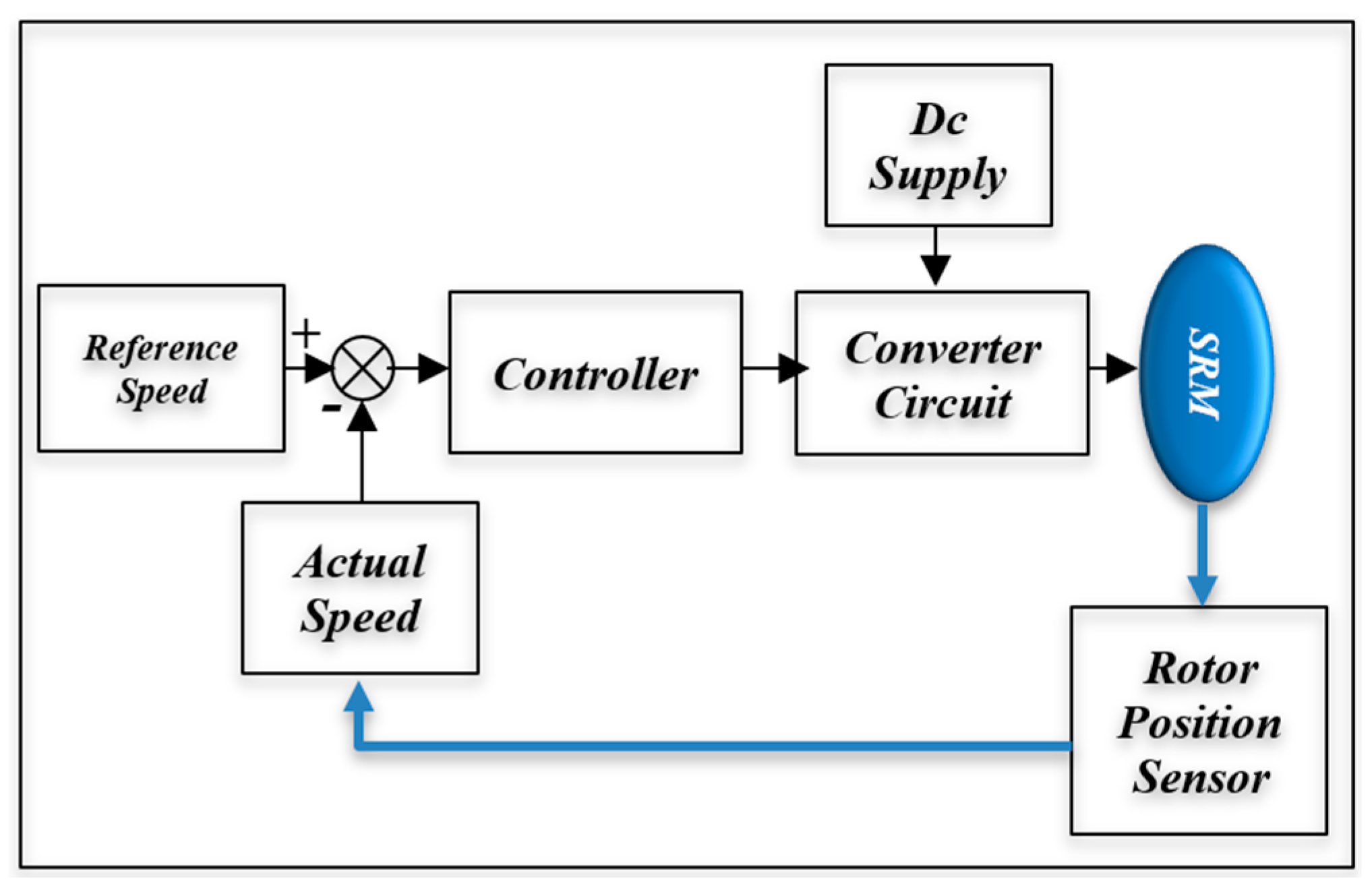
Figure 2. Block diagram of SRM speed control.
Electronics 14 04248 g002
Figure 3. FLC operation stages block diagram.
Electronics 14 04248 g003
Figure 4. Block diagram of a conventional PIFC.
Electronics 14 04248 g004
Figure 5. Membership is a function of e , Δ e , and Δ u .
Electronics 14 04248 g005
Figure 6. The gain updating factor’s membership function α .
Electronics 14 04248 g006
Figure 7. Five-zone categorization: classification of five-zone fuzzy rule tables for the simplification of speed controllers, (a) representing zone 1, (b) representing zone 2, (c) representing zone 3, (d) representing zone 4, (e) representing zone 5.
Electronics 14 04248 g007
Figure 8. Block diagram of the complete fuzzy logic-based SRM speed control system.
Electronics 14 04248 g008
Figure 9. Fuzzy membership functions defining the control surface: (a) error input, (b) change-of-error input, and (c) controller output.
Electronics 14 04248 g009
Figure 10. Speed step response for PID and (49-9-5) fuzzy logic rules.
Electronics 14 04248 g010
Figure 11. Low-speed step response for PID and (49-9-5) fuzzy logic rules.
Electronics 14 04248 g011
Figure 12. Medium-speed step response for PID and (49-9-5) fuzzy logic rules.
Electronics 14 04248 g012
Figure 13. High-speed step response for PID and (49-9-5) fuzzy logic rules.
Electronics 14 04248 g013
Table 1. Forty-nine rules for controlling the speed of SRM.
ΔE\ENGNMNPZEPPPMPG
NGNGNGNGNGNMNPZE
NMNMNMNPNPNMZEPP
NPNGNGNMNPZEPPPM
ZENGNMNPZEPPPMPG
PPNMNPZEPPPMPGPG
PMNPZEPPPMPGPGPG
PGZEPPPMPGPGPGPG
Table 2. Zone selection for the 9 rules.
ΔE\ENGNMNPZEPPPMPG
NGZone 1Zone 2Zone 3
NM
NPZone 4Zone 5Zone 6
ZE
PP
PMZone 7Zone 8Zone 9
PG
Table 3. Nine rules for controlling the speed of SRM.
e\ceNZEP
NNNZE
ZENZEP
PZEPP
Table 4. Five rules for controlling the speed of SRM.
e\ceNZEP
N N
ZENZEP
P P
Table 5. SRM motor parameters.
ParameterValueUnit
Motor type6/4-
Stator resistance0.01Ohm
Unaligned inductance0.67 × 10−3H
Aligned inductance23.6 × 10−3H
Saturated aligned inductance0.15 × 10−3H
Inertia0.0082kg·m2
Friction0.05N·m·s
Maximum current450A
Maximum flux linkage0.486V·s
Table 6. Performance comparison between PID controller and different rule size of fuzzy logic controllers.
Reference StepPID49-Rule FLC9-Rule FLC5-Rule FLC
1st step (~50 rpm)noticeable (~10%)minimal (~2–3%)minimalminimal
2nd step (~100 rpm)high (~7–10%)slight (~2%)negligiblenegligible
3rd step (~150 rpm)highest (~8–10%)moderate (~3%)very lowvery low
Disclaimer/Publisher’s Note: The statements, opinions and data contained in all publications are solely those of the individual author(s) and contributor(s) and not of MDPI and/or the editor(s). MDPI and/or the editor(s) disclaim responsibility for any injury to people or property resulting from any ideas, methods, instructions or products referred to in the content.