Abstract
Multifunctional metasurfaces, capable of flexible electromagnetic wave manipulation, have become a focus of research for their high integration and utility. In particular, those operating simultaneously in transmission and reflection modes have attracted growing interest, as they integrate multiple functions within a single aperture, save physical space, and further expand wave control capabilities across full space. In this work, an inspiring strategy of transmission-reflection-integrated bifunctional metasurface by hybridizing geometric phase and propagation phase is proposed. The transmission and reflection modes can be independently and flexibly controlled in full space: the co-polarized reflection under left-handed circular polarization (LCP) incidence is governed by rotation-induced geometric phase modulation, while the co-polarized transmission under right-handed circular polarization (RCP) incidence is modulated through scaling-induced propagation phase modulation. Moreover, arbitrary amplitude modulation of the co-polarized transmission under RCP incidence can be realized by incorporating lumped resistors. As a proof of concept, a bifunctional meta-device is constructed, which can generate vortex beam carrying arbitrary topological charge for LCP reflected wave and achieve high-quality holographic imaging for RCP transmitted wave. Both the simulated and experimental results validate the feasibility of the proposed strategy, which significantly enhances the integration density of multifunctional metasurfaces while reducing inter-functional crosstalk, expanding its potential applications in electronic engineering. Moreover, it can also serve as a fundamental machine learning platform, facilitating multimodal fusion and cross-modal learning in radar signals and visual imaging.
1. Introduction
Metasurfaces [1], as two-dimensional (2D) planar artificial structures composed of subwavelength meta-atoms, offer significant advantages over conventional three-dimensional metamaterials, including simple fabrication, low profile, and low loss. These platforms have garnered extensive research interest due to their remarkable ability to flexibly manipulate the amplitude [2,3], phase [4,5], and polarization [6,7] of electromagnetic waves. As a result, they have been widely employed across a variety of applications from terahertz to optical regimes, such as anomalous refraction/reflection [8,9], polarization conversion [10], radar cross section reduction [11,12], orbital angular momentum (OAM) beam generation [13,14], holographic imaging [15,16], metalenses [17,18], and so on.
Nevertheless, despite these remarkable capabilities, conventional single-functional metasurfaces are increasingly inadequate to fulfill the growing demands of practical applications. In response to the ongoing pursuit of miniaturization and high integration, multifunctional metasurfaces have emerged as a prominent research frontier, attracting considerable attention for their potential to deliver diverse and reconfigurable wave-control capabilities within a single platform. Extending the function of metasurfaces is crucial in terms of economics and design difficulty. In general, the use of the independent characteristics of frequency and polarization for guiding the design of metasurfaces to achieve additional functionalities is feasible. However, metasurface operations are limited to a half-space, transmission or reflection mode, without effectively manipulating the EM wave of full space. Metasurfaces with asymmetric transmission properties enable direction-dependent wave manipulation, and have been further developed to support diversified functions across multiple frequencies or under different polarization states. For linear polarizations (LP), efficient wavefront control can be achieved via propagation phase modulation. However, as the propagation phase affects both LCP and RCP waves equally, it offers limited polarization diversity. In contrast, the geometric phase, also known as the Pancharatnam–Berry (PB) phase [19,20], induced by rotating meta-atoms, provides complementary phase profiles for circular polarizations and enables distinct responses in cross-polarized transmission or co-polarized reflection channels. By combining propagation and geometric phases, metasurfaces can achieve independent control of orthogonal circular polarizations, leading to proposals for CP-bifunctional devices [21,22]. Nevertheless, most such designs remain constrained to two polarization states, operate in half-space, and suffer from mutual interference between functions, which limits their ability to perform multiple tasks simultaneously under a single incident wave. Currently, some work has also been conducted on full-space metasurfaces in the THz or optical frequency bands. However, due to manufacturing challenges and experimental testing environments, it is difficult to extend these to the microwave frequency band [23,24,25]. Through relentless efforts, researchers have proposed full-space metasurfaces operating in the microwave band. For instance, Reference [26] demonstrates independent control of reflection and transmission channels at low and high frequencies. However, achieving simultaneous control of transmission and reflection channels at the same frequency point remains a significant technical challenge.
In this work, an inspiring strategy of transmission-reflection-integrated bifunctional metasurface by hybridizing geometric phase and propagation phase is proposed. The transmission and reflection modes can be independently and flexibly controlled in full space: the co-polarized reflection under LCP incidence is governed by rotation-induced geometric phase modulation, while the co-polarized transmission under RCP incidence is modulated through scaling-induced propagation phase modulation. Moreover, the arbitrary amplitude modulation of the co-polarized transmission under RCP incidence can be realized by incorporating lumped resistors. As a proof of concept and as illustrated in Figure 1, a bifunctional meta-device is constructed, which can generate vortex beam carrying topological charge l = −2 for LCP reflected wave and achieve high-quality holographic imaging “O” for RCP transmitted wave. Both the simulated and experimental results validate the feasibility of the proposed strategy. Our finding significantly enhances the integration density of multifunctional metasurfaces while reducing inter-functional crosstalk, expanding its potential applications in electronic engineering.
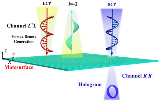
Figure 1.
Schematic diagram of the transmission-reflection-integrated bifunctional metasurface.
2. Results
2.1. Theoretical Analysis
In order to analyze different reflection/transmission amplitude and phase responses for orthogonal CP waves, the Jones matrix is employed here. In the Cartesian coordinate system, a CP wave can be decomposed into orthogonal linear components (e.g., x- and y-polarized waves). Therefore, the incident and transmitted electric field components of a CP incident wave can be represented using those of LP incident waves. For transmission, both x-LP and y-LP incident waves should exhibit high co-polarized transmission and low cross-polarized transmission. The Jones matrix [27,28] can be expressed as:
where and can be expressed as and Here, , and , represent the co-polarized transmission amplitude and phase for x-LP and y-LP incident waves, respectively.
When the x-LP and y-LP waves have identical transmission responses and no propagation phase difference, i.e., when , we have and . Equation (1) then becomes:
Similarly, for reflection, when both x-LP and y-LP incident waves exhibit high co-polarized reflection and low cross-polarized reflection, we have:
where and can be expressed as and . Here, , and , represent the co-polarized reflection amplitude and phase for x-LP and y-LP incident waves, respectively. When the x-LP and y-LP waves have identical reflection responses but exhibit a π reflection phase difference, i.e., when , we have and . Equation (3) then becomes:
From the above analysis, when the designed unit cell satisfies , and , , it can achieve high-efficiency co-polarized reflection and orthogonal polarization transmission for CP incident waves. If the upper structure reflects LCP incident waves and transmits RCP incident waves, the overall unit cell will enable independent control of the LCP co-polarized reflected wave and the RCP co-polarized transmitted wave. This facilitates a spatial-polarization dual-decoupling design for orthogonal CP waves. Furthermore, according to Equations (3) and (4), the co-polarized transmission phase for the RCP wave depends solely on the lower unit cell. Adjusting the geometric parameters of the lower structure within the unit cell allows control of the RCP co-polarized propagation phase. Changing the geometric parameters of the upper structure or rotating it does not affect the propagation phase. Simultaneously, the presence of the upper structure enables high-efficiency co-polarized reflection for LCP incident waves.
In summary, the design principle is confirmed based on the properties of the P-B geometric phase: rotating the entire upper structure modulates the co-polarized reflection phase for the LCP wave, while changing the geometric parameters of the lower structure does not affect the reflection phase. Therefore, arranging these unit cells periodically or quasi-periodically allows for the independent design of phase profiles in the reflection and transmission spaces. Specifically, the P-B geometric phase can be used to generate the corresponding electromagnetic functionality in the reflection space with the LCP co-polarized reflected wave, while the longitudinally coupled propagation phase can be used to generate the corresponding electromagnetic functionality in the transmission space with the RCP co-polarized transmitted wave. These two functionalities can be achieved completely independently.
2.2. Meta-Atom Design
Based on the analysis of the synergistic control mechanism of P-B geometric phase and longitudinally coupled propagation phase, the unit cell structure shown in Figure 2a is designed. The dielectric substrate used throughout this paper is F4B material (relative permittivity εr = 2.65, loss tangent tanδ = 0.001). The unit cell consists of an upper double-layer chiral structure and a lower six-layer metallic square patch structure. The upper chiral structure comprises two layers of etched single-sided cross-shaped metal patterns. Adjusting the rotational angle difference between these two cross layers imparts helix-like properties, enabling it to reflect one CP incident wave while transmitting its orthogonal counterpart. The geometric parameters of the lower six-layer metallic square patch structures are identical. After optimizing the geometric parameters, the final determined parameters are as follows: unit cell period P = 10.0 mm; thickness of the F4B substrate for the upper chiral structure d1 = 1.5 mm; thickness of the F4B substrates within the lower six-layer structure d2 = 1.0 mm; other geometric dimensions for the upper chiral structure: l1 = 8.0 mm, l2 = l3 = 2 mm, and l4 = 4 mm; rotational angle difference between the two cross layers α = 60°; and other geometric dimension for the lower structure: w = 0.2 mm (line width). Meanwhile, the metal material is copper with a thickness of 0.017 mm for all layers.
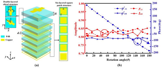
Figure 2.
(a) Schematic of the unit cell; (b) simulated , , , and as rotation angle θ of the upper chiral structure changes at 9.0 GHz.
The electromagnetic response of the unit cell was simulated using the frequency domain solver in CST MICROWAVE STUDIO. Figure 2b shows the simulated , , , and as the rotation angle θ of the upper chiral structure changes at 9.0 GHz. It can be seen that when the upper chiral structure is rotated by an angle θ, the RCP co-polarized propagation phase , RCP co-polarized transmission amplitude , and LCP co-polarized reflection amplitude remain almost unchanged. In contrast, the LCP co-polarized reflection phase acquires a P-B geometric phase of −2θ, consistent with Jones matrix analysis. Therefore, the LCP co-polarized reflection phase can be controlled via the P-B geometric phase obtained by rotating the upper chiral structure, achieving a full 360° phase shift coverage for with θ rotation within 180°.
Due to the presence of the upper chiral structure, most of the energy of an LCP incident wave is reflected, while most of the energy of an RCP incident wave is transmitted. Consequently, the RCP co-polarized propagation phase depends only on the geometric parameters of the lower patch structure within the unit cell. After optimizing and fixing the geometric parameters of the upper chiral structure, the influence of the multi-layer patch structure’s geometric parameters on the RCP co-polarized propagation phase is discussed. Figure 3 shows the simulated , , and at 9.0 GHz for 12 unit cells selected based on varying geometric parameters of the multi-layer patch structure. It can be observed that under the premise of maintaining high-efficiency LCP co-polarized reflection and RCP co-polarized transmission, the LCP co-polarized reflection phase is almost unaffected. The RCP co-polarized propagation phase between adjacent unit cells differs by approximately 30°. Therefore, the of the selected 12 unit cells achieves full 360° phase coverage. The geometric parameters of these 12 unit cells are listed in Table 1.
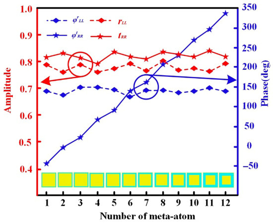
Figure 3.
Simulated , , and for the selected 12 unit cells at 9.0 GHz.

Table 1.
Geometric parameters of the selected 12 unit cells.
Furthermore, the amplitude of the RCP co-polarized transmitted wave can be additionally controlled by loading lumped resistors onto the metal frames within the multi-layer patch structure. The schematic is shown in Figure 4a. Taking unit cell No. 1 from the selected set as an example, its simulated , , and at 9.0 GHz as the lumped resistor value are shown in Figure 4b. The figure shows that loading lumped resistors onto the metal frames has almost no effect on the LCP co-polarized reflection amplitude , phase , and RCP co-polarized propagation phase . However, as the lumped resistor value increases from 0 Ω to 300.0 Ω, the RCP co-polarized transmission amplitude decreases from 83% to 20%, indicating that can be arbitrarily controlled between 20% and 83% by adjusting the resistor value. By simulating 1.wmf at 9.0 GHz for the 12 selected unit cells under different resistor values, the required resistor values for each unit cell at specific amplitudes can be determined. To facilitate subsequent metasurface construction, where appropriate resistor values need to be selected for different unit cells, the amplitude range from 1.0 to 0.0 is divided into 8 levels. The corresponding required lumped resistor values for each unit cell at each level are listed in Table 2. Here, Tr1 represents the resistor value required for a unit cell to achieve an amplitude level between 1.0 and 0.8, Tr2 represents the value for the level between 0.8 and 0.7, and so on for Tr3, Tr4, Tr5, Tr6, Tr7, and Tr8.
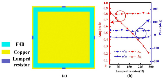
Figure 4.
(a) Schematic of the unit cell with lumped resistors loaded on the metal frames; (b) simulated , , and as lumped resistor value changes for unit cell 1 at 9.0 GHz.

Table 2.
Required lumped resistor values for the selected 12 unit cells across 8 amplitude levels.
In summary, rotating the upper chiral structure and adjusting the geometric parameters of the lower multi-layer patch structure enable independent and flexible control of the phase for the LCP co-polarized reflected wave and the phase for the RCP co-polarized transmitted wave, both achieving 360° phase coverage. Additionally, loading lumped resistors onto the metal frames of the multi-layer patch structure allows arbitrary control of the RCP co-polarized transmission amplitude .
2.3. Designs and Simulations of the Transmission-Reflection-Integrated Bifunctional Metasurface
When constructing the transmission-reflection-integrated bifunctional metasurface, the following procedure can be used: first, based on the required co-polarized propagation phase distribution for the RCP wave to achieve the desired electromagnetic functionality in transmission space, select unit cells from Table 1 whose is closest to the theoretical phase at each position. Then, based on the required transmission amplitude distribution for that functionality, refer to Table 2 to determine the required lumped resistor value Tr for each arranged unit cell. Finally, based on the required co-polarized reflection phase distribution for the LCP wave to achieve the desired electromagnetic functionality in reflection space, rotate the entire upper chiral structure for each unit cell. The rotation angle for each chiral structure is . This method enables a decoupled design for LCP and RCP waves. The constructed transmission-reflection-integrated bifunctional metasurface can also achieve independent electromagnetic functionalities in the transmission and reflection spaces for the two CP incident waves by independently controlling the phase and amplitude distributions of the LCP and RCP waves.
Vortex electromagnetic waves, characterized by helical phase fronts, have broad prospects in fields like encrypted communications and radar detection. Vortex waves carry both spin angular momentum (SAM) and orbital angular momentum (OAM) [29,30], expressed as:
where represents the amplitude of the electromagnetic wave, r represents the radial distance between the coordinate axis and a point on the wave, φ represents the azimuthal angle, and l can be any integer, representing the OAM topological charge number.
Theoretically, the infinite integer values of l and the mutual orthogonality of different-order OAM waves provide vortex waves with numerous non-interfering transmission modes during propagation. This offers advantages such as high spectral utilization efficiency and enhanced security. Phase-modulated metasurface-based vortex wave generators can efficiently generate vortex beams with arbitrary topological charges over broad bandwidths. However, unresolved crosstalk issues with other electromagnetic functionalities often confine vortex wave generators to single-channel operation, limiting the integration with other EM functions.
Holographic imaging technology [31] can generate high-quality holographic images and has wide applications in imaging. This technology generally uses wave interference to record the amplitude and phase information of an object wave, then utilizes the diffraction principle of light to reconstruct this information, achieving the imaging effect. Compared to traditional holographic devices, metasurface-based holographic imagers offer advantages such as thin profiles, simple fabrication, and high imaging resolution. Nevertheless, current solutions mostly reconstruct object amplitude and phase information in only a single channel. The challenge of integrating them with other electromagnetic functions without significant crosstalk urgently needs resolution.
To generate a high-quality holographic image, the amplitude and phase distributions on the holographic imager can be calculated using the Rayleigh–Sommerfeld Diffraction Theory [32]:
where represents the electric field distribution on the holographic imager plane, represents the electric field distribution on the imaging plane, λ is the wavelength at the operating frequency, k is the wave number at the operating frequency, represents the distance between a point (x0, y0, L) on the imaging plane and a point (x, y, 0) on the holographic image, and represents the obliquity factor. Based on the target electric field distribution of the hologram on the imaging plane, the amplitude and phase distributions on the holographic image can be derived, enabling the construction of the corresponding holographic imager. For comparative verification, the reversibility of optical paths can be utilized: the amplitude and phase distributions on the holographic image can be used to inversely derive the electric field distribution of the generated holographic image on the imaging plane.
Based on the design theory and unit cell characteristics described above, a transmission-reflection-integrated bifunctional metasurface was constructed. At 9.0 GHz, it achieves high-quality holographic imaging in the RCP transmission channel and generates a vortex wave carrying a topological charge l = −2 in the LCP reflection channel. The metasurface comprises 40 × 40 unit cells, with a total size of 400 mm × 400 mm.
For the transmission channel, theoretical calculation results of the metasurface are shown in Figure 5a. The constructed metasurface transmits the RCP incident wave at 9.0 GHz and reconstructs the English letter “O”, and the target hologram is shown in Figure 5a(I). The distance between the transmission channel imaging plane and the metasurface is set to 200 mm. Based on Equation (6) and the target hologram in Figure 5a(I), the required transmission phase distribution and transmission amplitude distribution for the metasurface were calculated, shown in Figure 5a(II,III), respectively. The subsequent distributions were followed: first, unit cells from the pre-selected 12 types in Table 1 whose is closest to the theoretical phase at each position were arranged; second, referring to Table 2, the required lumped resistor value Tr for each arranged unit cell was determined; finally, Equation (6) was used to calculate the theoretical hologram corresponding to the transmission channel of the metasurface, shown in Figure 5a(IV).
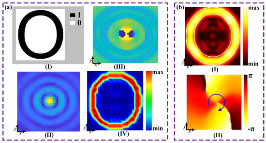
Figure 5.
(a) Theoretical calculation results of the metasurface; (I) target hologram for the transmission channel of the metasurface; (II) transmission amplitude distribution; (III) transmission phase distribution; (IV) theoretical hologram. (b) Simulation results of the metasurface; (I) phase distribution of the Ex component on the xoy plane at z = −200 mm; (II) phase distribution of the Ex component on the xoy plane at z = 200 mm.
For the reflection channel, the constructed metasurface reflects the LCP incident wave at 9.0 GHz to generate a vortex wave carrying topological charge l = −2. The required LCP co-polarized reflection phase distribution is given by:
where l = −2 is the topological charge carried by the vortex wave, and (x, y) are the 2D coordinates on the metasurface. Based on the phase distribution calculated from Equation (7), the upper chiral structure of each unit cell was rotated as a whole. The rotation angle for each chiral structure is . This arrangement yields the final transmission-reflection-integrated bifunctional metasurface.
The constructed metasurface was simulated using the time domain solver in CST. To allow RCP or LCP waves to illuminate the metasurface normally along the −z direction, a CP plane wave source was placed along the +z direction of the metasurface. For RCP plane wave incidence, the electric field distribution on the xoy plane at z = −200 mm was monitored using a field monitor in CST. Simulation results of the metasurface are shown in Figure 5b. As shown in Figure 5b(I), the metasurface successfully reconstructed a clear contour of the letter “O” in the transmission channel. Similarly, for LCP plane wave incidence, the electric field distribution on the xoy plane at z = 200 mm was monitored, and the phase distribution of the Ex component on this plane was extracted. As shown in Figure 5b(II), the phase distribution of the Ex component exhibits a helical shape, shifting by 4π (from −π to π) clockwise, confirming that the metasurface successfully generated a vortex beam with a topological charge l = −2 in the reflection channel.
3. Experiment and Discussion
To validate the proposed design method, an experimental sample of the transmission-reflection-integrated bifunctional metasurface with identical geometric parameters to the simulation model was fabricated using printed circuit board (PCB) technology, as shown in Figure 6a. All the design structures, patterns, and lumped-resistor-loads are on F4B substrates. To minimize the influence of the external environment, testing was conducted in an anechoic chamber. The test environment and experimental setup are shown in Figure 6b. Two ports of a vector network analyzer (VNA) were connected to a scanning probe and a CP horn antenna, respectively. To approximate the simulation boundary conditions and ensure the CP wave emitted by the horn antenna illuminated the sample approximately as a plane wave, the horn antenna was aligned with the center of the sample, maintaining a distance of at least 30 λ0. The scanning probe, controlled by a motorized stage, scanned the electric field distribution over the test area at a constant speed.
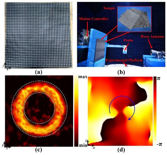
Figure 6.
(a) Fabricated sample of the metasurface; (b) test environment and experimental setup; (c) measured phase distribution of the Ex component on the xoy plane at z = −200 mm under RCP wave incidence; (d) measured phase distribution of the Ex component on the xoy plane at z = 200 mm under LCP wave incidence.
For functional validation of the transmission channel, the scanning probe and horn antenna were placed on opposite sides of the sample. The probe distance was 200 mm, scanning an area of 450 mm × 450 mm. At 9.0 GHz, with RCP wave illumination, the electric field intensity distribution on the xoy plane at z = −200 mm successfully reconstructed the letter “O”, as shown in Figure 6c. For functional validation of the reflection channel, the scanning probe and horn antenna were placed on the same side of the sample. The probe distance was also 200 mm, scanning an area of 450 mm × 450 mm. At 9.0 GHz, with LCP wave illumination, a vortex wave with a topological charge l = −2 was generated in reflection space, as shown in Figure 6d. These experimental results are consistent with simulation and theoretical calculations, effectively validating the proposed design method for the transmission-reflection-integrated bifunctional metasurface.
4. Conclusions
In this work, an inspiring strategy of transmission-reflection-integrated bifunctional metasurface by hybridizing geometric phase and propagation phase is proposed. For the transmission mode, the co-polarized transmission under RCP incidence is modulated through scaling-induced propagation phase modulation; for the reflection mode, the co-polarized reflection under LCP incidence is governed by rotation-induced geometric phase modulation. In addition, arbitrary amplitude modulation of the co-polarized transmission under RCP incidence can be realized by incorporating lumped resistors. As a proof of concept, a bifunctional meta-device is constructed which can generate vortex beam carrying arbitrary topological charge for LCP reflected wave and achieve high-quality holographic imaging for RCP transmitted wave. Both the simulated and experimental results validate the feasibility of the proposed strategy. Our finding significantly enhances the integration density of multifunctional metasurfaces while reducing inter-functional crosstalk, expanding its potential applications in electronic engineering. Moreover, it can also serve as a fundamental machine learning platform, facilitating multimodal fusion and cross-modal learning in radar signals and visual imaging.
Author Contributions
Conceptualization, Z.L. and Z.W.; methodology, Z.W.; software, T.L.; validation, Z.L.; formal analysis, Z.W.; investigation, J.G. and Y.S.; resources, J.W.; data curation, J.G.; writing—original draft preparation, Z.L.; writing—review and editing, J.Z. and H.S.; visualization, Z.L.; supervision, J.W.; project administration, Y.S.; funding acquisition, J.W. All authors have read and agreed to the published version of the manuscript.
Funding
The authors are grateful for the support from the National Key Research and Development Program of China (Grant No.2022YFB3806200), and the National Natural Science Foundation of China (Grant Nos. 61971435, 61971437, 62101588, 62101589).
Data Availability Statement
Data are contained within the article.
Conflicts of Interest
The authors declare no conflicts of interest.
Abbreviations
The following abbreviations are used in this manuscript:
| LCP | Left-handed circular polarization |
| RCP | Right-handed circular polarization |
| OAM | orbital angular momentum |
| LP | linear polarizations |
| PB | Pancharatnam–Berry |
References
- Chen, H.T.; Taylor, A.J.; Yu, N. A review of metasurfaces: Physics and applications. Rep. Prog. Phys. 2016, 79, 076401. [Google Scholar] [CrossRef] [PubMed]
- Yu, N.; Genevet, P.; Kats, M.A.; Aieta, F.; Tetienne, J.P.; Capasso, F.; Gaburro, Z. Light propagation with phase discontinuities: Generalized laws of reflection and refraction. Science 2011, 334, 333–337. [Google Scholar] [CrossRef] [PubMed]
- Kim, T.T.; Kim, H.; Kenney, M.; Park, H.S.; Kim, H.; Min, B.; Zhang, S. Amplitude modulation of anomalously refracted terahertz waves with gated-graphene metasurfaces. Adv. Opt. Mater. 2018, 6, 1700507. [Google Scholar] [CrossRef]
- Zheng, C.; Li, J.; Yue, Z.; Li, J.; Liu, J.; Wang, G.; Wang, S.; Zhang, Y.; Zhang, Y.; Yao, J. All-dielectric trifunctional metasurface capable of independent amplitude and phase modulation. Laser Photonics Rev. 2022, 16, 2200051. [Google Scholar] [CrossRef]
- Fan, Q.; Liu, M.; Zhang, C.; Zhu, W.; Wang, Y.; Lin, P.; Yan, F.; Chen, L.; Lezec, H.J.; Lu, Y.; et al. Independent amplitude control of arbitrary orthogonal states of polarization via dielectric metasurfaces. Phys. Rev. Lett. 2020, 125, 267402. [Google Scholar] [CrossRef]
- Ran, Y.; Liang, J.; Cai, T.; Li, H. High-performance broadband vortex beam generator using reflective Pancharatnam-Berry metasurface. Opt. Commun. 2018, 427, 101–106. [Google Scholar] [CrossRef]
- Akram, M.R.; Ding, G.; Chen, K.; Feng, Y.; Zhu, W. Ultrathin single layer metasurfaces with ultra-wideband operation for both transmission and reflection. Adv. Mater. 2020, 32, 1907308. [Google Scholar] [CrossRef]
- Chen, H.; Wang, J.; Ma, H.; Qu, S.; Xu, Z.; Zhang, A.; Yan, M.; Li, Y. Ultra-wideband polarization conversion metasurfaces based on multiple plasmon resonances. J. Appl. Phys. 2014, 115, 154504. [Google Scholar] [CrossRef]
- Li, Y.F.; Zhang, J.Q.; Qu, S.B.; Wang, J.-F.; Zheng, L.; Zhou, H.; Xu, Z.; Zhang, A.-X. Wide-band circular polarization-keeping reflection mediated by metasurface. Chin. Phys. B 2015, 24, 014202. [Google Scholar] [CrossRef]
- Su, P.; Zhao, Y.; Jia, S.; Shi, W.; Wang, H. An ultra-wideband and polarization-independent metasurface for RCS reduction. Sci. Rep. 2016, 6, 20387. [Google Scholar] [CrossRef]
- Sang, D.; Chen, Q.; Ding, L.; Guo, M.; Fu, Y. Design of checkerboard AMC structure for wideband RCS reduction. IEEE Trans. Antennas Propag. 2019, 67, 2604–2612. [Google Scholar] [CrossRef]
- Fu, X.; Yang, J.; Wang, J.; Jia, Y.; Wang, Z.; Han, Y.; Chen, H.; Jiang, J.; Ding, C.; Li, Y.; et al. Active-passive compound metasurface for simultaneously manipulating radiation and scattering in wide band. Mater. Des. 2023, 230, 111932. [Google Scholar] [CrossRef]
- Cheng, L.; Hong, W.; Hao, Z. Generation of electromagnetic waves with arbitrary orbital angular momentum modes. Sci. Rep. 2014, 4, 4814. [Google Scholar] [CrossRef]
- Yu, S.; Li, L.; Shi, G.; Zhu, C.; Zhou, X.; Shi, Y. Design, fabrication, and measurement of reflective metasurface for orbital angular momentum vortex wave in radio frequency domain. Appl. Phys. Lett. 2016, 108, 121903. [Google Scholar] [CrossRef]
- Li, L.; Cui, T.J.; Ji, W.; Liu, S.; Ding, J.; Wan, X.; Li, Y.B.; Jiang, M.; Qiu, C.-W.; Zhang, S. Electromagnetic reprogrammable coding-metasurface holograms. Nat. Commun. 2017, 8, 197. [Google Scholar] [CrossRef] [PubMed]
- Zhao, R.; Sain, B.; Wei, Q.; Tang, C.; Li, X.; Weiss, T.; Huang, L.; Wang, Y.; Zentgraf, T. Multichannel vectorial holographic display and encryption. Light. Sci. Appl. 2018, 7, 95. [Google Scholar] [CrossRef] [PubMed]
- Aieta, F.; Kats, M.; Genevet, P.; Capasso, F. Multiwavelength achromatic metasurfaces by dispersive phase compensation. Science 2015, 347, 1342–1345. [Google Scholar] [CrossRef]
- Zhu, W.; Song, Q.; Yan, L.; Zhang, W.; Wu, P.; Chin, L.K.; Cai, H.; Tsai, D.P.; Shen, Z.X.; Deng, T.W.; et al. A flat lens with tunable phase gradient by using random access reconfigurable metamaterial. Adv. Mater. 2015, 27, 4739–4743. [Google Scholar] [CrossRef]
- Ling, X.; Xiao, W.; Chen, S.; Zhou, X.; Luo, H.; Zhou, L. Revisiting the anomalous spin-Hall effect of light near the Brewster angle. Phys. Rev. A 2021, 103, 033515. [Google Scholar] [CrossRef]
- Cohen, E.; Larocque, H.; Bouchard, F.; Nejadsattari, F.; Gefen, Y.; Karimi, E. Geometric phase from Aharonov-Bohm to Pancharatnam-Berry and beyond. Nat. Rev. Phys. 2019, 1, 437–449. [Google Scholar] [CrossRef]
- Jia, Y.; Wang, J.; Han, Y.; Zhu, R.; Zhang, Z.; Yang, J.; Meng, Y.; Li, Y.; Qu, S. Quasi-omnibearing retro-reflective metagrating protected by reciprocity. Photonics Res. 2022, 10, 843–854. [Google Scholar] [CrossRef]
- Faraz, F.; Li, Z.; Zhang, Z.; Rehman Abbasi, T.U.; Wang, X.; Rukhlenko, I.D.; Zhu, W. High-Efficiency Geometric Phase Metasurface with Multifold Rotationally Symmetric Resonators. ACS Appl. Opt. Mater. 2022, 1, 173–178. [Google Scholar] [CrossRef]
- Deng, J.; Duan, J.; Fu, R.; Geng, Y.; Lu, H.; Gao, F.; Yan, B. Full-space metasurfaces for independent manipulation of transmission and reflection. Opt. Lett. 2024, 49, 4934–4937. [Google Scholar] [CrossRef]
- Wang, Y.; He, X.; Wu, M.; Lu, G.; Geng, Z.; Qu, Y. High-efficiency full-space terahertz holography with interleaved Janus metasurfaces. Opt. Lasers Eng. 2025, 195, 109250. [Google Scholar] [CrossRef]
- Ebrahimi, K.; Mehrzad, Z.; Javadi, S.; Mili, M.R.; Jorswieck, E.; Al-Dhahir, N. Stacked Intelligent Metasurfaces and STAR-RIS-enabled Terahertz ISAC System. IEEE Trans. Veh. Technol. 2025, 1–6. [Google Scholar] [CrossRef]
- Wang, C.; Xu, H.; Liu, T.; Zhang, F. Hybrid-phase assisted amplitude and phase control using full-space metasurface. Adv. Opt. Mater. 2024, 12, 2302153. [Google Scholar] [CrossRef]
- Jones, R. A new calculus for the treatment of optical systems I. description and discussion of the calculus. J. Opt. Soc. Am. 1941, 31, 488–493. [Google Scholar] [CrossRef]
- Menzel, C.; Rockstuhl, C.; Lederer, F. Advanced Jones calculus for the classification of periodic metamaterials. Phys. Rev. A 2010, 82, 053811. [Google Scholar] [CrossRef]
- Bai, Y.; Lv, H.; Fu, X.; Yang, Y. Vortex beam: Generation and detection of orbital angular momentum. Chin. Opt. Lett. 2022, 20, 012601. [Google Scholar] [CrossRef]
- Li, S.J.; Li, Z.Y.; Huang, G.S.; Bin Liu, X.; Li, R.Q.; Cao, X.Y. Digital coding transmissive metasurface for multi-OAM-beam. Front. Phys. 2022, 17, 62501. [Google Scholar] [CrossRef]
- Gabor, D. A new microscopic principle. Nature 1948, 161, 777–778. [Google Scholar] [CrossRef]
- Liu, L.; Zhang, X.; Kenney, M.; Su, X.; Xu, N.; Ouyang, C.; Shi, Y.; Han, J.; Zhang, W.; Zhang, S. Broadband metasurfaces with simultaneous control of phase and amplitude. Adv. Mater. 2014, 26, 5031–5036. [Google Scholar] [CrossRef] [PubMed]
Disclaimer/Publisher’s Note: The statements, opinions and data contained in all publications are solely those of the individual author(s) and contributor(s) and not of MDPI and/or the editor(s). MDPI and/or the editor(s) disclaim responsibility for any injury to people or property resulting from any ideas, methods, instructions or products referred to in the content. |
© 2025 by the authors. Licensee MDPI, Basel, Switzerland. This article is an open access article distributed under the terms and conditions of the Creative Commons Attribution (CC BY) license (https://creativecommons.org/licenses/by/4.0/).