1. Introduction
The rapid evolution of mobile networks, particularly with the advent of 5G and beyond, has introduced unprecedented demands for flexibility, scalability, and security in communication infrastructures. Among the key architectural paradigms addressing these challenges is network slicing, which enables the creation of multiple logical networks—referred to as slices—over a shared physical infrastructure [
1,
2,
3,
4,
5]. Each slice can be tailored to meet specific Service Level Agreements (SLAs), catering to the diverse requirements of industry verticals such as autonomous vehicles, industrial automation, and e-health.
Virtualization technologies play a central role in the deployment and isolation of network functions within slices [
6,
7,
8,
9]. VMs offer strong isolation and compatibility with legacy applications, making them suitable for slices with stringent security and regulatory needs. In parallel, containers provide lightweight, agile, and resource-efficient virtualization, facilitating the dynamic instantiation and scaling of network functions, especially in cloud-native 5G and future 6G core architectures [
10,
11]. The combination of VMs and containers enables a flexible infrastructure capable of balancing security, performance, and operational efficiency across heterogeneous slicing scenarios.
However, the proliferation of network slicing also amplifies concerns regarding data security and privacy, particularly in multi-tenant environments where slices from different operators or industries coexist on the same physical network [
12,
13,
14]. The impending threat of quantum computing further exacerbates these challenges, as quantum algorithms are expected to break popular and widely used asymmetric cryptographic schemes or algorithms [
15], such as Rivest–Shamir–Adleman (RSA) [
16] and Elliptic Curve Cryptography (ECC) [
17]. In response, the National Institute of Standards and Technology (NIST) [
18] organized a competition aiming to replace the vulnerable asymmetric cryptographic primitives with PQC [
19,
20]. PQC has emerged as a promising solution, offering cryptographic algorithms designed to remain secure even in the presence of quantum adversaries. Integrating PQC into network slicing architectures is essential to future-proof communication security.
At the same time, protecting data in transit across slices and network domains requires robust, standards-based security mechanisms. The IPsec protocol [
21] suite provides confidentiality, integrity, and authentication at Layer 3 (the Network Layer) of the OSI model [
22], making it a fundamental technology for securing communication within and between slices. The combination of IPsec with PQC-based cryptography and key exchange schemes offers a resilient security framework capable of withstanding both classical and quantum attacks.
In this work, we present a comprehensive study on the integration of network slicing with VMs, enhanced by post-quantum cryptography and IPsec, to achieve secure, flexible, and scalable network services. We analyze the system design trade-offs for VMs in slice deployment, integrate PQC algorithms in slice-specific key exchanges, and demonstrate the application of IPsec for slice-level data protection. Through experimental validation, performance measurements and evaluation of our system implementation, we provide insights into the feasibility and effectiveness of combining these technologies for next-generation secure network infrastructures.
2. Virtualization
Virtualization in data centers enables the abstraction of hardware resources and their allocation to multiple isolated computing environments. This abstraction allows for improved resource utilization, simplified management of workloads, and increased system flexibility. It also facilitates reproducibility and portability in software deployment, which is essential for large-scale distributed systems. From a systems perspective, virtualization introduces an additional layer that can influence performance, isolation guarantees, and security.
2.1. Containers
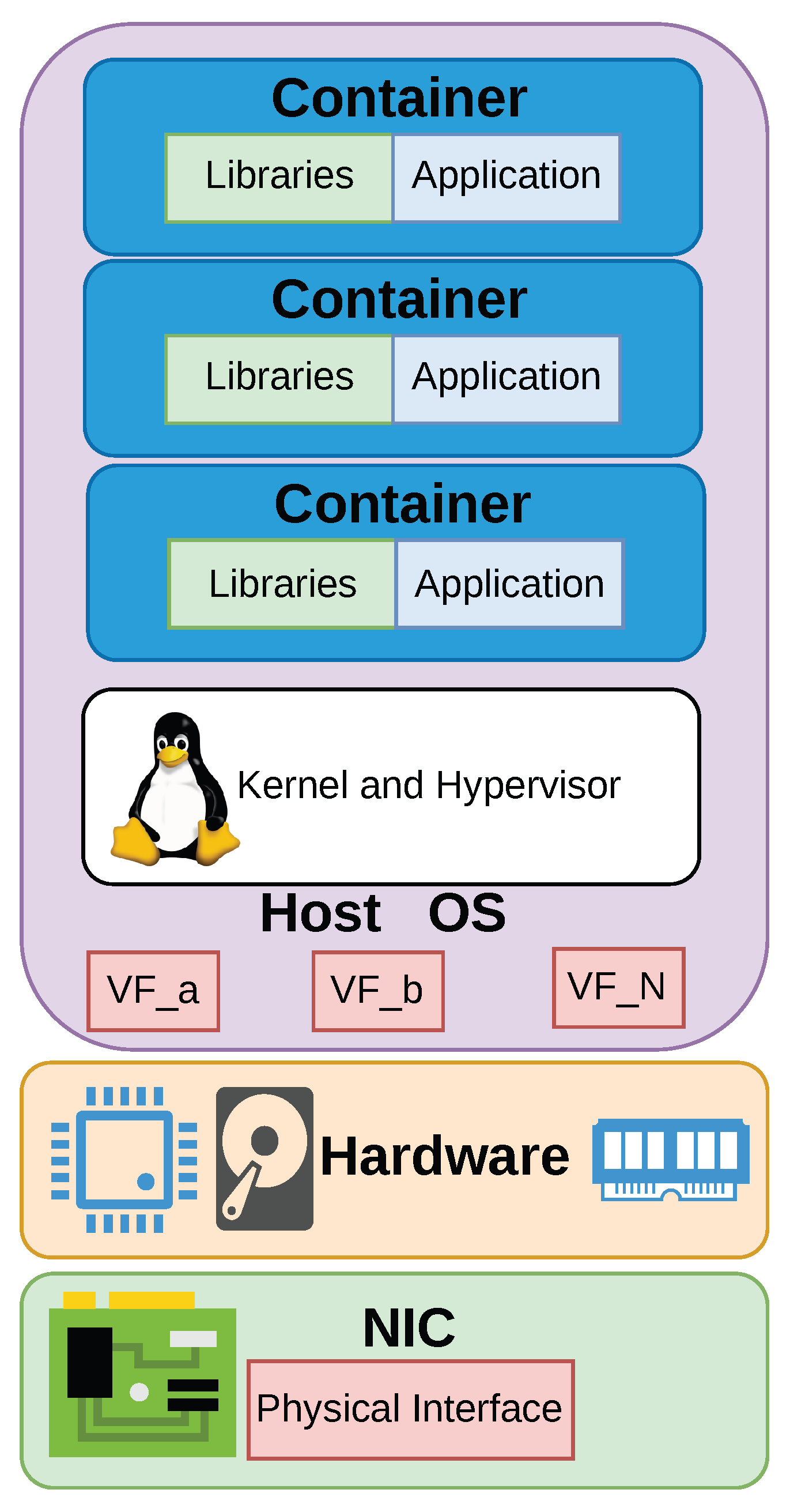
Containers are a type of operating system-level virtualization. The abstraction of a container can be seen in
Figure 1. Within network slicing architectures, containers permit agile, lightweight, and scalable deployment of network functions. Unlike VMs, containers provide process-level isolation with minimal overhead, allowing for faster instantiation, reduced resource consumption, and improved portability across heterogeneous environments [
23]. In the context of network slicing, containers facilitate the dynamic deployment and scaling of Virtualized Network Functions (VNFs) and Service Function Chains (SFCs) that constitute individual slices [
24]. This containerization aligns well with the microservices architecture commonly used in cloud-native 5G core networks and future 6G paradigms, allowing each slice to be composed of independently deployable components tailored to specific SLAs.
Furthermore, container orchestration platforms such as Kubernetes enable automated lifecycle management, load balancing, and fault recovery of slice components, thus supporting the elasticity and reliability demanded by dynamic slicing. The use of containers also enhances multi-tenancy by enabling strong isolation between slices while supporting rapid provisioning and teardown, which is essential for on-demand Network-as-a-Service (NaaS) delivery. Therefore, containerization is a foundational enabler for the flexible, efficient, and programmable realization of network slicing in next-generation mobile networks.
2.2. Virtual Machines
VMs are a form of hardware-level virtualization. The abstraction of a VM can be seen in
Figure 2. They have long served as a foundational technology for enabling Network Function Virtualization (NFV) within network slicing architectures [
25]. VMs provide strong isolation by virtualizing hardware resources and running separate guest operating systems on top of a hypervisor. This hardware-level abstraction makes VMs suitable for scenarios where strict security, tenant separation, and compatibility with legacy systems are paramount. In the context of network slicing, VMs can host VNFs that constitute the control and data planes of a slice, particularly in slices requiring high assurance, compliance, or persistent resource reservations. While VMs typically incur higher overhead in terms of memory and CPU usage compared to containers, they offer robust fault isolation and mature management tooling, making them appropriate for mission-critical or long-lived network services [
26].
Furthermore, VMs can coexist with containers in hybrid infrastructures, where orchestration platforms support both environments to balance security, performance, and agility [
27]. However, the relatively slower instantiation times and lower resource efficiency of VMs can limit their suitability in highly dynamic slicing scenarios, where fast scaling and real-time responsiveness are required. Despite these limitations, VMs continue to play an important role in network slicing deployments, particularly where security, compatibility, or regulatory requirements dominate the design criteria.
In this work, we evaluate our framework, QRoNS, using Virtual Machines. We make this design choice in order to simulate realistic cloud or data center deployments, where each tenant or service may require its own OS, kernel modules, or specific system configurations. VMs can be provisioned with fixed amounts of CPU, memory, and storage, ensuring consistent performance across experiments and preventing resource contention that might otherwise skew results.
3. Security Through Cryptography
The five fundamental security principles, often referred to as the pillars of Information Security and Cybersecurity, are rooted in the well-known CIA triad [
28]. Cryptography plays a crucial role in safeguarding information by ensuring these core principles are upheld [
29]. These principles can be summarized in the following:
Confidentiality—Keeping data secret from unauthorized parties.
Integrity—Ensuring data has not been altered in any way.
Availability—Timely and reliable access to resources for authorized users.
Authentication—Verifying identities of parties or sources.
Non-repudiation—Preventing denial of actions or communications.
As quantum computing rapidly advances, the aforementioned foundational security principles of information security face unprecedented challenges. Classical cryptographic algorithms, such as RSA and ECC, are built on mathematical problems that quantum computers could solve exponentially faster than traditional computers, rendering much of today’s encryption vulnerable to future attacks. This looming threat has prompted a global shift toward PQC, a field dedicated to developing cryptographic algorithms that can withstand both classical and quantum attacks.
PQC leverages mathematical techniques, such as lattice-based, code-based, and hash-based cryptography, which are believed to be resistant to quantum attacks [
30,
31,
32]. Unlike Quantum Key Distribution (QKD), which achieves security by leveraging the fundamental laws of quantum mechanics [
33], PQC is designed to be compatible with existing digital infrastructure, making it a practical and scalable solution for organizations seeking to future-proof their security frameworks. The transition to PQC is essential for maintaining the core pillars of information security in a post-quantum era, ensuring that sensitive data, digital communications, and authentication mechanisms remain protected as quantum computing capabilities continue to evolve.
3.1. Quantum Threat
Quantum computing has been the focus of intensive research for several years [
34]. While fully commercial quantum computers are still on the horizon, early prototypes [
35], digital annealers [
36], and quantum annealers [
37] with comparable characteristics are already available. These developments pose a significant threat to current communication systems, which today rely heavily on classical cryptographic methods. As mentioned before, asymmetric cryptographic algorithms, such as RSA, are particularly vulnerable as they are expected to be broken by this emergence of quantum computing. In contrast, symmetric encryption schemes like the Advanced Encryption Standard (AES) [
38] are considered more resistant, provided their key lengths are doubled [
39]. Consequently, the cryptographic algorithms we currently depend on must be replaced by quantum-resistant alternatives, often referred to as post-quantum cryptography, which are specifically designed to withstand attacks from quantum computers.
3.2. Quantum Resiliency
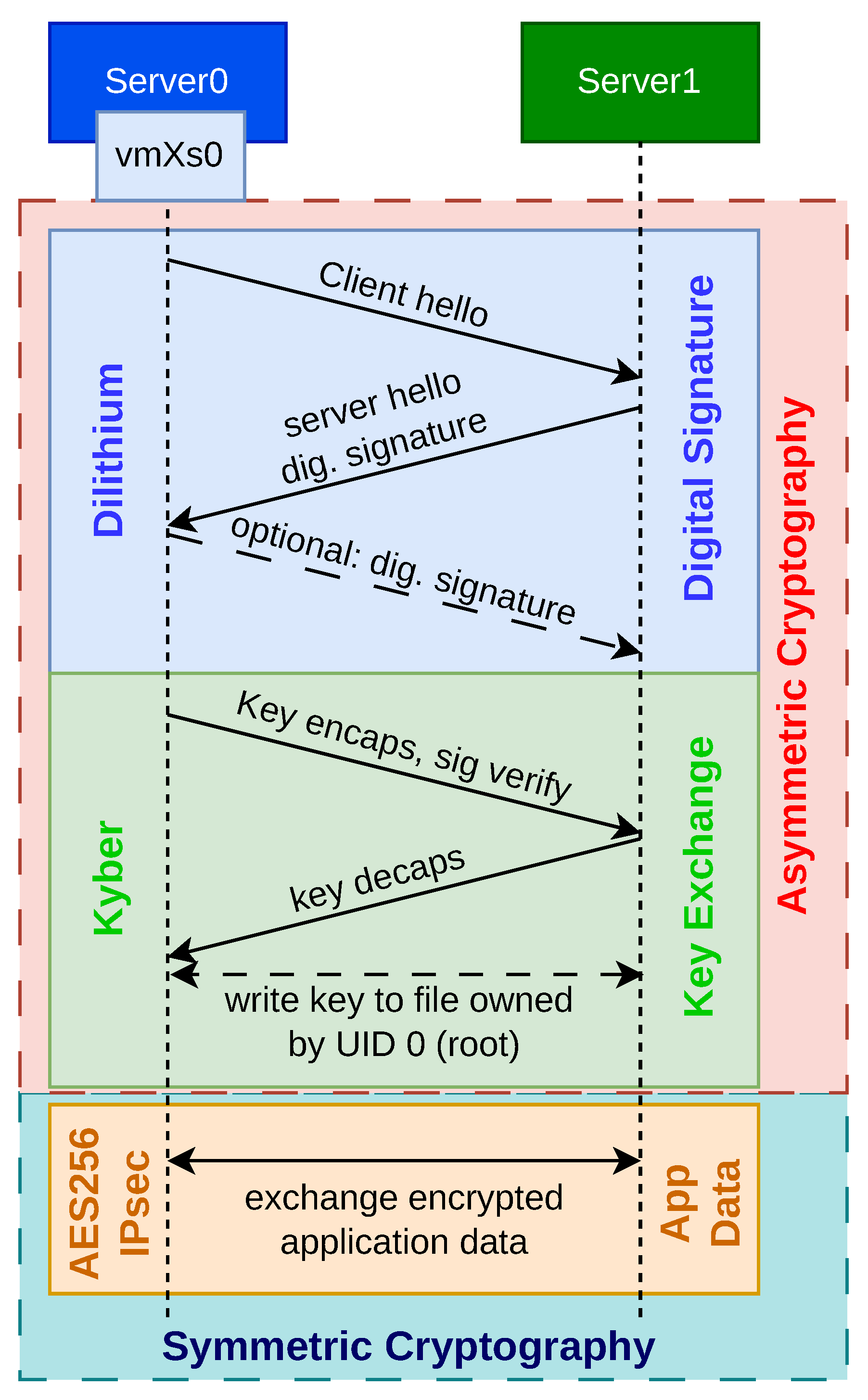
The overall process of establishing a PQC-IPsec quantum-resilient communication channel is illustrated in
Figure 3. Typically, establishing communication between two parties involves three main steps: first, the exchange of digital signatures; second, the negotiation of a shared secret key; and finally, the transmission of application data. The first two steps (digital signature and key exchange) rely on asymmetric cryptography. Digital signatures are used to verify identities, allowing a server to prove its authenticity. Optionally, the server can request that the client also authenticate itself via a digital signature.
Our implementation uses the PQC algorithm Dilithium [
40] for digital signatures, supporting all NIST-standardized security levels: NIST-2 (Dilithium2), NIST-3 (Dilithium3), and NIST-5 (Dilithium5) [
41]. For the key exchange, we employ the NIST-standardized PQC algorithm Kyber [
42], again covering each NIST security level: NIST-2 (Kyber512), NIST-3 (Kyber768), and NIST-5 (Kyber1024) [
43]. This ensures that the resulting shared key is known only to the two communicating parties, even if their communication traverses insecure or untrusted channels.
Higher NIST security levels require more CPU resources to perform the associated cryptographic operations. However, since the signature and key exchange phases occur only once during the initial communication setup, the performance overhead remains manageable. In our experiments, we focus on the most demanding and most secure choice of cryptographic parameters, i.e., Dilithium5 and Kyber1024 (NIST-5). After a successful key exchange, the secure key is stored in a file accessible only to the root user (UID 0) within the virtual machine.
In the final step, the previously exchanged key is retrieved from a secure file and used to configure IPsec rules that encrypt all incoming and outgoing traffic using symmetric encryption. This setup is performed using the xfrm utilities provided by the iproute2-6.11.0 package in the Linux kernel [
44]. Once the IPsec rules are installed, symmetric cryptography is employed to protect the application data. For our experiment, we utilize the IPsec protocol in combination with AES-256 in Galois/Counter Mode (GCM) for encryption.
Even when data is exchanged between a VM and any other type of host (physical or virtualized), quantum-resilient security is preserved, even in scenarios where the underlying host system is compromised. Thanks to the use of post-quantum cryptographic algorithms, quantum-resilient communication is ensured even over insecure networks.
3.3. IPsec
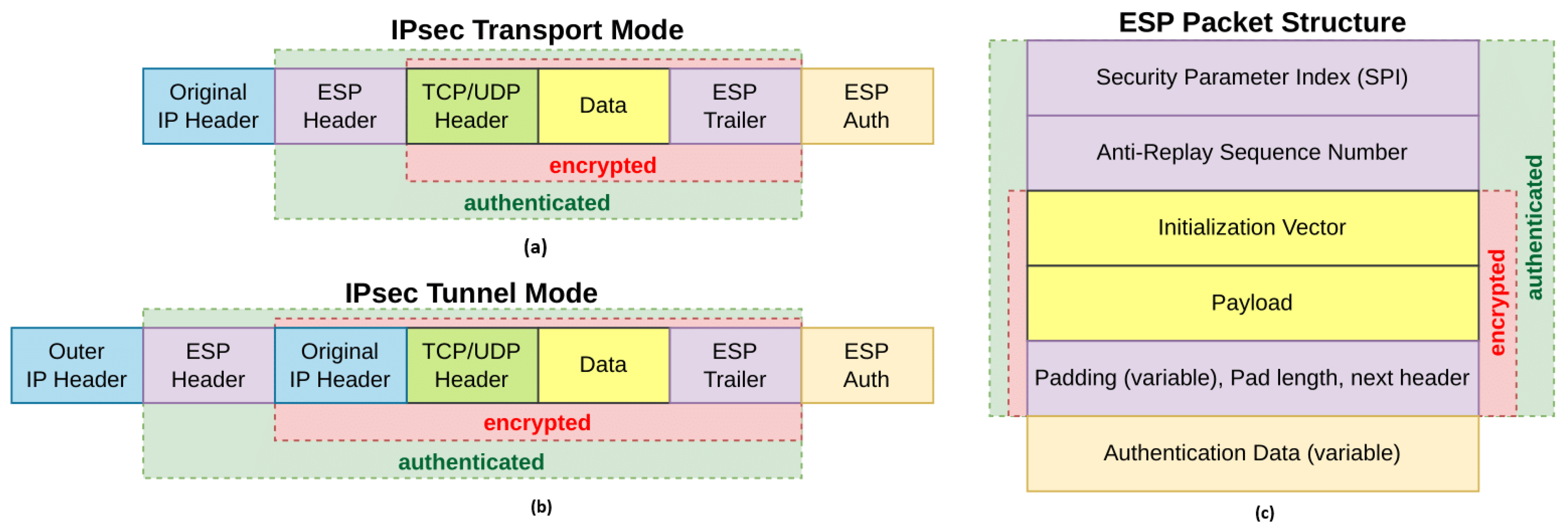
Internet Protocol security (IPsec) is a widely adopted protocol suite designed to provide secure communication at the IP layer through mechanisms such as authentication, data integrity, and encryption. The packet structure of IPsec and the overview of the ESP header, for both transport and tunnel modes, can be seen in
Figure 4. In the context of network slicing, IPsec serves as a critical enabler for ensuring confidentiality, integrity, and authenticity of data traffic traversing shared physical infrastructure. As network slices may belong to different tenants or vertical industries with stringent security requirements, IPsec provides a standardized and interoperable means to secure inter-slice and intra-slice communication over potentially untrusted networks. Its operation at the network layer allows IPsec to protect all upper-layer protocols transparently, making it suitable for end-to-end slice security across heterogeneous domains, including access, transport, and core networks.
IPsec’s applicability extends to scenarios where slices need to be isolated not only logically but also cryptographically, especially in multi-tenant environments where regulatory compliance and data protection are paramount. However, the computational overhead associated with IPsec encryption and decryption, particularly for high-throughput services, presents challenges in terms of performance and scalability [
45]. This has led to research into hardware acceleration techniques and integration with Software-Defined Networking (SDN) controllers to dynamically manage IPsec policies in a slice-aware manner. Despite these challenges, IPsec remains a cornerstone technology for establishing trusted and secure network slices, particularly in enterprise, government, and critical infrastructure deployments where strong security guarantees are non-negotiable.
4. Network Slicing
Network slicing plays a pivotal role in modern networks by enabling the division of a single physical infrastructure into multiple, independent virtual networks [
46,
47,
48,
49]. Each of these virtual networks/slices can be custom-configured to address the unique needs of different applications or services. This approach is especially important for supporting the wide-ranging and sometimes contradictory requirements of new applications, such as ultra-reliable low-latency communication (URLLC), massive machine-type communication (mMTC), and enhanced mobile broadband (eMBB) [
50].
By abstracting logical networks from the underlying hardware, network slicing offers several key advantages:
Service customization, empowering providers to deliver differentiated quality of service (QoS) and security settings for each slice.
Optimized resource allocation, through flexible, programmable distribution of compute, storage, and network assets in response to current demands.
Scalable operations, allowing a diverse set of services, each with its own performance and isolation needs, to run concurrently on shared infrastructure.
Accelerated service rollout, as new slices can be rapidly deployed or adjusted without the need for physical network changes.
Moreover, network slicing is essential for supporting multiple tenants, enabling industries such as healthcare, automotive, and manufacturing to securely operate on a common network while meeting their specific regulatory and SLA requirements. From a research and standards standpoint, network slicing also encourages innovation by providing isolated environments for testing and deploying new networking concepts.
4.1. Vertical Slicing
Vertical slicing is a foundational concept in 5G and future networks, allowing end-to-end logical networks to be tailored for the precise needs of various industry sectors. Each vertical slice extends across several network layers, including access, transport, and core domains, and is engineered to support a targeted use case, such as automotive systems, digital health, or industrial automation. These slices are defined by distinct service-level characteristics (like latency, throughput, reliability, and security) and are strictly isolated to ensure that the performance of one slice does not impact another. This isolation is vital for delivering specialized services on shared infrastructure and for enabling the multi-tenant, service-rich vision of next-generation networks. Vertical slicing is thus integral to the NaaS paradigm, allowing operators to offer flexible, SLA-driven services to a broad range of clients.
4.2. Horizontal Slicing
Horizontal slicing involves dividing resources within a single network layer or domain, such as the radio access network (RAN), transport network, or data center, to allow multiple virtualized functions or services to operate side by side. In contrast to vertical slicing, which is focused on end-to-end service delivery, horizontal slicing emphasizes efficient resource sharing and management at a specific network level so that different tenants or slices can coexist without interference. This strategy is particularly useful in scenarios that require infrastructure sharing, dynamic scaling, or functional separation, all hallmarks of SDN and NFV. For example, in the RAN, horizontal slicing lets different virtual baseband units utilize the same radio hardware while maintaining separate performance profiles. As a result, horizontal slicing enhances flexibility and modularity, making networks more scalable and cost-effective.
4.3. Static Slicing
Static slicing refers to a method where network slices are configured during the design phase and remain unchanged during operation. Each static slice is assigned a fixed set of resources, performance metrics, and functional roles, typically optimized for a specific service or customer group. This approach simplifies network administration by minimizing the need for ongoing adjustments, which is ideal for applications with steady traffic and consistent SLA requirements. However, static slicing lacks the flexibility to adapt to changing demands, potentially leading to inefficient resource use, either through idle capacity during low demand or congestion during spikes. Additionally, because resources are permanently allocated, it can be challenging to accommodate new or short-term services without manual reconfiguration. While static slicing was instrumental in the initial stages of network slicing, its limitations have become more pronounced in the dynamic, diverse, and mobile-driven environment of 5G, prompting a shift toward more adaptive solutions. Our framework utilizes and evaluates static slices.
4.4. Dynamic Slicing
Dynamic slicing describes the ability of a network to create, adjust, and remove slices in real time, responding to fluctuations in user demand, mobility, or network conditions. Unlike static slicing, which is rigid and predefined, dynamic slicing uses automation, AI-based orchestration, and intent-driven management to ensure that resources are provisioned and reallocated with minimal human involvement. This flexibility is crucial for handling the unpredictable traffic patterns and varied requirements of modern applications, such as connected vehicles, augmented reality, and large-scale IoT. Dynamic slicing also improves resource efficiency, lowers operational expenses, and enables rapid service introduction. Its deployment requires a seamless integration of real-time monitoring, policy enforcement, and cross-domain orchestration. As such, dynamic slicing represents a significant advancement in network slicing, especially for future 6G networks that must accommodate highly variable services and stringent SLAs.
5. Other Related Work
Quantum Resilience in 5G/6G Domains. Prior research has established foundational work in quantum resilience for 5G/6G domains. Studies like [
51,
52,
53] demonstrate practical integrations of PQC within 5G core networks, validating algorithmic feasibility in telecommunications infrastructure. Concurrently, architectural frameworks for 6G network slicing, such as recursive multi-domain slicing mechanisms, have been proposed to address dynamic resource allocation and service customization. However, a critical gap persists: none of these advancements incorporate quantum resilience specifically into data center network slices. This oversight is particularly significant because 5G/6G user-plane traffic inherently traverses centralized data centers, where quantum vulnerabilities could compromise end-to-end security. The absence of PQC-enabled data center slicing represents a substantial limitation in current 6G security frameworks, leaving core infrastructure exposed to future quantum threats despite progress in other domains.
Quantum Resilience in Remote-to-Remote Communications. Recent work [
54] focuses on quantum-resilient wide-area communications and provides valuable insights, particularly in geographically distributed scenarios. Recent work evaluates hybrid PQC solutions for 6G authentication protocols, demonstrating transitional security models against quantum threats. However, these studies overlook three critical dimensions relevant to data center environments: First, they omit network slicing implementations essential for 6G service differentiation. Second, they neglect virtualization challenges like hypervisor overhead and VM isolation in multi-tenant environments. Third, they do not address the stringent near-line-rate throughput requirements for intra-data-center traffic, where latency and bandwidth constraints differ fundamentally from wide-area networks. Consequently, while remote-to-remote models validate PQC performance in point-to-point links, they lack applicability to the virtualized, slice-aware infrastructures defining modern data centers.
To the best of our knowledge, no existing work integrates PQC-enabled IPsec tunnels with network slicing in virtualized data center environments while optimizing for high throughput, other than our prior, submitted work [
55]. However, this prior work focuses on the older 100 Gbit/s NVIDIA BlueField-2 [
56] and lacks of TCP transport layer protocol traffic, as well as IPsec policies and states for crypto and packet offload modes through iproute2 and NIC mode performance evaluation. Nevertheless, the current literature focuses on computational aspects of PQC algorithms [
57,
58]. Our research bridges this gap by implementing quantum-resilient network slices in a virtualized data center; achieving multi-Gbit/s throughput through hardware offloading and NUMA-aware optimizations; and providing the first empirical analysis of PQC-IPsec performance under realistic slicing constraints. This approach uniquely addresses the convergence of quantum resilience, network slicing, and virtualization—advancing practical 6G security beyond theoretical or non-virtualized contexts.
6. QRoNS: Quantum Resilience over IPsec Tunnels for Network Slicing
In this section, we outline the architecture underlying this research. We establish the foundational concepts and detail the overall structure and workflow of the proposed framework.
6.1. Experimental Setup Overview
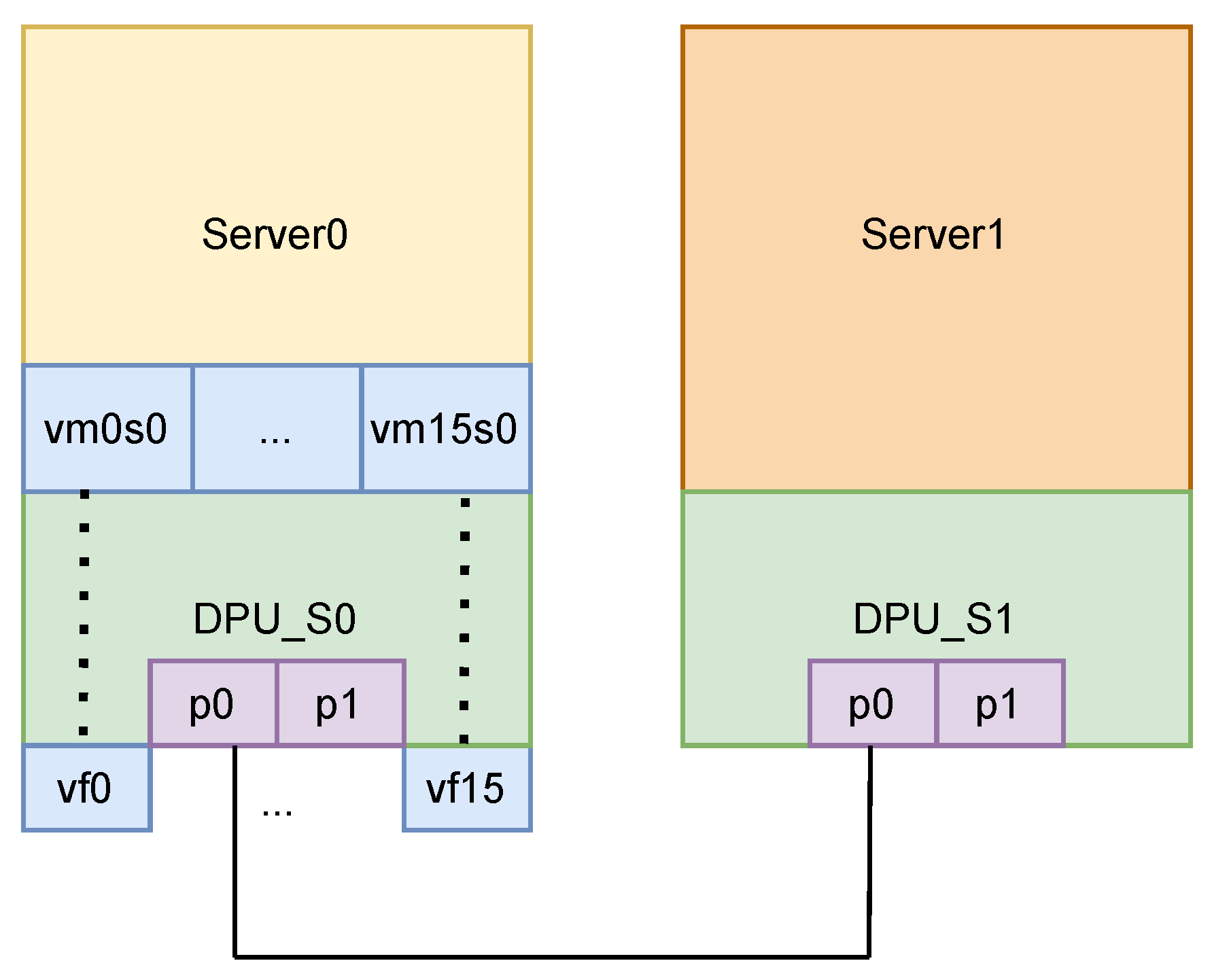
The overview of the experimental setup can be seen in
Figure 5. Server0 hosts 16 VMs and 16 Virtual Functions (VFs), which serve as client systems operating across distinct network slices. Server1 functions as the “server” in this architecture. We detail each component’s implementation and the specific algorithms deployed, demonstrating the successful establishment of quantum-resilient IPsec tunnels across pre-configured network slices. Finally, we evaluate network performance—specifically bandwidth—under multiple experimental scenarios.
These two servers are directly connected through their DPUs on a QSFP112 400 Gbit/s transceiver cable. These servers are basically identical; both have an Intel Xeon Gold 6438M CPU of two 32-core sockets each (64 in total), along with 629 GB of RAM memory. At the same time, they are both equipped with an NVIDIA BlueField-3 DPU [
59], capable of achieving 400 Gbit/s. No switch or intermediate device was used, ensuring that all observed results were attributable solely to the endpoints and the direct link. Each VM is configured with 4 vCPUs and 4 GB of RAM. Both servers ran modern Linux distributions (Ubuntu 22.04) with matching kernel (6.8.0-52-generic), DPU firmware (32.45.1020), and driver versions to eliminate software-induced variability. Each server’s network interface was configured for a jumbo MTU size of 9214 bytes, which is the maximum size supported by the NVIDIA BF-3. We make this design choice in order to maximize throughput by testing large packet sizes (9000B), which is significant when running high-speed TCP and UDP tests, especially for achieving 400 Gbit/s.
We test our configuration by setting our DPUs on both modes of operation. DPU mode and NIC mode are the two operational modes of NVIDIA BlueField-3 DPUs, each defining how the device interacts with the host system and manages network traffic.
6.2. Modes of Operation of the Data Processing Unit
In
DPU mode (also called embedded CPU function ownership, or ECPF mode), the BlueField’s embedded ARM subsystem is fully active and takes ownership of the NIC resources and data path [
60]. In this mode, the ARM cores run their own Linux operating system and act as a trusted management and control layer for the network interface. All network communication to and from the host passes through a virtual switch control plane hosted on the ARM cores. This means that the ARM subsystem can enforce security policies, perform packet inspection or modification, and orchestrate advanced networking features before any traffic reaches the host operating system. The host sees a network interface, but its privileges are limited: it cannot fully control the NIC, and many configuration and management operations must be performed from the ARM side. DPU mode is the default mode of operation for the NVIDIA BlueField-3 DPUs and is particularly suited for environments where advanced network functions, security, and isolation are required. In DPU mode, the data center or cloud administrator can use the ARM OS to load network drivers, reset interfaces, update firmware, implement packet processing pipelines P4/DPL or OvS and manage the overall behavior of the DPU independently of the host. This architecture enables use cases such as secure multi-tenancy, zero-trust networking, and in-line network services like firewalls, encryption, and telemetry, all offloaded from the host CPU and managed in a secure, isolated environment on the DPU itself.
In contrast,
NIC mode configures the BlueField DPU to behave exactly like a traditional Network Interface Card from the perspective of the host system [
60]. In this mode, the embedded ARM cores are not booted, and all management and control of the NIC is handled by the host operating system. The host has full ownership of the NIC’s resources and can perform all configuration, driver loading, and firmware updates directly. NIC mode is designed for scenarios where maximum performance, power efficiency, and simplicity are desired, and where the advanced management and isolation features provided by the ARM subsystem are not required. When the DPU is set in NIC mode, it saves power and improves device performance by disabling the ARM OS, and the host system interacts with the device as it would with any standard network adapter. This mode is especially useful for environments where the primary goal is to leverage BlueField’s hardware acceleration capabilities (such as IPsec or RoCE offloads) without the complexity of an additional management layer.
To comprehensively evaluate PQC-IPsec performance, we test both DPU and NIC modes to quantify the trade-offs between security functionality and hardware acceleration. The comparison directly measures how architectural choices impact real-world post-quantum migration, where DPU mode offers enhanced security control and NIC mode delivers optimal efficiency, simplicity, and out-of-the box performance.
6.3. Architecture
VMs/VFs Configuration. The first component of the architecture involves setting up the virtualized systems and configuring network slicing. Algorithm 1 provides a comprehensive overview of this workflow. We begin by creating 16 VFs. The DPUs are then placed into switchdev mode, which is a crucial step that converts the Physical Function (PF) into a hardware-offloaded switching entity capable of handling packet processing tasks at the hardware level. In this mode, we generate the VFs along with their corresponding “representor” ports. These representor ports act as software interfaces, enabling OvS to interact with and manage the VFs.
The initialization process continues by launching the VMs. We bind the created VFs to the vfio-pci driver [
61] to enable direct passthrough to the VMs. We also use Single Root I/O Virtualization (SR-IOV) [
62]. SRIOV is a foundational technology for hardware-assisted network slicing, enabling direct assignment of physical NIC resources to VMs while ensuring strong isolation between them. By bypassing much of the hypervisor’s software stack, SRIOV delivers near-native I/O performance and reduces the risk of interference between tenants—an essential property for secure, multi-tenant network slicing in 5G and cloud-native environments. By leveraging technologies such as SRIOV and NVIDIA’s virtualization tools, our network slicing implementation assigns a dedicated VF to each VM and binds it to the vfio-pci driver. This approach ensures efficient allocation of network resources and robust isolation between virtual machines, supporting high-performance and secure multi-tenant environments.
| Algorithm 1 VMs-VF Configuration |
- Require:
The script must be executed as a sudoer. - 1:
procedure
Main - 2:
Initialize Configuration: - 3:
Retrieve the system’s hostname to determine specific network settings. Identify the PCI address of the NVIDIA BlueField-3 DPU. Determine the physical network interface name associated with the DPU. - 4:
Manage VF: - 5:
Terminate any running VMs to ensure safe VF reconfiguration. Remove previously created VFs from the DPU. Create a specified number of new VF (e.g., 16 VFs) and assign unique MAC addresses to each VF. - 6:
Configure Switchdev Mode: - 7:
Unbind all VFs from their current driver to prepare them for switchdev mode. Set the DPU to switchdev mode, enabling advanced networking features. Rebind all VFs to their driver after configuring switchdev mode. - 8:
Set Up Network Interfaces: - 9:
Bring up the physical network interface (PF). If the hostname matches a predefined value (e.g., “Server0” or “Server1”), assign an IP address and network configuration based on the hostname. Activate each VF interface to make it ready for use. - 10:
Manage Virtual Machines: - 11:
Start all inactive virtual machines, ensuring they are ready to use the newly created VF. - 12:
Remote Configuration: - 13:
Connect to a remote server (e.g., DPU ARM cores) via SSH and execute commands to configure additional networking features. - 14:
end procedure - 15:
procedure GET_IFACE_BY_PCI(PCI_DEV) - 16:
for each interface related to the PCI device do - 17:
if The interface is not a virtual function then - 18:
Return the physical interface name. - 19:
end if - 20:
end for - 21:
end procedure - 22:
procedure GET_VF_BY_PF(PF_PCI) - 23:
Return a list of PCI addresses corresponding to virtual functions associated with the physical function. - 24:
end procedure
|
This configuration establishes low-latency communication between each VM and the Data Processing Unit (DPU), bypassing the host CPU for data-plane operations—a critical requirement for implementing network slices. When the DPU is set in NIC mode, no further configuration is required. That is, since from the perspective of the host the device acts as an NIC, steering is handled by the device’s FW. However, in DPU mode, incoming and outgoing VM packets are not yet processed correctly; all traffic is dropped due to the absence of logical steering. To resolve this, we configure traffic steering rules on the DPU’s ARM cores.
The final step of this component attaches the DPU’s PF and VF representor ports to an OvS bridge. These representor ports act as software proxies for the VFs, enabling OvS to manage traffic between the VMs and external networks. By leveraging OvS’s programmability, we implement granular control over rules and policies governing each VM’s VF interface. In this way, the
PQC-IPsec implementation as mentioned in Algorithm 2 and
Figure 3 is executed and thus, quantum-resilient communication channel(s) are established between the hosts or the VM(s) and the server host.
| Algorithm 2 Kyber, Dilithium, and IPsec Tunnels Configuration |
- Require:
The script must be executed as a sudoer. - 1:
procedure
Main - 2:
Server Configuration: - 3:
Define the server’s network interface and IP address. - 4:
Clients (VM) Configuration: - 5:
Define the range of the clients’ (VM’) IPs. - 6:
Loop Through Clients’ IPs: - 7:
for each IP address in the specified range do - 8:
Construct the current client IP address. - 9:
Start the server PQC-IPsec script for the server’s IP address in detached mode. - 10:
Wait briefly to ensure the server is initialized. - 11:
Connect to the VM-client machine using SSH. - 12:
Start the VM-client PQC-IPsec script on the remote machine for the current VM-client IP address. - 13:
Wait briefly before proceeding to the next iteration. - 14:
Print a separator line for clarity. - 15:
end for - 16:
Check IPsec State: - 17:
Count and display the number of active IPsec tunnels. - 18:
Display all IPsec policies. - 19:
Print a success message indicating that all servers and clients have been started successfully. - 20:
end procedure
|
Parallel Network Performance Test. To ensure the validity and reproducibility of our results, we carefully orchestrate the execution of iPerf3 (3.19) [
63] instances across all virtual machines. Each VM is treated as an independent client, allowing us to assess the aggregate bandwidth and network behavior under realistic multi-tenant conditions. This approach is particularly important when evaluating PQC-IPsec tunnels, as it reflects the typical deployment scenario where multiple VMs may simultaneously access secure network resources.
To maximize the accuracy of our measurements, we synchronize the start of all iPerf3 clients with a brief delay after establishing SSH connections. This synchronization ensures that the network load is generated as uniformly as possible, minimizing the risk of measurement artifacts due to staggered test initiation.
After the designated test duration, all iPerf3 processes are terminated and SSH sessions are closed, ensuring a clean state for subsequent experiments and preventing interference between runs. Algorithm 3 provides the complete workflow for this evaluation component.
| Algorithm 3 Parallel Network Performance Test Configuration |
- Require:
The script must be executed as a sudoer. - 1:
procedure
Main - 2:
Server Initialization: Start 32 iPerf3 server instances bound to the local server’s IP with sequential port numbering starting. Run all servers in parallel background processes. - 3:
Clients-VM Configuration: - 4:
Define the range of the clients’ (VMs’) IPs. - 5:
Define 2 test ports per VM with sequential port numbering. - 6:
Execute Tests: - 7:
for each VMs’s IP do - 8:
for each test instance index in the range 0 to 1 do - 9:
Calculate unique port number for current test combination. - 10:
Connect to target VM using SSH through Server0. - 11:
Sleep for 2 s for each thread. - 12:
Initiate UDP-based network performance test to specified server IP address and calculated port. - 13:
Run test in background for parallel execution. - 14:
end for - 15:
end for - 16:
Test Parameters: - 17:
Set test duration to 10 s per instance. - 18:
Configure unlimited bandwidth mode for stress testing. - 19:
end procedure
|
Monitoring and logging the output of each iPerf3 instance allows us to collect detailed performance data, including throughput, latency, and any retransmissions or errors encountered during the test. This data is essential for understanding the impact of PQC-IPsec on network performance and for identifying potential bottlenecks or scalability issues. By testing both DPU and NIC modes, we can also compare several trade-offs in order to provide valuable insights for future deployment strategies.
Furthermore, our methodology aligns with best practices for network performance benchmarking, such as using multiple parallel streams when appropriate to fully utilize available hardware resources and to better simulate real-world traffic patterns. This comprehensive approach ensures that our results are robust, relevant, and directly applicable to high-performance, quantum-resilient network environments.
6.4. Methodology
The experimental procedure was shaped to provide a comprehensive comparison of all relevant hardware and software offload options, and to reflect realistic, high-performance data center traffic conditions.
A central focus of the experiment was the integration of post-quantum cryptographic algorithms into the IPsec key exchange and authentication process. Specifically, the Kyber1024 algorithm (for key encapsulation) and Dilithium5 (for digital signatures) were used, reflecting the latest NIST PQC standardization efforts. These algorithms were combined in a hybrid fashion with classical cryptography, ensuring both quantum and classical security. The PQC handshake was used to establish IPsec Security Associations (SAs), and the resulting symmetric keys were then used with AES-GCM for data encryption within the IPsec tunnel. This approach allowed for a realistic assessment of the overhead and performance impact of this system in a high-throughput, low-latency environment.
The experiment was structured to compare three distinct offload modes in NIC mode, and a software-centric mode in DPU mode, for different server–client(s) scenarios. For both of these modes and scenarios, we also provide as a baseline of the actual line-rate performance we achieved. In this case we have an insecure communication channel (no cryptography between the (v)hosts. However, we believe that this baseline is important, as it showcases the added computational/network complexity that gets added into the system. In NIC mode, the DPU’s ARM cores were disabled, and the host system interacted with the DPU as a high-performance Network Interface Card. In NIC mode, the three offload modes tested were (1) no offload, in which all IPsec processing—including encryption, decryption, and ESP encapsulation—was handled by the host CPU; (2) crypto offload, where only the cryptographic operations were offloaded to the DPU hardware, while ESP encapsulation remained in software; and (3) packet offload, where the entire ESP packet processing, including both cryptography and encapsulation, was performed in the DPU hardware, making the offload completely transparent to the host. Each of these modes was tested with both TCP and UDP traffic, using the maximum MTU size, and with a variety of parallel streams to simulate real-world traffic patterns.
For each test, the host system’s IPsec SAs and policies were configured using the Linux iproute2-6.11.0 utility, with the appropriate offload flags (no offload, crypto offload, packet offload) set to control the behavior of the DPU. The PQC handshake and key management were orchestrated using custom scripts. Traffic generation was performed using iperf3, with careful attention paid to the number of parallel connections, the packet size, and the duration of each test. Throughput was measured as reported by iperf3, while CPU utilization was monitored using mpstat and system resource monitors. Hardware offload activity was confirmed by querying DPU counters via ethtool-S and inspecting sysfs/debugfs entries for ESP and IPsec statistics.
In DPU mode, the BlueField-3’s ARM cores were activated and ran a dedicated Linux OS. In this mode, the IPsec SAs and policies were managed directly by the host, but the key distinction was that all cryptographic and encapsulation operations were handled in software on the ARM cores, without the benefit of the same granular out-of-the-box hardware offload options with firmware steering available in NIC mode. We implemented the packet processing procedure in OvS with hardware offload in order to accelerate general packet forwarding, but IPsec itself remained a software process on the (v)hosts. The same PQC handshake and key management procedures were used, and traffic was again generated and measured using iperf3 with identical parameters to those used in NIC mode. This allowed for a direct comparison of the performance and resource utilization between the two operational modes.
Throughout the experiment, particular care was taken to validate that traffic was indeed being encrypted and decrypted as expected. This was accomplished by capturing packets both on the host (to observe plaintext in packet offload mode) and, when necessary, on the wire (to confirm ESP encapsulation). The correctness of the PQC handshake and hybrid key establishment was verified using test vectors and logs, ensuring that the cryptographic protocols were functioning as intended. Troubleshooting steps included adjusting system resource limits, verifying offload flags, and monitoring for any packet drops or errors reported by the DPU hardware.
The results of the experiment provided a detailed comparison of the throughput for each offload mode and operational configuration. In NIC mode, packet offload delivered efficient network performance, while crypto offload provided a balance of performance and flexibility. No offload mode, as expected, imposed the most limited throughput. In DPU mode, the use of OvS hardware offload improved general packet processing dramatically and surpassed the performance of out-of-the-box FW steering performance of the offload options of NIC mode. That is, due to the high impact that packet processing has on the network performance for such workloads and traffic patterns, HW steering with the offloaded OvS implementation achieves near line-rate throughput. We provide results for both TCP and UDP, and it becomes prominent that UDP performs better. We carry out an exhaustive analysis of our results in the Evaluation Section.
This methodology, by systematically varying only one parameter at a time and maintaining a tightly controlled test environment, ensured that the observed performance differences could be confidently attributed to the offload mode, cryptographic configuration, and operational mode of the BlueField-3 DPU. The use of direct server-to-server connection, maximum MTU, and modern PQC algorithms provided a forward-looking assessment of how next-generation secure data center networks will perform under quantum-resistant security requirements. We then used these host-to-host results as a baseline for evaluating the performance of the multi-tenant environment of the various slices/VMs that act as clients. The findings inform both the practical deployment of PQC-IPsec in high-performance environments and the design of future hardware offload architectures.
7. Evaluation
In this section we present the results of our experiments. We categorize them into two distinct sections; NIC mode and DPU mode of operation of the NVIDIA BlueField-3 DPU. We evaluate our system implementation for both TCP and UDP traffic. Packet sizes are of 9000 B and the MTU is set at 9214 B (the maximum for this hardware). We test two configurations: host-to-host and the other server’s VF(VM)-to-host. However, we acknowledge a limitation of our research work in terms of VF-to-host experiments on NIC mode, due to device limitations regarding opening more than 4 to 6 connections simultaneously. This challenge is beyond the scope of this work. The presented results are the average throughput in Gbit/s of 10 runs, for 10 s each. The deviation of these results was relatively negligible (around 0.1%), and is thus left out of the figures.
Each figure has the same traffic parameters. Nevertheless, we use various iPerf3 instances/configuration (number of cores, number of ports, etc.) depending on the scenario and the transport layer protocols used, but the same for all the results of each figure. We thus present the relevant results to the best performing configuration that we chose in order to achieve line-rate performance (400 Gbit/s) with iPerf3. That alone poses a great challenge on its own and is beyond the scope of this work. Additionally, the server-side of iPerf3 was always bound to specific NUMA nodes to ensure that CPU, memory, and network resources are optimally aligned [
64].
To evaluate the impact of large MTU and jumbo frames on network performance, we tune both the network interface and the system’s kernel parameters. We firstly increase the receive (RX) and transmit (TX) ring buffer sizes of the specified network interface. By setting both to 8192, the DPU can handle a larger number of packets in hardware before passing them to the OS, which is especially important when transmitting large frames such as jumbo frames. This helps reduce packet drops and improves throughput when using large MTU values.
The second set of tuning adjusts system-wide socket buffer sizes and memory limits using sysctl. We tuned the system to support high-throughput networking by significantly increasing the available memory and buffer sizes for network communications. Specifically, we raised the maximum send and receive buffer sizes to 512 MB each, ensuring the kernel can handle very large volumes of data. For TCP, we set the minimum send and receive buffers to 4 kB and 8.7 kB, respectively, with maximums also at 512 MB, allowing the system to adapt buffer sizes as needed while supporting massive data transfers. For UDP, we established minimum send and receive buffers at 32 kBs each and allocated up to about 30.9 MB of memory for all UDP sockets, with a warning threshold at roughly 20.6 MB. Together, these adjustments enable the system to efficiently manage large packet sizes and high-speed traffic typical in environments using jumbo frames.
Setting the MTU to 9214 B enables jumbo frames, which are Ethernet frames larger than the standard 1500 B. Jumbo frames reduce protocol overhead, lower CPU utilization, and increase throughput by allowing more user data to be sent in each packet. This is particularly beneficial in high-performance environments such as storage networks, virtualization, and data centers.
7.1. PQC Computational Evaluation
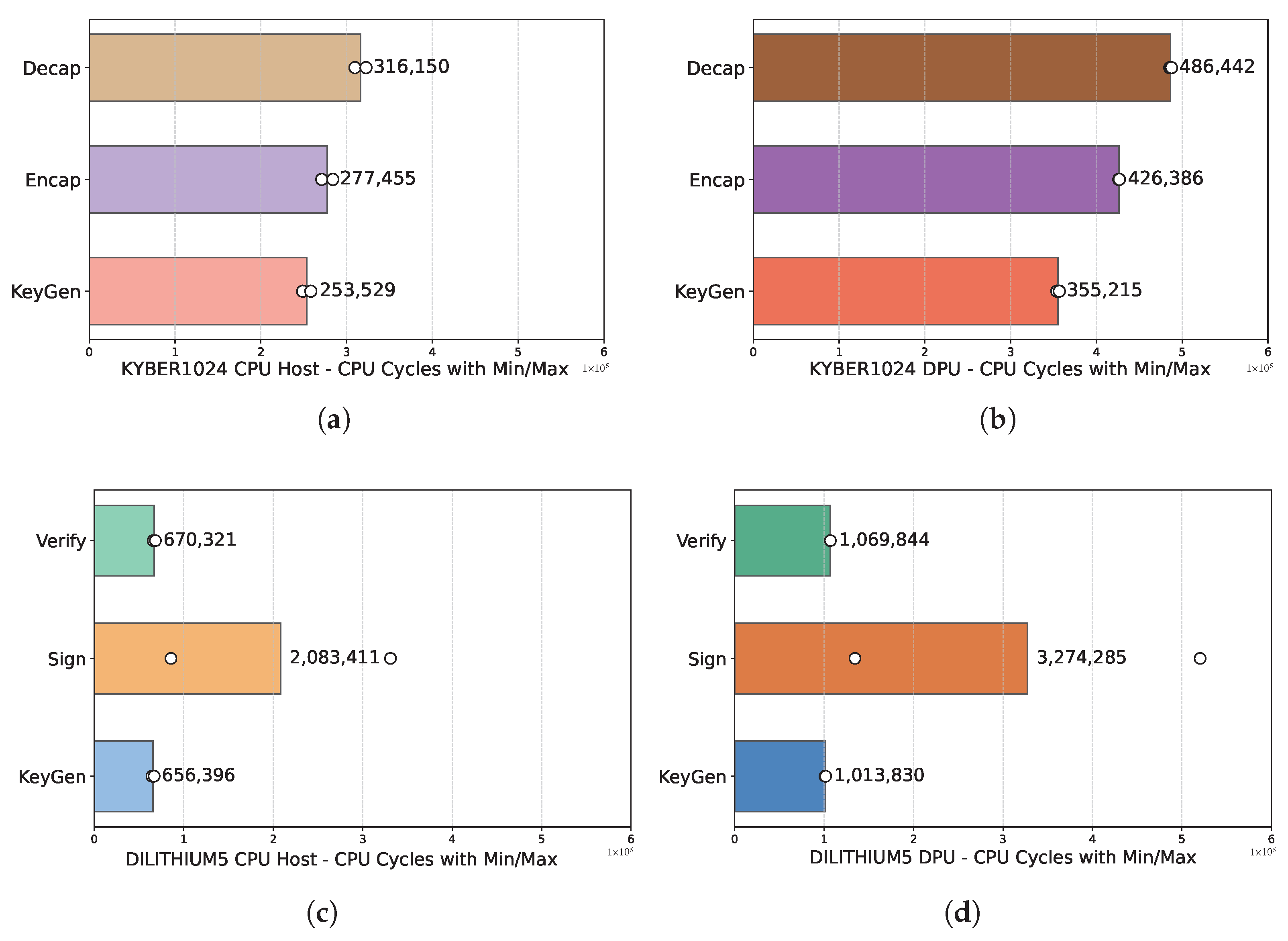
Before we dive into the network performance of our implementation, we first evaluate the performance of Kyber1024 (ML-KEM) and Dilithium5 (ML-DSA) of both the host CPU (x86) clocked at 3900 MHz and the ARM cores of the DPU, which are clocked at 2135 MHz. As previously mentioned in the Other Related Work Section, the research community has conducted an exhaustive analysis in this area. However, by providing this evaluation, we provide insights for the overall performance of our framework more extensively. We characterize the performance of PQC on these two hardware devices by breaking down the key exchange (ML-KEM) and the signature (ML-DSA) into three main key-block algorithms and we note S for Server and C for Client, depending on which party executes them.
| ML-KEM: | - Decapsulation | S | | ML-DSA: | - Verify | C |
| - Encapsulation | C | | - Sign | S |
| - Key Generation | S | | - Key Generation | C |
For the purposes of this work, we measure the single core performance of each device in clock cycles for 100,000 executions of these cryptographic algorithms. We provide the results of this experiment in
Figure 6.
Comparing the single-core performance of ML-KEM and ML-DSA on the ARM cores of the DPU and the host x86 CPU, is inherently non-straightforward due to substantial architectural differences between these CPUs. ARM cores employ an RISC approach characterized by simpler instructions and greater energy efficiency, while x86 CPUs utilize a CISC architecture with richer, more complex instructions capable of performing multiple operations per instruction. We used the x86 CPU (with or without virtualization overhead) for the PQC algorithms in QRoNS. The results presented in the next sections reflect the network performance, after the PQC-IPsec tunnels have been established.
7.2. NIC Mode
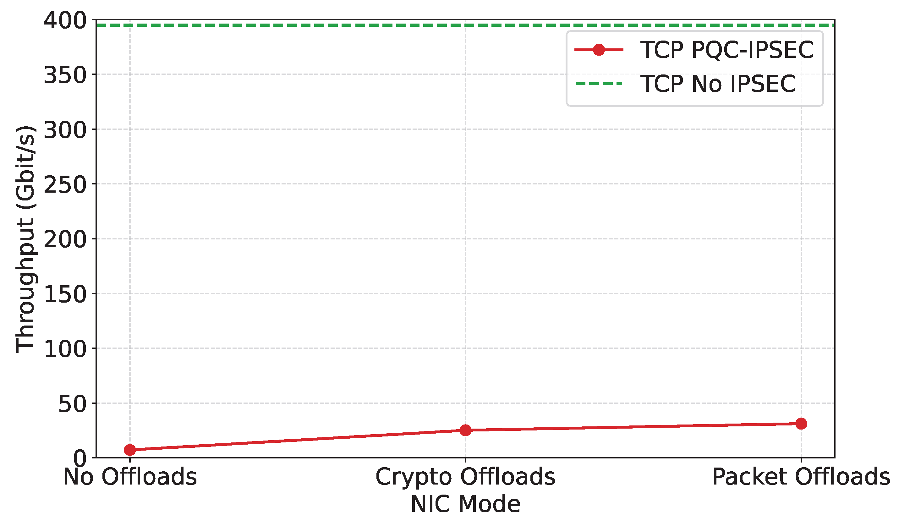
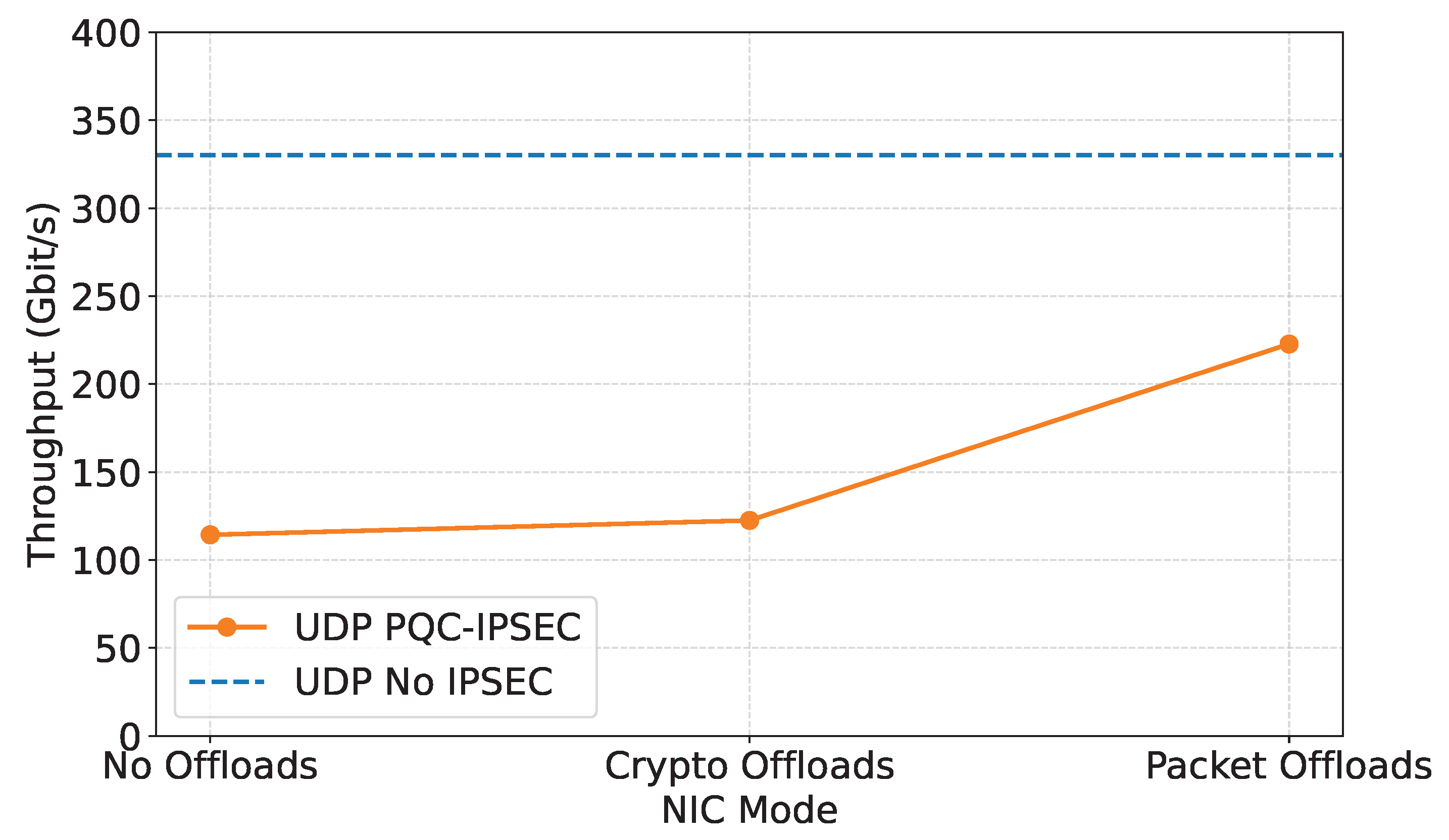
In this section, we present the results for the NIC mode of operation in line plots. For both cases, the dashed lines (baseline) present the achieved line-rate performance of this configuration with no cryptography. Note that we only showcase results for host-to-host performance, due to device limitations in regard to our virtualized systems.
TCP performance takes a great hit in this scenario, as seen in
Figure 7. We can see that for packet offload, we achieve 31.18 Gbit/s or 7.9% of our baseline line-rate of 394.81 Gbit/s. However, compared to no offloads with 7.2 Gbit/s, throughput is increased by a factor of 4.331 and to crypto offload with 25.14 Gbit/s, by a factor of 1.24. To address this, we analyzed traffic with wireshark [
65] and captured with tcpdump [
66] for all modes and found that data packets (after the three-way handshake) varied in size, acknowledging the extra size of the encapsulation and the necessary encryption data that would be added to the packets. That was not the case for the unencrypted communication channel of the baseline (no cryptography or IPsec).
In contrast, UDP performance shows significant throughput improvement compared to the unencrypted baseline and between the several offload modes, as seen in
Figure 8. We can see that no offloads with 114.33 Gbit/s or 34.63% of the line-rate with 330.16 Gbit/s and crypto offload with 122.49 Gbit/s or 37.1% of the line-rate have relatively similar performance. The benefits become evident for the packet offload mode with 222.78 Gbit/s or 64.48% of the line-rate. Compared to no offload, this is a 1.95X improvement and to crypto offload a 1.82X improvement.
7.3. DPU Mode
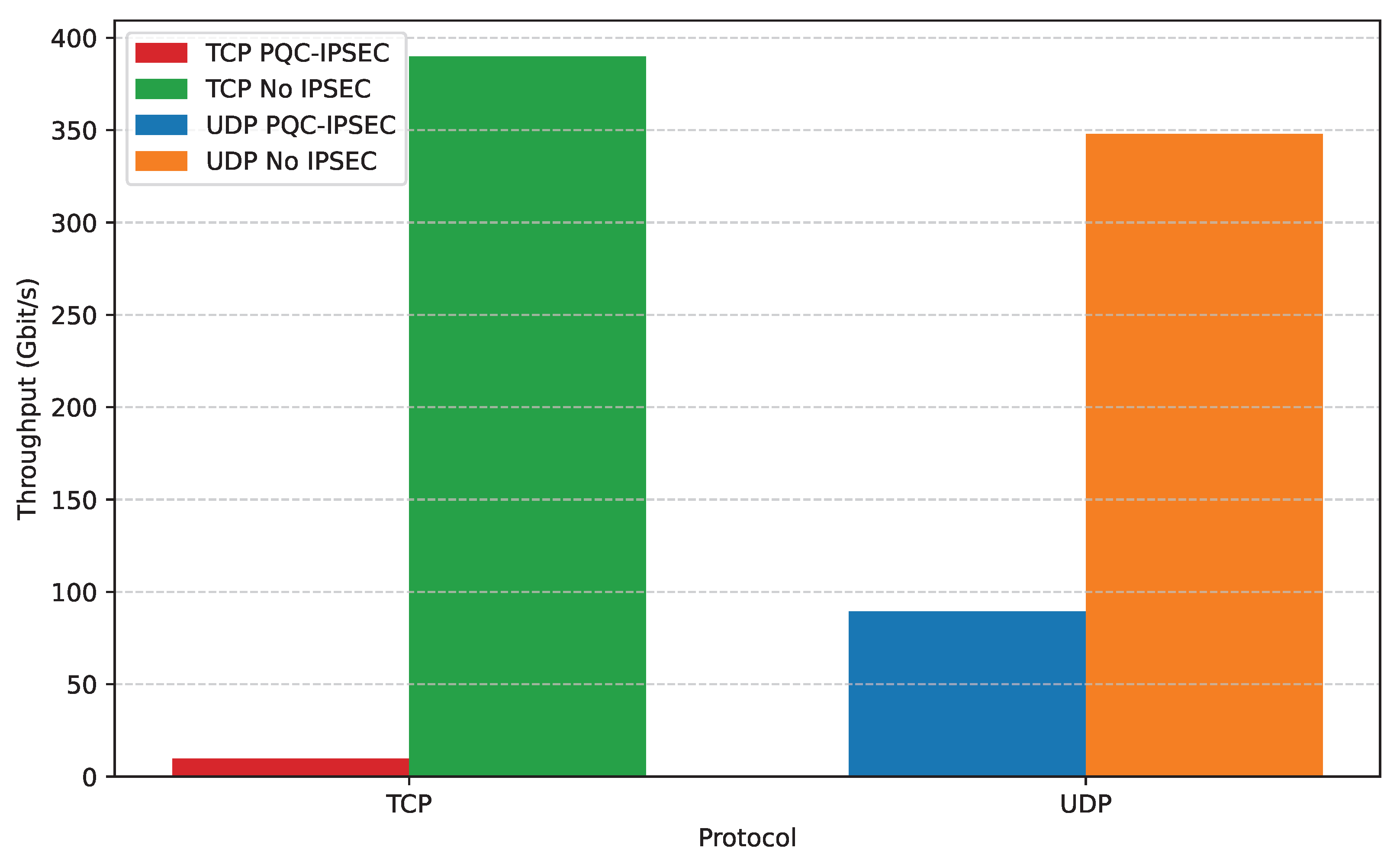
We continue by evaluating the DPU mode of operation and presenting the results in bar and line plots. Similarly, the dashed lines on the line plots (baseline) present the achieved line-rate performance for the host-to-host configuration with no cryptography. Additionally, the bar plot’s X axis is the transport layer protocol and the line-rate baseline for each is the righter-most bar, accordingly. Note that in the DPU mode of operation, offloads in policies and states through iproute2 do not exist. We have two types of results: the unencrypted line’s performance and PQC-IPsec throughput performance with no offloads. We present the results of the VMs/network slices. To be able to draw conclusions from these results, we also provided measurements of unencrypted performance on the line, depending on the number of slices that take part in this communication, so that we can quantify the achieved throughput over the the virtualization, computational, and communication costs. Finally, we implemented the packet processing of this experiment in OvS on the ARM cores with HW offload and steering to efficiently steer the packets of the hosts, as well as of the VMs from Server0 to Server1.
In
Figure 9, we provide the host-to-host bar plot for TCP and UDP for PQC-IPsec and for the line-rate baseline performance. PQC-IPsec over TCP performs poorly, achieving only 9.64 Gbit/s compared to the unencrypted line-rate baseline of 389.85 Gbit/s. This is a mere 2.47% utilization of the line-rate performance. On the contrary, UDP showcases tolerable performance, achieving 89.49 Gbit/s compared to the 347.93 Gbit/s baseline or 25.72% utilization of the line-rate. We will now present the real performance benefits of QRoNS, which can be especially observed for the VFs-to-Host configuration.
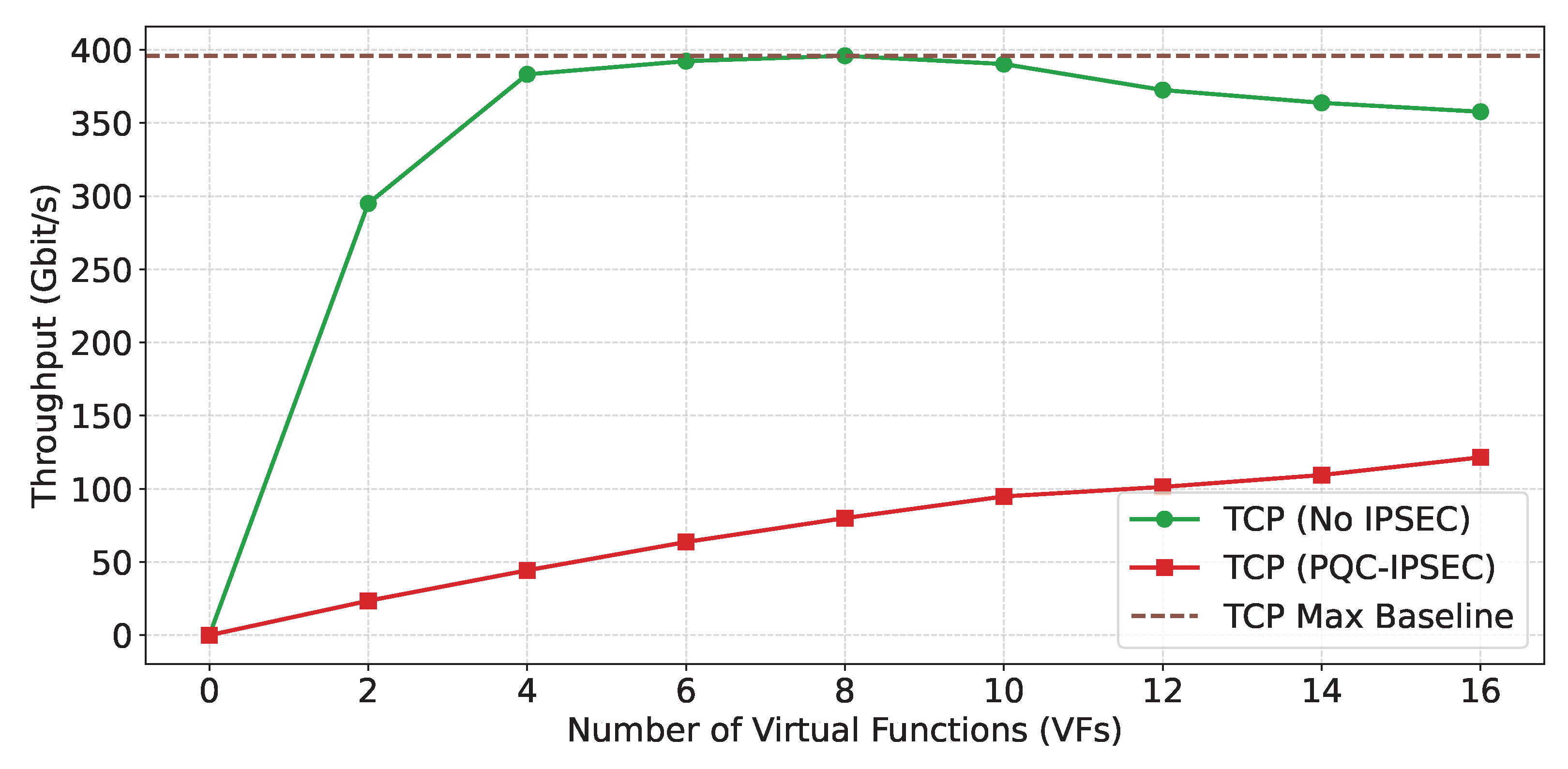
In
Figure 10 and
Figure 11 we provide the line-plot of the results for the VFs-to-host configuration over TCP and UDP, accordingly.
TCP Results
2 VMs: PQC-IPsec achieves 23.51 Gbit/s, while the line performance is 295.00 Gbit/s. The achieved utilization is 7.97% of the line rate.
4 VMs: PQC-IPsec achieves 44.32 Gbit/s, while the line performance is 383.23 Gbit/s. The achieved utilization is 11.57% of the line rate.
6 VMs: PQC-IPsec achieves 63.67 Gbit/s, while the line performance is 392.26 Gbit/s. The achieved utilization is 16.24% of the line rate.
8 VMs: PQC-IPsec achieves 80.03 Gbit/s, while the line performance is 395.92 Gbit/s. The achieved utilization is 20.21% of the line rate.
10 VMs: PQC-IPsec achieves 94.82 Gbit/s, while the line performance is 390.27 Gbit/s. The achieved utilization is 24.30% of the line-rate.
12 VMs: PQC-IPsec achieves 101.32 Gbit/s, while the line performance is 372.52 Gbit/s. The achieved utilization is 27.20% of the line ate.
14 VMs: PQC-IPsec achieves 109.43 Gbit/s, while the line performance is 363.76 Gbit/s. The achieved utilization is 30.07% of the line rate.
16 VMs: PQC-IPsec achieves 121.51 Gbit/s, while the line performance is 357.68 Gbit/s. The achieved utilization is 33.98% of the line rate.
UDP Results
2 VMs: PQC-IPsec achieves 56.03 Gbit/s, while the line performance is 60.95 Gbit/s. The achieved utilization is 91.93% of the line rate.
4 VMs: PQC-IPsec achieves 110.61 Gbit/s, while the line performance is 145.39 Gbit/s. The achieved utilization is 76.08% of the line rate.
6 VMs: PQC-IPsec achieves 176.16 Gbit/s, while the line performance is 237.93 Gbit/s. The achieved utilization is 74.04% of the line rate.
8 VMs: PQC-IPsec achieves 220.84 Gbit/s, while the line performance is 303.89 Gbit/s. The achieved utilization is 74.04% of the line rate.
10 VMs: PQC-IPsec achieves 271.29 Gbit/s, while the line performance is 359.55 Gbit/s. The achieved utilization is 75.45% of the line rate.
12 VMs: PQC-IPsec achieves 327.33 Gbit/s, while the line performance is 390.54 Gbit/s. The achieved utilization is 83.82% of the line rate.
14 VMs: PQC-IPsec achieves 384.18 Gbit/s, while the line performance is 393.90 Gbit/s. The achieved utilization is 97.53% of the line rate.
16 VMs: PQC-IPsec achieves 392.98 Gbit/s, while the line performance is 393.07 Gbit/s. The achieved utilization is 99.99% of the line rate.
7.4. Analysis of the Results
When comparing DPU mode to NIC mode, the results highlight the trade-offs between security offloading and raw performance. In NIC mode, the average TCP throughput across three different PQC-IPsec configurations ranges from 7.20 Gbit/s to 31.18 Gbit/s, with the highest configuration reaching 7.89% of the line rate (394.81 Gbit/s), while UDP averages 153.20 Gbit/s (46.40% of line rate). This suggests that, for TCP, NIC mode can offer modestly better performance than DPU mode, but both remain limited by the protocol’s inherent overhead. For UDP, however, NIC mode delivers nearly double the throughput of DPU mode, indicating that direct hardware access and reduced software stack involvement are particularly beneficial for connectionless/stateless traffic.
These findings illustrate that the choice between the DPU and NIC modes hinges on the specific requirements of the workload and the desired balance between security and performance. DPU mode excels at providing advanced security features, such as isolated policy enforcement and robust encryption, but this comes at the cost of significant throughput penalties for both TCP and UDP, especially at higher scales. NIC mode, on the other hand, is better suited for maximizing raw throughput and minimizing latency, particularly for workloads that are less sensitive to the advanced security and virtualization features offered by the DPU.
Ultimately, the data highlights that, while quantum-resilient security is feasible in both DPU and NIC modes, protocol choice remains the dominant factor in achievable performance. UDP consistently outperforms TCP in both operational modes, approaching or even exceeding the line rate in DPU mode at higher VM counts, while TCP struggles to break single-digit percentage utilization in most scenarios. This suggests that future optimizations should focus on hardware acceleration for cryptographic operations, protocol stack improvements, and workload-specific tuning to bridge the performance gap, especially for connection-oriented applications requiring both high throughput and robust security.
In DPU mode, the host-to-host performance for PQC-IPsec-protected connections reveals a contrast between TCP and UDP protocols. For TCP, the average throughput with PQC-IPsec reaches only 9.64 Gbit/s, which represents a mere 2.47% of the line-rate capacity (389.85 Gbit/s). This low utilization underscores the heavy computational overhead that quantum-resilient encryption imposes on connection-oriented traffic (TCP) when processed by the DPU’s ARM cores and software stack. In contrast, UDP achieves a much higher average throughput of 89.49 Gbit/s, or 25.72% of the line rate, demonstrating that stateless, lightweight protocols can better leverage available hardware acceleration and bypass some of the bottlenecks inherent in TCP’s design.
The experimental results of the DPU mode VF-to-host configuration reveal a clear distinction in performance between TCP and UDP when using PQC-IPsec in a virtualized environment. For TCP, the achieved throughput remains a relatively small fraction of the line rate, starting at just 8% with 2 VMs and gradually increasing to 34% with 16 VMs. This progression reflects the significant overhead imposed by TCP’s connection-oriented nature and the additional cryptographic processing required for quantum-resilient security. In contrast, UDP demonstrates much higher efficiency, with utilization rates consistently above 70% for most VM counts and ultimately reaching 99.9% at 16 VMs. This stark difference underscores how UDP’s stateless and lightweight design, combined with effective hardware offloading, enables it to approach line-rate performance even under the demands of PQC-IPsec. These findings highlight that, while quantum-resilient security is feasible for both protocols, UDP is far better suited for high-throughput, latency-sensitive applications in virtualized and sliced network environments. The results also suggest that further hardware acceleration and protocol optimization could help close the gap for TCP, but the inherent protocol overhead will likely remain a limiting factor.
