1. Introduction
In 5G mobile communication, Cloud Radio Access Network (C-RAN) is a potential cellular communication network due to its high energy efficiency (EE) [
1,
2,
3]. Compared to the conventional co-located antenna assembly containing baseband units (BBUs) and radio stations, the BBUs are located at the centre in C-RAN, which are attached to distributed remote radio heads (RRHs) through front-haul links [
2,
4]. In C-RAN, the transmission path between antennas and users is decreased, and a significant improvement of EE can be achieved. Massive multi-input multi-output (M-MIMO) will be able to connect with many users. Therefore, by offering high power gain, M-MIMO reduces the transmit power, which leads to increased SE as well as EE [
5]. Hence, with a huge population of RRHs in a cell with a reduced transmission power, the efficiency of the network will be considerably improved. Moreover, linking each RRH with M-MIMO can achieve greater EE [
6,
7,
8]. This raises the complexity gains of convectional MIMOs [
1,
6] and diminishes the interference between users’ access points [
1]. In recent years, with green information technology, EE has attracted more attention. Thus, the resource allocation for EE maximization has attracted considerable attention [
7]. The main purposes of C-RAN networks are to improve the EE, SE, and achievable rate of users. It can be performed by locating a huge number of RRH antennas, stated as M-MIMO, and achieving higher SE to 5G [
4,
8]. This balances the complexity gain of conventional MIMOs and eases the interference amongst users [
1,
9]. For example, the EE optimization problem related to the set of user numbers, antennas, and transmit power has been reported several times [
7,
8].
In recent years, a significant rise in the deployment of advanced wireless networks, i.e., C-RAN, has been noticed in FD mode. In the FD C-RAN, the RHHs may perform self-interference (SI) cancellation, and then send received signals to the BBU. Many literature reports on FD radio systems have been successfully applied in recent communication networks, attaining almost a two-fold gain in EE over the traditional half-duplex (HD) mode [
5,
9,
10,
11]. In FD C-RAN, users are randomly placed in the cell and connected to RRHs with different access paths. Some nearest RRHs significantly contribute to users’ communication, but others do not. Hence, for a given user, instead of being served by all RRHs, a few nearest RRH neighbours could be used to serve a single user [
4]. Meanwhile, when all RRHs take part in the transmission and each user is associated with one RRH, the power consumed by front-haul links and the antenna circuitry might be severe, which subsequently leads to degradation of the EE. Although C-RAN offers strong storage resources, it still has low limitations because of the limited capacity of both front-haul links [
6]. To overcome these drawbacks, traffic over front-haul links should be considered while planning the optimization approach. Additionally, the energy consumption (EC) of massive MIMO can be knowingly reduced if we improve the EE-SE trade-off [
3,
6]. User association, specifically connecting users to a base station (BS), significantly distracts the network EE. In this circumstance, the problem of user association is critical, which makes the analysis more challenging. Therefore, the association of RRHs for each user is a concern for C-RAN. To overcome this issue, various algorithms have been proposed based on different planning metrics [
4,
12,
13]. It is also worth mentioning that though there exist several research activities on single-objective optimization problems in C-RAN communication, multi-objective resource allocation is still scarce in the literature to manage various conflicting objectives [
1,
14,
15,
16,
17]. The resource allocation for finding the relation between EE and SE in a mono-cell network is investigated through a common algorithm using the weighted sum method since the objective function is convex [
14,
18,
19]. Motivated by this fact, for the future 5G wireless networks, MOO is a promising method.
MOO has been studied in wireless communications. In [
14,
19,
20,
21,
22], the authors studied an MOO resource allocation scheme for a multi-user environment considering imperfect channel state information (CSI) for maintaining the balance between transmit powers in downlink and uplink mode. They also demonstrated with simulation results the trade-offs between the conflicting objectives and the robustness of the system. In [
23,
24], the authors apply it for cognitive radio networks for optimizing SE and EE. The authors of [
25] presented an optimization technique for the data signal and energy transfer trade-off in multi-user MIMO systems in downlink mode by applying weighted sum and majorization–minimization (MM) methods. In [
26], the authors studied the robust design for multi-user multi-input single-output networks in downlink mode by using the Tchebycheff method.
There are several benefits of -constraint method over the conventional method. (1) In linear problems, the application weight sum method to the feasible region provides a corner region with efficient extreme solutions. Thus, the weighting method requires a lot of iteration and a combination of weights while -constraint exploits almost every iteration to obtain a new and more efficient solution. (2) The weight sum method does not provide an unsupported efficient solution in non-linear MOO problems while -constraint method does. (3) The major benefit of the -constraint method includes managing numerous generated solutions by playing with the number of parameters in each objective function range, while it is not possible in the weighting method. The weaknesses of the -constraint method are choosing a perfect value for the epsilon vector, and demanding a large number space size for iterations to calculate the weighting method.
We express the problem of optimization of EE within the structure of user associations in C-RAN networks. We consider an FD-enabled C-RAN, where transmitted and received wireless signals are handled simultaneously, as a disruptive solution for improving EE. The proposed network contains downlink transmission for users served by RRHs equipped with massive MIMO, and each user should be associated with one RRH. We adopted two different methods here. First, the ε-constraint method [
26,
27] converts the MOO problem into an equivalent SOO problem [
14] and solves it by the MM method [
28,
29,
30]. In this paper, we take advantage of MOO by using the
-constraint method to show the relationship between SE and EE. Then, by employing the MM approach, which transforms a difference-of-convex (DC) function into a sequence of convex function problems with the change in the variable and relaxation method. The MM method can be applied by two approaches. In the first approach, we search for a substitute function that analyzes the objective function. More precisely, first, the substitute function maximizes the optimization problem to a constant, and then it minimizes to the optimal solution point. The key contributions of this work are highlighted:
To maximize the EE problem, we propose an MOO framework. We obtained the optimal Pareto front of the proposed MOO through tackling the EE-SE trade-off problem. To tackle the non-convexity and NP-hard nature of the EE-SE trade-off, we did it in two steps.
In the first stage, we determined that SOO is a non-convex problem by employing the -constraint method that is solved by iterative algorithms.
Then, we solve the objective function by the MM method, which converts a DC problem (difference in convex functions) into a sequence of convex problems with a change in variable to achieve the optimal solution of the Pareto front.
Numerical results determine that the proposed algorithm can give a better and faster converging limit. Simulation results compare the EE-SE trade-off. We show the proofs of the Pareto optimal of our MOO algorithm and evaluate its performance with varying maximum power conditions.
2. System Model
Consider a C-RAN network (
Figure 1), with
J cells,
N number of RRHs, and
K number of users distributed in individual cells. Each user uses a single antenna mobile device to reduce complexity. The designated users and in the
jth cell are scheduled for uplink (UL) and downlink (DL) transmissions simultaneously. Therefore, mobile users
are equipped
with antennas. The effective number of antennas in the
jth cell is therefore expressed as
. The channel matrix between the RRHs in the
jth cell and the
kth user in the
mth antenna can be denoted as
where
,
and
[
10]. We assume path loss and small-scale fading coefficients are given by
and
, respectively. The
indicates the space between the
kth user (
jth cell) and the
nth RRH (
jth cell). The symbols
a, α, and
represent path loss gain, path loss exponent, and
channel vectors, which are independently and identically distributed and expressed in the form of a complex Gaussian distribution CN(0,1).
Similar to [
10,
11], we apply minimum mean-square error (MMSE) method to know channel vector information at BBU can be expressed as
where
and
is
received pilot signal. The large-scale fading between the
nth RRH in the
jth cell and the
kth user in the
mth cell is given by
. The additive white Gaussian noise
of the receiver is given as
. Thus, the channel vector can be restated as
where
.
We use the maximum ratio transmission (MRT) method and so that the user association matrix
in the
jth cell is given by
The transmitted signal for DL case in the
jth cell is expressed as
where
is the beamforming vector
is transmitted data symbol. Then, we can express the received signal in the
jth cell of the
kth user as
where
is the noise of receiver at the
kth user given by
~ CN(0,σ).
represents the transmitted signal user
i in the
jth cell in UL phase,
denotes transmit power sent from UL user
i in the
jth cell,
is the transmit data signal from UL
ith user, and the
j-th cell is the term representing the channel coefficients between the DL user
k in the
mth cell and the UL user
i in the
jth cell [
12].
Now we can write the signal-to-interference noise ratio (SINR) of the
kth user in the
mth cell at DL mode as
Here,
is the transmitted power from the RRHs to each user in the
m-th cell, and
denotes the active number of antennas in the
m-th cell at each RRH. Therefore, the achievable rate in the DL in the mth cell is given by
In this network, we assumed that all users share the same bandwidth, so the bandwidth is neglected. Thus, the throughput or the system SE is given by
Then, we express the total power consumed by the network in the
mth cell as
where
represent the circuit power consumed per antenna, which does not depend upon the transmit power.
denotes the static power consumed by RRH and BBU. Thus, the system EE is expressed as a fraction of the achievable sum rate divided and consumed power, and can be given by
4. Problem Analysis
Here, we apply the ε-constraint method to achieve the Pareto optimal for (16), in which we set
f1 as the main objective function and
f2 takes care of the constraints [
26,
27]. Meanwhile, (7) i.e., depending on the system’s transmit power, it shows the influence of energy consumption is higher on the network as compared to that of system throughput. After applying the ε-constraint method, the MOO problem (10) would become
Since the ε-constraint scheme yields a set of optimal solutions [
27], the solution achieved by problem (16) covers the solution of problem (11). The importance of the ε-constraint method greatly depends upon the formulation of (16) and the solution of (11). This fact turns ε into a complex parameter for arranging the objective functions f1 and f2 in (15) that helps to find EE trade-offs between them. However, the non-convex constraint sets of (14) still remain a challenging task. Therefore, to tackle the non-convex nature of the feasible set in (16), we propose an iterative algorithm approach to demonstrate the EE maximization in the following sections.
4.1. Simplify Constraints of Continuous Variable Product to Resolve the Non-Convexity
To solve for the non-convexity of problem (11), we first tackle the multiplication variables in constraints C2. Here, it implies that if the user association is not allocated to user
k in cell
j, the user’s transmit power is zero. According to this clarification, we reaffirm C2 as
The feasible region defined by (19) and (20) matches that of constraint C2. Thus, substituting C2 with C2′ and C2″ without any change in the feasible set of (17) and using equivalent convex forms of C1 and C2 [
28]. Further, in (19), if users are not allowed to transmit over their respective cell (if
), the SINR and the users’ data rate over cells unallocated to them would be zero. Therefore, (7) is equivalently written as
For simplicity, we can ignore
from (8) and rewrite the objective (18) as an affine or real function, which is given by
4.2. The Resolution of Binary Constraints
Another challenging task is to solve (18) due to the integer variables. These binary variables make (18) a mixed-integer non-linear program (MINLP), and solving (18) becomes a tedious job within an acceptable period. To tackle this problem, we apply a method similar to [
29] and restate constraint C3 as follows:
We further removed constraint C3” and in its place added it as a penalty function consisting of a weight parameter
to the objective function. The weighting factor
is used to reproach the objective function (when
is not binary). In this scenario, the equivalent presentation of the original MOO is
4.3. Convex Approximation—Majorization and Minimization
Massive MIMO systems have a large number of antenna arrays that produce a huge volume of data. Therefore, the handling of such data with conventional algorithms is problematic for solving the MOO user association. It is ideal to use algorithms that exploit the MM method for the concerned energy-efficient user association problem. The objective function can be restated as follows
where
and
.
There are two convex functions,
and
, in (25). As we know, the difference between two convex functions is not necessarily convex. Thus, we find an approximate convex function
by applying the MM technique [
29,
30]. In the MM technique, a sequence of surrogate functions is defined that mimics the original non-convex function using Taylor’s approximation. Therefore, for a given iteration number i, we will have
Now, we can replace the left-hand side of Equation (27) with
. Also, we know that the difference between a convex and linear function is always convex. Thus, the problem of non-convexity can be resolved. Finally, the resultant convex optimization problem can be written as
We apply the penalty term within the MM framework to linearize the non-convex constraints. Specifically, the binary constraint on the association variable is relaxed and penalized by introducing a weighted term, which is then integrated into the objective function. This allows the algorithm to iteratively approximate the binary behaviour while maintaining tractable convexity in each iteration.
4.4. Consider 4 Cases for Choosing
Case I: If ε = 0, (28) minimizes the energy consumption.
Case II: If ε = Rmax, (28) could be the result of the throughput maximization problem.
Case III: If ε ≥ Rmax, (28) the result could be infeasible.
Case IV: If 0 < ε < Rmax, (28) would be a MOO problem.
According to the above cases, we can see that the optimization problem (27) is very sensitive to the value of ε. Thus, the priority of the objective functions can be manipulated by controlling the ε-parameter. In other words, for high values of ε, more importance is put on throughput maximization, while for smaller values of
ε, more importance is put on minimizing power consumption. Further, for a particular ε, a trade-off between throughput and power consumption could result in maximum EE. To determine this particular value of ε, we aim to maximize EE and the proposed algorithm is brief in Algorithm 1.
| Algorithm 1. Energy-Efficient User Association Algorithm |
Initialize and i = 1, step size δ Obtain Rmax by solving problem (28). while (ω ≤ 1) Set ω = ω + δ. Compute using (29). Initialize t = 0, penalty factor Repeat Update using (26) Solve problem (27) and obtain Set t = t + 1. Until convergence or t = tmax Set End
|
From the above cases (I) and (II), the maximum possible system throughput without making (27) infeasible is R
max. We can obtain the throughput value by cracking the following optimization problem
which is again the optimization problem of throughput maximization. After solving (28), the maximum limit R
max can be estimated, which indicates the boundary of infeasibility of the problem. We can see now, the optimization problem (27) is convex and simple to solve. To obtain local optimal solutions of problem (17), we employ the DC programming [
31,
32] to start iteration, and then we will get a local optimal solution of the optimization problem in the process [
33].
4.5. Fixing ε for EE Maximization
The optimum trade-offs of throughput and energy consumption are given by a specific ε. To maximize network
η, the specific value of ε corresponds to the maximum
to
ratio. To know the specific value of ε, we express it as
where ω > 0 in the range of (0, 1). Depending on ω, the ratio of
and
will vary. Conversely, for a precise ε, the above ratio of throughput and power reaches a maximum limit. Therefore, by examining different values of ω
to
ratio, we can eventually reach a point where maximum EE is achieved.
5. Simulation Results
This section presents a comparison of the various user association algorithms. The simulations were conducted using MATLAB R2022a on a system. This environment supports the complexity of the MM and ε-constraint-based optimization algorithms. The simulation parameters are shown in
Table 1.
We assume a seven-cell network with a central cell surrounded by six interfering cells. Here, each cell is equipped with
N = 10 RRH and
K = 20 users. The simulation parameters of power consumption based on [
4] are set as P
c = 0.82 W, and
= 9 W. We consider noise power parameter σ
2 = −120 dBm and path loss exponent α = 4. The large-scale fading model is based on [
34].
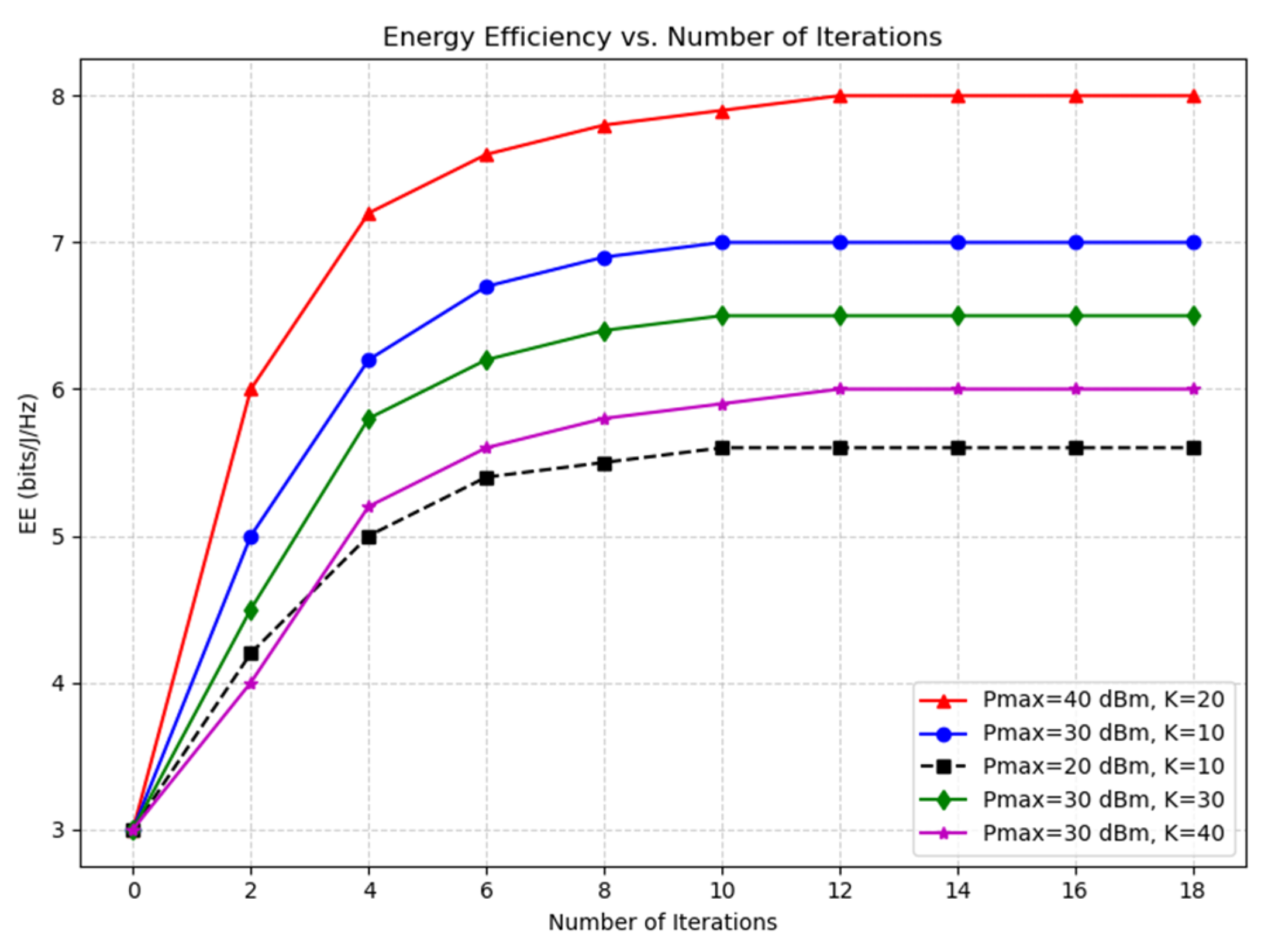
Figure 2 displays the system EE versus the iteration number. The EE achieved through the proposed algorithm was compared for the different users (
K = 20 and
K = 10) and transmit power constraints. As shown in
Figure 2, under identical transmit power constraints, the proposed algorithm converges faster when the number of users K = 10, achieving stability within 10 iterations, compared to the slower convergence for K = 20. As seen from the figure, with fewer users (K = 10), the system achieves higher EE compared to scenarios with more users (K = 40), as resource sharing becomes more efficient. Overall, the figure confirms that the algorithm converges quickly and demonstrates clear trade-offs between transmit power, user load, and achievable energy efficiency. These comparisons validate the observation that smaller user numbers lead to quicker convergence.
The proposed algorithm converges at 10 iterations when there are fewer users (K = 10). Here, for K = 10, = 20 dBm and EE is 6.1 bits/J/Hz, and for K = 10, = 30 dBm and EE is 6.7 bits/J/Hz. When is low, the proposed algorithm converges quickly within 10 iterations. When the increases and K = 20, the interference from other users increases progressively too. Thus, a higher EE is achieved at a high density of users, K = 20, and transmit power ( = 40 dBm) at 12 iterations.
The main remark is that, in all three cases, the EE performances first increase and then remain unchanged when increases. When is small, the corresponding constraints have a strong impact on EE performances. However, when sufficiently is large, the other constraints lead to the performance. So, further increasing the transmit power budget for the network brings additional EE benefits. Compared to all three cases, = 40 dBm achieves good EE performances.
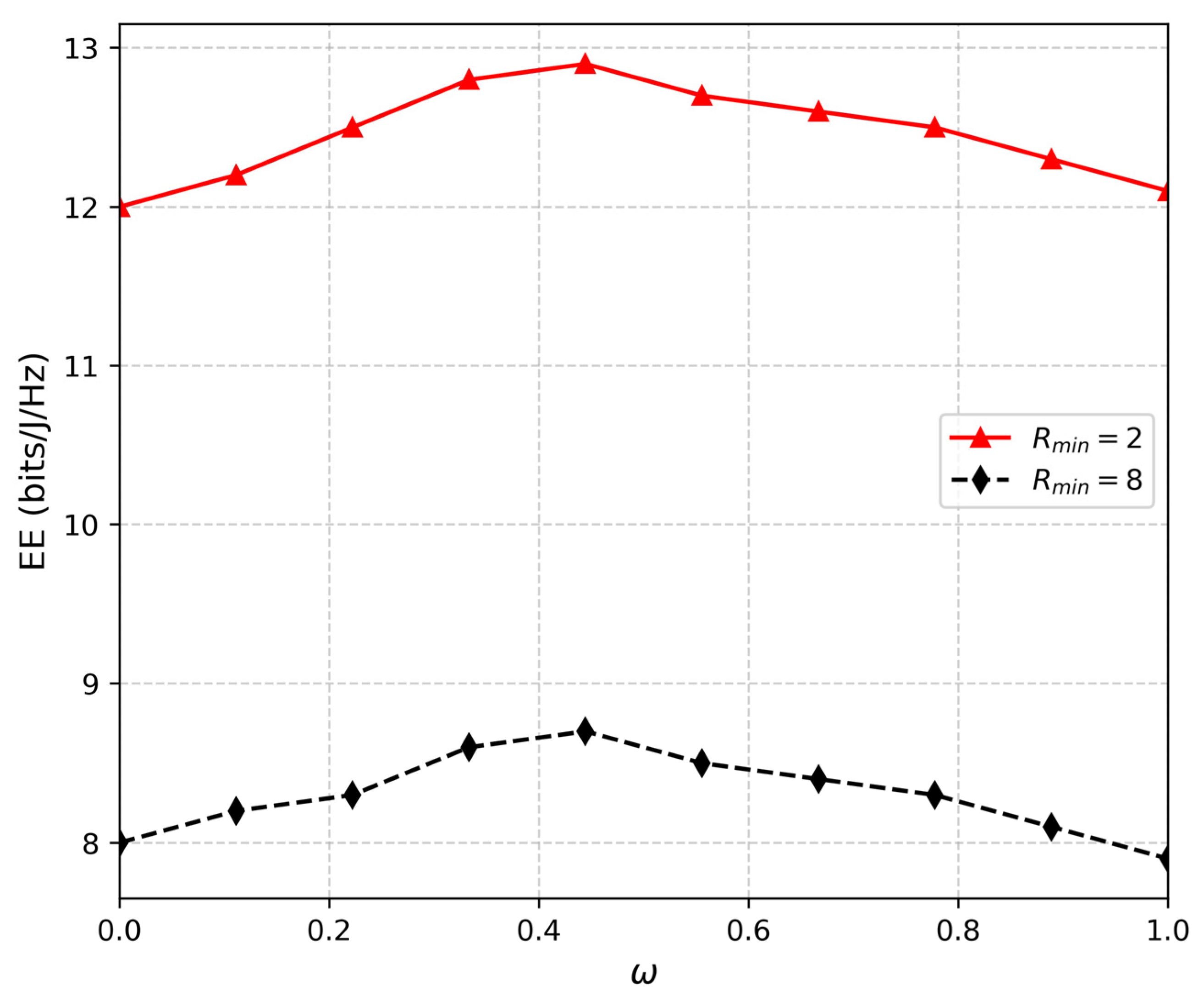
Figure 3 illustrates the EE against different ω values for
= 2 and
= 8 cases. The EE peak at ω = 0.4 results from an optimal trade-off between power allocation and data rate satisfaction; beyond this value, increased interference to meet higher QoS demands leads to EE degradation, which provides valuable insights for practical network design. As expected, the EE of the network decreases beyond ω = 0.4 for both
= 2 and
= 8 cases. When
= 2 and ω is equal to 0.4, the EE of the network extends its maximum values, EE = 12.7 bits/J/Hz. Consequently, if we increase ω to 0.6, 0.7, 0.8, 0.9, and 1.0, the EE decreases in order: 12.28, 12.25, 12.2, 12.0, and 11.7-bits/J/Hz, respectively. Additionally, we can say that when we increase the weight parameter ω, the EE decreases. It means that beyond a maximum ω, the interference term increases progressively due to improved data rate requirements, and hence the degradation in the EE of the system occurs when
increases. This is practical since extra power should be given to users to satisfy the QoS constraints.
From
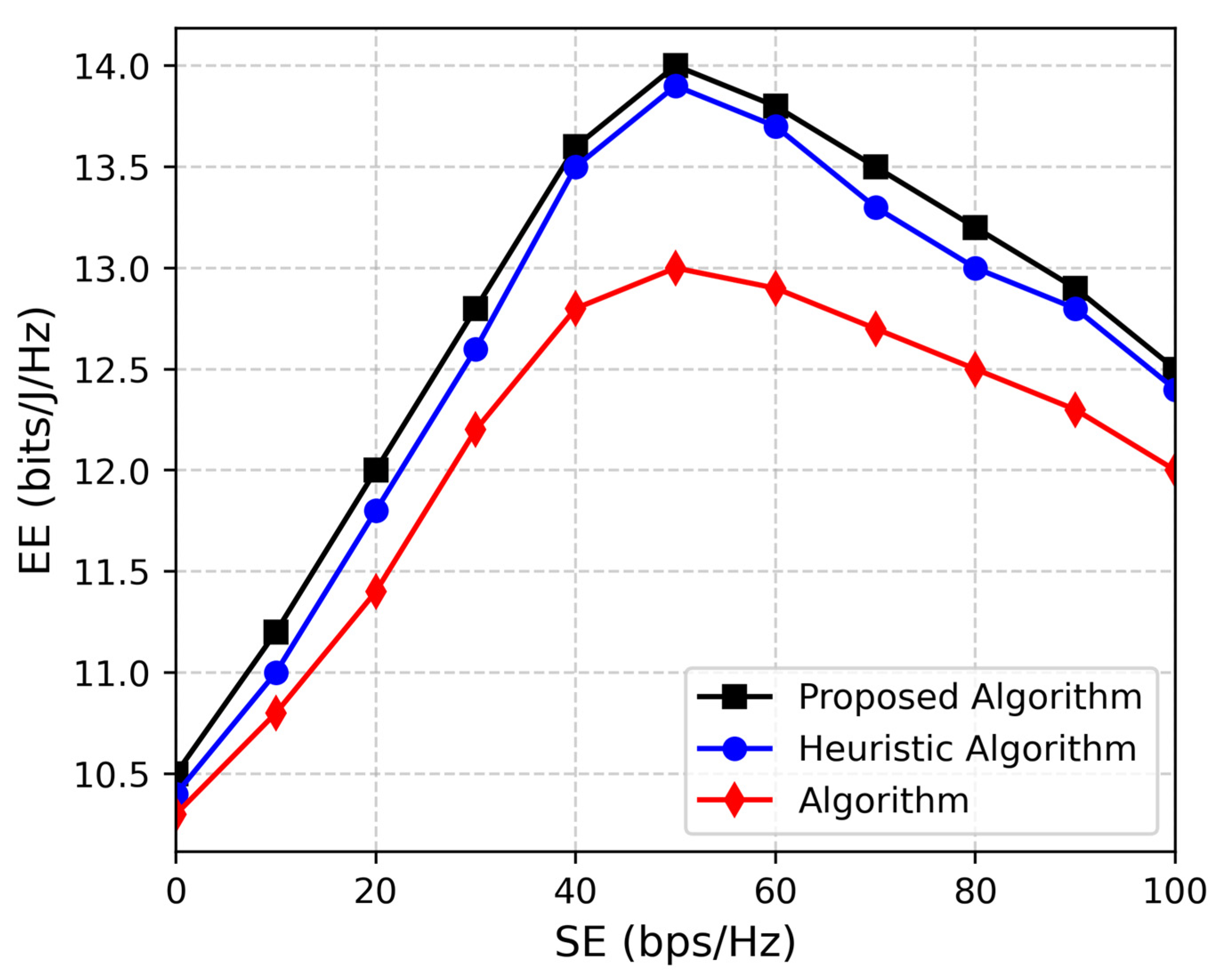
Figure 4, it can be perceived that the system EE increases as we increase the number of users, which specifies that it consumes less power to achieve SE for an increasing number of users. The main reason is attributed to the increased multi-user diversity, which causes an increase in gain. Due to the complexity and large number of antennas employed in the C-RAN network, the EE decrease with SE after a certain value [
34]. We also compare the algorithm in [
27], where a unified approach for EE-SE trade-off in point-to-point wireless communications is derived. We should also note that even though in [
21], EE decrease as SE increases. Meanwhile, in our MOO algorithm, we reaffirmed the problem targeting at minimizing power consumption; additionally, we equate our method with a heuristic algorithm. Consequently, the EE of the C-RAN network is decreased. When users decrease, the network is flooded with the traffic load, which gives enhanced EE.
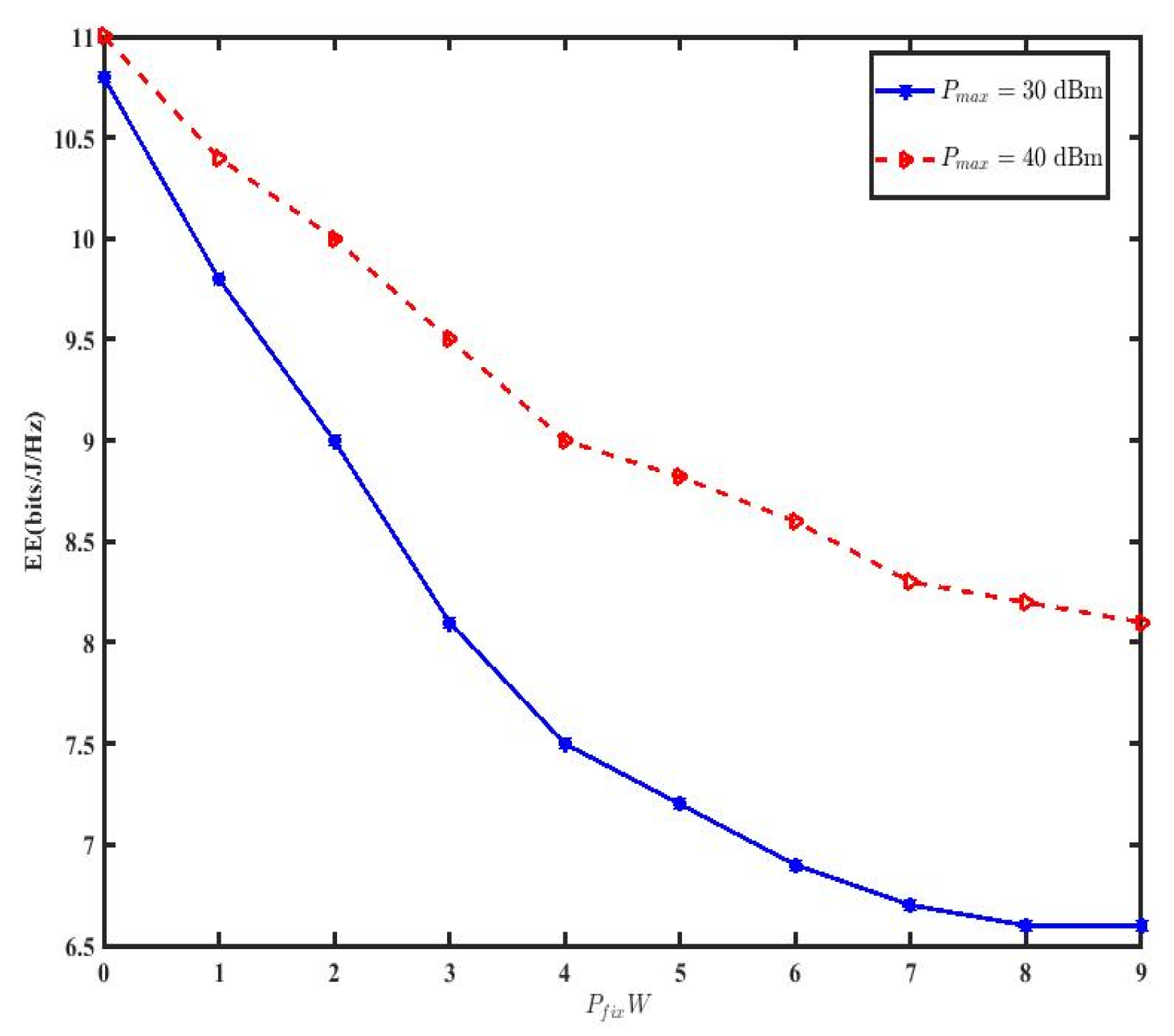
Figure 5 demonstrates the EE performance against
for different transmit power P. The EE drops quickly with a smaller value of
= 30 dBm since
dominates the overall power consumption of each user in this case [
4]. The figure also illustrates that EE decreased with an increasing value of
. Hence, the C-RAN network has a low EE. However, our MOO algorithm shows better performance when P
max = 40 dBm compared to the others.
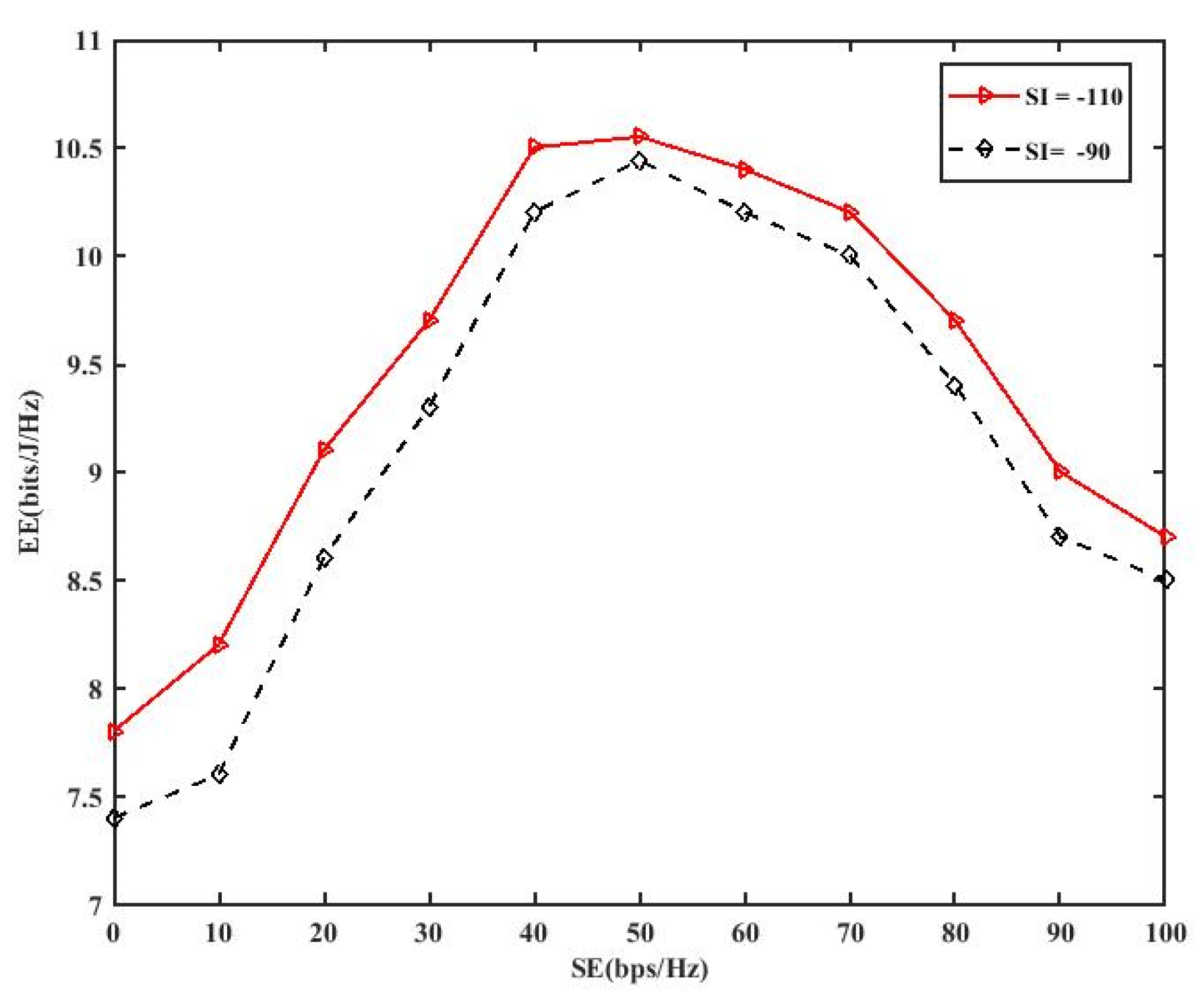
Figure 6 shows the EE- SE trade-off. We can perceive that as the throughput increases, EE also rises, but sharply decreases beyond a maximum. As throughput is a part of transmission power, a progressive increase in system throughput might cause larger power consumption as well. The maximum power consumption goes beyond SE, and the whole EE declines.
We also notice that the trade-off section falls as the value of the SI cancellation factors becomes lower. The explanation for this is forthright, and it is due to the small SI cancellation factors consuming extra power, which results in a lowering of the performance of SE as well as EE.
Figure 7 illustrates the role of weight parameters on system EE. This parameter aims to penalize the weight of the parameter in (27). It would increase the throughput of users and decrease power consumption. As the weight parameter increases, each RRH is allocated to one user, and the value would be either 0 or 1.
Consequently, this would reduce the EE. However, after the penalty parameter reaches 105, EE converges and remains unchanged to further increase in weight parameter. This is because when the weight parameter is appropriately large, the penalty parameter could converge to 0, and further raising its value could become negligible.
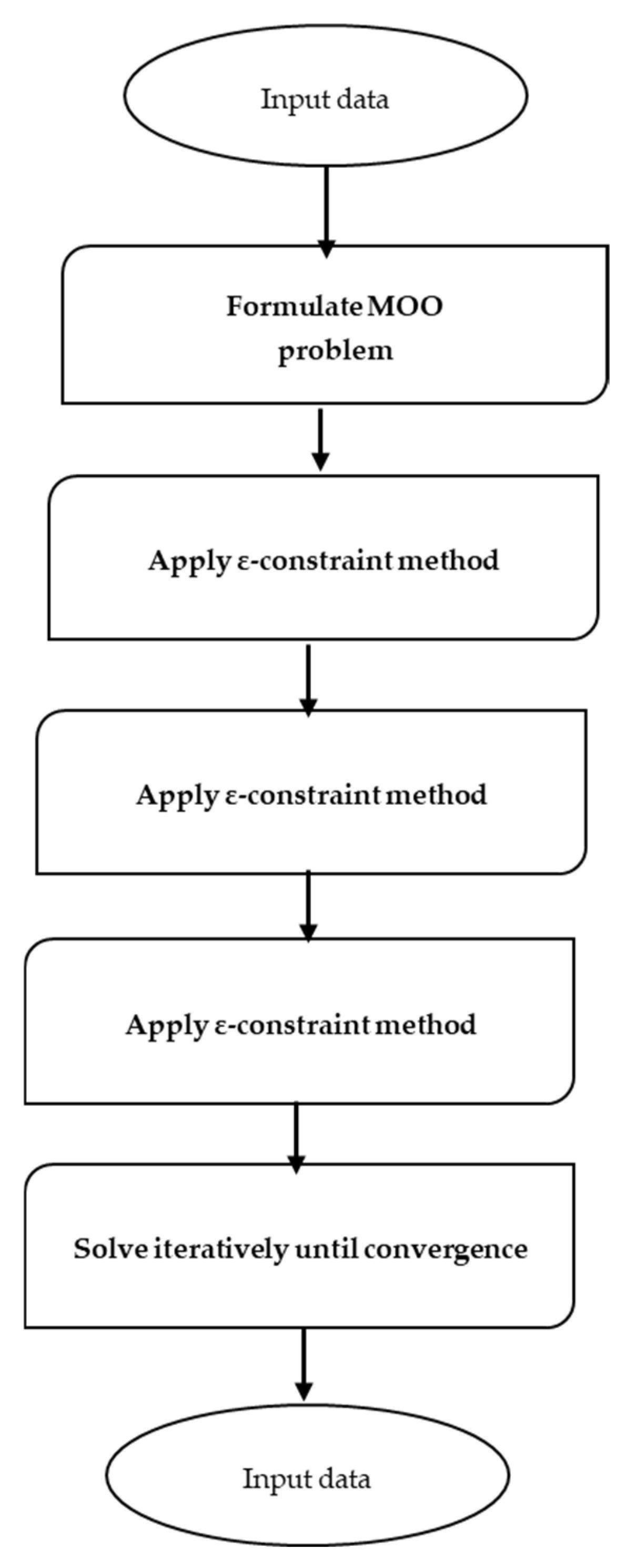
Flowchart of the proposed energy-efficient multi-objective optimization method, showing the steps from problem formulation to obtaining the Pareto-optimal user association shown in
Figure 8.

