Article

Real-Time Technique for Semiconductor Material Parameter Measurement Under Continuous Neutron Irradiation with High Integral Fluence

by
Ivan S. Vasil’evskii
1,
Aleksey N. Klochkov
1,*,
Pavel V. Nekrasov
1,
Aleksander N. Vinichenko
1,
Nikolay I. Kargin
1,
Almas Yskakov
2,3,
Maksim V. Bulavin
2,
Aleksey V. Galushko
2,
Askhat Bekbayev
2,3,4,*,
Bagdaulet Mukhametuly
2,3,4,
Elmira Myrzabekova
2,3,4,
Nurdaulet Shegebayev
3,4,
Dana Kulikbayeva
3,4,
Rassim Nurulin
3,4,
Aru Nurkasova
2,3 and
Ruslan Baitugulov
3
1
Institute of Nanoengineering in Electronics, Spintronics and Photonics, National Research Nuclear University “MEPhI”, Kashirskoe Highway 31, 115409 Moscow, Russia
2
Joint Institute for Nuclear Research, Joliot-Curie Str. 6, 141980 Dubna, Russia
3
Institute of Nuclear Physics, 1 Ibragimov Street, Almaty 050032, Kazakhstan
4
Faculty of Physics and Technology, Al-Farabi Kazakh National University, 71 Al-Farabi Ave., Almaty 050040, Kazakhstan
*
Authors to whom correspondence should be addressed.
Electronics 2025, 14(19), 3802; https://doi.org/10.3390/electronics14193802
Submission received: 26 August 2025 / Revised: 19 September 2025 / Accepted: 23 September 2025 / Published: 25 September 2025
(This article belongs to the Special Issue Radiation Effects on Advanced Electronic Devices and Circuits)

Abstract

The degradation of the electronic properties of semiconductor materials and electronic devices under neutron irradiation is a critical issue for the development of electronic systems intended for use in nuclear and thermonuclear energy facilities. This study presents a methodology for real-time measurement of the electrical parameters of semiconductor structures during neutron irradiation in a high-flux reactor environment. A specially designed irradiation fixture with an electrical measurement system was developed and implemented at the WWR-K research reactor. The system enables simultaneous measurement of electrical conductivity and the Hall effect, with automatic temperature control and remote data acquisition. The sealed fixture, equipped with radiation-resistant wiring and a temperature control, allows for continuous measurement of remote material properties at neutron fluences exceeding 1018 cm−2, eliminating the limitations associated with post-irradiation handling of radioactive samples. The technique was successfully applied to the two different InGaAs-based heterostructures, revealing distinct mechanisms of radiation-induced modification: degradation of mobility and carrier concentration in the InGaAs quantum well structure on GaAs substrate, and transmutation-induced doping effects in the heterostructure on InP substrate. The developed methodology provides a reliable platform for evaluating radiation resistance and optimizing materials for magnetic sensors and electronic components designed for high-radiation environments.

1. Introduction

The study of ionizing radiation’s effects on electronic devices and semiconductor materials remains highly relevant and increasingly important due to the growing use of electronics in extreme environments with high levels of ionizing radiation [1,2,3]. Common examples include electronics for spacecraft and satellite communications and control systems for charged-particle accelerators and nuclear power facilities. A notable application is the control system of TOKAMAK fusion reactors [4]. The dynamic magnetic confinement of plasma in such facilities requires diagnostic systems equipped with a network of magnetic field sensors capable of operating under extremely high radiation loads. The estimated lifetime neutron fluence in the area of magnetic field sensors for ITER is around F = 1018 cm−2, while for the DEMO reactor it is projected to be several orders of magnitude higher, i.e., F = 1022 cm−2 [5]. Selecting appropriate materials for magnetic sensors intended to operate in such radiation-intense environments remains a critical engineering challenge [6]. Recent studies on perovskite solar cells highlight the growing demand for the comprehensive stability evaluation of materials under simultaneous stressors (radiation, temperature, electrical bias) [7].
Research into radiation-resistant materials involves investigating the behavior of different classes of materials, including semiconductors and optical and dielectric materials, with respect to their electrical, optical, and structural properties under radiation exposure [8,9]. Conventional silicon-based devices exhibit limited neutron radiation tolerance, with significant degradation of their electrophysical properties observed at fluences as low as 1014 cm−2. GaAs-based Hall sensors demonstrate improved radiation resistance, maintaining stable performance beyond fluences of 1015–1016 cm−2 [10]. Generally, the onset of substantial radiation-induced damage in semiconductor Hall sensors is observed within the neutron fluence range of 1016–1018 cm−2 [11,12,13]. Neutron irradiation of GaAs and AlGaAs can induce transmutation doping at relatively low thermal neutron fluences [14,15]. However, at higher fluences, the electron concentration tends to decrease, eventually leading to a transition toward dielectric behavior [16,17]. Among the most radiation-resistant semiconductors, InSb and InAs have shown stable sensor functionality up to neutron fluences of 2 × 1018 cm−2 [6,18,19,20]. Neutron capture by indium atoms leads to transmutation into tin, which acts as n-type dopant in these semiconductors [21]. As a result, indium-based semiconductors retain electrical conductivity due to transmutation-induced doping.
In addition to semiconductors, highly conductive materials are being explored as potential sensing elements in Hall-effect devices for steady-state magnetic field measurements. Metals such as gold, molybdenum, tantalum, and copper exhibit high electrical property stability under ionizing radiation and elevated temperatures. However, their sensitivity is significantly lower compared to that of semiconductor-based sensors [22]. Therefore, materials with lower carrier concentrations—such as semimetals (e.g., antimony and bismuth)—have recently been proposed [6,23,24,25], showing enhanced Hall sensitivity. Low-dimensional materials such as graphene [26,27] and semiconductor quantum heterostructures [28,29,30,31] are also under investigation as promising alternatives to bulk conductive films for sensor applications.
The problem of evaluating the radiation resistance of electronic devices and materials is approached using several methodologies. One widely used method involves post-irradiation analysis of materials after a certain cooling period [32,33]. However, a major drawback of this method is the activation of samples and their holders due to nuclear transmutation reactions, which lead to the formation of radioactive isotopes [21]. The deactivation period required for irradiated samples to reach safe handling conditions can extend over several years, delaying their laboratory processing and characterization. Consequently, most research groups are constrained to moderate neutron fluences in the range of 1014–1015 cm−2 [29,34,35]. Typically, samples are irradiated in a sealed capsule [26] and performance measurements are carried out only after the decay of most of the short-lived isotopes [28]. This approach is relatively limited, as it allows for the assessment of only the final state of the sample. During the cooling period, however, additional changes may occur, such as the partial annealing of radiation-induced structural defects even at room temperature [36]. Moreover, post-irradiation thermal treatments—such as high-temperature processing for metal deposition and contact formation—can significantly modify the material’s properties [30,37]. For example, in [26], thermal treatment partially restored the electron mobility and carrier concentration in neutron-irradiated samples of various materials, including graphene and InSb.
A more effective approach to investigate intrinsic changes in device or material properties under high neutron fluence is to use a real-time measurement technique that enables in situ, continuous data acquisition during irradiation in a nuclear reactor environment [10]. This method allows for systematic monitoring of radiation-induced degradation as a function of accumulated dose, without being constrained by the safety limitations typically associated with high-fluence post-irradiation handling. Samples are positioned within the reactor’s irradiation zone, while electrical characterization is performed remotely via shielded connections. After exposure, the samples can be transferred directly to a holding pool or long-term storage facility without requiring direct operator contact. To date, only a few research groups have successfully implemented such complex systems due to the numerous technical challenges involved—such as ensuring reliable electrical insulation, enabling precise magnetic field application, and other instrumentation difficulties originating from intense reactor irradiation [10,19].
The fundamental electrical properties of semiconductor materials—such as resistivity, carrier concentration, and mobility—can be evaluated through measurements of electrical conductivity and the Hall effect. However, most radiation studies have focused on the performance of complete electronic devices and ignore the underlying changes in the intrinsic properties of the semiconductor materials [34].
The objective of this study is to develop and implement a real-time in situ measurement technique for monitoring radiation-induced modifications in the electronic properties of materials. Exposure to high-energy irradiation leads to the formation of structural defects in in the crystal lattice, which alter charge carrier concentration, mobility, and resistance. These parameters can be accurately determined through conductivity and Hall effect measurements under an applied magnetic field. The proposed approach involves the development of a methodology for remote real-time characterization in the process of continuous neutron fluence accumulation. For real-time testing, the samples were mounted inside a developed irradiation fixture and positioned in a high-flux neutron channel of a research reactor. The measurement system enabled continuous monitoring of material properties at specified time intervals without interrupting the irradiation process. We have applied the technique by investigating the electron transport properties of the two different InGaAs-based quantum well heterostructures under continuous neutron irradiation.

2. Materials and Methods

2.1. Experimental System

The experimental setup was designed to measure the electrical characteristics of semiconductor materials and electronic devices under continuous neutron irradiation in channel K-23 of the WWR-K research reactor (Institute of Nuclear Physics, Almaty, Republic of Kazakhstan). At the reactor maximum power of 6 MW, the total neutron flux density at the sample location is 4.95·1011 cm−2s−1. The neutron fluence in the investigated channel was evaluated by a computational approach in the MCNP6 software (version 6.2) environment. The assessment was performed by integrating the spectral distribution of the neutron flux across the entire energy range. The neutron flux values were derived from numerical neutron transport simulations of the reactor core using Monte Carlo-based computational codes. Input parameters included the geometrical characteristics of the channel, the composition and density of the moderator material, and the core configuration. The resulting fluence was obtained by time-integration of the neutron flux density over the energy spectrum. This methodology enables the estimation of fluence while accounting for the spatial–energy distribution of the neutron field, thereby providing sufficient accuracy in the absence of experimental monitor measurements. Future work is planned to incorporate monitor samples in order to determine the neutron fluence through direct experimental methods [38]. The energy distribution of the neutron flux is presented in Table 1, additional details about the spectrum can be found in [39].
A key feature of the setup is the capability for real-time measurement of material parameters directly within the reactor channel during irradiation. This approach enables the direct assessment of dose-dependent behavior, enhances measurement accuracy, and reduces the overall experiment duration by allowing repeated measurements on the same samples. The samples are positioned in a 5 m long vertical channel near the reactor core, as shown in the schematic diagram in Figure 1. Since the vertical channel of the WWR-K research reactor is filled with water as a coolant, all samples, together with the necessary accessories (thermistor, solenoid), are placed in a waterproof, sealed capsule to prevent electrical short circuits during measurements. Most structural elements of the capsule are made of aluminum alloys to minimize post-irradiation radioactivity. The flanges are sealed using indium gaskets. The electronic system responsible for measuring the electrical parameters of the samples is located in a radiation-safe area near the reactor. The capsule is connected to the measuring system via signal and power cables, which are insulated with radiation-resistant fiberglass and housed inside a vertical aluminum tube that is hermetically welded to the capsule. After assembly, the capsule underwent a leak test using a five-meter water column.
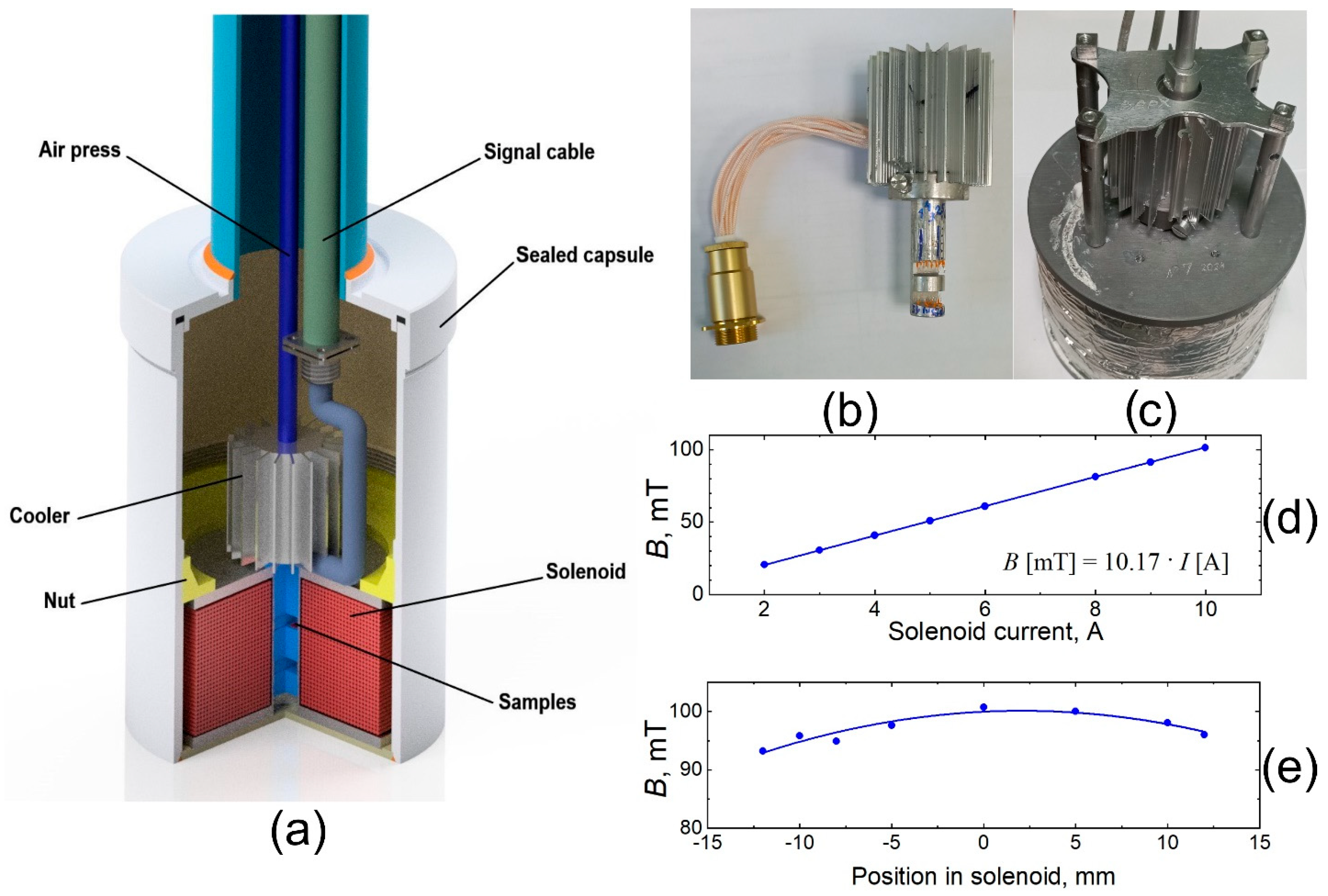
Figure 2 shows the structural diagram of the irradiation capsule positioned near the reactor core. The capsule has a cylindrical shape and houses a solenoid secured by a clamping nut. The samples under study are mounted on a quick-release insert (sample holder) placed inside the solenoid (Figure 2b). The insert is designed to accommodate up to six samples within the region of magnetic field uniformity. Each sample is connected via four electrical wires for current supply and voltage measurement. Electrical insulation between the samples and the insert body is achieved by attaching the samples to an insulating substrate using a thermally conductive, silica-based paste. The aluminum insert is additionally coated with a thick layer of insulating alumina through an anodic oxidation process. A calibrated temperature sensor, based on a platinum resistance thermometer, is also mounted into the sample holder. The signal wires are insulated with high-temperature polyimide and additionally glued with an aluminum oxide compound to prevent short-circuiting in the event of insulation degradation under high-fluence conditions. Prior to irradiation, the interwire insulation resistance of the signal cables exceeded 20 MΩ. At the end of the experiment, after two irradiation cycles, the insulation resistance decreased to approximately 5 MΩ, as estimated from the leakage currents and the power supply voltage.
A single large solenoid is used as a magnetic field source for all samples. This design is much more convenient than the configuration employing individual microsolenoids for each sample, as described in [19], where differences in solenoid geometry and sample positioning could lead to variations in magnetic field strength and orientation (planar Hall effect). The solenoid design was based on numerical calculations of the magnetic field, taking into account the wire diameter, solenoid geometry, and the dimensions of the reactor channel in the WWR-K facility. The solenoid was made of aluminum wire with radiation-resistant fiberglass insulation. Although aluminum has a higher electrical resistivity than copper, resulting in increased heat generation, copper’s large thermal-neutron-capture cross section leads to significant activation and the production of long-lived radioactive isotopes. In contrast, aluminum produces short-lived activation products, which reduces residual radioactivity, simplifies handling after irradiation, and allows the wires to be reused in subsequent experiments. At a supply current of 10 A, the solenoid produced a magnetic field of up to 0.11 T, as measured by a calibrated magnetometer (Figure 2d). The region of magnetic field uniformity extended over 20 mm along the solenoid axis, with field variation within this region not exceeding 3% (Figure 2e).
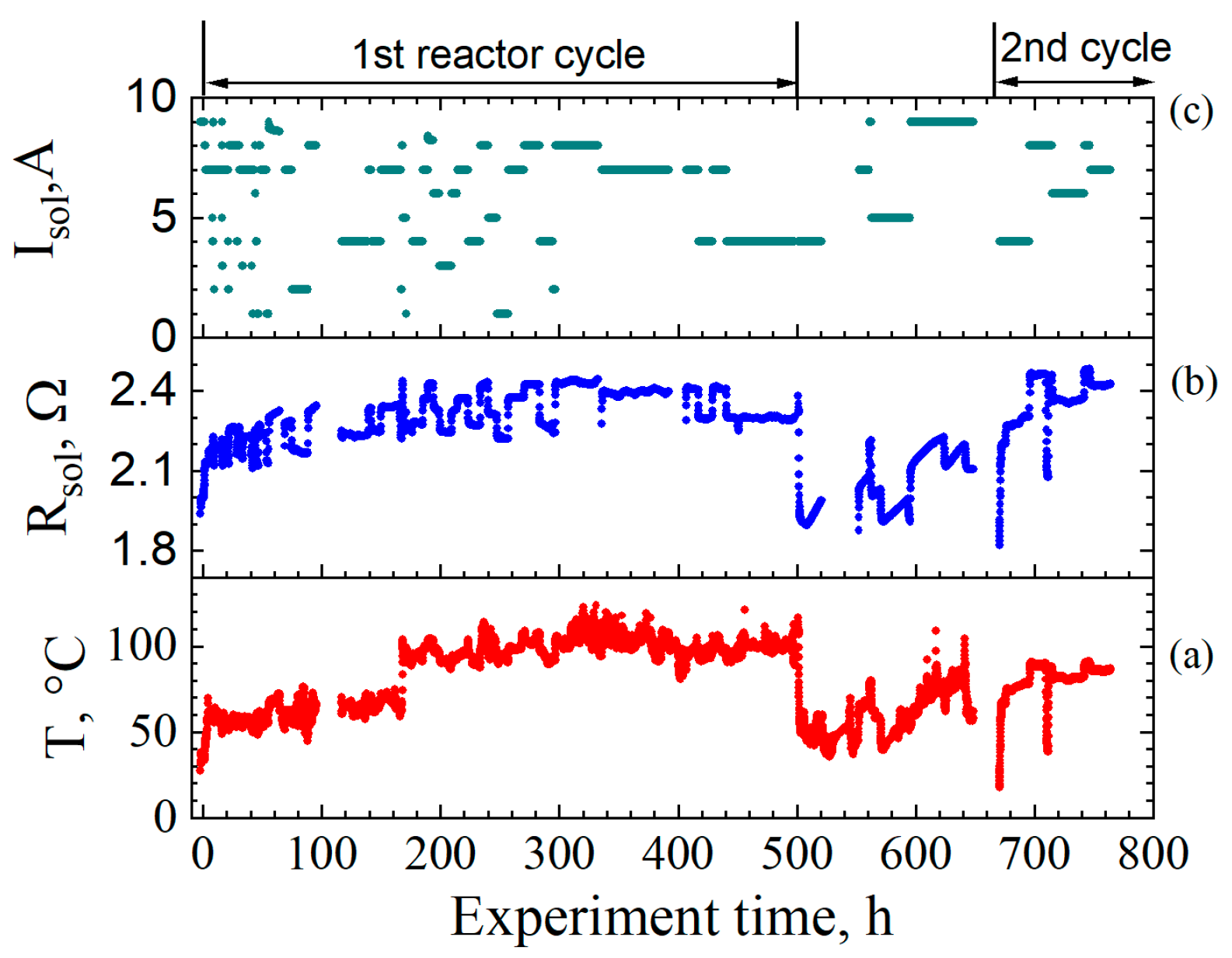
The temperature of the samples has a significant impact on the measured electrical characteristics, such as electron concentration and mobility, and can also alter the material properties through radiation-defect annealing. Therefore, particular attention was devoted to the monitoring and stabilization of sample temperature in the measuring system. Sample temperature is measured using calibrated platinum thermistor (Figure 3a). Thermal contact between the solenoid and the capsule body was optimized for heat dissipation to the water coolant. To reduce the heating effects caused by both neutron irradiation and Joule heating of the solenoid, an active cooling system for the insert with samples was implemented. The forced air-cooling system consists of an air supply tube (Figure 2a) connected to a piston compressor. To enhance heat dissipation from the samples, an aluminum cooling radiator was mounted onto the insert. The compressed air pressure was regulated in the range of 4 to 8 bar. The airflow was confined within the cooling radiator and did not directly impinge on the samples or their electrical contacts. All major components, including the solenoid, sample insert, and radiator, were rigidly mounted. Consequently, the airflow did not cause vibrations or introduce additional noise into the measurement signals. Excess pressure was vented from the irradiation zone to the air purification system through a long tube at the top.
The sample temperature was largely determined by the reactor environment, including the coolant water temperature, which exhibited daily fluctuations, and the reactor activity. The sample temperature was maintained within approximately 60 ± 10 °C during the first 180 h of the experiment and increased to roughly 100 ± 10 °C in the later stages.
During the experiment, the current and voltage across the solenoid were continuously recorded, enabling real-time calculation of its electrical resistance, as shown in Figure 3. This allowed estimation of the thermal power dissipated by the solenoid. As evident from Figure 3, the solenoid resistance correlates with both the temperature inside the capsule and the variation in current. The results confirm the high radiation resistance of the solenoid winding insulation, as no inter-turn short circuits were observed. Consequently, the magnetic field generated by the solenoid remained stable throughout the neutron irradiation process.
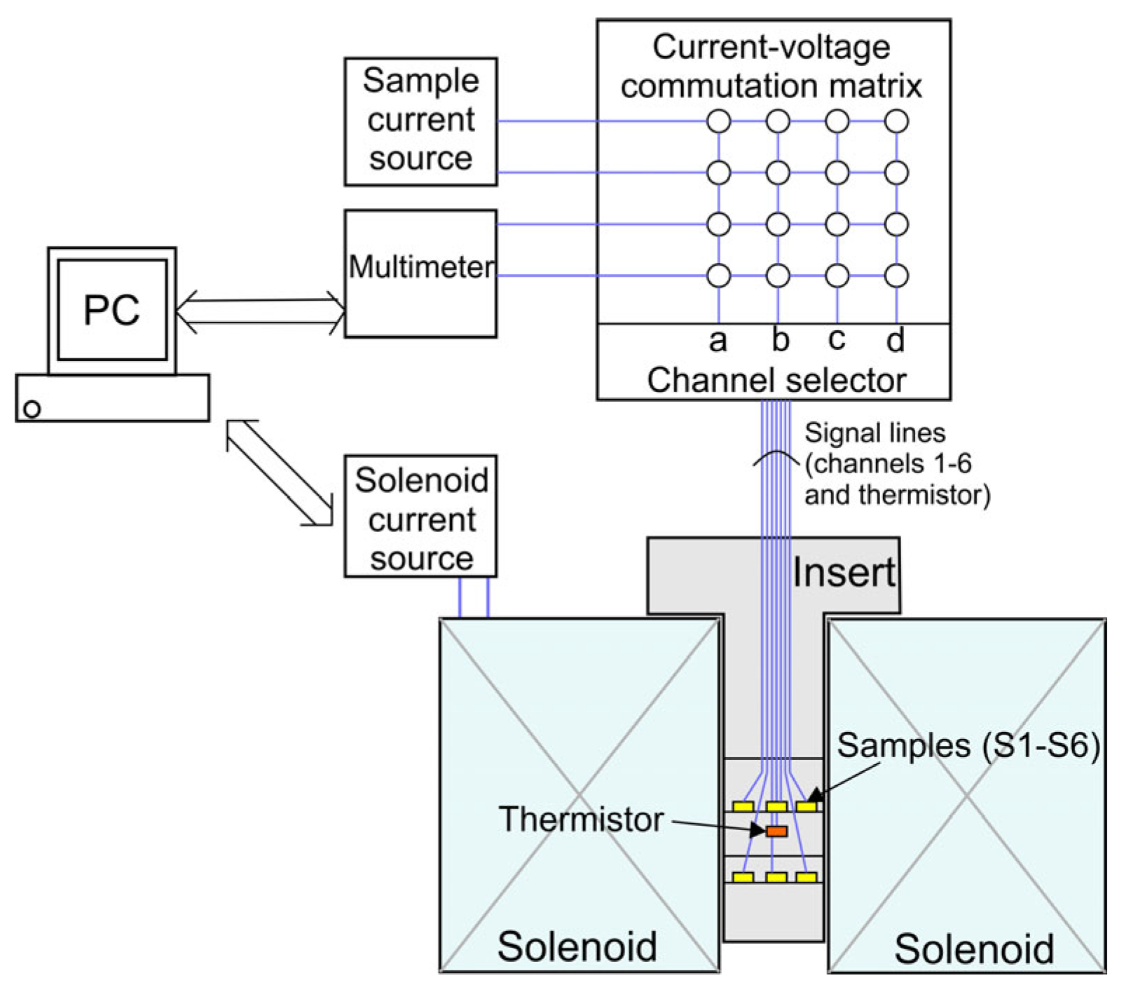
The schematic of the measuring system is shown in Figure 4. It included a digital multimeter, a stabilized current source for supplying samples with a current of 0.1 ÷ 5 mA, a solenoid power supply (with current range ISol = 0–10 A), and a switching device (commutator). The system was controlled via a personal computer, which also recorded the measurement data.
The electrical parameters of the samples—resistance, charge carrier concentration, and mobility—were determined by continuous measurements of conductivity and the Hall effect using a four-terminal configuration, which eliminates the influence of contact resistance [40]. The samples had a square shape, fabricated by photolithography and chemical etching, with four ohmic contacts symmetrically positioned at the corners in the Van der Pauw geometry. Each sample was connected via four signal wires to a dedicated commutator.
The primary measurement procedure involved applying current to one pair of contacts on a sample and measuring the resulting voltage or current across the corresponding contact pairs using a digital multimeter. The commutator (Figure 4), specially developed for this experiment, comprises six channels, each with four electrical connectors. It consists of a channel selector and the voltage/current commutation matrix with 16 reed relays. The channel selector chooses the sample and connects its four leads (a, b, c, d) to the inputs of the commutation matrix. By opening and closing specific relays, the matrix routes the current source and multimeter connections to different sample contacts, forming various measurement configurations. These configurations enable measurement of both longitudinal and transverse voltages and currents for all possible combinations of current and voltage contacts. The process of reversing the current direction and measuring voltages for all contact permutations effectively eliminates parasitic thermal voltages and averages out sample non-idealities such as anisotropy, inhomogeneities, and variations in contact resistance. The parameters of all samples are measured sequentially within a short time frame.
Magnetic field control in the sample region is achieved by supplying current to the solenoid from a regulated power source. Measurement timing cycles are set by control software running on the computer, which also records the data. The duration of a full measurement cycle for a single sample ranges from 10 to 60 s, depending on stabilization delays and the number of repetitions performed to reduce noise. By periodically measuring these parameters across all samples—along with monitoring solenoid current, sample currents, and sample temperature—the system provides accurate, real-time tracking of the electrical characteristic changes (charge density, mobility, resistivity) of semiconductor materials and Hall sensor sensitivity under continuous neutron irradiation.

2.2. Uncertainty and Validity Window

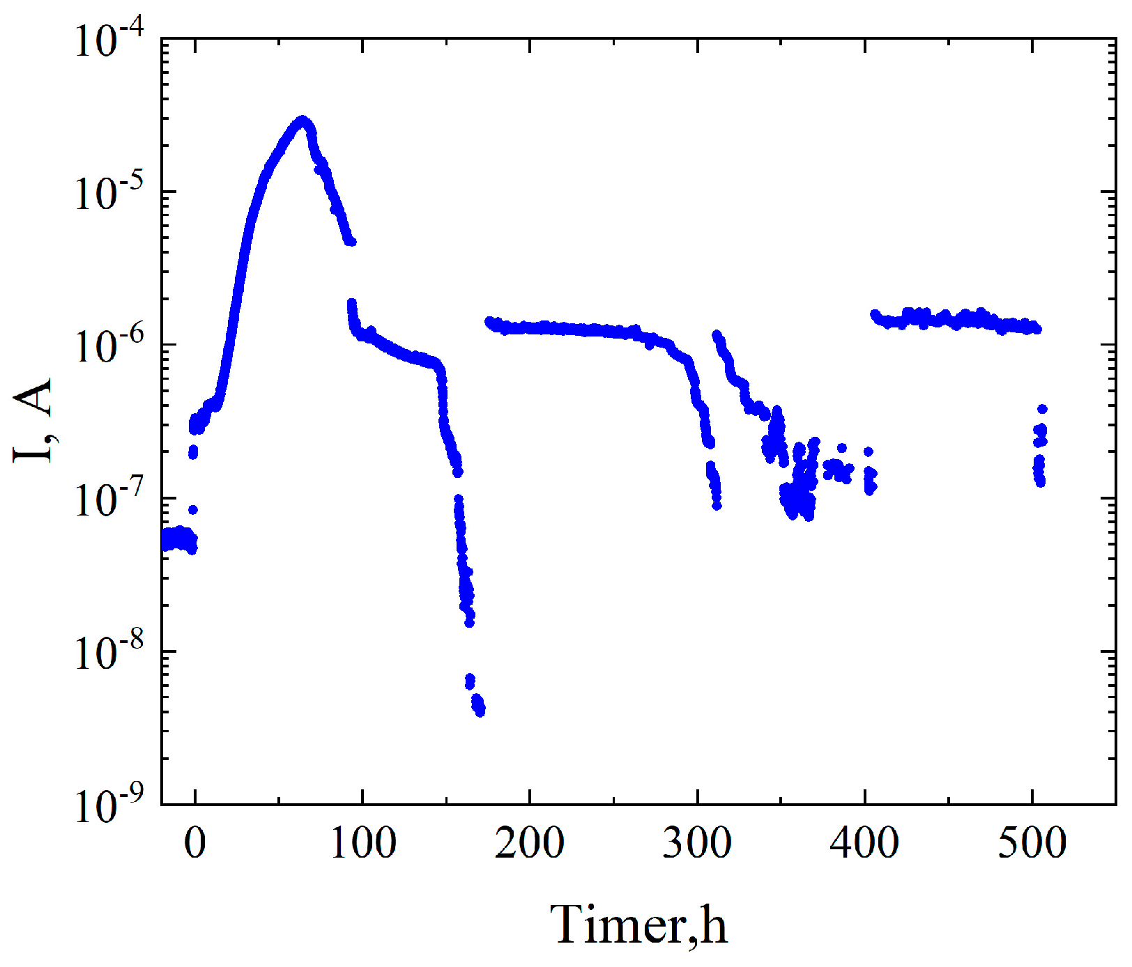
The novelty of the work is the measurement of the insulation resistance of signal conductors to assess its radiation-induced degradation. An earth conductor connected to the sample holder and three contacts from different samples in the capsule were connected to the four contacts of the sixth channel of the commutator. By applying a current between pairs of these contacts and measuring the resulting leakage current, we were able to estimate the insulation resistance both between channels and from channels to ground. Figure 5 presents the leakage current dependence measured between the test sample S1 (described in the next section) and ground. It follows from Figure 5 that before irradiation the leakage current was approximately 50 nA. An increase in leakage current was detected almost simultaneously with the core activity at the power levels of 0.5 ÷ 1 MW. Within about 2 h after the reactor startup, all measured leakage currents rose to values between 100 and 300 nA and stabilized at that level. Approximately 15 h after startup, a monotonic increase in leakage currents was observed. This increase in interchannel leakage can significantly impair the accuracy of sample characterization by introducing parallel parasitic conduction paths, which become more problematic as sample resistance rises under irradiation. Notably, four days after reactor startup, leakage currents decreased, on average, to the microampere range, as shown in Figure 5.
Leakage currents can influence the measured voltage and current values by intermittently shunting the wiring. The insulation resistance can be estimated by dividing the maximum (open-circuit) voltage of the current source by the leakage current. For typical leakage currents of 10−6 A, this corresponds to approximately 20 MΩ; during peak leakage events, the insulation resistance dropped to around 500 kΩ. The accuracy of the measurements depends on the ratio between the sample resistance and the insulation resistance of the measurement channel. Assuming a 5% uncertainty in material property measurements, sample resistances up to ~1 MΩ can be reliably measured under normal conditions, decreasing to approximately 25 kΩ during periods of higher leakage.
The raw data obtained from in situ measurements are rarely presented in publications, nor is there much discussion of issues related to leakage and instrumentation errors. Some features similar to those we observed were reported in the early work of Duran et al. [10], where fluences up to 1018 cm−2 were achieved. At long irradiation times, data scatter and stochastic outliers in the measurements increase. The authors observed stochastic spikes in the voltage signals of some samples after 450 h of irradiation, which were associated with deterioration of the output cable insulation and resulting intermittent short-circuit events. Nevertheless, the exact nature of the insulation leakage and short circuits has not been fully characterized or discussed, although these effects appeared to be reversible. Previous in-reactor studies of electronic properties, mainly carried out in collaboration with I. Bolshakova’s laboratory, employed a measurement technique that has been proven reliable for long-term operation under JET TOKAMAK conditions over five years, with an integrated neutron fluence of 3·1018 cm−2 [41]. The measurement accuracy reported for a Hall voltage of 0.l% had been achieved by an in situ equipment calibration procedure via a test current applied to copper microsolenoid [19]. The achievable accuracy relies on the assumption that the solenoid coils remain stable without electrical shorts or mechanical displacements, which may not hold under harsh conditions. At much higher fluences, enameled wire with varnish insulation should be avoided due to the degradation of the polymer insulation.
Magnetic field induction is a crucial factor in studying electron properties, and increasing the field strength enhances the measurement signal. This is particularly important for metallic-like thin films, where the Hall voltage is relatively low. Unfortunately, in previous studies the applied magnetic field was relatively low compared to the typical values in TOKAMAK facilities, reaching only about 2.5 mT [10], 7 mT [42], or 5 mT [43]. This limitation made it necessary to average the measured voltage values over more than 1000 points, which extended the acquisition time for the actual parameters to several minutes.
Our setup offers several advantages, including a stronger magnetic field and a larger, more homogeneous solenoid. The achieved values of fluence and measurement accuracy are typical and comparable to those reported in other studies. However, a significant improvement was achieved in measurement speed: 5–10 s per point compared to about 2 min reported by Bolshakova for metallic sensors. Furthermore, no data on leakage currents in electrical measurements of semiconductors under similar conditions were found in the literature.

3. Results and Discussion

The samples under study were grown by molecular beam epitaxy using a Riber Compact 21-T system at MEPhI. Two samples with different substrate materials and structural designs were investigated. Sample 1 (S1) contains a strained AlGaAs/InxGa1−xAs/GaAs quantum well structure grown on a semi-insulating GaAs (100) substrate [44]. The thickness of the InxGa1−xAs quantum well is 10 nm, with an indium content of x = 0.25. A silicon δ-doping layer is positioned within the AlGaAs barrier layer, resulting in the formation of a high-mobility two-dimensional electron gas within the InGaAs layer. Before irradiation, the sheet electron concentration nS in S1 was 1.6·1012 cm−2 and the electron mobility μ = 6200 cm2/V·s. Sample 2 (S2) was grown on a semi-insulating iron-doped InP substrate. It contained a 400 nm thick In0.52Al0.48As buffer layer, a 16 nm In0.53Ga0.47As quantum well, and an In0.52Al0.48As barrier layer containing silicon δ-doping. The quantum well contains a two-dimensional electron gas with an electron concentration of 3.6·1012 cm−2 and a mobility of 4500 cm2/V·s. The effect of neutron irradiation on quantum well heterostructures has been investigated in a number of post-irradiation studies, mostly focusing on the device characteristics of the transistors [34,36,37]. However, fundamental processes concerning the changes in electron concentration and mobility in heterostructures with quantum wells have not been systematically investigated.
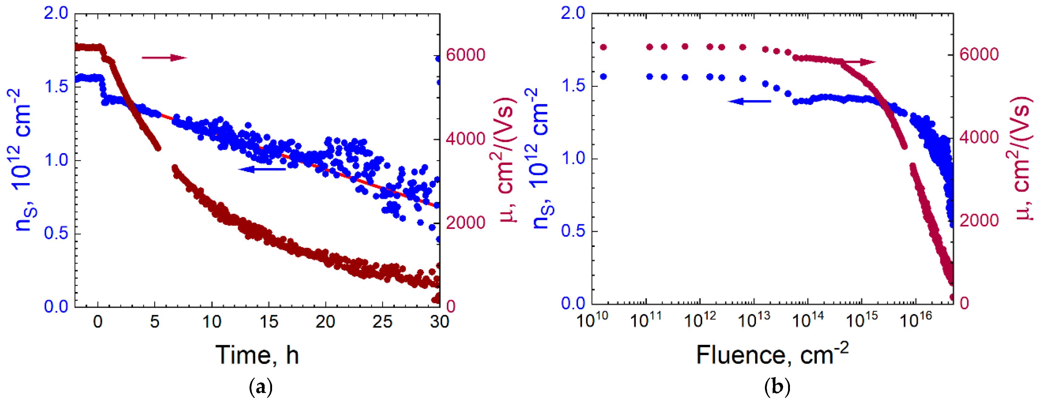
The electronic properties of investigated structures were measured as a function of time during neutron irradiation. The elapsed time from the reactor start was converted into neutron fluence to analyze the temporal evolution of the sheet electron concentration ns, electron mobility μ, and sheet resistance ρ. For the known reactor power, the time scale was recalculated to the neutron dose. Figure 6a shows the evolution of electron properties in sample 1 (S1) over the time. Before reactor startup, both the electron concentration and mobility remained stable and consistent with laboratory measurements. Immediately after reactor activation, a rapid drop in these parameters is observed. At this stage, there was a rapid increase in reactor power, as well as a rise in the sample temperature by 30 °C. We believe that the observed changes are a result of radiation-induced damage to the samples rather than a thermal effect, since laboratory tests on control samples showed a slight increase in electron concentration with temperature. Following this initial phase, a gradual increase in sheet resistance is recorded, accompanied by a steady decline in both electron concentration and mobility, indicating neutron-mediated modification of the sample’s electronic properties under reactor irradiation exposure. Approximately 30 h after reactor startup, the noise level in the measured data significantly increases. We attribute this effect to the rising leakage currents through the wiring insulation. This elevated noise disturbed the reliable determination of the electronic properties of the S1 beyond 30 h of irradiation and corresponding neutron fluence of 5·1016 cm−2.
Figure 6b shows that the electron concentration and mobility in the quantum well AlGaAs/InGaAs/GaAs sample exhibit different behavior upon the neutron irradiation. The electron mobility begins to degrade at a neutron fluence of approximately 4·1014 cm−2, while the electron concentration remains nearly constant up to a fluence of about 2·1015 cm−2. As shown in Figure 6a, the sheet electron concentration then decreases approximately linearly with the increasing fluence. The slope of this linear dependence is 1.57·10−5, which characterizes the electron removal rate in the quantum well per unit fluence. Based on this trend, an additional quantitative assessment of the radiation tolerance of sample S1 can be obtained by trend line intersection with the zero-electron concentration. This extrapolation yields a critical fluence value of approximately 9·1016 cm−2, beyond which the quantum well becomes depleted of free carriers. This estimate does not take into account possible nonlinear effects arising at higher fluences. In contrast, the electron mobility exhibits a nonlinear dependence on neutron fluence, approximately following an inverse logarithmic trend, as seen in Figure 6b. The distinct behavior of carrier concentration and mobility under irradiation are attributed to different underlying degradation mechanisms. While the concentration decline is associated with carrier trapping and defect-related depletion, the reduction in mobility is primarily due to enhanced carrier scattering by radiation-induced defects.
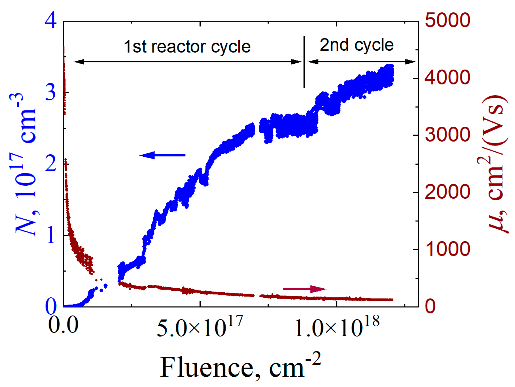
For sample 2, the measured resistance decreased during the neutron irradiation. In contrast to S1, the decrease in resistance of S2 allowed for stable long-term measurement of its electrophysical characteristics throughout the irradiation time during two cycles of reactor operation (approximately 900 h). Over this period, a monotonic increase in the apparent sheet electron concentration was observed—from an initial value of 3.6·1012 cm−2 to approximately 1·1016 cm−2. The nano-sized quantum well formed by the InAlAs/InGaAs/InAlAs heterostructure cannot physically accommodate such a high carrier density due to the Pauli exclusion principle. The samples S1 and S2 significantly differ by the thick (0.35 mm) monocrystalline substrate material—GaAs for S1 and InP for S2. Therefore, the observed difference in electron concentration dependence is attributed to neutron-induced transmutation doping in the InP substrate [45]. As a result of transmutation doping, the initially insulating InP substrate became conductive, giving rise to a parallel conduction channel through the substrate, while the conductivity of the InGaAs quantum well itself was progressively degraded during neutron irradiation.
Figure 7 shows the temporal evolution of the volume (bulk) electron concentration N, calculated as the sheet concentration divided by the InP substrate thickness of 350 μm. Figure 7 shows that the electron concentration in the InP substrate increases monotonically throughout the experiment, reaching 3·1017 cm−3 at a neutron fluence of 1.2·1018 cm−2. The growth in electron concentration is nearly linear with respect to fluence, although a slightly sublinear trend becomes noticeable at higher fluence levels. The monotonic and significant fall in electron mobility was also observed in sample 2.
The transmutation doping involves the capture of thermal neutrons by the natural isotopes present in the irradiated sample, followed by nuclear decay processes that generate electrically active dopants. In the studied system, the isotope of 115In possesses the largest thermal-neutron-capture cross section. After capturing a neutron, it undergoes nuclear decay into 116Sn, with a half-life of approximately 54 min. We can estimate the expected concentration of the resulting tin atoms by using the known thermal-neutron-capture cross section (σ = 199 b [46]), the thermal neutron fluence F, and the concentration NIn = 2·1022 cm−3 of indium in the InP substrate, according to the relation NSn = NIn·σ·F [45,47]. At a total neutron fluence of 1.2·1018 cm−2, the corresponding thermal neutron fluence is F = 6.2·1017 cm−2. Using this value, the estimated tin atom concentration is 2.5·1018 cm−3. The electron concentration data in Figure 7 are approximately one order of magnitude lower than both the present estimation and the results of previous studies on the neutron transmutation doping of InP [45,47,48,49] for comparable thermal neutron fluences. However, it should be noted that, in addition to donor impurities, irradiation also generates defects that act as compensating centers and reduce the free carrier concentration. Therefore, full activation of tin impurities typically requires post-irradiation annealing, whereas our experiment represents in situ measurements without annealing.
Thus, in this work, a methodology for real-time measurement of semiconductor material parameters under neutron irradiation is described. The developed methodology is not limited to III–V semiconductors and can be readily adapted for a broad range of materials under investigation for radiation-hard applications. To be compatible with the measurement system, the materials should possess sufficient electrical conductivity (sheet resistance below 100 kΩ/□) and be equipped with four ohmic contacts to ensure reliable four-terminal measurements of conductivity and the Hall effect. This allows the determination of resistivity, carrier type, concentration, and mobility in real time during irradiation. In particular, wide-bandgap semiconductors (e.g., SiC, GaN), conducting oxides, and low-dimensional systems, such as graphene and related 2D materials, can be studied using the same in situ approach. Such investigations would enable systematic comparison of degradation and transmutation effects across different material classes and provide critical insights for the design of next-generation electronic and sensor devices for fusion and other extreme environments.

4. Conclusions

In this work, a novel experimental methodology was developed and implemented for in situ measurements of the neutron modification of semiconductor materials’ electron transport properties under high neutron flux conditions in a research nuclear reactor. The measurement system enables real time monitoring of key electronic parameters such as resistivity, carrier concentration and mobility during irradiation, eliminating the limitations of post-irradiation analysis caused by induced radioactivity.
The system demonstrates high reliability under long-term neutron exposure up to a total fluence of 1.2·1018 cm−2, including stable operation of the radiation-hard solenoid for the magnetic field and acceptable electrical wiring insulation. Further work will focus on upgrading the insulation system and reducing interchannel leakage, with the aim of extending the effective measurement time for analyzing the electrical parameters of materials under neutron irradiation and enabling studies at higher integral neutron fluences.
The results obtained for the two types of InGaAs-based heterostructures revealed different radiation response mechanisms: in the GaAs-based structure the progressive degradation of mobility and carrier concentration was observed, while the InP-based structure exhibited a substantial increase in carrier concentration attributed to neutron-induced transmutation doping of the thick InP substrate.
These findings emphasize the importance of in situ diagnostics for an accurate assessment of radiation effects, not only in terms of degradation but also the neutron-induced doping of materials, and confirm the potential of the developed technique for systematic studies of the radiation resistance of conventional and advanced semiconductor materials. The methodology is particularly relevant for the design and qualification of magnetic field sensors and other electronic components for use in extreme environments, such as those found in thermonuclear fusion reactors.

Author Contributions

Conceptualization, I.S.V. and M.V.B.; methodology, I.S.V., P.V.N. and A.Y.; software, P.V.N.; validation, E.M., A.N. and R.B.; formal analysis, A.B. and B.M.; investigation, A.N.K., I.S.V., A.Y., A.N.V. and A.B.; resources, A.V.G., A.B. and N.I.K.; data curation, E.M. and R.N.; writing—original draft preparation, A.N.K. and A.Y.; writing—review and editing, I.S.V., M.V.B. and A.B.; visualization, N.S., D.K. and R.N.; supervision, I.S.V. and A.B.; project administration, I.S.V., B.M. and N.I.K. All authors have read and agreed to the published version of the manuscript.

Funding

This research was funded by the Science Committee of the Ministry of Science and Higher Education of the Republic of Kazakhstan (Grant No. AP23490409) and by the Ministry of Science and Higher Education of the Russian Federation (Agreement No. 075-15-2021-1352).

Data Availability Statement

Data are contained within the article.

Conflicts of Interest

The authors declare no conflicts of interest.

References

  1. Prinzie, J.; Simanjuntak, F.M.; Leroux, P.; Prodromakis, T. Low-power electronic technologies for harsh radiation environments. Nat. Electron. 2021, 4, 243–253. [Google Scholar] [CrossRef]
  2. Ren, Y.; Zhu, M.; Xu, D.; Liu, M.; Dai, X.; Wang, S.; Li, L. Overview on Radiation Damage Effects and Protection Techniques in Microelectronic Devices. Sci. Technol. Nucl. Install. 2024, 2024, 3616902. [Google Scholar] [CrossRef]
  3. Muhammad, Z.; Wang, Y.; Zhang, Y.; Vallobra, P.; Peng, S.; Yu, S.; Lv, Z.; Cheng, H.; Zhao, W. Radiation-Tolerant Electronic Devices Using Wide Bandgap Semiconductors. Adv. Mater. Technol. 2023, 8, 2200539. [Google Scholar] [CrossRef]
  4. Vayakis, G.; Walker, C. ITER International Team and Participant Teams Magnetic Diagnostics for ITER/BPX Plasmas (Invited). Rev. Sci. Instrum. 2003, 74, 2409–2417. [Google Scholar] [CrossRef]
  5. Quercia, A.; Pironti, A.; Bolshakova, I.; Holyaka, R.; Duran, I.; Murari, A.; Contributors, J. Long Term Operation of the Radiation-Hard Hall Probes System and the Path toward a High Performance Hybrid Magnetic Field Sensor. Nucl. Fusion 2022, 62, 106032. [Google Scholar] [CrossRef]
  6. Entler, S.; Duran, I.; Kocan, M.; Vayakis, G.; Kohout, M.; Sebek, J.; Sladek, P.; Grover, O.; Vyborny, K. Prospects for the Steady-State Magnetic Diagnostic Based on Antimony Hall Sensors for Future Fusion Power Reactors. Fusion Eng. Des. 2019, 146, 526–530. [Google Scholar] [CrossRef]
  7. Khadka, D.B.; Kuo, Y.-C.; Li, Y.Z.; Waqas, M.; Xu, Y.-J.; Yanagida, M.; Nishihara, H.; Tsukagoshi, K.; Chou, M.M.C.; Shirai, Y.; et al. Coordination Nanosheets Stabilizing Efficient Tin-Based Perovskite Solar Cells, ACS Appl. Mater. Interfaces 2025, 17, 26813–26822. [Google Scholar] [CrossRef]
  8. Antuzevics, A.; Elsts, E.; Kemere, M.; Lushchik, A.; Moskina, A.; Scherer, T.A.; Popov, A.I. Thermal annealing of neutron irradiation generated paramagnetic defects in transparent Al2O3 ceramics. Opt. Mater. 2023, 135, 113250. [Google Scholar] [CrossRef]
  9. León, M.; Martín, P.; Vila, R.; Molla, J.; Ibarra, A. Neutron irradiation effects on optical absorption of KU1 and KS-4V quartz glasses and Infrasil 301. Fusion Eng. Des. 2009, 84, 1174–1178. [Google Scholar] [CrossRef]
  10. Duran, I.; Hron, M.; Stockel, J.; Viererbl, L.; Vsolak, R.; Cerva, V.; Bolshakova, I.; Holyaka, R.; Vayakis, G. Stability of the Hall Sensors Performance under Neutron Irradiation. In Proceedings of the 12 International Congress on Plasma Physics—ICPP, Nice, France, 25–29 October 2004. [Google Scholar]
  11. Kiseleva, E.V. Stability of Quasi-Ballistic MESFETs with Various Buffer Layer Structures under Irradiation with Neutrons Possessing Different Energy Spectra. Tech. Phys. Lett. 2005, 31, 881–884. [Google Scholar] [CrossRef]
  12. Brudnyi, V.N.; Boiko, V.M.; Kolin, N.G.; Kosobutsky, A.V.; Korulin, A.V.; Brudnyi, P.A.; Ermakov, V.S. Neutron Irradiation-Induced Modification of Electrical and Structural Properties of GaN Epifilms Grown on Al2O3 (0001) Substrate. Semicond. Sci. Technol. 2018, 33, 095011. [Google Scholar] [CrossRef]
  13. Boiko, V.M.; Brudnii, V.N.; Ermakov, V.S.; Kolin, N.G.; Korulin, A.V. On the Electronic Properties of GaSb Irradiated with Reactor Neutrons and Its Charge Neutrality Level. Semiconductors 2015, 49, 763–766. [Google Scholar] [CrossRef]
  14. Vesaghi, M.A. Electrical Properties of Neutron-Transmutation-Doped GaAs below 450 K. Phys. Rev. B 1982, 25, 5436–5450. [Google Scholar] [CrossRef]
  15. Kuriyama, K.; Yokoyama, K.; Satoh, A. Thermally Stimulated Current in Neutron-Transmutation-Doped Semi-Insulating GaAs. Appl. Phys. Lett. 1991, 59, 1326–1328. [Google Scholar] [CrossRef]
  16. Brudnyi, V.N.; Krivov, M.A. Radiation Defects in Gallium Arsenide. Sov. Phys. J. 1980, 23, 45–54. [Google Scholar] [CrossRef]
  17. Goltzené, A.; Schwab, C.; David, J.P.; Roizes, A. Electrical Behavior of Fast Neutron Irradiated Semi-Insulating GaAs during Thermal Recovery. Appl. Phys. Lett. 1986, 49, 862–864. [Google Scholar] [CrossRef]
  18. Bolshakova, I.A.; Boiko, V.M.; Brudnyi, V.N.; Kamenskaya, I.V.; Kolin, N.G.; Makido, E.Y.; Moskovets, T.A.; Merkurisov, D.I. The Effect of Neutron Irradiation on the Properties of N-InSb Whisker Microcrystals. Semiconductors 2005, 39, 780–785. [Google Scholar] [CrossRef]
  19. Bolshakova, I.; Belyaev, S.; Bulavin, M.; Brudnyi, V.; Chekanov, V.; Coccorese, V.; Duran, I.; Gerasimov, S.; Holyaka, R.; Kargin, N.; et al. Experimental Evaluation of Stable Long Term Operation of Semiconductor Magnetic Sensors at ITER Relevant Environment. Nucl. Fusion 2015, 55, 083006. [Google Scholar] [CrossRef]
  20. Jankowski, J.; Prokopowicz, R.; Pytel, K.; El-Ahmar, S. Toward the Development of an InSb-Based Neutron-Resistant Hall Sensor. IEEE Trans. Nucl. Sci. 2019, 66, 926–931. [Google Scholar] [CrossRef]
  21. Gerstenberg, H.; Muller, P. Shubnikov-de Haas Effect Study of InAs after Transmutation Doping at Low Temperatures. J. Phys. Condens. Matter 1990, 2, 6945–6951. [Google Scholar] [CrossRef]
  22. Entler, S.; Soban, Z.; Duran, I.; Kovarik, K.; Vyborny, K.; Sebek, J.; Tazlaru, S.; Strelecek, J.; Sladek, P. Ceramic-Chromium Hall Sensors for Environments with High Temperatures and Neutron Radiation. Sensors 2021, 21, 721. [Google Scholar] [CrossRef]
  23. Kocan, M.; Duran, I.; Entler, S.; Vayakis, G.; Agostinetti, P.; Brombin, M.; Carmona, J.M.; Gambetta, G.; Jirman, T.; Marconato, N.; et al. Steady State Magnetic Sensors for ITER and beyond: Development and Final Design (Invited). Rev. Sci. Instrum. 2018, 89, 10J119. [Google Scholar] [CrossRef] [PubMed]
  24. Duran, I.; Entler, S.; Kočan, M.; Kohout, M.; Viererbl, L.; Mušálek, R.; Chráska, T.; Vayakis, G. Development of Bismuth Hall Sensors for ITER Steady State Magnetic Diagnostics. Fusion Eng. Des. 2017, 123, 690–694. [Google Scholar] [CrossRef]
  25. Kolin, N.G.; Merkurisov, D.I.; Solov’ev, S.P. Electrical Properties of Nuclear-Doped Indium Antimonide. Semiconductors 1999, 33, 712–715. [Google Scholar] [CrossRef]
  26. El-Ahmar, S.; Przychodnia, M.; Jankowski, J.; Prokopowicz, R.; Ziemba, M.; Szary, M.J.; Reddig, W.; Jagiełło, J.; Dobrowolski, A.; Ciuk, T. The Comparison of InSb-Based Thin Films and Graphene on SiC for Magnetic Diagnostics under Extreme Conditions. Sensors 2022, 22, 5258. [Google Scholar] [CrossRef]
  27. Bolshakova, I.; Dyuzhkov, D.; Kost, Y.; Radishevskiy, M.; Shurigin, F.; Vasyliev, A.; Wang, Z.; Otto, M.; Neumaier, D.; Bulavin, M.; et al. Graphene and Prospects of Radiation-Hard Hall Sensors. In Proceedings of the 2017 IEEE 7th International Conference Nanomaterials: Application & Properties (NAP), Odessa, Ukraine, 10–15 September 2017; pp. 03CBN15-1–03CBN15-5. [Google Scholar]
  28. Klochkov, A.N.; Yskakov, A.; Vinichenko, A.N.; Safonov, D.A.; Kargin, N.I.; Bulavin, M.V.; Galushko, A.V.; Yamurzin, V.R.; Vasil’evskii, I.S. Effect of Neutron Irradiation on the Electronic and Optical Properties of AlGaAs/InGaAs-Based Quantum Well Structures. Materials 2023, 16, 6750. [Google Scholar] [CrossRef]
  29. Fauzi, A.; Rashid, M.; Zin, M.R.M.; Hasbullah, N.F. Neutron Radiation Effects on the Electrical Characteristics of InAs/GaAs Quantum Dot-in-a-Well Structures. IEEE Trans. Nucl. Sci. 2015, 62, 3324–3329. [Google Scholar] [CrossRef]
  30. Fortuna, S.A.; Hughes, E.T.; Chow, W.W.; Addamane, S.; Alford, C.; Vizkelethy, G.; Bowers, J.E.; Skogen, E.J. Radiation-Resilient InAs Quantum Dot Lasers. APL Photonics 2025, 10, 041301. [Google Scholar] [CrossRef]
  31. Volkova, N.S.; Gorshkov, A.P.; Trufanov, A.N.; Istomin, L.A.; Levichev, S. Influence of Neutron Irradiation on Optoelectronic Properties of Structures with the InAs/GaAs Quantum Dots. J. Phys. Conf. Ser. 2019, 1410, 012137. [Google Scholar] [CrossRef]
  32. Papaioannou, G.J.; Papastamatiou, M.; Arpatzanis, N.; Dimitrakis, P.; Papastergiou, C. Neutron Radiation Effects in HEMTs. In Proceedings of the RADECS 93. Second European Conference on Radiation and Its Effects on Components and Systems (Cat. No.93TH0616-3), St. Malo, France, 13–16 September 1993; pp. 207–212. [Google Scholar]
  33. Duran, I.; Oszwaldowski, M.; Kovarík, K.; Jankowski, J.; El-Ahmar, S.; Viererbl, L.; Lahodová, Z. Investigation of Impact of Neutron Irradiation on Properties of InSb-Based Hall Plates. J. Nucl. Mater. 2011, 417, 846–849. [Google Scholar] [CrossRef]
  34. Papastamatiou, M.; Arpatzanis, N.; Papaioannou, G.J.; Papastergiou, C.; Christou, A. Neutron Radiation Effects in High Electron Mobility Transistors [AlGaAs/GaAs]. IEEE Trans. Electron Devices 1997, 44, 364–372. [Google Scholar] [CrossRef]
  35. Baramidze, N.V.; Bonch-Bruevich, V.L.; Giorgadze, M.P.; Kurdiani, N.I. Electrical Properties of InSb Irradiated with Fast Neutrons. Phys. Status Solidi B 1982, 110, 33–37. [Google Scholar] [CrossRef]
  36. Paccagnella, A.; Del Papa, C.; Chitussi, P.; Fuochi, P.G.; Benetti, P. Radiation Induced Degradation of Electrical Characteristics of III-V Devices. In Proceedings of the Gallium Arsenide Applications Symposium (GAAS), Turin, Italy, 28–30 April 1994. [Google Scholar] [CrossRef]
  37. Ohyama, H.; Simoen, E.; Kuroda, S.; Claeys, C.; Takami, Y.; Hakata, T.; Kobayashi, K.; Nakabayashi, M.; Sunaga, H. Degradation and Recovery of AlGaAs/GaAs p-HEMT Irradiated by High-Energy Particle. Microelectron. Reliab. 2001, 41, 79–85. [Google Scholar] [CrossRef]
  38. Aitkulov, M.T.; Dyussambayev, D.S.; Romanova, N.K.; Gizatulin, S.H.; Shaimerdenov, A.A.; Bugybay, Z.T.; Kisselyov, K.S.; Beisebayev, A.O. Measurement of the spatial-energy distribution of neutrons in the irradiation channel of the critical facility. J. Phys. Conf. Ser. 2022, 2155, 012021. [Google Scholar] [CrossRef]
  39. Shaimerdenov, A.; Gizatulin, S.; Dyussambayev, D.; Askerbekov, S.; Kenzhina, I. The WWR-K Reactor Experimental Base for Studies of the Tritium Release from Materials Under Irradiation. Fusion Sci. Technol. 2020, 76, 304–313. [Google Scholar] [CrossRef]
  40. Lindemuth, J. Hall Effect Measurement Handbook: A Fundamental Tool for Semiconductor Material Characterization; Lake Shore Cryotronics: Westerville, OH, USA, 2020. [Google Scholar]
  41. Bolshakova, I.; Quercia, A.; Coccorese, V.; Murari, A.; Holyaka, R.; Duran, I.; Viererbl, L.; Konopleva, R.; Yerashok, V. Magnetic Measuring Instrumentation With Radiation-Resistant Hall Sensors for Fusion Reactors: Experience of Testing at JET. IEEE Trans. Nucl. Sci. 2012, 59, 1224–1231. [Google Scholar] [CrossRef]
  42. Bolshakova, I.A.; Kost, Y.Y.; Radishevskyi, M.I.; Shurygin, F.M.; Vasyliev, O.V.; Wang, Z.; Neumaier, D.; Otto, M.; Bulavin, M.V.; Kulikov, S.A. Resistance of Hall Sensors Based on Graphene to Neutron Radiation. In Nanomaterials in Biomedical Application and Biosensors (NAP-2019); Pogrebnjak, A., Pogorielov, M., Viter, R., Eds.; Springer: Singapore, 2020; pp. 199–209. [Google Scholar] [CrossRef]
  43. Bolshakova, I.; Holyaka, R.; Marusenkova, T.; Shurygin, F. Radiation-Resistant Hall Magnetic Field Sensors and Instrumentations; Primedia Elaunch LLC: Dallas, TX, USA, 2022; p. 148. [Google Scholar] [CrossRef]
  44. Safonov, D.A.; Klochkov, A.N.; Vinichenko, A.N.; Sibirmovsky, Y.D.; Kargin, N.I.; Vasil’evskii, I.S. Electron Effective Masses, Nonparabolicity and Scattering Times in One Side Delta-Doped PHEMT AlGaAs/InGaAs/GaAs Quantum Wells at High Electron Density Limit. Phys. E Low Dimens. Syst. Nanostructures 2021, 133, 114787. [Google Scholar] [CrossRef]
  45. Kolin, N.G.; Merkurisov, D.I.; Solov’ev, S.P. Electrical Properties of Transmutation-Doped Indium Phosphide. Semiconductors 2000, 34, 150–154. [Google Scholar] [CrossRef]
  46. Yoon, J.; Ro, T.; Lee, S.; Yamamoto, S.; Kobayashi, K. Measurement of neutron capture cross-section of indium in the energy region from 0.003 eV to 30 keV. Ann. Nucl. Energy 2002, 29, 1157–1169. [Google Scholar] [CrossRef]
  47. Boudart, B.; Marí, B.; Prévot, B.; Schwab, C. Efficiency of neutron transmutation doping of InP investigated by optical and electrical methods. Nucl. Instrum. Methods Phys. Res. Sect. B Beam Interact. Mater. At. 1992, 63, 101–105. [Google Scholar] [CrossRef]
  48. Mari, B.; Prevot, B.; Schwab, C. Effective n-type doping of InP by the neutron transmutation technique. Mater. Sci. Eng. B 1993, 20, 113–116. [Google Scholar] [CrossRef]
  49. Najda, S.P.; Holmes, S.; Stradling, R.A.; Kuchar, F. Donor identification in neutron-transmutation-doped GaAs and InP. Semicond. Sci. Technol. 1989, 4, 791–796. [Google Scholar] [CrossRef]
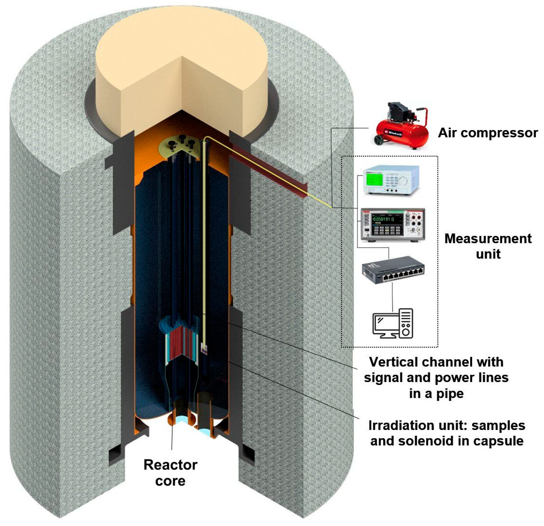
Figure 1. Schematic representation of the WWR-K reactor core and the location of the measuring system components.
Electronics 14 03802 g001
Figure 2. Capsule containing the solenoid and test samples: (a) structural diagram of the capsule; (b) sample holder (insert) with attached heat sink and connector for signal wires; (c) general view of the solenoid and the insert prior to installation in the capsule; (d) solenoid magnetic field versus current; (e) magnetic field uniformity measured along the solenoid axis.
Electronics 14 03802 g002
Figure 3. Time evolution of sample and solenoid parameters during neutron irradiation: (a) sample temperature; (b) solenoid resistance; (c) current through the solenoid.
Electronics 14 03802 g003
Figure 4. Measurement circuit diagram.
Electronics 14 03802 g004
Figure 5. Temporal evolution of the leakage currents from S1 to ground. The drops in current observed at 150 h and 300 h are due to battery depletion in the current source.
Electronics 14 03802 g005
Figure 6. Sheet electron concentration ns and electron mobility μ for the AlGaAs/InGaAs/GaAs quantum well sample (sample 1): (a) as a function of irradiation time (counted from the moment of the first reactor power increase), red line indicates linear fit; (b) as a function of integrated neutron fluence.
Electronics 14 03802 g006
Figure 7. Volume electron concentration N and electron mobility μ as a function of total neutron fluence for the InAlAs/InGaAs/InAlAs structure on InP substrate (sample 2).
Electronics 14 03802 g007
Table 1. Neutron energy distribution at the irradiated sample position.
NeutronsEnergyNeutron Flux Density,
cm−2s−1
Percentage of Total Flux,
%
Thermal0 ÷ 0.683 eV2.56·101152
Epithermal0.683 eV ÷ 1 MeV1.71·101134
Fast>1 MeV6.84·101014
Disclaimer/Publisher’s Note: The statements, opinions and data contained in all publications are solely those of the individual author(s) and contributor(s) and not of MDPI and/or the editor(s). MDPI and/or the editor(s) disclaim responsibility for any injury to people or property resulting from any ideas, methods, instructions or products referred to in the content.