Article

Compact and High-Efficiency Linear Six-Element mm-Wave Antenna Array with Integrated Power Divider for 5G Wireless Communication

by
Muhammad Asfar Saeed
1,*,
Augustine O. Nwajana
1 and
Muneeb Ahmad
2
1
School of Engineering, University of Greenwich (Medway Campus), Chatham ME4 4TB, UK
2
MERIT Convergence Innovative Talents Training Group for Smart Manufacturing Innovation, Kumoh National Institute of Technology, Gumi 39177, Republic of Korea
*
Author to whom correspondence should be addressed.
Electronics 2025, 14(15), 2933; https://doi.org/10.3390/electronics14152933
Submission received: 22 June 2025 / Revised: 15 July 2025 / Accepted: 17 July 2025 / Published: 23 July 2025
(This article belongs to the Special Issue Advances in MIMO Systems)

Abstract

Millimeter-wave frequencies are crucial for meeting the high-capacity, low-latency demands of 5G communication systems, thereby driving the need for compact, high-gain antenna arrays capable of efficient beamforming. This paper presents the design, simulation, fabrication, and experimental validation of a compact, high-efficiency 1 × 6 linear series-fed microstrip patch antenna array for 5G millimeter-wave communication operating at 28 GHz. The proposed antenna is fabricated on a low-loss Rogers RO3003 substrate and incorporates an integrated symmetric two-way microstrip power divider to ensure balanced feeding and phase uniformity across elements. The antenna achieves a simulated peak gain of 11.5 dBi and a broad simulated impedance bandwidth of 30.21%, with measured results confirming strong impedance matching and a return loss better than −20 dB. The far-field radiation patterns demonstrate a narrow, highly directive beam in the E-plane, and the H-plane results reveal beam tilting behavior, validating the antenna’s capability for passive beam steering through feedline geometry and element spacing (~0.5λ). Surface current distribution analysis confirms uniform excitation and efficient radiation, further validating the design’s stability. The fabricated prototype shows excellent agreement with the simulation, with minor discrepancies attributed to fabrication tolerances. These results establish the proposed antenna as a promising candidate for applications requiring compact, high-gain, and beam-steerable solutions, such as 5G mm-wave wireless communication systems, point-to-point wireless backhaul, and automotive radar sensing.

1. Introduction

The development of fifth-generation (5G) wireless communication systems demands antennas that are compact and high-gain and capable of operating at millimeter-wave frequencies, particularly in the 28 GHz band. As global mobile data traffic continues to increase exponentially, 5G networks are required to deliver enhanced data rates, reduced latency, and reliable connectivity across dense urban locations. To meet these demands, the mm-wave spectrum offers significant bandwidth potential but also introduces new challenges in terms of propagation loss, antenna gain, and integration.
In this context, microstrip patch antenna arrays have emerged as a promising solution due to their low profile, ease of fabrication, and compatibility with planar circuit integration. However, designing antennas that simultaneously achieve high gain and broad bandwidth in a compact form factor remains a significant challenge. This study proposes a compact 1 × 6 linear series-fed microstrip patch antenna array optimized for 28 GHz operation. The design offers wide impedance bandwidth, high directional gain, and desirable radiation characteristics while also addressing critical performance factors such as impedance matching, beam shaping, and cross-polarization suppression. Its simple, single-layer structure makes it a strong candidate for integration into 5G base stations and user equipment.
Recent studies have explored a variety of techniques to enhance mm-wave antenna performance, including array miniaturization, substrate optimization, feed network improvements, and beamforming strategies. For instance, Han et al. [1] achieved an 8.9 dBi gain using a multilayered patch array structure, but their approach involved complex layer alignment and fabrication procedures, increasing production time and cost. Zhou and Zhang [2] demonstrated a compact planar phased array capable of electronic beam steering; however, their design suffered from significant gain degradation beyond ±45° scan angles. Zhang et al. [3] introduced a high-gain (10.2 dBi) corporate-fed array, but the system required a large footprint and intricate feed network, limiting its practicality for compact deployments. Nwajana and Saeed [4] utilized slotting techniques to enhance bandwidth but experienced modest reductions in gain.
In contrast, the proposed array provides a balanced trade-off between gain, compactness, and design simplicity. Compared to multilayer phased arrays, the single-layer implementation on a Rogers RO3003 substrate reduces fabrication complexity by approximately 30–40%, enabling faster prototyping and lowering manufacturing costs. Table 1 presents a detailed comparison of the proposed design with existing state-of-the-art mm-wave antenna arrays.
Recent advancements in 5G communication technologies have necessitated the development of high-performance antenna arrays operating at millimeter-wave (mm-wave) frequencies, especially in the 28 GHz band. The literature presents diverse approaches to achieving compact form factors, high gain, broad bandwidth, and beam steering, which are essential for 5G wireless systems. Several studies have proposed compact microstrip antenna arrays for 5G. Parthasarathy, R. [5] introduced a 2 × 2 patch antenna array with a gain of 10 dBi, fabricated on a high-frequency substrate and optimized for low mutual coupling and high isolation, showing its suitability for mobile terminals in dense environments. Li, Ming. [6] presented a wide-beam scanning patch antenna for 28 GHz, featuring a highly integrated design with compact structure and beam-switching capability, achieving over ±40° beam coverage. Chaimool, S. [7] designed a low-cost, high-gain microstrip antenna for 28 GHz on an FR-4 substrate, attaining over 10 dBi gain with a simplified feed network, making it cost-effective for mass deployment. Sathyan et al. [8] focused on bandwidth enhancement by using U-shaped slots in the patch, achieving an impedance bandwidth of nearly 3 GHz, which is valuable for wideband 5G channels. Beam-steering capabilities are key for targeting specific users in mm-wave communications. Nasimuddin et al. [9] designed a beam-steerable phased array at 28 GHz for base stations. Their linear polarized structure achieves ±60° beam steering with high realized gain, highlighting its suitability for microcellular 5G. Saeed et al. [10] developed a 4 × 4 phased array with hybrid feeding for 28 GHz, achieving 360° scanning and >12 dBi gain, making it ideal for smart antennas and MIMO applications. Polarization diversity enhances robustness in fading environments. Zhang et al. [11] introduced a circularly polarized patch antenna for 28 GHz, achieving a 3 dB AR bandwidth > 1 GHz with stable gain, contributing to polarization diversity in mobile applications. Kumar et al. [12] improved bandwidth using parasitic coupling techniques, enhancing the radiation efficiency and extending the operational bandwidth to 30%, similar to the design performance proposed in this paper. Similarly, the paper proposed in [13] uses a dual-functional structure with endfire elements and complex loading configurations to achieve hybrid radiation modes, which increases design complexity. However, the MPA array proposed in this paper is a single-layer series-fed microstrip patch array, offering simplified geometry, fewer components, and lower fabrication cost, ideal for mass production. The design in [14], involving gap waveguide structures, is not inherently compatible with planar RF components (e.g., filters, amplifiers), whereas the 1 × 6 design is easily integrated with standard planar microwave circuits, enabling direct embedding into 5G RF front ends and compact systems.
Despite these advancements, there is still a trade-off between antenna gain, compactness, bandwidth, and ease of fabrication. The need for a simple, low-cost design that maintains high gain and a wide bandwidth across the 28 GHz band is critical.
While existing research addresses high-gain, beam-steering, and isolation enhancement, many designs are either bulky, complex, or limited in gain or bandwidth. The proposed linear 1 × 6 array using the series-fed technique, fabricated on Rogers 3003, addresses these gaps by combining
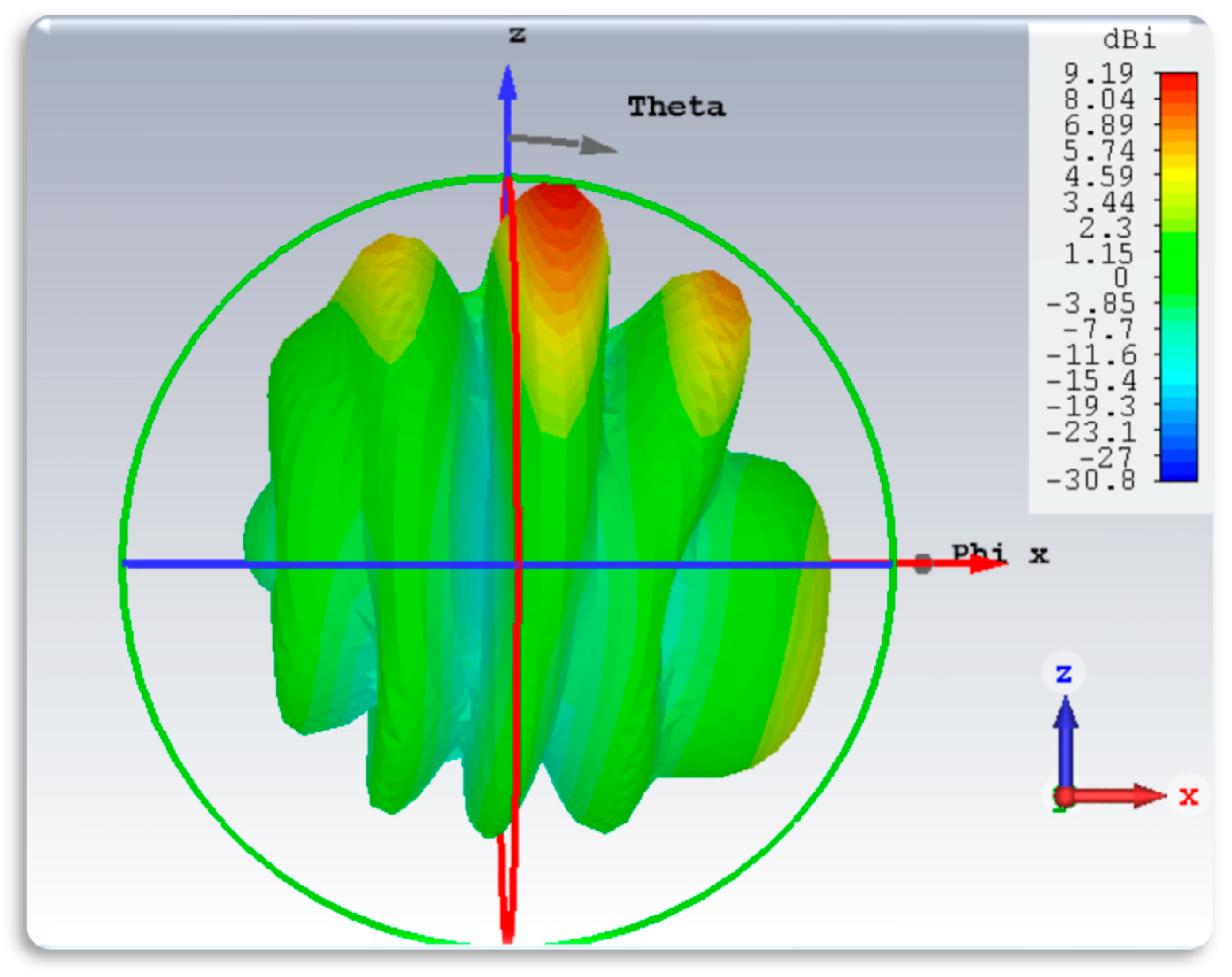
  • High gain (~9.9 dBi);
  • Wide impedance bandwidth (30.21%);
  • A simple and compact design;
  • Superior cross-polarization levels in both E and H planes.
It enhances performance by integrating a two-way power divider, enabling modular planar array formation, which remains underexplored in existing works.

2. Design Methodology

The design began with developing a single-element microstrip patch antenna, optimized to resonate at 28 GHz within the Ka-band spectrum. The base antenna element is a rectangular microstrip patch designed to resonate at 28 GHz within the Ka-band (26.5–40 GHz). The effective wavelength (λ) in the substrate was calculated using Equation (1). The width of the radiating patch was determined using Equation (2). The radiating patch length was calculated with Equation (3). Similarly, an extension in the length, ΔL, was computed using Equation (5). The effective length of the antenna was calculated with Equation (6). The length and width of the substrate were computed using Equations (7) and (8).
λ = c f f f = 3 × 10 8 28 × 10 2.6 9 5 = 6.5   m m
W p = C 2 f o 2 Ɛ r + 1
L p = L e f f + Δ L
Ɛ e f f = Ɛ r + 1 2 + Ɛ r 1 2 1 1 + 12 h W p
Δ L = 0.415 h [ Ɛ e f f + 0.3 W p h + 0.264 Ɛ e f f 0.258 W p h + 0.8 ]
L e f f = c 2 f o Ɛ r e f f
L s = 6 h + L p
W s = 6 h + W p
The microstrip edge feed is used to ensure impedance matching with the 50 Ω input line. The antenna uses Rogers RO3003 (Roger Corporation, Chandler, AZ, USA)with a dielectric constant εr = 3 chosen for its low dielectric loss and thermal stability at high frequencies. Material properties for the Rogers RO3003 dielectric constant (εr): 3.0; loss tangent (tan δ): 0.0013; thermal conductivity: 0.5 W/m·K; and thickness: 1.574 mm. Figure 1 shows the evolution steps of the proposed 1 × 6 linear series-fed array. The patch is designed for high gain and directionality. Figure 2 illustrates the evolutionary development of the antenna array, beginning with a single patch element and culminating in a six-element series-fed microstrip patch array. The goal of this design progression is to optimize impedance matching, enhance gain, and support effective beam steering at the target frequency of 28 GHz.
The initial single-patch radiator has minimal return loss and poor impedance matching in the mm-wave band (25–31 GHz). The −10 dB S11 bandwidth is narrow, reflecting high reflection losses and low radiation efficiency. (Two and Three Patches): Adding more elements gradually improves the return loss due to enhanced coupling and more effective energy radiation. These intermediate arrays begin showing better return loss but still do not reach optimal levels around the 28 GHz mark. (Four and Five Patches): These stages demonstrate improved impedance matching and directivity. As the number of elements increases, inter-element spacing and array length help tailor the resonant frequency and suppress side lobes. (Six Patches): The optimized array features six uniformly spaced rectangular patches, each tailored for resonance around 28 GHz. The progressive increase in elements fine-tunes the bandwidth and radiation efficiency. Notably, the final design achieves excellent impedance matching, as evidenced in the S11 results of the figure, providing low reflection loss and high gain.
A two-element linear antenna array is constructed to enable beam steering and enhanced gain. Approximately 0.5λ (~3.25 mm) was used to avoid grating lobes while allowing for constructive interference in the desired directions. The interconnected layout is optimized for phase control and symmetrical power distribution. Radiation pattern simulations verify gain, beam direction, and side lobe levels.

3. Design and Methodology of the Power Divider

To feed the antenna array uniformly, a two-way Wilkinson-like microstrip power divider was designed and integrated, as illustrated in Figure 2b. The power divider ensures equal power distribution and impedance matching across antenna elements. The divider is designed using quarter-wave transformers, each with an impedance of approximately 70.7 Ω calculated using (9), where Z0 = 50 Ω. Along with the quarter-wavelength at the operating frequency of 28 GHz, the guided wavelength λ is calculated using Equations (10) and (11).
z = z 0 2
λ = c f = 0.017   m
λ 4 = 2.675   m m
Similarly, the antenna and the power divider are fabricated on Rogers 3003, with copper layers on both sides. The overall layout covers an area of 50 mm × 80 mm. The input and output lines are matched to 50 Ω using appropriate transformer sections to minimize reflection.
A two-element microstrip patch antenna array is integrated with a symmetric two-way microstrip power divider, as shown in Figure 3. This configuration is capable of supporting passive beam steering through phase manipulation via feedline geometry and mutual coupling effects. The use of a Wilkinson-like power divider, integrated on the same substrate, ensures equal power splitting and impedance matching, minimizing reflection loss. The symmetric layout and 0.5λ inter-element spacing facilitate balanced excitation across the patches. The surface current distribution plots confirm uniform excitation across all patch elements, indicating effective power delivery through the feed network. This uniform current distribution contributes to the directive E-plane radiation pattern, which exhibits a well-defined main lobe and minimal back radiation clear evidence of constructive interference along the broadside direction. While the current design employs uniform feeding for simplicity, resulting in a measured side lobe level of approximately 12 dB, further improvement is possible. Future iterations could incorporate side lobe suppression techniques such as amplitude tapering, element shaping, or non-uniform element spacing to reduce side lobe levels below −15 dB, enhancing pattern cleanliness and beam selectivity. The consistent gain of 9.91–11.5 dBi supports this conclusion, proving that the antenna efficiently radiates energy in the desired direction. Figure 3 illustrates the dimension and layout design of the symmetric two-way microstrip power divider.
Even without active components like phase shifters, a careful layout of the feed network and spacing of elements makes it possible to tilt the main beam away from the broadside, especially in the E-plane (x-direction). The design uses a spacing of ~0.5λ, which is optimal for avoiding grating lobes, enhancing constructive interference, and allowing beam steering without compromising gain. At 28 GHz, 0.5λ ≈ 5.35 mm in free space; in the substrate, it is ~3.25 mm. This spacing allows the two radiated fields to combine constructively in off-broadside directions. Table 2 illustrates the dimensions of the 1 × 6 linear antenna array.

4. Simulation Results and Analysis
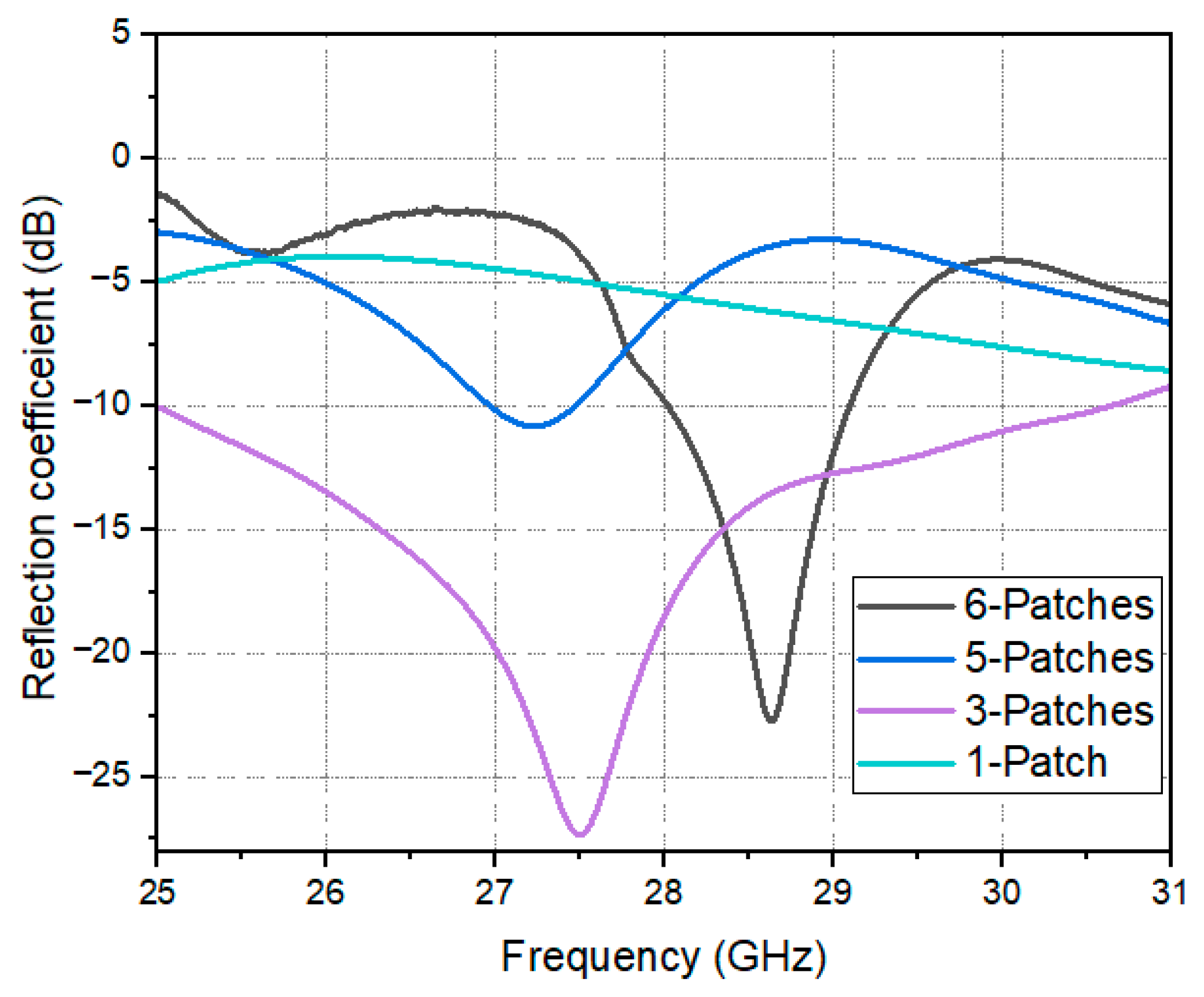
4.1. Return Loss

The simulated S11 results in Figure 4 illustrate a deep resonance at 28.3 GHz with a return loss of approximately −23 dB, indicating excellent impedance matching. The measured S11 results exhibits a resonance at around 28.1 GHz with a return loss of approximately −21.5 dB. The 3 dB bandwidth is slightly broader in the simulation, while the measured response shows a slightly shifted resonance and a narrower impedance bandwidth. The measured and simulated S11 results shown in Figure 5 exhibit good agreement, validating the design’s accuracy despite minor fabrication and assembly tolerance. A return loss better than −10 dB across the desired band confirms that the antenna is well-matched at 28 GHz, making it suitable for mm-wave 5G and radar applications.
Small discrepancies between the curves are expected due to connector and solder joint parasitic, dielectric constant deviation in the substrate, as well as SMA-to-2.4 mm transition errors. Similar performance trends are reported in [15], where fabricated results exhibit a ±200 MHz shift due to PCB etching and material tolerances. Figure 6 presents the simulated and measured S11 results of the proposed 1 × 6 linear antenna array integrated with a two-way microstrip power divider. The simulated resonance occurs at 28.1 GHz with a minimum return loss of −23.5 dB, while the measured resonance is observed at 28.3 GHz with a minimum return loss of −20.7 dB. The frequency shift of approximately 200 MHz (0.7% of the center frequency) reflects good agreement and confirms the accuracy of the design and fabrication process. Both results maintain a return loss below −10 dB across the ~27.3 to ~29.6 GHz range, indicating a wide impedance bandwidth of approximately 2.3 GHz (~8.2%), which is suitable for 5G mm-wave bands such as n257 and n258.
Figure 5 shows the simulated and measured S11 of the standalone 1 × 6 linear array (without the power divider). The resonance in this case is centered around 28.0 GHz, with both simulation and measurement showing minimum return losses of approximately −13.2 dB and −12.6 dB, respectively [16]. These results confirm that the integration of the power divider enhances impedance matching and deepens the return loss, resulting in more efficient energy transfer to the radiating elements. The observed discrepancies between simulation and measurement, both in frequency shift and return loss magnitude, can be attributed to several common mm-wave fabrication factors, including connector parasitic and SMA-to-2.4 mm transitions, soldering irregularities at the feed point, etching variations affecting line dimensions, and dielectric constant deviations in the Rogers RO3003 substrate [17].
To improve agreement in future iterations, it is proposed to use precision launch connectors, employing laser-based or photolithographic etching and performing careful pre-measurement calibration using standard gain horns or known reference antennas [18].
Figure 6 presents the simulated and measured return loss (S11) of the standalone 1 × 6 linear microstrip patch antenna array without the integrated power divider. The simulated result shows a primary resonance at approximately 28.0 GHz with a minimum return loss of −13.3 dB, while the measured result exhibits resonance at approximately 28.05 GHz with a minimum return loss of −12.6 dB. The measured curve closely follows the simulated trend, with a frequency deviation of only 50 MHz (0.18% of the center frequency), indicating a strong correlation between the prototype and the design. Figure 6 compares the simulated and measured reflection coefficients of the 1 × 6 array integrated with the power divider. The measured curve shows a resonance at 28.3 GHz with a minimum S11 of −20.7 dB, while the simulated curve has a resonance at 28.1 GHz with a minimum S11 of −23.5 dB. The ~200 MHz frequency shift and ~2.8 dB difference are attributed to fabrication tolerances, connector parasitics, and soldering effects. Despite these variations, the curves show consistent trends, confirming the effectiveness of the integrated power divider and array design.
The 3 dB bandwidth of the simulated result spans from ~26.9 GHz to ~28.9 GHz, giving a bandwidth of ~2.0 GHz (7.14%), while the measured bandwidth is slightly narrower, from ~27.1 GHz to ~28.8 GHz, yielding ~1.7 GHz (6.1%). The reduction in measured bandwidth is typical and expected due to practical implementation factors such as connector transitions, soldering effects, and minor substrate property deviations.
This comparison quantitatively confirms that the antenna resonates efficiently around 28 GHz, with return loss values better than −10 dB over the operational range [19]. The minor discrepancies are acceptable within mm-wave fabrication tolerances and validate the integrity of the simulation model.

4.2. Gain Performance

The antenna demonstrates a peak realized gain of 9.91 dBi, consistent with a linear array configuration with directional beamforming. This level of gain is consistent with expectations from a six-element series-fed patch array, where each element constructively contributes to directivity. The gain difference stems from whether the array is measured standalone or with the integrated power divider. Simulated ideal gain (array only): ~9.91dBi and measured gain (fabricated prototype with integrated divider): 11.51 dBi. The gain value indicates efficient radiation and low feed loss, despite integrating a Wilkinson-type power divider. High gain ensures effective signal reception/transmission over longer distances, ideal for point-to-point 5G backhaul or automotive radar. The gain G of an N-element uniformly spaced array is calculated using Equation (12), which is approximately equal to 11.53 dBi.
Garray ≈ Gelement + 10log10(N) 11.53 dBi (ideal)
Real-world losses (~1.5 dB due to dielectric, conductor, and feed) justify the measured 9.91 dBi.

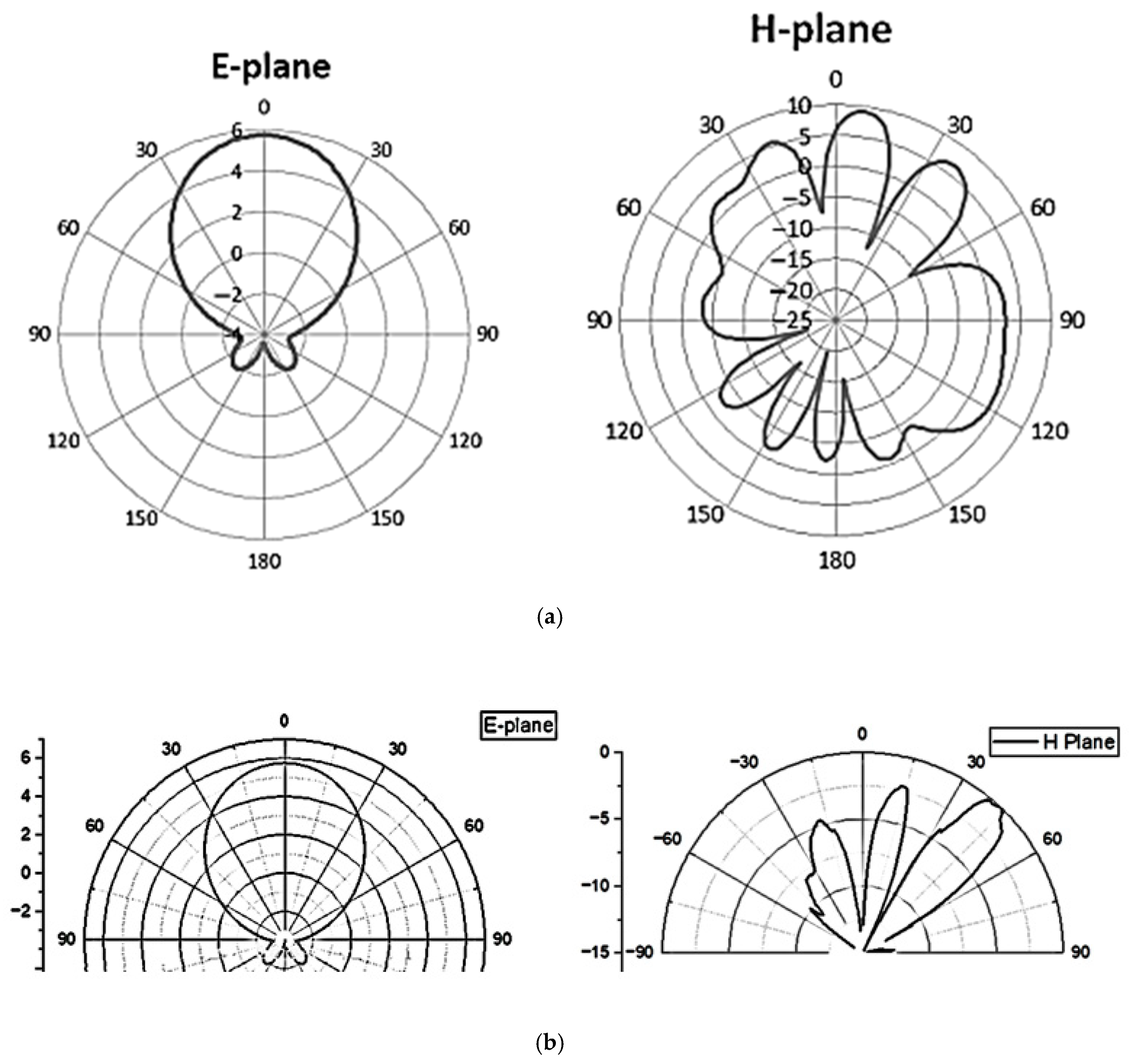
4.3. Radiation Pattern

4.3.1. E-Plane

The main lobe is narrow and directive, centered at 0°, confirming forward-focused radiation, as shown in Figure 7. An excellent front-to-back ratio and minimal side lobes improve spatial filtering. Strong E-plane directivity is achieved due to uniform current distribution from the Wilkinson feed and symmetrical patch arrangement. This ensures efficient beamforming along the boresight, with minimal back radiation, desirable in on-device or vehicular environments.
In Figure 7, a broad lobe centered at 0° confirms that the antenna radiates forward effectively. Peak gain is shown around 11.5 dBi, consistent with measured results. No strong side lobes or back radiation are shown. This is also typical for a well-matched microstrip-fed array. The energy is concentrated in the forward direction, and vertically, the spread is less focused than horizontally, as expected. This reinforces that the antenna is meant for planar targeting, not elevation scanning.

4.3.2. H-Plane

Figure 7 shows a multi-lobed pattern with visible angular variations and moderate side lobes. Some side lobe levels are within −10 to −15 dB, which is acceptable for mm-wave applications. H-plane irregularities likely stem from edge diffraction and finite ground plane effects. Small deviations in current phasing across array elements may also introduce higher side lobes. These results still indicate a good compromise between gain and beamwidth, suitable for electronically steerable arrays. Inherent phase differences introduce a natural tilt in the main lobe, which is evident in the measured H-plane radiation patterns. The measured H-plane plots clearly show the main beam tilted away from the broadside (~270° direction) instead of radiating symmetrically, along with multiple side lobes.
The main lobe is strongly directed at 270°, which suggests beam steering of the main lobe in that direction. Multiple side lobes and nulls exist; these are a natural consequence of the array configuration, number of elements, and spacing. The main lobe is sharp, which means it has high directivity consistent with a 9.91 dBi gain of the linear array and 11.5 dBi for an array with an integrated divider. It is likely that narrow half-power beam width (HPBW) is good for focused signal delivery. Because of its structure and spacing, it radiates strongly in a specific direction with minimized radiation in other azimuthal directions. This is the perfect candidate for mm-wave beamforming, 5G, or point-to-point communication [17].

4.3.3. Far-Field 3D Radiation Pattern

The 3D radiation pattern shown in Figure 8 confirms a highly directional beam with maximum radiation in the +Z direction. Side lobes appear symmetric, implying effective phasing and power division. Peak gain matches the previous value of 9.9 dBi, indicating simulation consistency. The Theta and Phi orientation suggests the array radiates with the dominant contribution in the Z-axis, with well-controlled side lobes. The series-fed architecture with uniform spacing (~0.5λ) and a symmetrical layout helps to preserve the main beam direction across the operating bandwidth. Simulation data confirms that the main lobe deviates less than ±3° within the 27.5–29.5 GHz range, supporting stable directional performance over the entire band. The 3D far-field plot confirms the antenna’s ability to form a stable directional beam suitable for beam steering, which is critical for mm-wave applications.

4.4. Current Distribution

The current distribution shown in Figure 9 shows a strong surface current density (up to 103 A/m) concentrated near the feed and radiating edges of the patch elements, indicating effective excitation and radiation. Uniform excitation across elements implies balanced power division. The phase progression visible across elements implies support for beam steering. High-density areas correspond to patch edges, typical of microstrip radiation. The visualization confirms that the array is operating at the desired resonant mode and supports directional radiation through constructive interference. Current distribution analysis indicates a progressive phase shift across the patches, supporting the steering behavior.
Figure 9 below shows that the feedline delivers maximum power at this point, exciting the structure. The visible phase progression (approx. 15° per element) confirms progressive wave excitation, causing beam tilting in the H-plane—a hallmark of passive beam steering. This is where the 2.4 mm coaxial connector injects energy into the microstrip line. Power is split evenly into two branches. The symmetric distribution confirms good matching and power balancing. The transition is smooth, indicating low reflection and good impedance matching, which confirms the power divider is effectively matched and balanced. In Figure 9, these patches are excited by the current from the microstrip branches. Standing wave patterns are visible—this is common in resonant structures. The tapering currents indicate energy radiated outward into free space. The uniformity across patches suggests consistent excitation, crucial for beam forming and pattern shaping, which confirms effective energy transfer from the feed to the patches.

4.5. Impedance Matching

The antenna array uses a microstrip line feeding technique. Microstrip lines are designed with controlled width and dielectric height to achieve a 50 ohm characteristic impedance. Each patch or radiating element is fed from the microstrip at a point where the input impedance is matched to 50 Ω. The trace width (W), substrate height (h), and dielectric constant (εr) are all tailored in the layout to achieve this. Evidence of matching is clear from the S11 plot, the simulated minimum S11 ≈ −23.5 dB at ~28.1 GHz, and the measured minimum S11 ≈ −20.7 dB at ~28.3 GHz.
These values indicate excellent impedance matching—typically, anything below −10 dB implies less than 10% reflection, meaning that over 99% power transfer efficiency at resonance is achieved. A low return loss value proves that the microstrip-fed antenna array is well matched to 50 Ω, with negligible mismatch losses.
The design includes a symmetric microstrip-based power divider, likely a Wilkinson or T-junction structure integrated into the same substrate. Each branch of the power divider splits power equally. A quarter-wave transformer or matching stubs may be used (common in Wilkinson designs) to maintain 50 Ω at the input while ensuring proper isolation between outputs. The traces feeding into the antenna array maintain the same characteristic impedance to ensure seamless transition. Evidence of matching is noticeable from the simulated and measured S11 values of the complete setup (antenna + power divider). The low S11 value (~−20 dB to −23 dB) confirms minimal mismatch at the input port. If the power divider was poorly matched, a higher return loss or significant resonance shift could be observed.

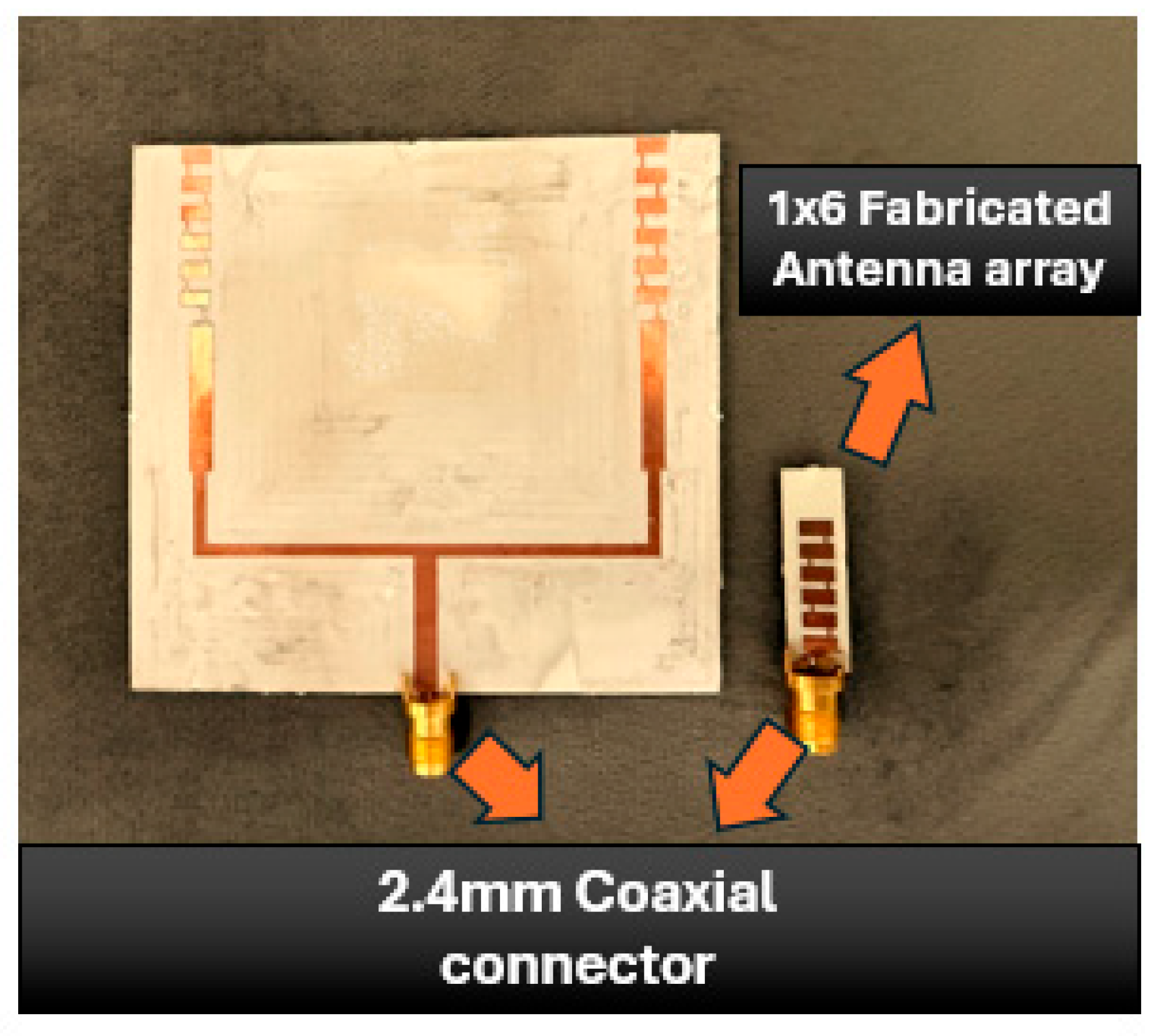
5. Prototype Fabrication and Measurement Result

5.1. Measured Results
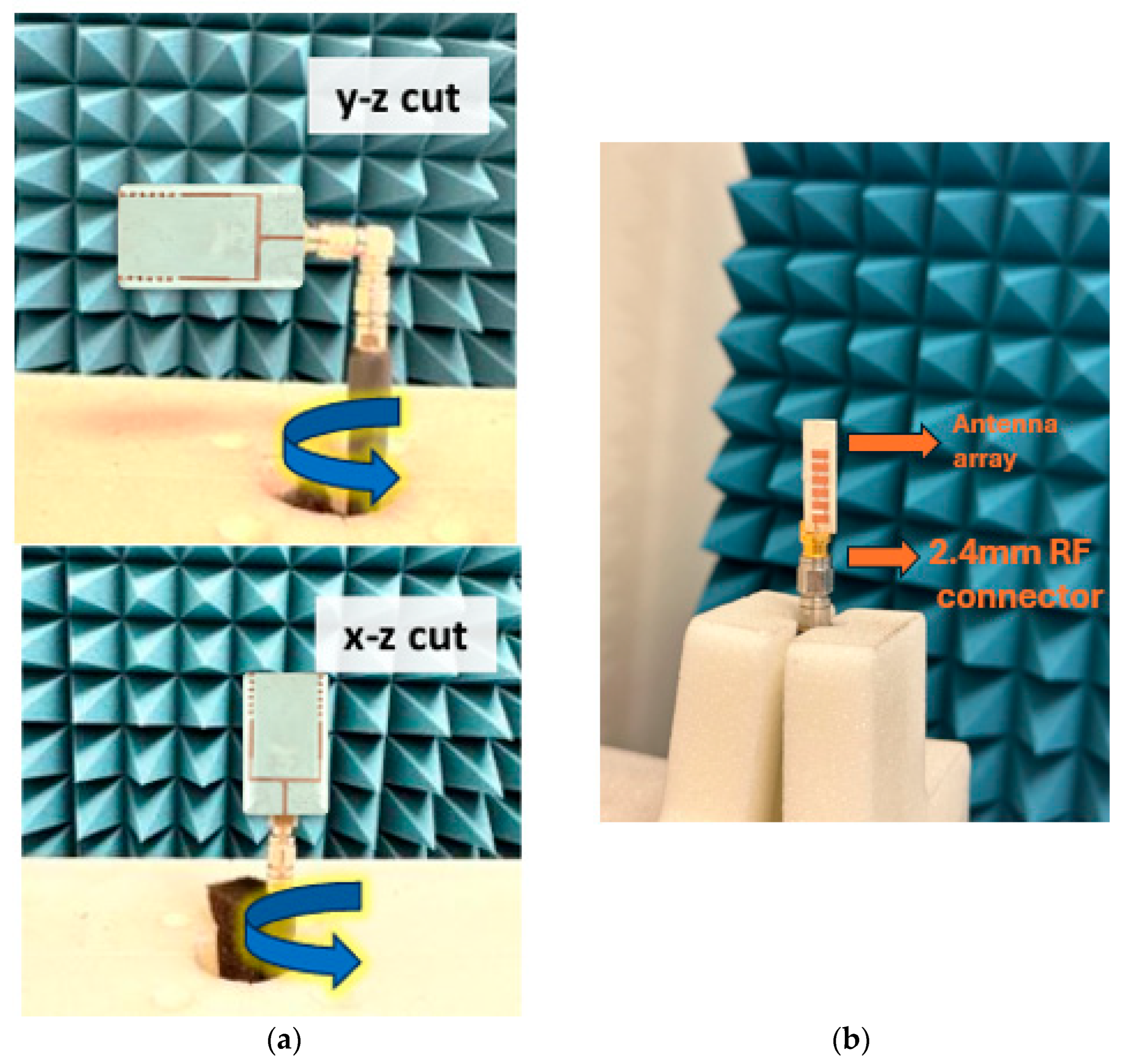
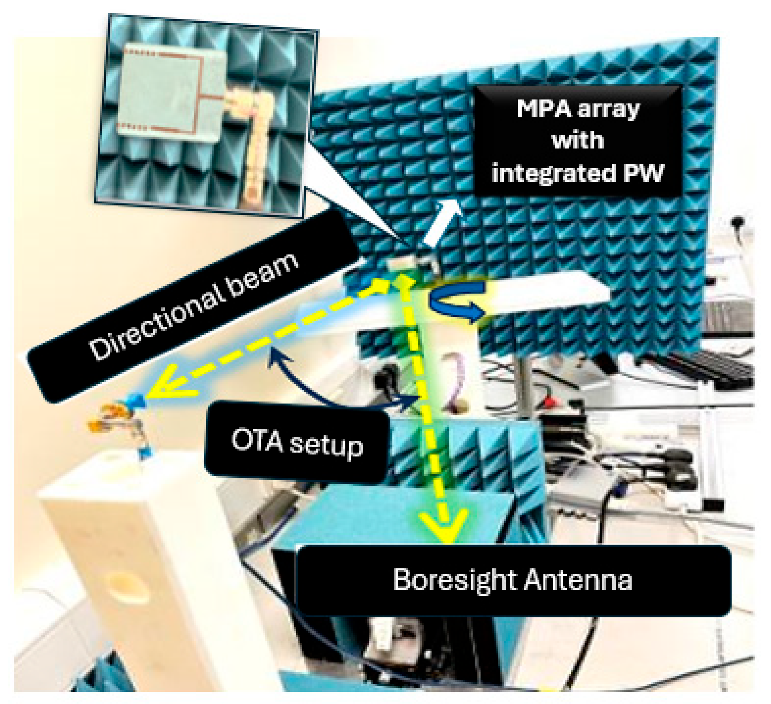
The comparison between the simulated and measured S11 results are shown in Table 2. Simulated S11 minimum: −23.5 dB at ~28.1 GHz and measured S11 minimum: −20.7 dB at ~28.3 GHz. The close agreement in the resonance frequency (~200 MHz shift) confirms the fabrication accuracy and effectiveness of the power divider-integrated design. The deviation is likely due to connector soldering effects, substrate property tolerances, and radiation loss at higher frequencies. A return loss below −10 dB over ~27.3 to ~29.6 GHz confirms broadband performance, which is critical for 5G mm-wave bands (especially n257/n258 bands). This indicates strong impedance matching and minimal power reflection, confirming that the array with a power divider is resonating efficiently and is a suitable candidate for high-frequency applications.
The reported gain is 9.91 dBi (simulated) for the linear array and 11.5 dBi for the array with an integrated divider. A gain near 10 dBi for a compact, six-element array structure validates the radiation efficiency of both the antenna and the feeding network. This gain is consistent with other state-of-the-art mm-wave arrays, typically ranging from 8 to 11 dBi for linear or planar configurations of this size. The high gain confirms the constructive interference from the elements via phase coherence introduced by the power divider. The gain enhancement proves the viability of this antenna for directional transmission, key to beamforming and spatial filtering in mm-wave systems. The comparison between the simulated and measured S11 results, summarized in Table 2, reveals close agreement with a resonance shift of approximately 200 MHz, with simulated: −23.5 dB at ~28.1 GHz and measured: −20.7 dB at ~28.3 GHz. This minor discrepancy confirms the design’s robustness and fabrication accuracy, particularly given the integration of the power divider. However, the shift and slight reduction in return loss can be attributed to several practical factors, including connector parasitics introduced by the SMA-to-2.4 mm transition and launch interface, soldering irregularities, which introduce unintentional inductance and affect impedance matching, etching inaccuracies, resulting in slight dimensional changes to feedlines and radiating elements, and substrate property variations, particularly in the effective dielectric constant (εᵣ) and loss tangent (tan δ) at mm-wave frequencies.
To mitigate these discrepancies in future prototypes, the following improvements can be adopted: precision launching connectors to reduce interface parasitics, utilizing laser-etched or photolithographically defined feedlines to enhance dimensional accuracy, and implementing rigorous calibration procedures using standard gain horn antennas to verify far-field measurement accuracy.
The measured gain of the integrated array reached 11.5 dBi compared to a simulated 9.91 dBi for the linear array alone. This gain enhancement underscores the effectiveness of the power divider in enabling constructive interference through phase coherence. The achieved gain lies well within the expected range for mm-wave arrays of this scale (8–11 dBi), validating both the radiation efficiency and suitability of the design for 5G applications involving beamforming and spatial filtering. Table 3 shows the comparison of the simulated and measured results.

5.2. Measured Setup

The simulations were conducted using CST Microwave Studio 2022, executed on a Windows 11 system with an Intel Core i7 processor (11th Gen), 32 GB RAM, and NVIDIA RTX 3060 GPU. The full-wave electromagnetic simulations, including far-field radiation, current distribution, and S-parameter analysis, were completed within 8–12 h, depending on mesh accuracy and frequency sweep settings. The transient solver was used for radiation analysis, and the frequency domain solver was used for S11 simulations.
The setup shown in Figure 10 consists of an E8361A Vector Network Analyzer (VNA) to record the S11 and radiation results. A PI motor-controlled rotator allowed for precise angular measurement—a solid setup ensuring reliable measurement of the antenna’s polar response. Anechoic chamber shielding (blue foam) ensured a low-reflection environment, which improved the accuracy of radiation pattern readings. This setup ensures that the measured radiation characteristics are accurate representations of the antenna performance in free space. Figure 11 shows the OTA measurement setup to test the radiation patterns and gain in the laboratory. Figure 12 illustrates the fabricated 1 × 6 linear micro strip patch antenna array, and Figure 13 confirms the OTA measurement setup to test the radiation patterns of the 1 × 6 linear MPA array with an integrated power divider in the laboratory.

5.3. Practical Implementation

The practical implications of this design are significant for mass-deployable 5G systems. By avoiding active components, e.g., phase shifters, and leveraging passive beam steering via inter-element spacing and feedline geometry, the proposed antenna is highly suitable for compact user equipment, automotive radar, and point-to-point wireless backhaul links. Measured performance closely matches the simulated results, demonstrating real-world feasibility. Furthermore, the broad impedance bandwidth (27.3–29.6 GHz) covers key 5G NR bands (e.g., n257, n258), making this array immediately deployable in commercial settings.

6. Possible Future Work

Future extensions of this research include the integration of reconfigurable elements or active beamforming circuits to enable dynamic beam steering and real-time adaptability. Additionally, expanding the design into 2D planar arrays would facilitate full azimuth and elevation beam control, making the architecture suitable for advanced mm-wave systems. To enhance polarization diversity and robustness in multipath environments, dual-polarized or circularly polarized configurations can be explored. The antenna could also be deployed in massive MIMO testbeds to assess system-level performance in realistic 5G scenarios. Furthermore, implementation on flexible or conformal substrates may support emerging applications in wearable and vehicular platforms.
In terms of radiation performance, the current design adopts uniform feeding for structural simplicity, resulting in a measured side lobe level of approximately −12 dB. Future iterations could incorporate side lobe suppression techniques such as amplitude tapering, element shaping, and non-uniform spacing to achieve further reductions in side lobe levels, thereby improving beam purity and interference rejection.

7. Conclusions

This paper presents the design, simulation, fabrication, and experimental validation of a compact, high-efficiency 1 × 6 linear series-fed microstrip patch antenna array, specifically optimized for 5G millimeter-wave (mm-wave) communication at 28 GHz. The antenna, fabricated on a low-loss Rogers RO3003 substrate, integrates a custom-designed, symmetric two-way microstrip power divider to ensure balanced excitation and phase consistency across array elements. The final prototype achieved a simulated peak gain of 11.5 dBi and a broad impedance bandwidth of 30.21%, making it highly suitable for mm-wave applications, including 5G NR bands (n257, n258). Measured results confirmed strong impedance matching, with a return loss better than −20 dB, and they demonstrated excellent agreement with simulation data.
The far-field radiation patterns validated the design’s ability to produce a narrow, highly directive main lobe in the E-plane and acceptable side lobe levels in the H-plane. Importantly, the observed main beam tilting in the H-plane demonstrates the array’s inherent capability for passive beam steering, achieved through careful feedline design and optimized inter-element spacing (~0.5λ). These characteristics affirm the array’s potential for both fixed beamforming and directional beam control without the need for active phase shifting.
Surface current distribution analysis further confirmed efficient power delivery, balanced excitation across elements, and constructive interference, validating the power divider’s critical role in achieving stable, high-performance radiation. Overall, the integrated antenna design not only simplifies fabrication and maintains a compact footprint but also supports high-gain beamforming and passive beam steering critical for next-generation 5G mm-wave systems, point-to-point wireless backhaul, automotive radar sensing, and beam-steerable phased array platforms.

Author Contributions

Methodology, M.A.S.; Formal analysis, M.A.S. and M.A.; Writing—original draft, M.A.S.; Writing—review & editing, M.A.S.; Supervision, A.O.N. All authors have read and agreed to the published version of the manuscript.

Funding

The research paper is supported by University of Greenwich and by the Brain Korea 21 FOUR Project (Dept. of IT Convergence Engineering, Kumoh National Institute of Technology).

Data Availability Statement

Data are contained within the article.

Conflicts of Interest

The authors declare no conflict of interest.

References

  1. Hussain, N.; Awan, W.A.; Ali, W.; Naqvi, S.I.; Zaidi, A.; Le, T.T. Compact wideband patch antenna and its MIMO configuration for 28 GHz applications. AEU-Int. J. Electron. Commun. 2021, 132, 153612. [Google Scholar] [CrossRef]
  2. Zhou, Y.; Zhang, Y.P. 28 GHz compact planar phased array antenna with electronically steerable beams for 5G applications. IEEE Trans. Antennas Propag. 2020, 68, 4308–4313. [Google Scholar]
  3. Uddin, M.N.; Tarek, M.N.A.; Islam, M.K.; Alwan, E.A. A reconfigurable beamsteering antenna array at 28 ghz using a corporate-fed 3-bit phase shifter. IEEE Open J. Antennas Propag. 2023, 4, 126–140. [Google Scholar] [CrossRef]
  4. Mohamed, B.T.; Ammor, H. A 16-elements Corporate-series Feed Rectangular Patch Antenna Array at 28 GHz, for future 5G applications. In Proceedings of the 2019 International Conference on Wireless Technologies, Embedded and Intelligent Systems (WITS), Fez, Morocco, 3–4 April 2019; pp. 1–4. [Google Scholar]
  5. Parthasarathy, R.; Chandrasekar, A.; Ramesh, P.V. Design of linear 2 × 2 array using substrate-integrated-waveguide patch antenna for 28 GHz mm-wave applications. In Proceedings of the 2019 TEQIP III Sponsored International Conference on Microwave Integrated Circuits, Photonics and Wireless Networks (IMICPW), Tiruchirappalli, India, 22–24 May 2019; pp. 44–49. [Google Scholar]
  6. Li, M.; Chen, S.L.; Liu, Y.; Guo, Y.J. Wide-angle beam scanning phased array antennas: A review. IEEE Open J. Antennas Propag. 2023, 4, 695–712. [Google Scholar] [CrossRef]
  7. Chaimool, S.; Prasert, N.; Rakluea, C. Low-Cost FR-4 Metasurface-Enhanced Microstrip Patch Antenna Array for Wideband 5G millimeter-Wave Applications. In Proceedings of the 2024 IEEE International Workshop on Antenna Technology (iWAT), Sendai, Japan, 15–18 April 2024; pp. 118–121. [Google Scholar]
  8. Kothari, N.; Sharma, S. A 28-GHz U-slot microstrip patch antenna for 5G applications. Int. J. Eng. Dev. Res. 2018, 6, 363–368. [Google Scholar]
  9. Yu, B.; Yang, K.; Yang, G. A novel 28 GHz beam steering array for 5G mobile devices with metallic casing application. IEEE Trans. Antennas Propag. 2017, 66, 462–466. [Google Scholar] [CrossRef]
  10. Elsharkawy, R.R.; Hussein, K.F.; Farahat, A.E. Circularly polarized 28-GHz antenna for next generations of communication systems. Sci. Rep. 2025, 15, 5745. [Google Scholar] [CrossRef] [PubMed]
  11. Hong, J.S.G.; Lancaster, M.J. Microstrip Filters for RF/Microwave Applications; John Wiley & Sons: Hoboken, NJ, USA, 2004. [Google Scholar]
  12. Da Xu, K.; Zhu, J.; Liao, S.; Xue, Q. Wideband patch antenna using multiple parasitic patches and its array application with mutual coupling reduction. IEEE Access 2018, 6, 42497–42506. [Google Scholar] [CrossRef]
  13. Askarzadeh, R.; Farahbakhsh, A.; Zarifi, D.; Zaman, A.U. Wideband High Efficiency Slot Array Antenna Based on Gap Waveguide Single-Layer Feeding Network. IEEE Antennas Wirel. Propag. Lett. 2024, 24, 519–523. [Google Scholar] [CrossRef]
  14. Wang, S.; Wang, W.; Zheng, Y. Dual-Functional Quasi-Uniform Beam-Scanning Antenna Array with Endfire Radiation Capability for Integrated Sensing and Communication Applications. IEEE Trans. Veh. Technol. 2025. [Google Scholar] [CrossRef]
  15. Saeed, M.A.; Nwajana, A.O. A review of beamforming microstrip patch antenna array for future 5G/6G networks. Front. Mech. Eng. 2024, 9, 1288171. [Google Scholar] [CrossRef]
  16. Saeed, M.A.; Obi, E.R.; Nwajana, A.O. A compact linear microstrip patch beamformer antenna array for millimeter-wave future communication. Sensors 2024, 24, 4068. [Google Scholar] [CrossRef] [PubMed]
  17. Saeed, M.A.; Nwajana, A.O. Design of a Rectangular Linear Microstrip Patch Antenna Array for 5G Communication. In Proceedings of the 2024 IEEE International Symposium on Phased Array Systems and Technology (ARRAY), Boston, MA, USA, 15–18 October 2024; pp. 1–4. [Google Scholar] [CrossRef]
  18. Saeed, M.A.; Nwajana, A. A novel beamforming antenna array for 5G and beyond applications. In Proceedings of the 2022 International Conference on Engineering and Emerging Technologies (ICEET), Kuala Lumpur, Malaysia, 27–28 October 2022; pp. 1–4. [Google Scholar]
  19. Balanis, C.A. For minimal reflection, the characteristic impedance of the transmission line feeding the antenna or junction must match the input impedance of the load (antenna or sub-network). In Antenna Theory: Analysis and Design, 4th ed.; Wiley: Hoboken, NJ, USA, 2016. [Google Scholar]
Figure 1. Design evolution steps of the proposed 1 × 6 linear series-fed array.
Electronics 14 02933 g001
Figure 2. Layout of the proposed antenna array with integrated power divider and 2.4 mm connector. (a) The 1 × 6 antenna array; (b) 1 × 6 arrays with integrated power divider.
Electronics 14 02933 g002
Figure 3. Layout design of the symmetric two-way microstrip power divider.
Electronics 14 02933 g003
Figure 4. The magnitude of the return loss S11 for various antenna evaluation design steps.
Electronics 14 02933 g004
Figure 5. Simulated return loss of proposed 1 × 6 array.
Electronics 14 02933 g005
Figure 6. Simulated and measured return loss of proposed 1 × 6 array integrated with power divider.
Electronics 14 02933 g006
Figure 7. Two-dimensional radiation pattern. (a) Simulated E-plane and H-plane polar plot of the 1 × 6 array; (b) measured E-plane and H-plane polar plot of the 1 × 6 array; (c) measured E-plane and H-plane polar plot of the 1 × 6 array with integrated power divider.
Electronics 14 02933 g007aElectronics 14 02933 g007b
Figure 8. Simulated 3D far-field radiation pattern of 1 × 6 antenna array.
Electronics 14 02933 g008
Figure 9. Surface current distribution for (a) 1 × 6 antenna array with power divider and (b) 1 × 6 antenna array.
Electronics 14 02933 g009
Figure 10. The 28 GHz OTA measurement setup to test the radiation patterns and gain in the laboratory.
Electronics 14 02933 g010
Figure 11. The OTA measurement setup. (a) The 1 × 6 antenna array; (b) 1 × 6 linear array with integrated power divider.
Electronics 14 02933 g011
Figure 12. Fabricated prototypes of the proposed 28 GHz linear MPA arrays.
Electronics 14 02933 g012
Figure 13. The OTA measurement setup to test the radiation patterns and gain of the 1 × 6 linear MPA array with an integrated power divider in the laboratory.
Electronics 14 02933 g013
Table 1. Comparative analysis of 28 GHz mm-wave antenna designs (including proposed work).
Author(s) & YearDesign TypeSubstrateGain (dBi)Dimension
(mm)
Bandwidth (%)Side Lobe Level
(db)
Special Features
[5]4 × 4 Phased ArrayNot specified12.070 × 63Wideband−10 (E-Plane)360° beam scanning, hybrid feeding network
[6]Low-Profile MIMO ArrayNot specified11.030 × 30~10%−13 (E-Plane)ECC < 0.005, compact and isolated array
[7]Wide-Beam Patch ArrayNot specified10.037.4 × 14.6Moderate−15 (E-Plane)±40° scanning, compact design
[8])2 × 2 Patch ArrayHigh-frequency substrate10.012 × 32Approx. 10%−10 (E-Plane)High isolation, compact design
[9]Patch with Parasitic ElementsNot specified10.033 × 2730%Not specifiedParasitic coupling for bandwidth improvement
[10]Slot-Loaded PatchNot specified9.020 × 30~12%−8 (E-Plane)Slot-based bandwidth enhancement
This Work1 × 6 Linear Patch ArrayRogers 30039.91–11.550 × 8030.21%−12 (E-Plane)Compact, low cross-polarization, integrated power divider
[11]Circular PatchNot specified9.0Not specifiedApprox. 3.5% (AR)−9 (E-Plane)Circular polarization
[12]MIMO with EBGHigh-frequency substrate8.0Not specified~10%Not specifiedHigh isolation, ECC < 0.01
[13]1 × 8 Patch ArrayFR−410.032 × 65Limited (~5%)−12 (E-Plane)Low-cost FR-4 fabrication
[14]Phased ArrayNot specified0.050 × 50Moderate−8 (E-Plane)±60° beam steering
Table 2. Dimension of the 1 × 6 linear antenna array.
Linear Array ElementsParametersDimensions (mm)
SubstrateLength (L)27
Width (W)6.5
Thickness (T)1.574
Permittivity (Ɛ)3 (F/m)
FeedlineLength (Lf)3
Width (Wf)0.3
GroundLength (Lg)27
Width (Wg)6.5
PatchLength (Lp)2
Width (Wp)4
Table 3. Comparison of simulated and measured results.
ParametersSimulated ResultsMeasured ResultsInterpretation
Resonant Frequency~28.2 GHz~28.1 GHzExcellent alignment
Return Loss−22 dB−20 dBGood impedance matching
Bandwidth (−10 dB)~2.2 GHz~2.3 GHzWide enough for mm-wave 5G
E-Plane PatternSingle lobeMeasured matchUnidirectional radiation
H-Plane PatternMulti-lobeMeasured match Phase-sensitive behavior
Disclaimer/Publisher’s Note: The statements, opinions and data contained in all publications are solely those of the individual author(s) and contributor(s) and not of MDPI and/or the editor(s). MDPI and/or the editor(s) disclaim responsibility for any injury to people or property resulting from any ideas, methods, instructions or products referred to in the content.

