A Novel Two-Stage Power Conversion Method Suitable for 1MHz-LDC of Electric Vehicles †
Abstract
1. Introduction
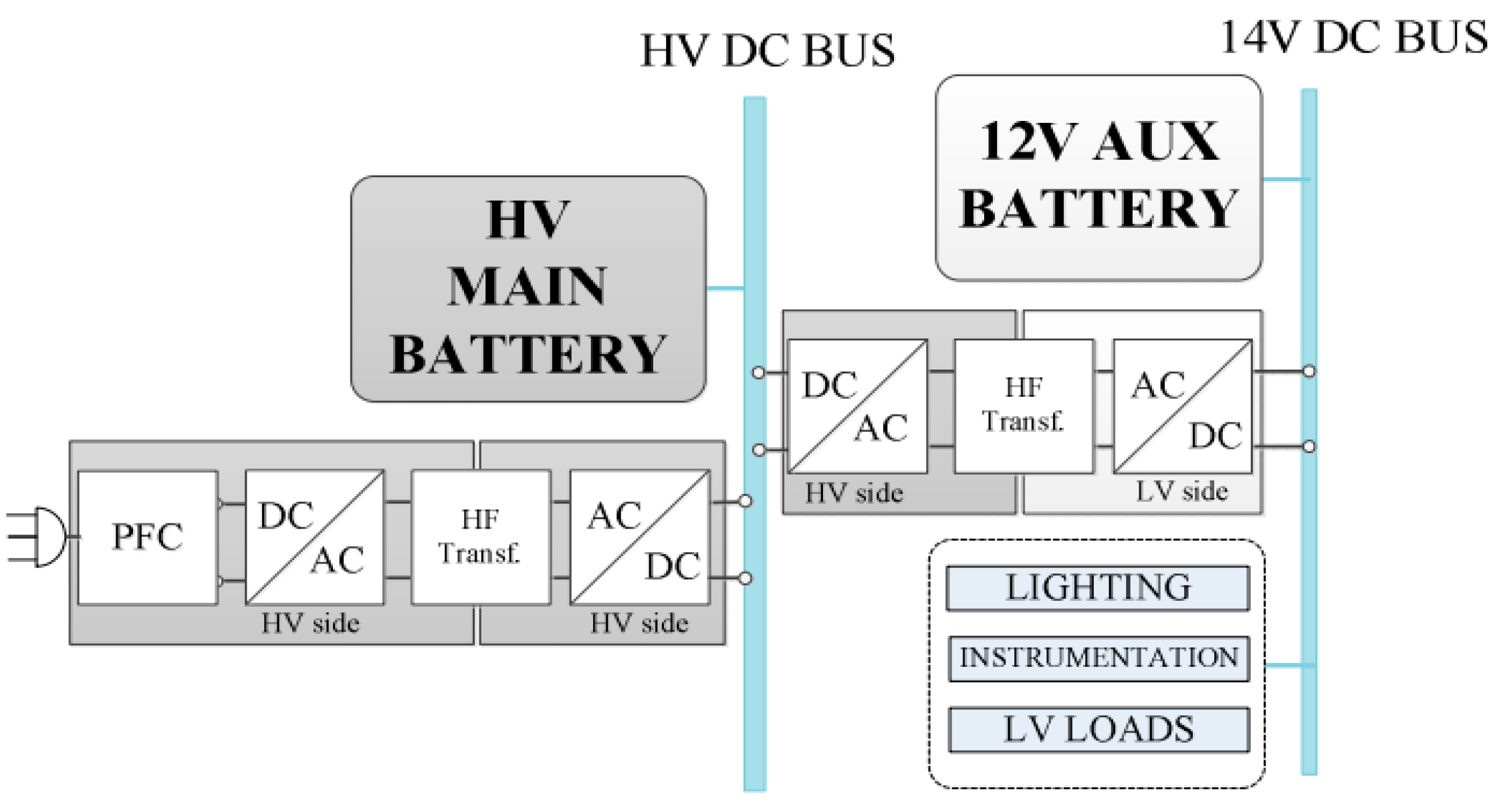
2. Operating Principle of the Proposed Converter
2.1. Brief Introduction of Operating Principle
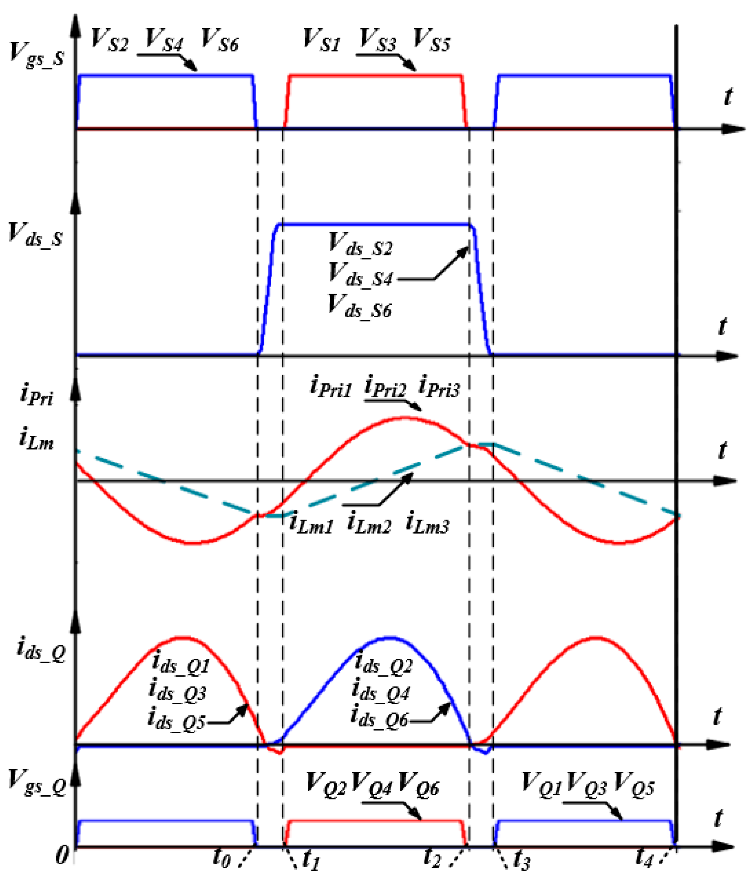
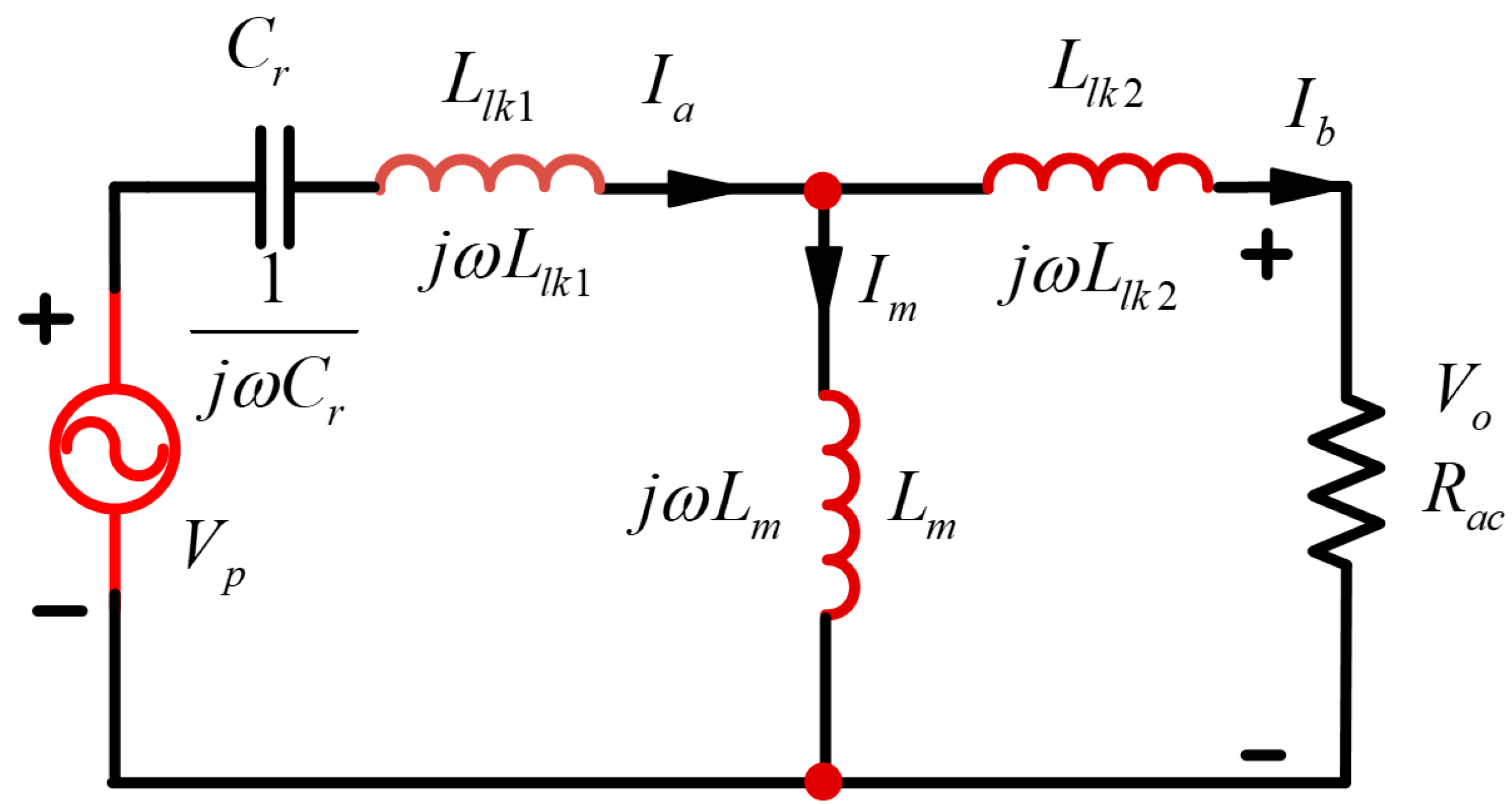
2.2. Operating Principle
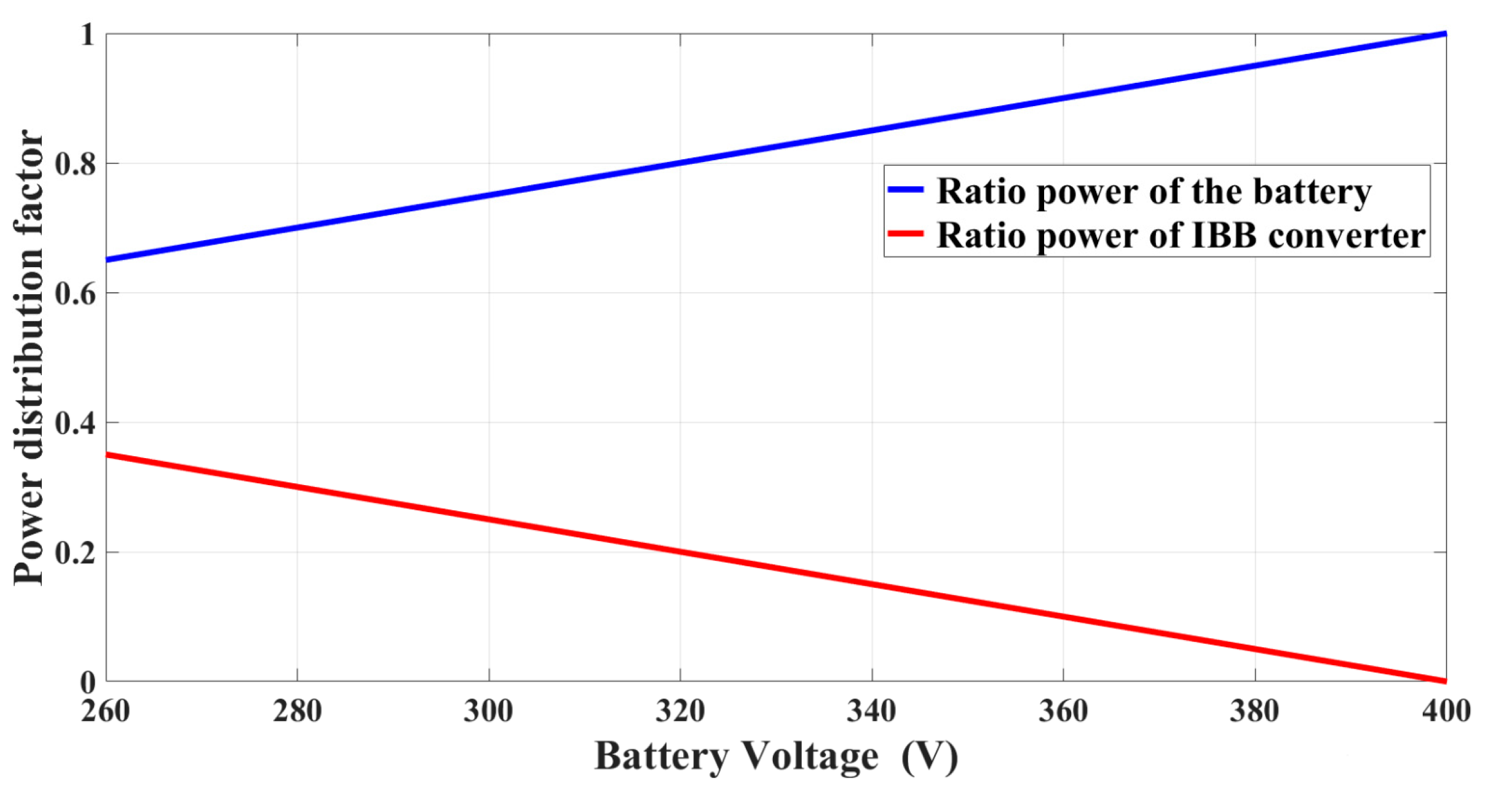
2.3. Power Flow Analysis
2.4. Load Current Balancing in Multiphase Parallel LLC Converters
3. Design Considerations
3.1. IBB Stage Parameter Design
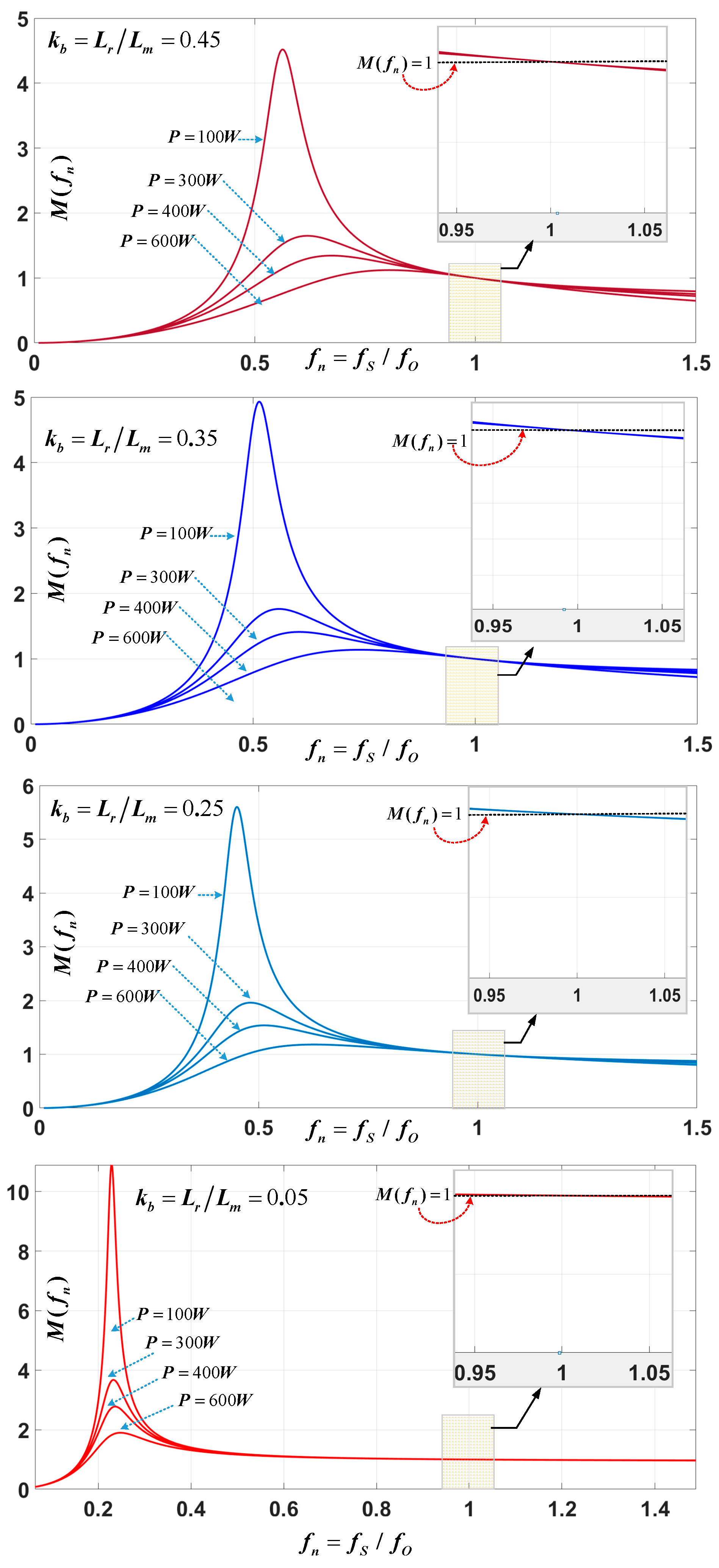
3.2. LLC Parameters Design
- As the magnetizing current constitutes a substantial portion of the total resonant current, the reactive power increases, thereby deteriorating the power factor.
- Elevated magnetizing current results in higher turn-off current through the primary switches, which in turn increases the switching losses.
3.3. Planar Transformer Design Consideration
- (1)
- Planar transformers suffer from high parasitic capacitance; the effects of parasitic capacitance have been discussed in several studies [21,22,23,24]. Overlapping PCB trace and high voltage gradient is the main reason which creates the parallel plate capacitors. Equation (16) shows that the higher parasitic winding capacitance requires higher magnetizing current at the transformer input, resulting in a higher loss. In addition, high intra-winding capacitance of planar transformer distorts the waveforms and impacts the voltage conversion ratio and light load regulation [23,24].
- (2)
- When using a traditional planar transformer with low frequency and low output, the copper poles of the main PCB are generally used to connect the added-side windings. But, this arrangement suffers greatly from termination losses because of proximity effect and skin effect, which leads to most of the current being near the edges. This results in high heat and more losses around the edge terminals. The key reason behind this problem is that it leads to noticeable power loss in the high-power, high-frequency planar transformer [25].
4. Experimental Results
- (1)
- Cascode GaN HEMT has a much smaller Qg, which not only reduces the driving loss but also increases efficiency.
- (2)
- Achieving very low junction capacitance may incur higher cost, but it enables shorter deadtime or reduced magnetizing current to realize soft-switching ZVS both of which significantly improve converter efficiency at a 1 MHz operating frequency.
5. Conclusions
Author Contributions
Funding
Data Availability Statement
Conflicts of Interest
References
- Rong, R.; Zeljkovic, S. A 2kW, 100kHz high speed IGBT based HV-LV DC/DC converter for electric vehicle. In Proceedings of the 2014 IEEE Conference and Expo Transportation Electrification Asia-Pacific (ITEC Asia-Pacific), Beijing, China, 31 August–3 September 2014. [Google Scholar]
- Hasan, S.M.N.; Anwar, M.N.; Teimorzadeh, M.; Tasky, D.P. Features and challenges for Auxiliary Power Module (APM) design for hybrid/electric vehicle applications. In Proceedings of the 2011 IEEE Vehicle Power and Propulsion Conference, Chicago, IL, USA, 6–9 September 2011; pp. 1–6. [Google Scholar] [CrossRef]
- Galek, M.; Mondal, G. Modular DC/DC converter with improved efficiency for electric vehicles applications. In Proceedings of the 2014 IEEE Applied Power Electronics Conference and Exposition—APEC 2014, Fort Worth, TX, USA, 16–20 March 2014; pp. 1958–1965. [Google Scholar]
- Tuan, T.M.; Choi, W. A novel two-stage power conversion method suitable for LDCs of the electric vehicles. In Proceedings of the 2019 10th International Conference on Power Electronics and ECCE Asia (ICPE 2019-ECCE Asia), Busan, Republic of Korea, 27–30 May 2019; pp. 1–7. [Google Scholar]
- Pang, Z.; Ren, X.; Xiang, J.; Chen, Q.; Ruan, X.; Chen, W. High-frequency DC-DC converter in electric vehicle based on GaN transistors. In Proceedings of the 2016 IEEE Energy Conversion Congress and Exposition (ECCE), Milwaukee, WI, USA, 18–22 September 2016; pp. 1–7. [Google Scholar] [CrossRef]
- Lu, B.; Liu, W.; Liang, Y.; Lee, F.C.; van Wyk, J.D. Optimal design methodology for LLC resonant converter. In Proceedings of the Twenty-First Annual IEEE Applied Power Electronics Conference and Exposition, 2006. APEC ‘06., Dallas, TX, USA, 19–23 March 2006. [Google Scholar]
- Fu, D.; Lu, B.; Lee, F.C. 1MHz High Efficiency LLC Resonant Converters with Synchronous Rectifier. In Proceedings of the 2007 IEEE Power Electronics Specialists Conference, Orlando, FL, USA, 17–21 June 2007; pp. 2404–2410. [Google Scholar]
- Wu, X.; Chen, H.; Qian, Z. 1-MHz LLC Resonant DC Transformer (DCX) With Regulating Capability. IEEE Trans. Ind. Electron. 2016, 63, 2904–2912. [Google Scholar] [CrossRef]
- Park, H.; Jung, J. PWM and PFM Hybrid Control Method for LLC Resonant Converters in High Switching Frequency Operation. IEEE Trans. Ind. Electron. 2017, 64, 253–263. [Google Scholar] [CrossRef]
- Fu, D.; Liu, Y.; Lee, F.C.; Xu, M. A novel driving scheme for synchronous rectifiers in LLC resonant converters. IEEE Trans. Power Electron. 2009, 24, 1321–1329. [Google Scholar] [CrossRef]
- Feng, W.; Lee, F.C.; Mattavelli, P.; Huang, D. A universal adaptive driving scheme for synchronous rectification in LLC resonant converters. IEEE Trans. Power Electron. 2012, 27, 3775–3781. [Google Scholar] [CrossRef]
- Kim, K.W.; Youn, H.S.; Baek, J.I.; Jeong, Y.; Moon, G.W. Analysis on Synchronous Rectifier Control to Improve Regulation Capability of High-Frequency LLC Resonant Converter. IEEE Trans. Power Electron. 2017, 33, 1–10. [Google Scholar] [CrossRef]
- Wang, H.; Chen, Y.; Qiu, Y.J.; Fang, P.; Zhang, Y.; Wang, L.L. Common Capacitor Multiphase LLC Converter With Passive Current Sharing Ability. IEEE Trans. Power Electron. 2018, 33, 370–387. [Google Scholar] [CrossRef]
- Hu, Z.; Qiu, Y.; Wang, L.; Liu, Y.-F. An interleaved LLC resonant converter operating at constant switching frequency. In Proceedings of the 2012 IEEE Energy Conversion Congress and Exposition (ECCE), Raleigh, NC, USA, 15–20 September 2012; pp. 3541–3548. [Google Scholar]
- Wu, H.; Zhan, X.; Xing, Y. Interleaved LLC resonant converter with hybrid rectifier and variable-frequency plus phase-shift control for wide output voltage range applications. IEEE Trans. Power Electron. 2017, 32, 4246–4257. [Google Scholar] [CrossRef]
- Figge, H.; Grote, T.; Froehleke, N.; Boecker, J.; Ide, P. Paralleling of LLC resonant converters using frequency controlled current balancing. In Proceedings of the 2008 IEEE Power Electronics Specialists Conference, Rhodes, Greece, 15–19 June 2008; pp. 1080–1085. [Google Scholar]
- Huang, X.; Liu, Z.; Li, Q.; Lee, F.C. Evaluation and Application of 600 V GaN HEMT in Cascode Structure. IEEE Trans. Power Electron. 2014, 29, 2453–2461. [Google Scholar] [CrossRef]
- Hariya, A.; Yanagi, H.; Ishizuka, Y.; Matsuura, K.; Tomioka, S.; Ninomiya, T. 5MHz PWM-controlled current-mode resonant DC–DC converter with GaN-FETs. In Proceedings of the 2014 IEEE Applied Power Electronics Conference and Exposition—APEC 2014, Fort Worth, TX, USA, 16–20 March 2014; pp. 1426–1432. [Google Scholar]
- Reusch, D.; Strydom, J. Evaluation of Gallium Nitride Transistors in High Frequency Resonant and Soft-Switching DC–DC Converters. IEEE Trans. Power Electron. 2015, 30, 5151–5158. [Google Scholar] [CrossRef]
- Zhang, W.; Wang, F.; Costinett, D.J.; Tolbert, L.M.; Blalock, B.J. Investigation of Gallium Nitride Devices in High-Frequency LLC Resonant Converters. IEEE Trans. Power Electron. 2017, 32, 571–583. [Google Scholar] [CrossRef]
- Lu, J.; Dawson, F. Characterizations of High Frequency Planar Transformer With a Novel Comb-Shaped Shield. IEEE Trans. Magn. 2011, 47, 4493–4496. [Google Scholar] [CrossRef]
- Ouyang, Z.; Thomsen, O.C.; Andersen, M.A.E. Optimal Design and Tradeoff Analysis of Planar Transformer in High-Power DC–DC Converters. IEEE Trans. Ind. Electron. 2012, 59, 2800–2810. [Google Scholar] [CrossRef]
- Pahlevaninezhad, M.; Hamza, D.; Jain, P.K. An Improved Layout Strategy for Common-Mode EMI Suppression Applicable to High-Frequency Planar Transformers in High-Power DC/DC Converters Used for Electric Vehicles. IEEE Trans. Power Electron. 2014, 29, 1211–1228. [Google Scholar] [CrossRef]
- Saket, M.A.; Shafiei, N.; Ordonez, M. LLC Converters With Planar Transformers: Issues and Mitigation. IEEE Trans. Power Electron. 2017, 32, 4524–4542. [Google Scholar] [CrossRef]
- Fu, D.; Lee, F.C.; Wang, S. Investigation on transformer design of high frequency high efficiency dc-dc converters. In Proceedings of the 2010 Twenty-Fifth Annual IEEE Applied Power Electronics Conference and Exposition (APEC), Palm Springs, CA, USA, 21–25 February 2010; pp. 940–947. [Google Scholar]
- Yan, C.; Li, F.; Zeng, J.; Liu, T.; Ying, J. A Novel Transformer Structure for High power, High Frequency converter. In Proceedings of the 2007 IEEE Power Electronics Specialists Conference, Orlando, FL, USA, 17–21 June 2007; pp. 214–218. [Google Scholar]
- Huang, D.; Ji, S.; Lee, F.C. LLC Resonant Converter With Matrix Transformer. IEEE Trans. Power Electron. 2014, 29, 4339–4347. [Google Scholar] [CrossRef]
- Mu, M.; Lee, F.C. Design and Optimization of a 380–12 V High-Frequency, High-Current LLC Converter With GaN Devices and Planar Matrix Transformers. IEEE J. Emerg. Sel. Top. Power Electron. 2016, 4, 854–862. [Google Scholar]
- Fei, C.; Lee, F.C.; Li, Q. High-Efficiency High-Power-Density LLC Converter With an Integrated Planar Matrix Transformer for High-Output Current Applications. IEEE Trans. Ind. Electron. 2017, 64, 9072–9082. [Google Scholar] [CrossRef]
- Singh, A.R.; Suresh, K.; Parimalasundar, E.; Kumer, B.H.; Bajaj, M.; Tuka, M.B. Design and performance evaluation of a multi-load and multi-source DC-DC converter for efficient electric vehicle power systems. Sci. Rep. 2024, 14, 25718. [Google Scholar] [CrossRef] [PubMed]
- Yang, G.; Dubus, P.; Sadarnac, D. Double-phase high-efficiency, wide load range high-voltage/low-voltage LLC DC/DC converter for electric/hybrid vehicles. IEEE Trans. Power Electron. 2015, 30, 1876–1886. [Google Scholar] [CrossRef]
- Guan, Q.; Rubino, L.; Wang, Z.; Bozhko, S. Design and implementation of GaN-based dual-active-bridge DC/DC converters. IEEE Trans. Ind. Electron. 2020, 67, 9982–9992. [Google Scholar]






| Parameters | Symbols | Values |
|---|---|---|
| Maximum output power | 1.8 [kW] | |
| Input voltage | 260–400 [V] | |
| Output voltage | 14 [V] | |
| Switching frequency | 1 [MHz] |
| Parameters | Symbols | Values |
|---|---|---|
| Inductor | L1 | 350 [µH] |
| Output capacitor | C1 | 100 [µF] |
| Input voltage | Vin | 260–400 [V] |
| Output voltage | Vdc,min~Vdc,max | 0–140 [V] |
| Switching frequency | fsw_ibb | 100 [kHz] |
| Maximum output power | PIBB | 650 [W] |
| Parameters | Symbols | Values |
|---|---|---|
| Maximum power | 600 [W] | |
| Input voltage | 400 [V] | |
| Output voltage | 14 [V] | |
| Switching frequency | 1 [MHz] | |
| Turn ratio | n | 16:1 |
| Parameters | Symbols | Values |
|---|---|---|
| Resonant capacitor | Cr | ] |
| Leakage inductance | Llk = Lr | ] |
| Magnetizing inductance | Lm | ] |
| Core type | EE38/8/25 | |
| Core material | 3F4 | |
| PCB layer material | FR-4 | |
| Insulator | Kapton tape | |
| Primary side copper width | 1.2 mm | |
| Primary side copper thickness | 2 oz | |
| Secondary side copper width | 1.2 mm | |
| Secondary side copper thickness | 2 oz | |
| Turn ratio | n | 16:1:1 |
| Components | Manufacturers | Parts |
|---|---|---|
| IBB stage MOSFETs IBB stage inductance core | IXYZ | IXFB110N60P3 |
| Primary MOSFETs | Transphorm | TPH3206 (GaN) |
| Primary gate drive IC | Silab | Si8273 |
| Secondary rectifiers | Infineon | BSC010N27LSI |
| Magnetic ferrite core of TR | Ferroxcube | EE38/8/25-3F4 |
| Resonant film capacitors | EPCOS | B32912B3334M |
| Output capacitors | KEMET | 4.7 µF/MCLL |
| Reference | Number of Components (S, I, C, TF) * | Switching Frequency | Voltage Gain | Efficiency | Control Complexity | Current Stress | Voltage Stress | Power Density (W/cm3) | Cost (USD) |
|---|---|---|---|---|---|---|---|---|---|
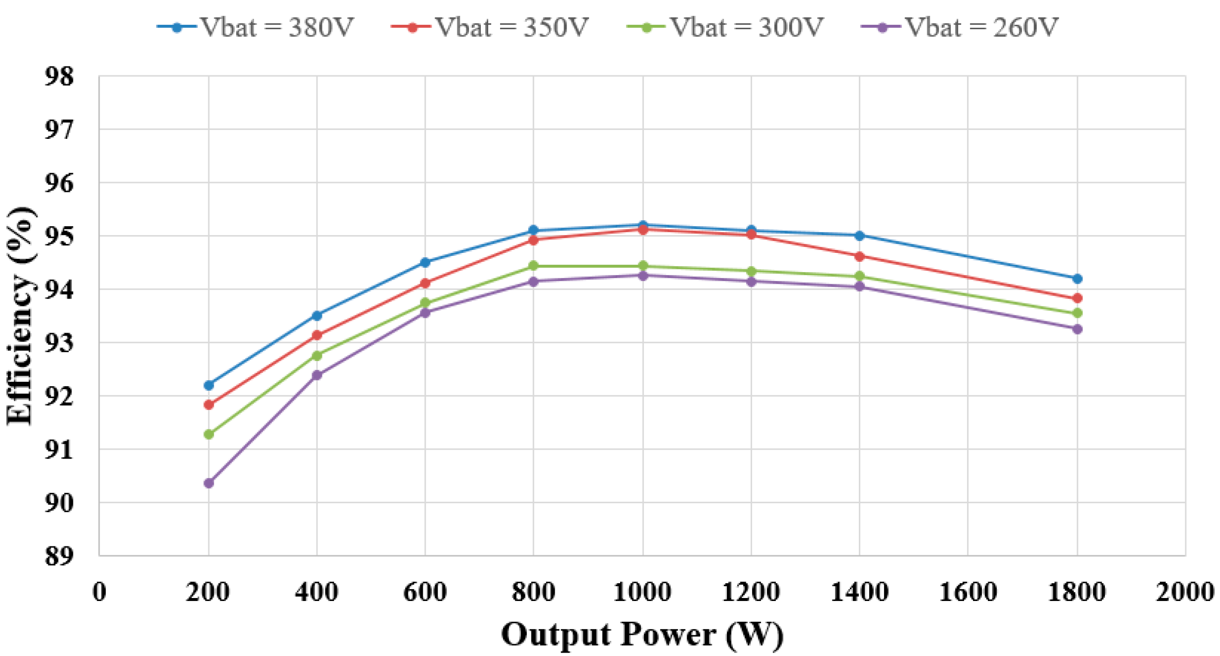
| Proposed | 14, 4, 5, 3 | 1 MHz | Equation (3) | 95.2% peak | Medium (fixed freq.) | 5.29 | 270 | ||
| [30] | 5, 2, 2, 0 | 10 kHz | Lower | 90–93% | Simplified | N/A | 100 | ||
| [31] | 4, 2, 2, 1 | 125 kHz–1 MHz | Medium | 90–93% | High (freq. modulation) | 1 | 200 | ||
| [13] | 8, 1, 2, 1 | 70–100 kHz | Limited range | 92–94% | Medium (phase shift) | N/A | 100 | ||
| [32] | 12, 3, 4, 3 | 500 kHz–1 MHz | Limited range | 93–95% | Very High (Interleaving control) | N/A | 250 |
Disclaimer/Publisher’s Note: The statements, opinions and data contained in all publications are solely those of the individual author(s) and contributor(s) and not of MDPI and/or the editor(s). MDPI and/or the editor(s) disclaim responsibility for any injury to people or property resulting from any ideas, methods, instructions or products referred to in the content. |
© 2025 by the authors. Licensee MDPI, Basel, Switzerland. This article is an open access article distributed under the terms and conditions of the Creative Commons Attribution (CC BY) license (https://creativecommons.org/licenses/by/4.0/).
Share and Cite
Manh Tuan, T.; Akram, A.S.; Choi, W. A Novel Two-Stage Power Conversion Method Suitable for 1MHz-LDC of Electric Vehicles. Electronics 2025, 14, 2403. https://doi.org/10.3390/electronics14122403
Manh Tuan T, Akram AS, Choi W. A Novel Two-Stage Power Conversion Method Suitable for 1MHz-LDC of Electric Vehicles. Electronics. 2025; 14(12):2403. https://doi.org/10.3390/electronics14122403
Chicago/Turabian StyleManh Tuan, Tran, Abdul Shakoor Akram, and Woojin Choi. 2025. "A Novel Two-Stage Power Conversion Method Suitable for 1MHz-LDC of Electric Vehicles" Electronics 14, no. 12: 2403. https://doi.org/10.3390/electronics14122403
APA StyleManh Tuan, T., Akram, A. S., & Choi, W. (2025). A Novel Two-Stage Power Conversion Method Suitable for 1MHz-LDC of Electric Vehicles. Electronics, 14(12), 2403. https://doi.org/10.3390/electronics14122403


