1. Introduction
Regenerative braking systems for brushless DC (BLDC) machines are a popular topic in scientific articles. Currently, such systems are widely used in electric vehicles (EVs) [
1,
2] and hybrid electric vehicles (HEVs) [
3,
4,
5]. Regenerative braking extends the range of an EV on a single battery charge and, in the case of HEVs, reduces fuel consumption. In addition, effective regenerative braking reduces wear on the mechanical brakes. Over time, numerous algorithms have been introduced to control the regenerative braking process of BLDC machines. These include methods that require identification of the machine shaft position (using Hall sensors) and sensorless methods.
Modulation methods using Hall sensors are most commonly used for the regenerative braking of BLDC machines due to the ease of implementing a control system that processes information from the Hall sensors, enabling the identification of the rotor shaft position with an accuracy of 60°. The algorithm using a single-switched transistor is the most commonly described in the literature [
6,
7]. This is due to the possibility of using a simplified converter structure with three transistors, which can be on either side (high or low) of the converter. An analogous modulation concept exists in the case of the method with six-switched transistors [
8]—the same fragments of instantaneous phase voltages are selected in the energy storage state. The difference with the single-switched modulation method is that all six transistors of the converter are controlled. This ensures full load symmetry of the individual transistors, reducing power losses in the converter and thus increasing the amount of power returned to the battery. The modulation method using one-branch switched transistors differs from other methods in that it allows the use of a low-cost converter consisting of one transistor branch and two diode branches [
9]. An increase in the machine phase current occurs under the influence of the sum of a phase voltage occurring in the branch with the transistors and one of the voltages occurring in the other two phases. This causes an asymmetry in the machine phase currents and the load on the individual power switches, resulting in lower power transferred to the battery compared to other modulation methods. Another disadvantage of the one-branch modulation strategy is the considerable complication of the control system due to the difficulty in identifying the machine’s shaft position, which is not directly determined by Hall sensors. In the available literature, sensorless methods are also described. The most common is the electromotive force (EMF) control method with zero crossing detection, which uses the EMF voltage in the non-powered phase during block commutation [
10,
11]. Others include the observer control method, which uses the machine current value [
12], and the magnetic anisotropy control method, which estimates the machine inductance [
13] to determine the machine shaft position.
The second group of modulation strategies that enable regenerative braking of BLDC machines includes methods that do not require the identification of the machine’s shaft position. These include the three-switched transistor modulation method [
14,
15], in which the three phases of the machine are short-circuited simultaneously by the transistors on either the high or low side of the converter. An alternative to the three-switched transistor method is a one-branch modulation method with no rotor position detection [
16]. In this case, sensorless operation of the converter is possible for pulse width modulation (PWM) duty cycle factors in the range of 0 ÷ 50%. The algorithm partially uses the reverse conduction of field-effect transistors, which increases the converter’s efficiency. However, the narrow range of useful PWM duty cycle factors limits its use to low-voltage systems.
The modulation method with two-switched transistors [
17,
18] (classified as a sensor method) stands out from the others because it is the only one that provides effective electric braking at vehicle speeds close to zero. This is because, in addition to the machine’s rotational voltages, the battery voltage is used to force the current that generates the braking torque in the BLDC machine. A currently well-known modulation method uses diode converter conduction in the energy recovery process for the battery. These are usually the intrinsic diodes of power transistors or additional Schottky diodes. In vehicles powered by low-voltage batteries (typically less than 50 V, such as mild hybrids and light electric vehicles), voltage drops across conducting diodes pose a major problem in achieving high converter efficiency. This paper proposes a new converter modulation strategy utilising the reverse conduction of power field-effect transistors [
19,
20], instead of diode conduction. The goal is to achieve high converter efficiency by significantly reducing conduction losses. This solution has not yet been employed in regenerative braking systems of electric vehicles. Previously known application areas include so-called synchronous rectifiers [
21] and multi-phase PWM-controlled Buck DC/DC converters [
22].
2. Methodology
First, the classical modulation method using diode conduction will be analysed. During the time intervals in which the diodes are conducting, turn-on signals for the metal–oxide–semiconductor field-effect transistors (MOSFETs) will be added (forcing reverse conduction). The regenerative braking system controlled by both the classical and new methods will be modelled using the average value method [
23,
24]. This approach will enable the derivation of mathematical equations for converter efficiency and battery charging power as functions of the machine’s rotational speed and PWM duty cycle. In addition, more accurate simulation studies will be conducted using MATLAB-Simulink 2024b software. In the final stage, the impact of the new modulation method on increasing the efficiency of the converter will be experimentally investigated. This will require the synthesis of the modulation methods into program code in C-language and the development of a converter control system using a high-speed DSP signal processor. The test stand will be equipped with a precision multi-channel power analyser, which will allow the converter efficiency to be calculated. The experimental results obtained will be compared with previously achieved simulation results. On this basis, a comparative analysis of the converter efficiency and the battery charging power values depending on the modulation method will be conducted. The proposed modulation strategy will be analysed in detail in terms of its advantages and disadvantages.
3. Modulation Strategy Description
This section presents the physical fundamentals of achieving the regenerative braking state in a BLDC machine. Additionally, the modulation strategy proposed by the author, which utilises the reverse conduction of MOSFET-type transistors, will be presented.
3.1. Principles of Regenerative Braking for a BLDC Machine
During regenerative braking of a BLDC machine operating with a three-phase full-bridge converter [
25], two distinct states occur: energy storage within the machine’s electromagnetic circuit and energy recovery back to the battery. While in the energy storage state, the current in the machine windings increases under the machine rotation voltages (as well as under the battery voltage in the case of the two-switched transistor modulation method). Two machine phases with the highest instantaneous phase-to-phase (in the following section, the acronym p-p will be used) voltage are short-circuited in a controlled way via the converter switches. Upon switch-off, the stored energy is delivered back to the battery through the diodes. These operating states are analogous to those of a Boost DC/DC converter.
To enable regenerative braking of the BLDC machine (energy flow from the machine to the battery), the p-p voltages must exceed the battery voltage. This voltage depends on the rotor’s rotational speed and the self-inducted voltages generated in the windings. Self-induction voltages arise from connecting/disconnecting corresponding phases of the machine—via the converter. This principle is used by most of the modulation strategies described in the literature. The two-switched transistor modulation method differs from others in that the battery voltage is summed with the corresponding phase voltages of the machine during the energy storage state. The increased overall voltage leads to a more rapid rise in the machine’s phase current, enabling effective battery charging at lower rotor speeds and reduced PWM duty cycle values. Reduced values of the PWM duty cycle contribute to significantly higher continuous power losses experienced in the converter. These losses are associated with the diode conduction during energy recovery in the case of the two-switched transistor modulation technique.
For six-transistor converters operating with low-voltage sources (up to about 50 V), the conduction loss component constitutes the largest part of the overall converter loss. By introducing reverse conduction of power field-effect transistors (at times when the converter diodes are conducting), the converter power losses can be significantly reduced. In this case, the voltage drop across the MOSFET channel resistance RDSon is usually several times smaller than the voltage drop across the diode. The introduction of this solution is especially beneficial in the classic two-switched transistor modulation strategy.
3.2. New Modulation Technique Using MOSFET Reverse Conduction
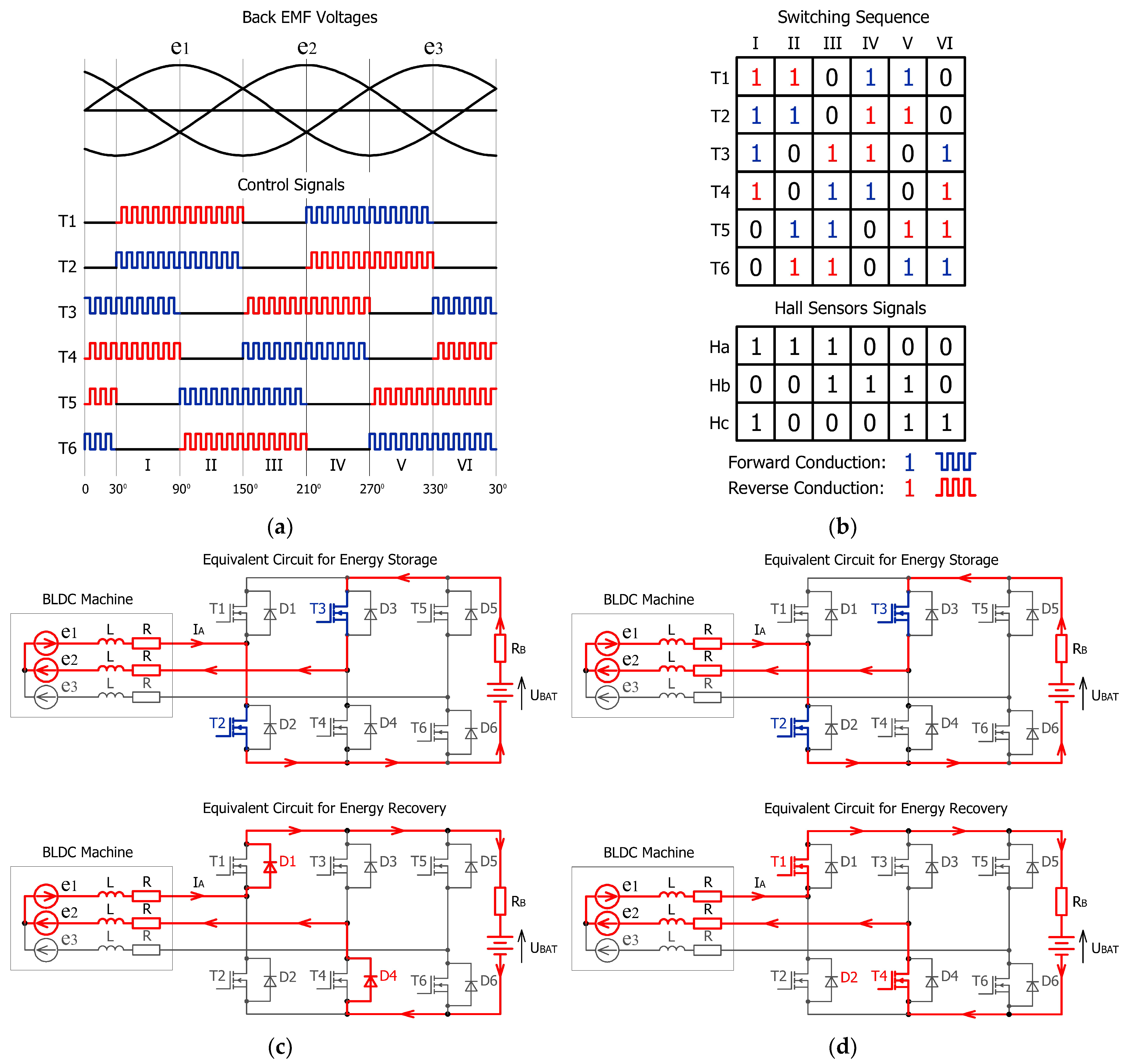
Figure 1 shows transistor switching sequences and current flow paths during energy storage/recovery for both classical and new MOSFET reverse conduction modulation methods.
The classical two-switched transistor strategy includes additional signals controlling transistors T1, T3, and T5, compared to the classical modulation method using a single-switched transistor, as shown in
Figure 1a (blue colour). These transistors are switched as follows: T1 in sectors IV and V, T3 in sectors VI and I, and T5 in sectors II and III. This results in the battery voltage being added to the phase voltages during the energy storage stage (
Figure 1c). The switching sectors are identified by three Hall sensor signals (
Figure 1b). In the first sector, an increase in the machine phase current occurs under the influence of the sum of the instantaneous phase voltages of the machine,
e1 and
e2, and the battery voltage
UBAT. The current path is completed through the activated T2 and T3 transistors. Upon turning off transistors T2 and T3, the voltages
e1 and
e2 resulting from rotation are summed with the self-induction voltages in phases
A and
B. Through the intrinsic diodes D1 and D3, the current flows towards the battery. As mentioned earlier, for the two-switched transistor modulation strategy, diode conduction occurs exclusively in the energy recovery state.
Based on the analysis of the diode’s conduction states, sectors are distinguished in which additional turn-on signals for the transistors (switching them to reverse conduction) are applied (
Figure 1b (red colour)). These transistors are turned on according to the following sector allocation: T1 in I and II, T2 in IV and V, T3 in III and IV, T4 in I and VI, T5 in V and VI, and T6 in II and III. As shown in
Figure 1d, the current previously conducted by the diodes is now handled by the reverse conduction channels of the field-effect transistors, resulting in much lower converter losses than in the classical modulation method.
It should be noted that the current path presented in
Figure 1d represents an idealised case, assuming zero transistor turn-on and turn-off times, and therefore does not account for intrinsic diode conduction during dead-time intervals.
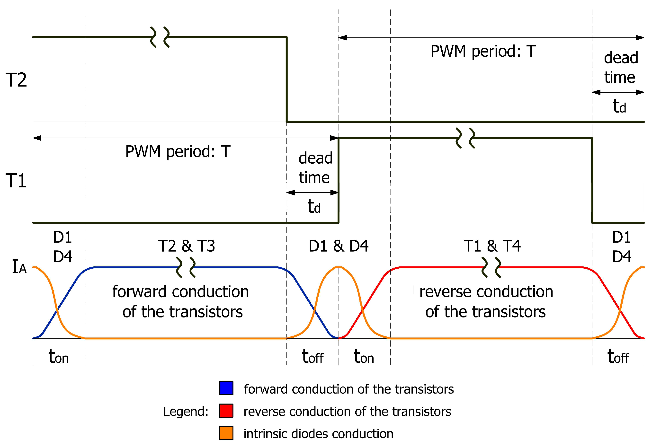
Figure 2 presents the complete commutation process of the transistor–diode switches, taking into account the conduction of intrinsic diodes that occurs due to the inclusion of transistor dead times, shown here for the first switching sector.
When transistors T2 and T3 are switched off (toff time), the energy stored in the phase inductances of the machine enforces the continued flow of current through diodes D1 and D4. The current flowing through the diodes gradually increases, while the current conducted by transistors T2 and T3 in their forward direction gradually decreases, which is related to their turn-off process. Then, during the ton time, transistors T1 and T4 are turned on for reverse conduction. They correspond to the diodes conducting in the previous phase, through which energy is returned to the battery. During their turn-on, these transistors take over the current previously conducted by the diodes, significantly reducing the associated power losses. In the remaining sectors of converter operation, there is a full analogy regarding the commutation of the transistor–diode switches. The contribution of diode conduction (and thus power losses in the diodes) during the PWM period (td/T), resulting from commutation occurring within the transistor modules, is negligible. This is due to the low switching frequencies of the transistors (typically below 20 kHz) used in standard BLDC motor drive systems.
The following section of the article presents a discussion on the efficiency of the three-phase full-bridge converter and the battery charging power. These results were derived from the mathematical model, the circuit model created in Matlab-Simulink 2024b software, and bench testing for both the classical conduction modulation method and the new modulation method based on reverse conduction of the field-effect transistors. To shorten the names of the modulation strategies, the acronyms CCMM and RCMM will be used to refer to the classical conduction modulation method and the reverse conduction modulation method, respectively.
4. Mathematical Representation of the Regenerative Braking System
The equivalent circuits of the regenerative braking system (composed of the converter switches, BLDC machine phases, and battery), controlled by both the classical and new modulation strategies, are shown in
Figure 3.
The current flow path for the CCMM is shown in
Figure 3a, while
Figure 3b shows the current flow path for the RCMM. In the mathematical model, the current through the machine’s windings is considered constant, and the machine phase voltages have a sinusoidal waveform. The converter transistors were represented as elements with linear current–voltage curves, defined by the channel resistance
RDSon in the transistor’s on-state. The intrinsic diodes present in the field-effect transistor structure were modelled as voltage drops equal to the threshold voltage of the diode
Uf. An ideal DC voltage source
UBAT connected in series with a resistor
RB simulating the battery’s internal resistance was used to model the battery. Dynamic losses during the transistor’s switching are neglected in the model. The dynamic losses account for no more than 2% of the overall power losses in the converter. This value was obtained from the losses model [
26], which takes into account all the parameters of the field-effect transistor used in the experiment (IRFP90N20D), the switched voltage/current value (24 V/5 A), and the carrier frequency of the PWM waveforms (20 kHz). By simplifying the model, it is possible to analytically determine the most important parameters of the system, such as converter efficiency and the battery charging power. Expanding the mathematical model to include additional loss components would complicate the form of the formulas.
The average machine p-p voltage is given by the following equation:
where the voltage coefficient is represented by
a,
Urms refers to the RMS phase voltage,
k is the back EMF constant, and
e1(
t) and
e2(
t) indicate the instantaneous phase voltages.
Based on the equivalent circuits shown in
Figure 3, the average voltage value across the machine’s equivalent inductance is given as follows:
For RCMM:
where
IA represents the average value of the current in the machine phase,
R is the generator phase resistance,
RB is the battery internal resistance,
RDSon represents the MOSFET transistor’s on-state drain–source resistance,
Uf is the forward voltage drop of the diode,
UBAT is the battery voltage,
akω is the average value of the p-p voltage,
D is the PWM duty cycle, and
T is the period time.
Under the assumption that the average voltage across the inductance (evaluated over the modulation period) equals zero, the corresponding average current
IA is given by
The relationship between battery charging power
PBAT and the PWM duty cycle
D can be expressed as
Over the modulation period, the overall power losses
Ploss of the converter are expressed as
Taking into account Equations (9) and (10), the converter efficiency
η can be expressed as
The equations were then entered into the Matlab-Simulink environment in block form. The block form of the equations allows for free access to all the mathematical model parameters at any stage of the calculations (including the following variables: the rotational speed of the machine represented by the akω factor, and the duty cycle factor D). The parameters of the mathematical model correspond to the real values of the components used in the experimental study.
The parameters of the mathematical model are listed in
Table 1.
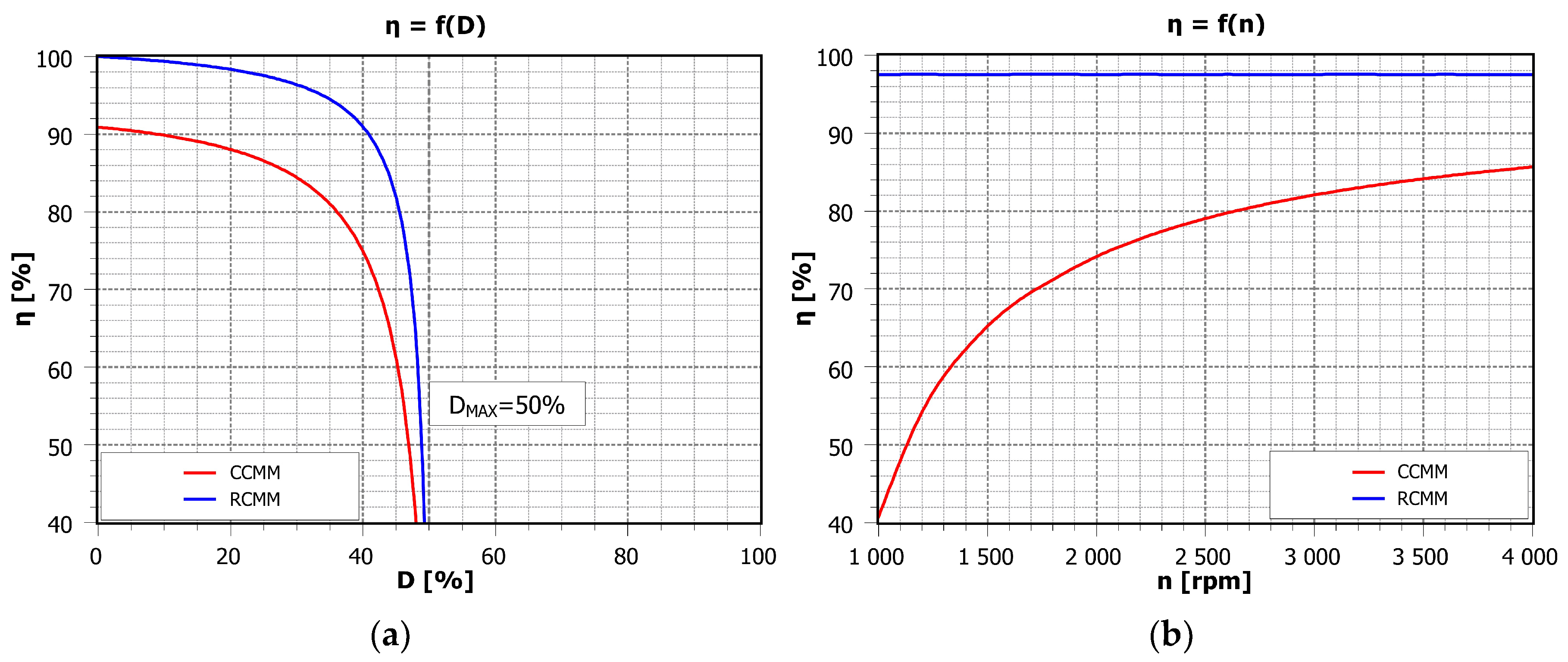
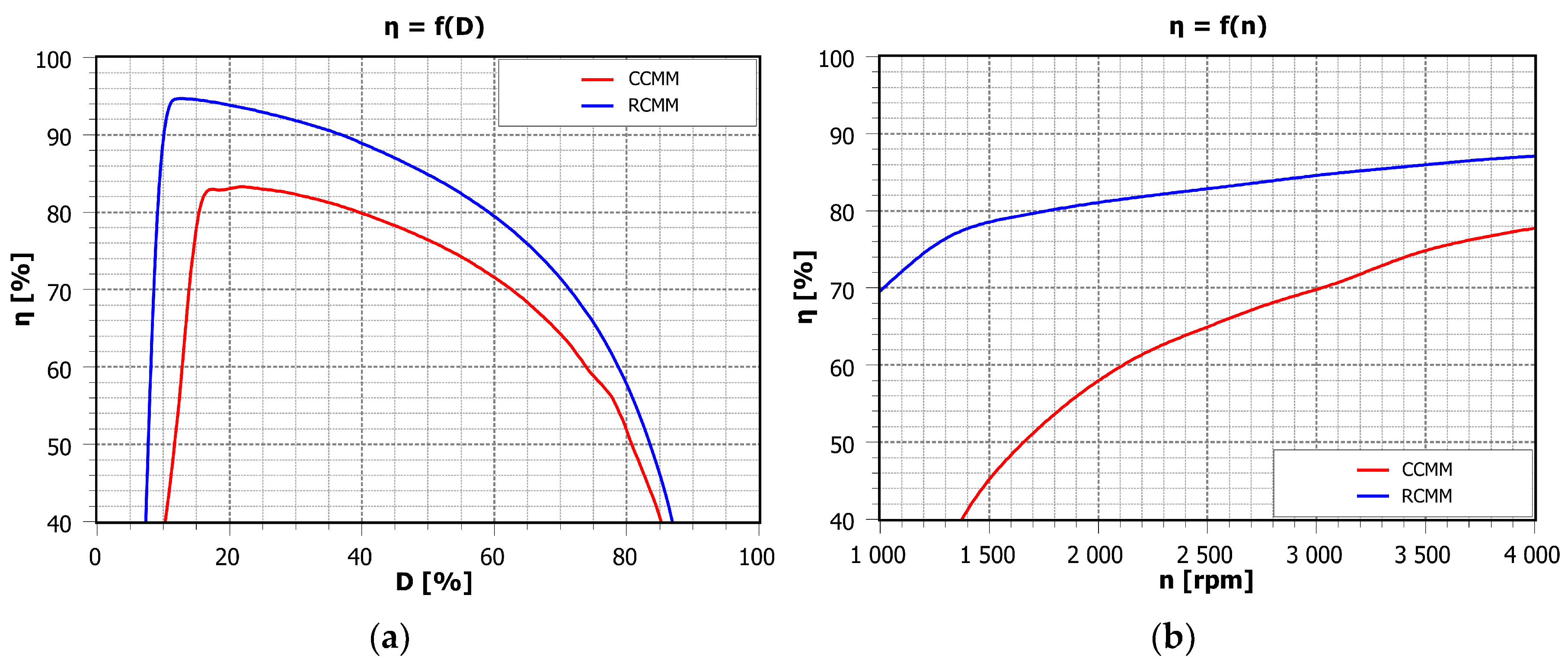
The efficiency of the converter depending on the PWM duty cycle and machine rotational speed is illustrated in
Figure 4.
For the two-switched transistor modulation strategy, the effective PWM duty cycle factor ranges from 0 to 50%. This is a characteristic feature of this modulation method, associated with a faster current rise in the machine’s windings. This is due to the additional battery voltage attached to the machine phases in the energy storage state. The use of reverse conduction in transistors leads to an approximately 9% improvement in the efficiency of the converter across a broad range of PWM duty cycle values (
Figure 4a). A significantly greater efficiency increase is observed in relation to the machine’s rotational speed (
Figure 4b). At the lowest speed of 1000 rpm, the efficiency improves by nearly 60%, while at the rated speed, the improvement reaches 12%.
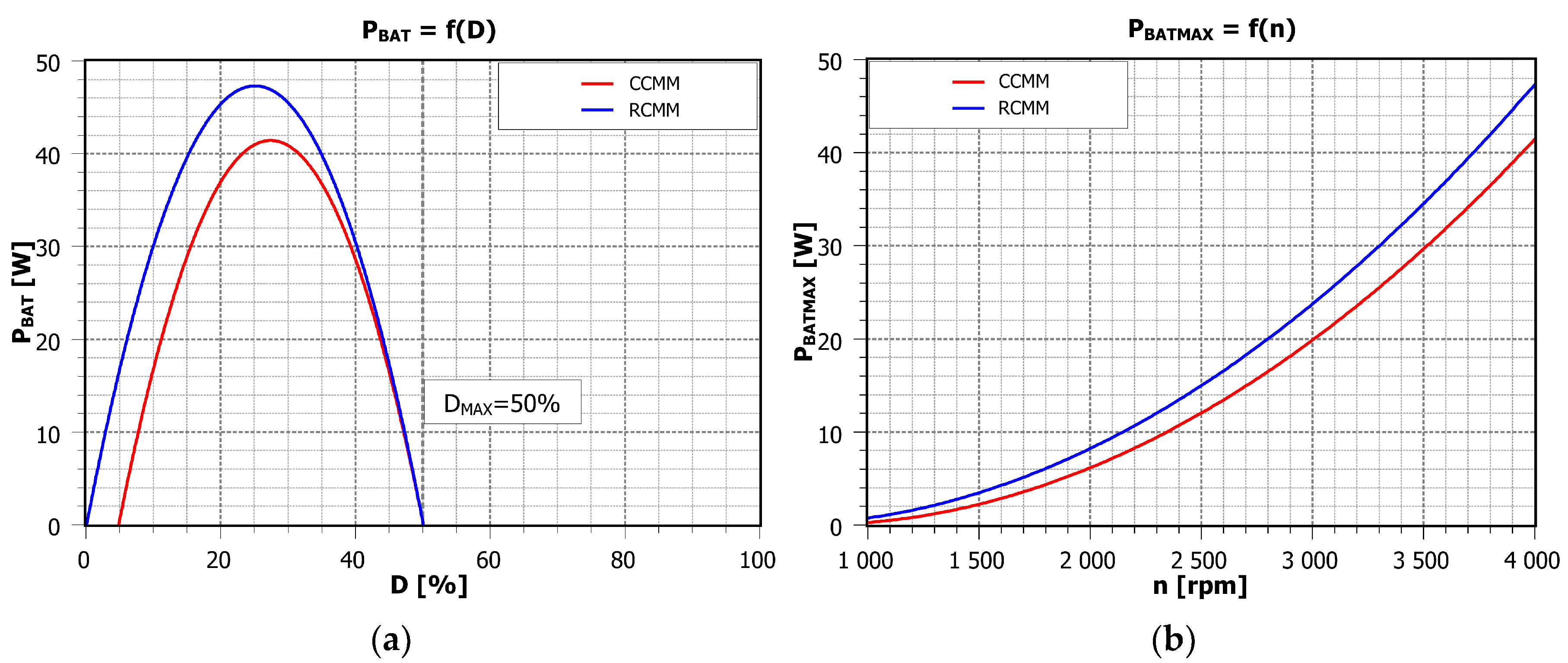
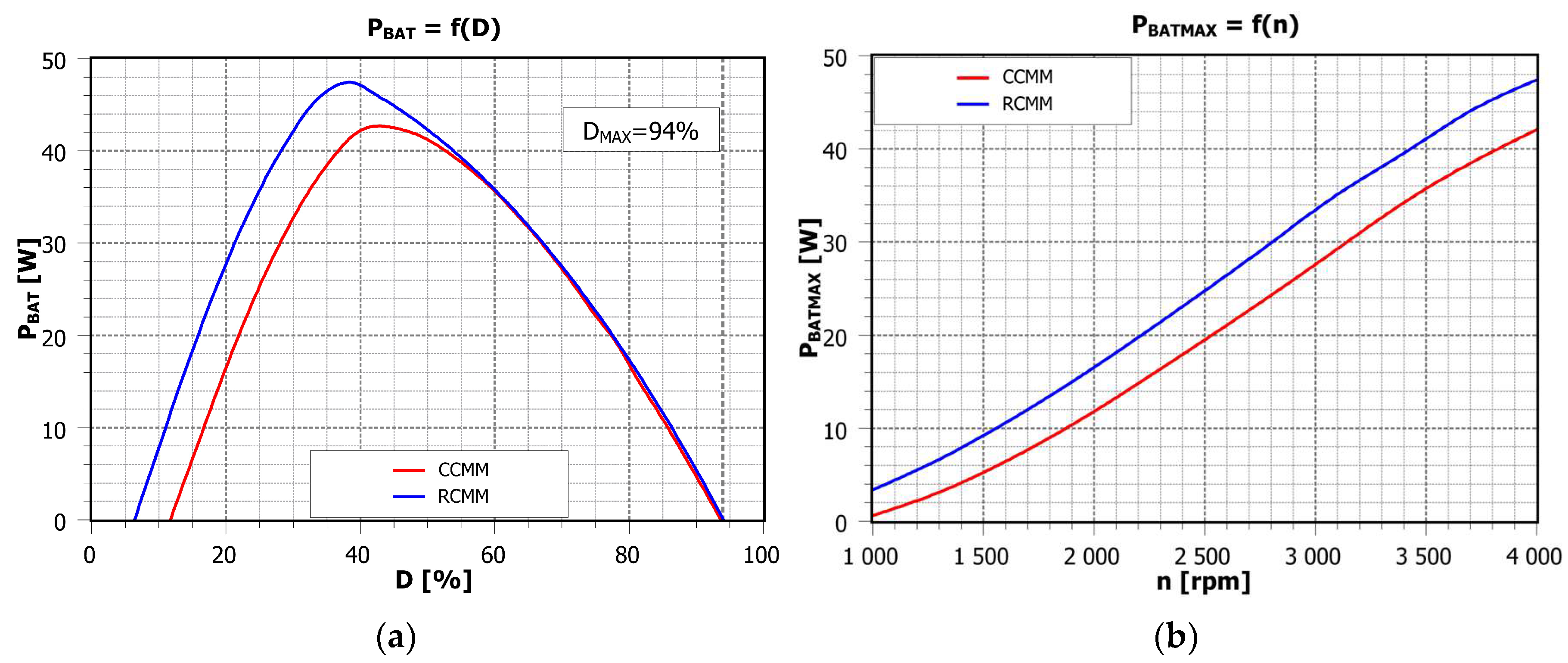
The battery charging power depending on the PWM duty cycle and the machine rotational speed is presented in
Figure 5.
Due to the enhanced efficiency of the converter resulting from the RCMM application, the battery charging power increases. At the rated speed of 4000 rpm, a maximum power of 47.3 W is obtained with a PWM duty cycle of 25%, while the CCMM yields 41.4 W at a PWM duty cycle of 27.4%, as shown in
Figure 5a. The use of reverse conduction also increases the maximum battery charging power compared to the CCMM over a wide range of machine rotational speeds (
Figure 5b).
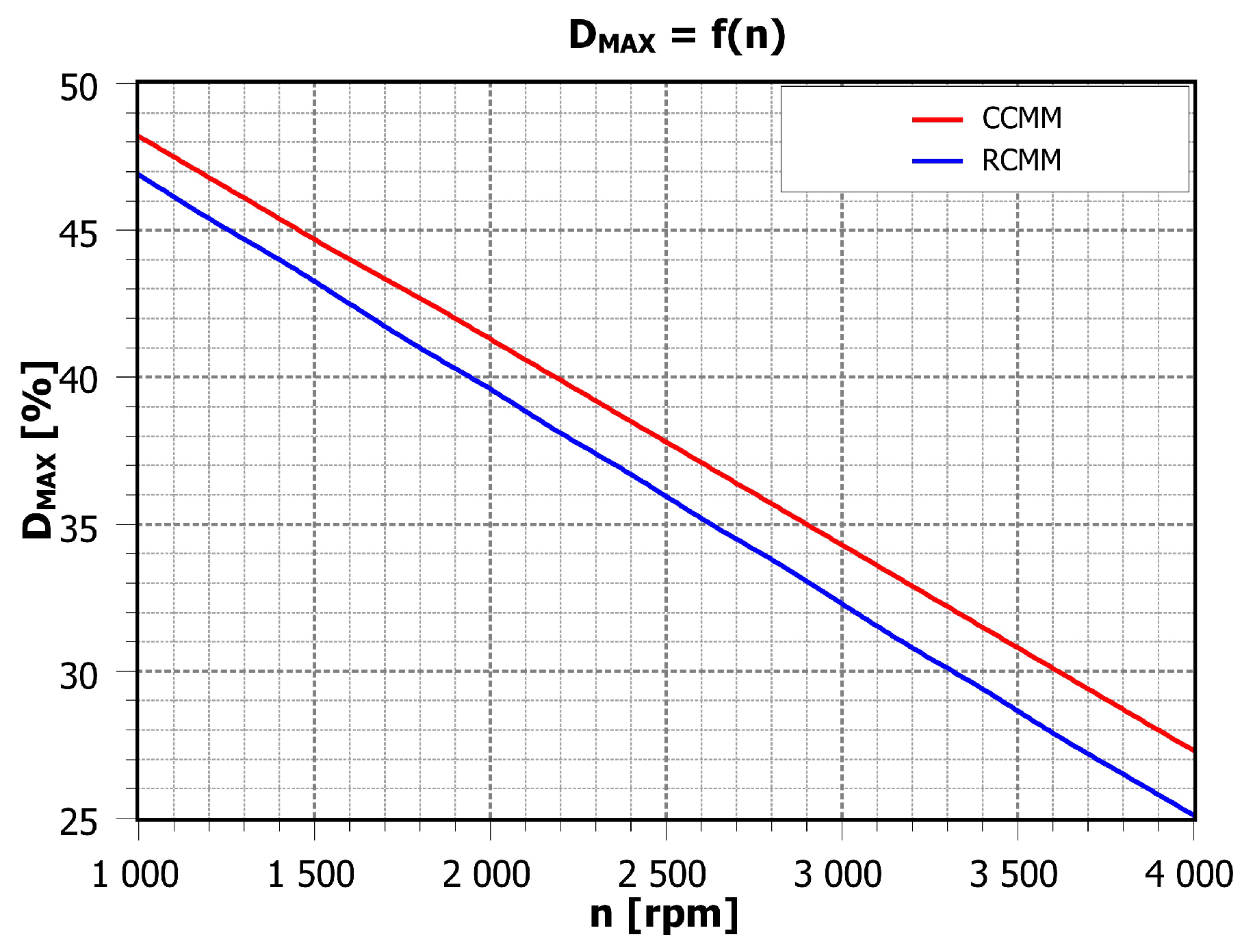
The PWM duty cycle corresponding to the maximum battery charging power as a function of the machine’s rotational speed is presented in
Figure 6.
As the rotational speed increases, the difference in the resulting maximum battery charging power values also increases, reaching a maximum of 5.9 W at the rated speed of the machine. This is due to the lower PWM duty cycle values
DMAX at higher rotational speeds, and thus significantly higher continuous converter power losses in the case of the CCMM (
Figure 6).
5. Simulation Results
In the following section, results from simulations conducted with a Matlab-Simulink circuit model are presented. This model takes into account many more parameters of the regenerative braking system components (such as the machine phase inductance
L and the PWM frequency) compared to the mathematical model presented in
Section 3. It thus allows analysis of the dynamic states occurring in the system, including voltage, current, and power waveforms.
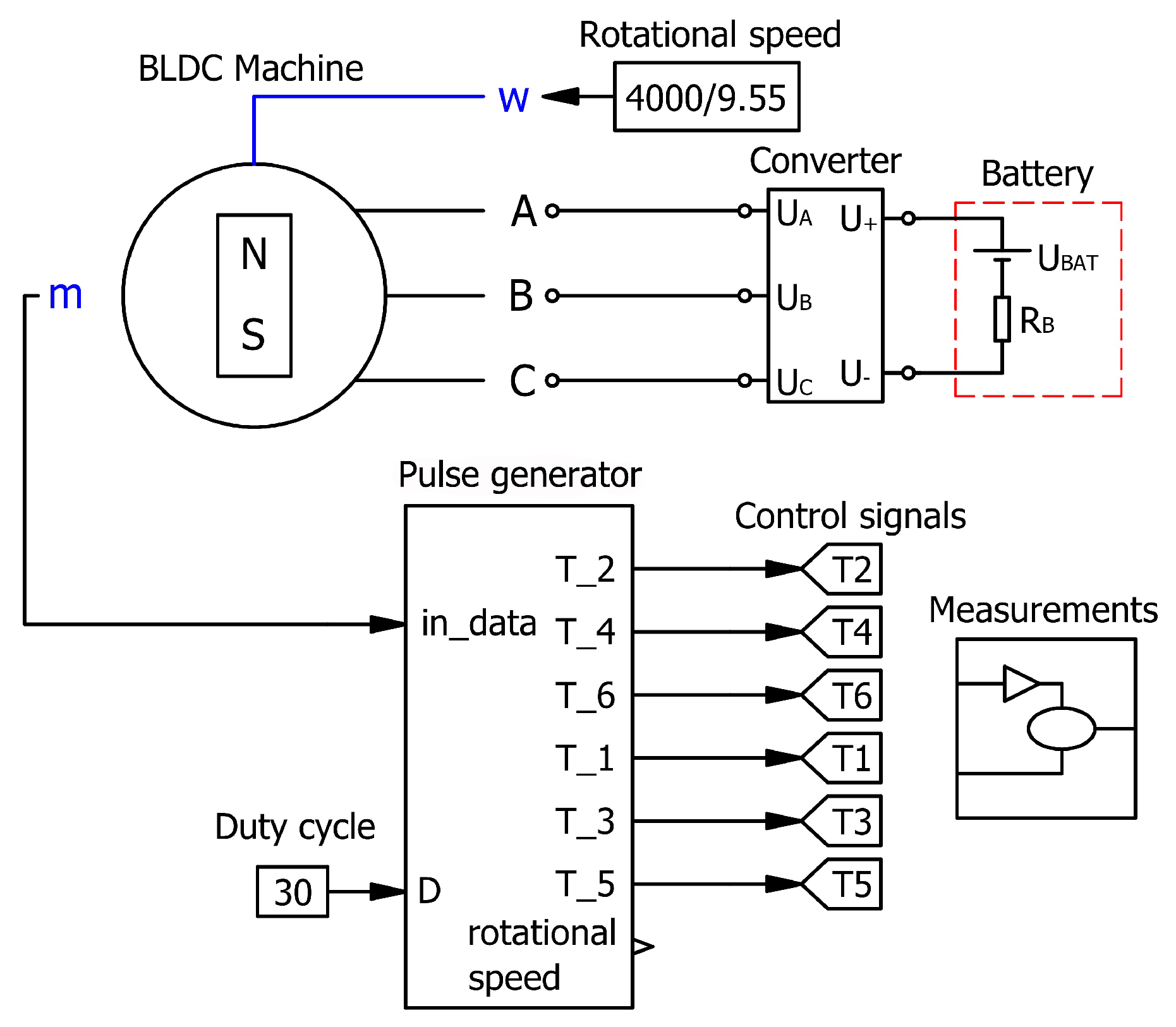
The simulation setup of the analysed regenerative braking system is shown in
Figure 7.
The simulation setup consists of the following main components: a brushless permanent magnet DC machine (BLDC) operating in generator mode, a three-phase converter (Converter), a rotational speed reference (Rotational speed), a duty cycle reference (Duty cycle), a battery bank (Battery) representing the energy storage element, a measurement module (Measurements) for measuring voltages, currents, and power in the system, and a pulse generator module (Pulse generator) responsible for generating the transistor control signals.
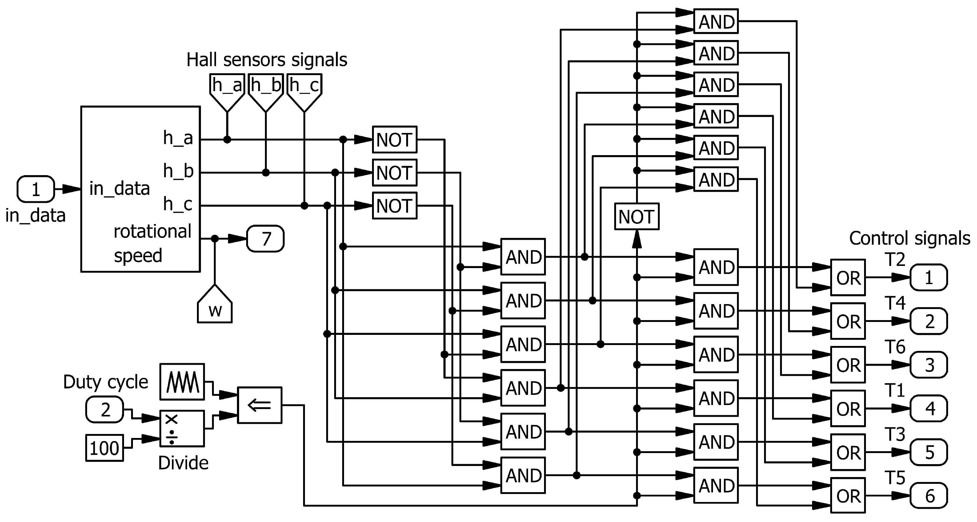
Figure 8 presents the pulse generator, which constitutes a crucial component of the simulation model.
The pulse generator is responsible for generating the switching signals for the converter transistors (Control signals) by accurately determining the rotor’s instantaneous position using the Hall sensor signals. In this model, the transistor dead time has been neglected, as it represents less than 1% of the PWM period, making its impact on its accuracy negligible (discussed in detail in
Section 7—Discussion). This setup reflects the steady-state operating conditions assumed in the research methodology for comparing the CCMM and RCMM strategies at fixed machine rotational speeds and duty cycles with respect to converter efficiency and battery charging power.
Parameters of the simulation system are listed in
Table 2.
The efficiency of the converter depending on the PWM duty cycle and machine rotational speed is presented in
Figure 9.
With RCMM, the converter efficiency improves over a wide span of PWM duty cycle values, between 7% and 94%, as illustrated in
Figure 9a. The average efficiency increase, denoted as Δ
ηAV, is expressed by the following equation:
where Δ
ηAV represents the average increase in converter efficiency,
N indicates the number of samples,
ηri refers to the converter efficiency for RCMM, and
ηki to that for CCMM.
Calculated from Equation (12), Δ
ηAV is 7.9% over this range. A significantly higher increase in converter efficiency is observed with respect to rotational speed, as shown in
Figure 9b. The average increase in converter efficiency, calculated using Equation (12), is 22.9% over a wide range of machine rotational speeds: from 1000 to 4000 rpm.
Battery charging power depending on the PWM duty cycle and the machine rotational speed is shown in
Figure 10.
The implementation of reverse conduction in the algorithm with two-switched transistors allowed for obtaining higher battery charging power for a duty cycle factor in the range of 6 ÷ 55% (
Figure 10a). The limit value of the PWM duty cycle (for both CCMM and RCMM) is
DMAX = 94%. The highest power of 47.4 W was achieved at a PWM duty cycle of 39%. Applying reverse conduction in MOSFETs enables an increase in power delivered to the battery across a broad range of machine rotational speeds, as shown in
Figure 10b.
The average value of the percentage increase in battery charging power
ΔPBMAV is given by
where Δ
PBMAV represents the percentage increase in the average value of the battery charging power,
N indicates the number of samples, and
PBM_ri and
PBM_ki refer to the battery charging powers of the RCMM and CCMM, respectively.
Calculated from Equation (13), ΔPBMAV is 22.5% over a wide range of machine rotational speeds: 1000 ÷ 4000 rpm.
6. Experimental Results
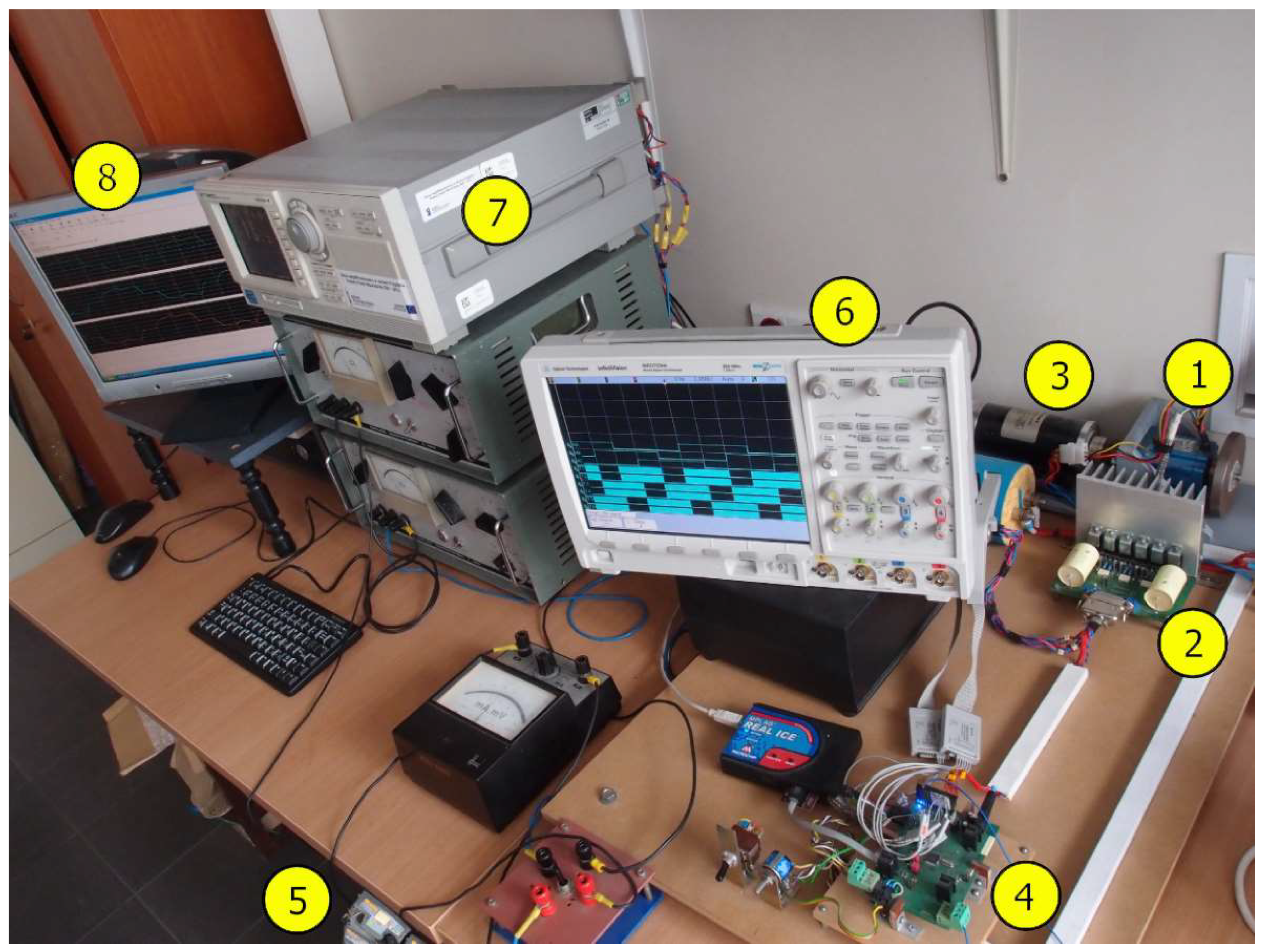
Figure 11 shows the experimental test bench used to evaluate the converter’s efficiency and the power delivered to the battery in the regenerative braking system.
The setup consists of the following components: (1) BLDC machine PBL60-78, (2) three-phase full-bridge converter built with MOSFET IRFP90N20D, (3) DC motor PRMO-65-1101C, (4) microprocessor control system based on DSPIC33FJ128MC706, (5) two series-connected CA530 lead–acid batteries, (6) Agilent MSO7034A digital oscilloscope, (7) Yokogawa WT1600 power analyser, (8) measurement computer (wired to the power analyser) for collecting and archiving the data obtained.
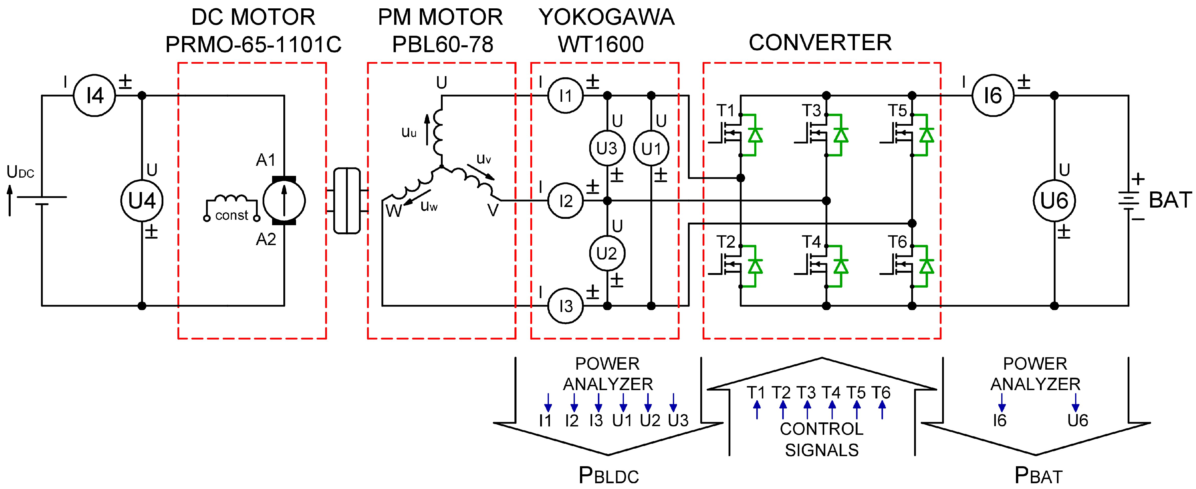
The schematic of the measurement setup is shown in
Figure 12.
The measurement system was implemented using the Yokogawa WT1600 power analyser. The power analyser captures the instantaneous voltage and current values in the examined system: p-p voltages and phase currents of the BLDC machine, battery voltage, and battery charging current. This makes it possible to determine the converter efficiency depending on the modulation method.
Example waveforms of the p-p voltages and phase currents of the machine are shown in
Figure 13. The waveforms were measured at 3000 rpm of the machine and a 37% PWM duty cycle.
The RMS values of voltages and currents and the control system parameters related to the waveforms in
Figure 13 during the machine’s regenerative braking state are listed in
Table 3.
Based on these, the BLDC machine output power PBLDC and the battery charging power PBAT are calculated, maintaining a measurement error below 0.2%.
The converter efficiency, obtained from the power measurements in the analyser, can be expressed as
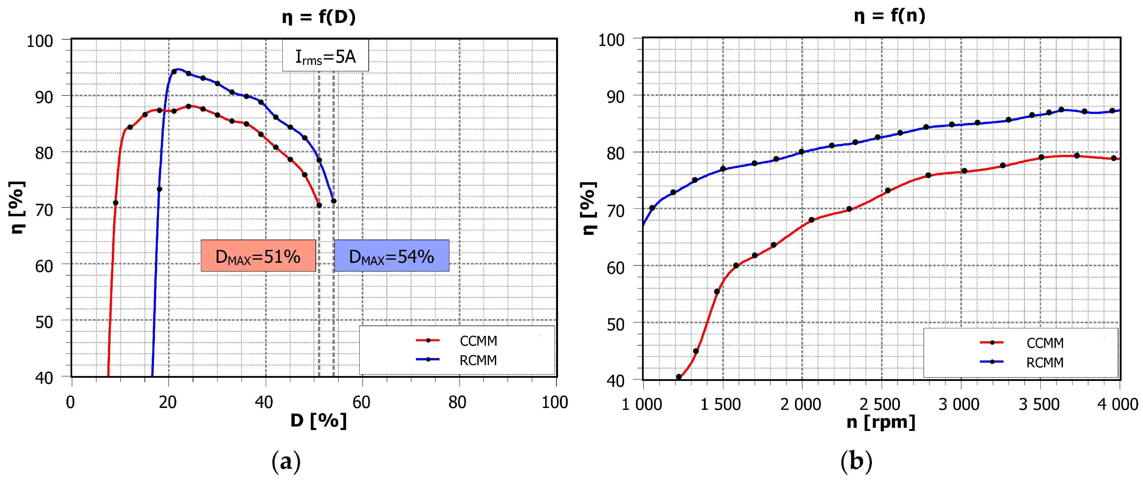
The efficiency of the converter depending on the PWM duty cycle and machine rotational speed is presented in
Figure 14.
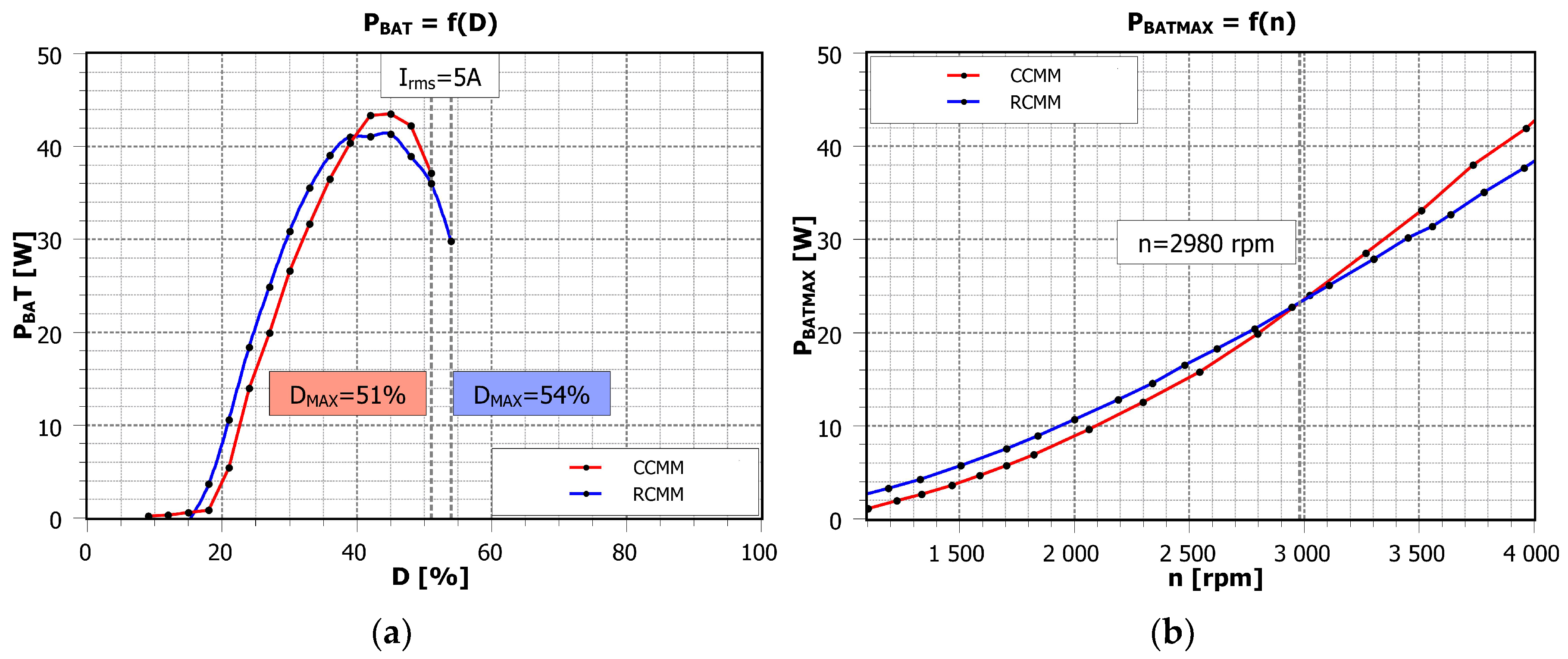
As mentioned earlier, there is a faster increase in the machine phase currents with the two-switched transistor modulation method. This is due to the summation of the battery voltage with the corresponding machine phase voltages during the energy storage stage. As a result, the effective PWM duty cycle range is limited to 51% for the CCMM and 54% for the RCMM, as shown in
Figure 14a. Beyond these values, the machine’s phase currents exceed its rated value of 5 A. For this reason, further measurements (for both the converter efficiency and the battery charging power) were not continued. For the RCMM, the converter efficiency was improved within the PWM duty cycle range of 19 to 54% (
Figure 14a). Over this interval, the average increase in converter efficiency was 5.2%. The highest efficiency value, 94.3%, was obtained for a PWM duty cycle of 21%. With the CCMM, the maximum efficiency value obtained was 88%. A much higher increase in the converter efficiency (due to the use of reverse conduction) occurs in the machine rotational speed changes (
Figure 14b). In this case, the average value of the increase in converter efficiency was 15.2% over a wide range of machine rotational speeds: 1000 ÷ 4000 rpm.
Battery charging power depending on the PWM duty cycle and the machine rotational speed is presented in
Figure 15.
Lower conduction losses in the converter (for the RCMM) result in an increase in the battery charging power for PWM duty cycles from 19 to 39% (
Figure 15a). The relationship between the maximum battery charging power and the rotational speed of the machine is presented in
Figure 15b. For low values of the machine rotational speed, ranging from 1000 ÷ 2980 rpm, the introduction of reverse conduction increases the power returned to the battery. Above the machine rotational speed of 2980 rpm, the phenomenon of magnetic saturation intensifies. This causes a decrease in the power returned to the battery compared to the CCMM.
7. Discussion
This article compares converter efficiency and battery charging power for a six-switch bridge converter operating with a brushless DC machine in regenerative braking mode under two modulation strategies: the classical two-switched transistor modulation method (CCMM) and new method utilising reverse conduction of power MOSFETs (RCMM). To compare these, a mathematical model (
Section 4) and a simulation model in Matlab-Simulink software (
Section 5) were developed. In the final part, measurements from the test bench were presented (
Section 6) to validate the results obtained through theoretical analysis.
The following section discusses the differences in battery charging power and converter efficiency achieved with the new algorithm (RCMM), in relation to the applied research methods. Similar discrepancies are observed in the case of the classical modulation method (CCMM). These differences mainly result from the simplifications in the theoretical models (the average value model and the circuit model) and have not been previously commented on in the article.
In the average value model, these simplifications include the assumption of a constant current value flowing through the BLDC machine windings and a simplified model of the diode and transistor. The applied transistor model considers only static losses related to current conduction through the transistor channel in its on-state while neglecting dynamic losses occurring during switching. The power losses in the switching transistor (dynamic losses) result from an intermediate state in which the voltage across the transistor decreases while the current increases (during turn-on) or vice versa (during turn-off). The switching time of a transistor depends on various parameters, the most significant of which are the gate–drain and source–drain junction capacitances, which need to be recharged, as well as the magnitude of the switched voltage and current. An additional factor affecting dynamic losses is the transistor switching frequency. In the analysed system, dynamic losses represent only a few percent of the total losses occurring in the converter. The average value model also does not consider undesirable commutation phenomena, such as the uncontrolled takeover of current conduction by intrinsic diodes during the energy recovery stage. Neglecting these phenomena leads to the disappearance of the power delivered to the battery (
Figure 5a) and the converter efficiency (
Figure 4a) at a PWM duty cycle
D of 50%, which is not observed in the circuit model or experimental studies. The 50% duty cycle value is a consequence of the faster increase in the machine winding current caused by the battery voltage being added to the machine phase voltages during the energy storage state. This effect occurs in both the classical modulation method (CCMM) and the new reverse conduction-based method (RCMM).
The circuit model takes into account parameters from the experimental setup, such as the machine’s phase inductance and the current–voltage characteristics of transistors and diodes, which are close to those of real components. Differential equations are further employed to characterise the BLDC machine’s operating states in generator mode. This leads to a close match between the predicted and experimentally obtained battery charging power (
Figure 10a) and converter efficiency (
Figure 9a) at higher PWM duty cycle values. Another factor contributing to the discrepancies between theoretical and experimental results is the time-varying battery voltage. In real experimental conditions, this voltage was not constant (24 V was assumed in the theoretical considerations) but increased due to the charging process, leading to an underestimation of the power delivered to the battery.
Neither the average value model nor the circuit model accounted for the phenomenon of diode conduction during transistor dead-time intervals. This simplification was made due to the marginal contribution of this effect at the switching frequency used. In the analysed system, a PWM frequency of 20 kHz was selected, which is a typical value for industrial motor drive applications. At this frequency, the proportion of dead time in the switching period is marginal, and the associated conduction losses in intrinsic diodes are negligible. However, at higher switching frequencies (not commonly used in standard drive systems), the effect becomes significant. Increased conduction time of the diodes can lead to significant additional losses, thereby reducing converter efficiency. In such cases, transistors based on modern semiconductors, such as SiC [
27,
28] or GaN [
29,
30], are recommended. These devices enable shorter dead times and lower channel resistance, which further reduces conduction losses.
For better accuracy of the average value model compared to the experimental results, it is necessary to account for the variation in current in the windings of the BLDC machine and employ a more precise diode and transistor model that includes both static and dynamic losses. As the transistor switching frequency increases, the share of dynamic losses in the total converter losses also grows, making this an important direction for further research—especially in the context of the latest silicon carbide (SiC) and gallium nitride (GaN) power transistors, which feature significantly shorter turn-on and turn-off times. A further improvement in the accuracy of the average value model can be achieved by including commutation phenomena, which have not yet been analysed in the available scientific literature.
These findings confirm that the applied modelling simplifications are appropriate for standard industrial conditions and do not compromise the validity of the conclusions. At the same time, they highlight potential areas for further refinement in applications requiring higher switching frequencies or more precise prediction of converter efficiency and battery charging power.
8. Conclusions
Although the developed algorithm refers to the well-known concept of synchronous rectification, commonly used in high-efficiency voltage rectifiers, its application in regenerative braking of BLDC machines has not yet been the subject of any scientific publication. Therefore, the presented solution represents an original contribution to the field, particularly in the context of low-voltage systems.
An additional advantage of the proposed modulation method is its ease of implementation. It requires no changes to the converter topology typical for drive systems (standard three-phase transistor bridge), nor any modifications to the hardware platform. The algorithm can be executed on standard DSP processors commonly used in industrial motor drives, ensuring compatibility with existing systems.
Simulation and experimental results have confirmed that RCMM significantly improves converter efficiency compared to CCMM. In particular, at low rotational speeds of the machine, the new modulation strategy improves the efficiency of the converter by approximately 30%. Experimental tests conducted over a wide range of machine rotation speeds (1000 ÷ 4000 rpm) showed an average increase in converter efficiency of 15.2%. The maximum converter efficiency for the RCMM reaches 94.3%, surpassing CCMM’s performance, which peaks at 88%. Additionally, the maximum power returned to the battery is also higher with the RCMM than with CCMM. Importantly, these improvements are achieved without requiring high-performance microcontrollers, meaning the new method offers substantial benefits at no additional hardware cost.
According to the author, the use of advanced modulation strategies based on reverse conduction in SiC and GaN transistors can lead to a significant reduction in energy conversion losses in the converter. This aspect is especially critical in electric vehicle regenerative braking systems, as it contributes to increasing the driving range. It is also important in small-scale wind power plants and highlights the scalability and cost-effectiveness of the proposed RCMM algorithm as a means of improving energy efficiency in modern power electronic drive systems.


