Losses and Efficiency Evaluation of the Shunt Active Filter for Renewable Energy Generation
Abstract
1. Introduction
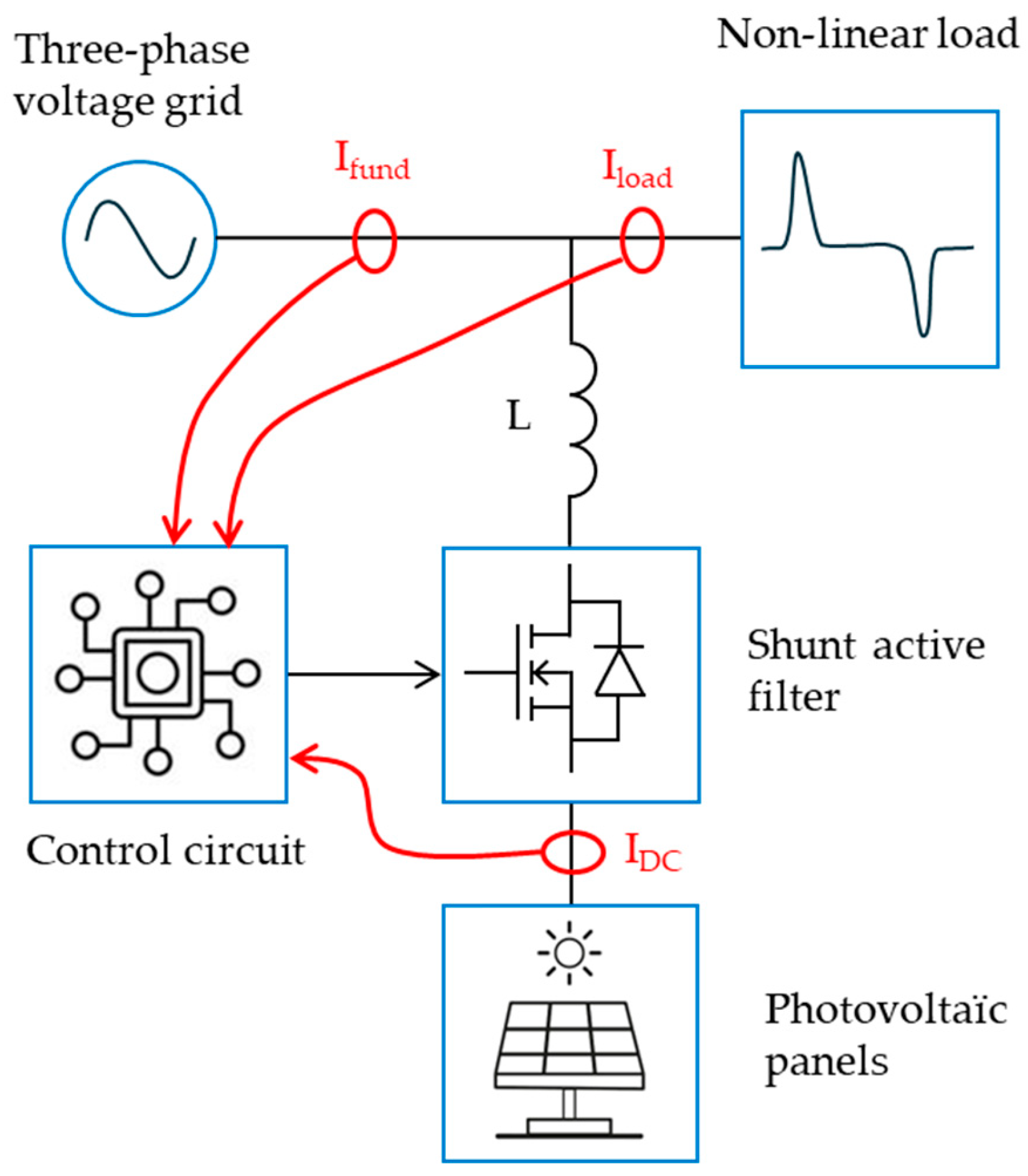
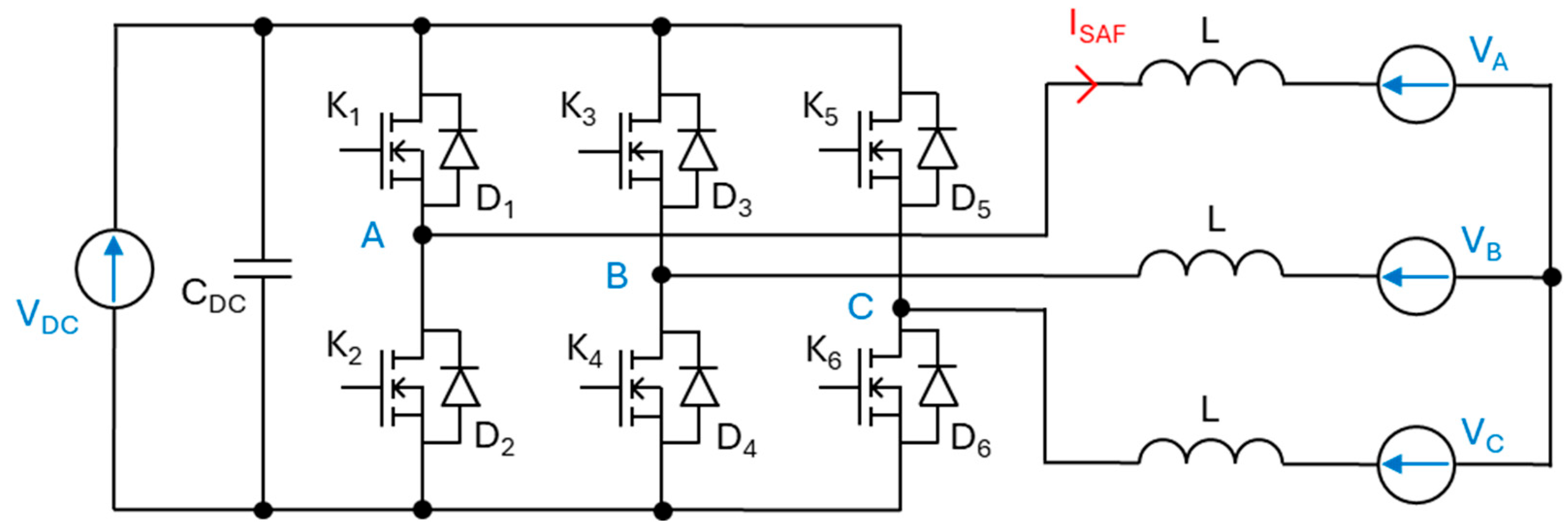
2. Electrical Structure Specifications
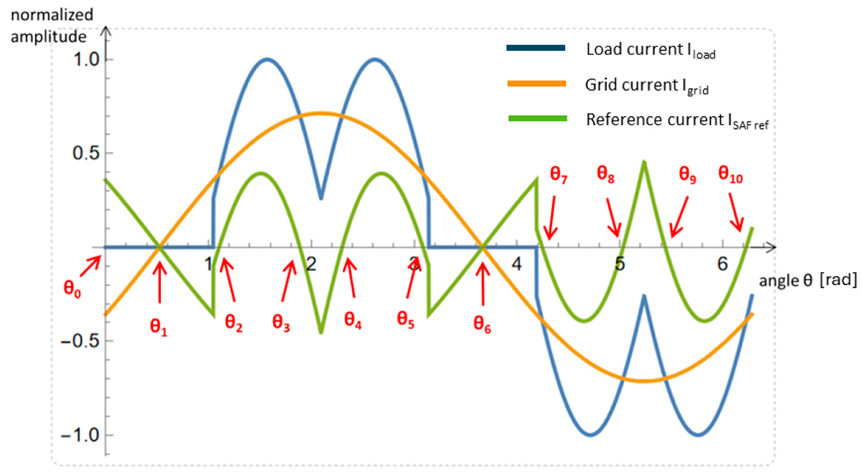
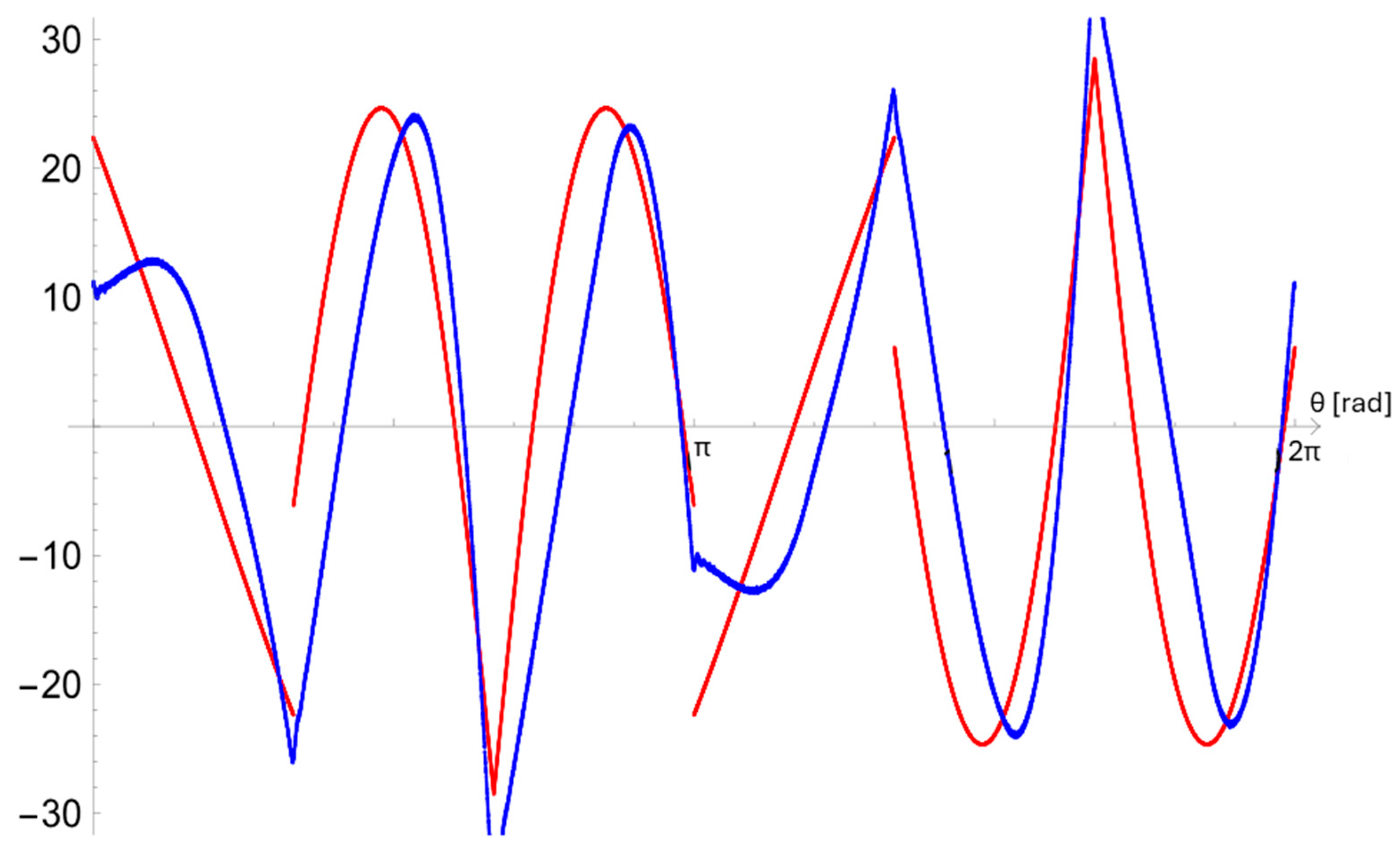
3. Current Waveforms
4. SAF Loss Computation
4.1. VSI Loss Computation in the SAF-Only Condition
4.2. VSI Loss Computation in the SAF-REG Condition
4.3. Design Considerations
5. Efficiency Comparison Between IGBT and SiC MOSFET
6. Efficiency Comparison for Different DC Voltages
- Vdc = 800 V, with MOSFET SiC 1200 V rating (reference case);
- Vdc = 1000 V, with MOSFET SiC 1700 V rating;
- Vdc = 1200 V, with MOSFET SiC 1700 V rating.
7. Conclusions
Author Contributions
Funding
Data Availability Statement
Conflicts of Interest
References
- Fujita, H.; Akagi, H. The unified power quality conditioner: The integration of series- and shunt-active filters. IEEE Trans. Power Electron. 1998, 13, 315–322. [Google Scholar] [CrossRef]
- Schaffner. “ECOsine® Active Harmonics Compensation in Real-Time”. August 2015. Available online: https://www.schaffner.com/fileadmin/user_upload/Media/Downloads/installation-manual-operating-instructions-ecosine-activ-REV6.pdf (accessed on 1 April 2025).
- Tareen, W.U.; Mekhilef, S.; Seyedmahmoudian, M.; Horan, B. Active power filter (APF) for mitigation of power quality issues in grid integration of wind and photovoltaic energy conversion system. Renew. Sustain. Energy Rev. 2017, 70, 635–655. [Google Scholar] [CrossRef]
- Gomes, C.C.; Cupertino, A.F.; Pereira, H.A. Damping techniques for grid-connected voltage source converters based on LCL filter: An overview. Renew. Sustain. Energy Rev. 2018, 81, 116–135. [Google Scholar] [CrossRef]
- Alali, M.A.E.; Shtessel, Y.B.; Barbot, J.-P. Grid-Connected Shunt Active LCL Control via Continuous Sliding Modes. IEEEASME Trans. Mechatron. 2019, 24, 729–740. [Google Scholar] [CrossRef]
- Jayasankar, V.N.; Vinatha, U. Advanced Control Approach for Shunt Active Power Filter Interfacing Wind- Solar Hybrid Renewable System to Distribution Grid. EBSCOhost 2018, 14, 88. Available online: https://openurl.ebsco.com/contentitem/gcd:129864541?sid=ebsco:plink:crawler&id=ebsco:gcd:129864541 (accessed on 1 April 2025).
- Reznik, A.; Simões, M.G.; Al-Durra, A.; Muyeen, S.M. LCL Filter Design and Performance Analysis for Grid-Interconnected Systems. IEEE Trans. Ind. Appl. 2014, 50, 1225–1232. [Google Scholar] [CrossRef]
- Imam, A.A.; Sreerama Kumar, R.; Al-Turki, Y.A. Modeling and Simulation of a PI Controlled Shunt Active Power Filter for Power Quality Enhancement Based on P-Q Theory. Electronics 2020, 9, 637. [Google Scholar] [CrossRef]
- Raman, R.; Sadhu, P.K.; Kumar, R.; Rangarajan, S.S.; Subramaniam, U.; Collins, E.R.; Senjyu, T. Feasible Evaluation and Implementation of Shunt Active Filter for Harmonic Mitigation in Induction Heating System. Electronics 2022, 11, 3464. [Google Scholar] [CrossRef]
- Hoon, Y.; Mohd Radzi, M.A.; Mohd Zainuri, M.A.A.; Zawawi, M.A.M. Shunt Active Power Filter: A Review on Phase Synchronization Control Techniques. Electronics 2019, 8, 791. [Google Scholar] [CrossRef]
- Alali, M.A.E.; Sabiri, Z.; Shtessel, Y.B.; Barbot, J.-P. Study of a common control strategy for grid-connected shunt active photovoltaic filter without DC/DC converter. Sustain. Energy Technol. Assess. 2021, 45, 101149. [Google Scholar] [CrossRef]
- Acquaviva, A.; Rodionov, A.; Kersten, A.; Thiringer, T.; Liu, Y. Analytical Conduction Loss Calculation of a MOSFET Three-Phase Inverter Accounting for the Reverse Conduction and the Blanking Time. IEEE Trans. Ind. Electron. 2021, 68, 6682–6691. [Google Scholar] [CrossRef]
- Madhusoodhanan, S.; Mainali, K.; Tripathi, A.K.; Kadavelugu, A.; Patel, D.; Bhattacharya, S. Power Loss Analysis of Medium-Voltage Three-Phase Converters Using 15-kV/40-A SiC N-IGBT. IEEE J. Emerg. Sel. Top. Power Electron. 2016, 4, 902–917. [Google Scholar] [CrossRef]
- Costa, P.; Pinto, S.; Silva, J.F. A Novel Analytical Formulation of SiC-MOSFET Losses to Size High-Efficiency Three-Phase Inverters. Energies 2023, 16, 818. [Google Scholar] [CrossRef]
- Wong, M.-C.; Pang, Y.; Xiang, Z.; Wang, L.; Lam, C.-S. Assessment of Active and Hybrid Power Filters Under Space Vector Modulation. IEEE Trans. Power Electron. 2021, 36, 2947–2963. [Google Scholar] [CrossRef]
- Wang, L.; Lam, C.-S.; Wong, M.-C. The Analysis of DC-link Voltage, Compensation Range, Cost, Reliability and Power Loss for Shunt (Hybrid) Active Power Filters. In Proceedings of the 2018 IEEE PES Asia-Pacific Power and Energy Engineering Conference (APPEEC), Sabah, Malaysia, 7–10 October 2018; pp. 640–645. [Google Scholar]
- Muñoz, J.; Baier, C.; Espinoza, J.; Rivera, M.; Guzmán, J.; Rohten, J. Switching losses analysis of an asymmetric multilevel Shunt Active Power Filter. In Proceedings of the IECON 2013—39th Annual Conference of the IEEE Industrial Electronics Society, Vienna, Austria, 10–13 November 2013; pp. 8534–8539. [Google Scholar]
- Wolfspeed. “C3M0021120K Datasheet”. Available online: https://assets.wolfspeed.com/uploads/2024/01/Wolfspeed_C3M0021120K_data_sheet.pdf (accessed on 1 April 2025).
- Infineon. “IKQ50N120CH3-DataSheet”. Available online: https://www.infineon.com/dgdl/Infineon-IKQ50N120CH3-DataSheet-v02_04-EN.pdf?fileId=5546d4625bd71aa0015bd817b0150536 (accessed on 1 April 2025).
- Nitzsche, M.; Cheshire, C.; Fischer, M.; Ruthardt, J.; Roth-Stielow, J. Comprehensive Comparison of a SiC MOSFET and Si IGBT Based Inverter. In Proceedings of the PCIM Europe 2019; International Exhibition and Conference for Power Electronics, Intelligent Motion, Renewable Energy and Energy Management, Nuremberg, Germany, 7–9 May 2019; pp. 1–7. Available online: https://ieeexplore.ieee.org/abstract/document/8767737 (accessed on 1 April 2025).
- Loncarski, J.; Giuseppe Monopoli, V.; Leuzzi, R.; Zanchetta, P.; Cupertino, F. Efficiency, Cost and Volume Comparison of Si-IGBT Based T-NPC and 2-Level SiC-MOSFET Based Topology with dv/dt Filter for High Speed Drives. In Proceedings of the 2020 IEEE Energy Conversion Congress and Exposition (ECCE), Detroit, MI, USA, 11–15 October 2020; pp. 3718–3724. [Google Scholar]
- Sivkov, O.; Novak, M.; Novak, J. Comparison between Si IGBT and SiC MOSFET Inverters for AC Motor Drive. In Proceedings of the 2018 18th International Conference on Mechatronics—Mechatronika (ME), Brno, Czech Republic, 5–7 December 2018; pp. 1–5. Available online: https://ieeexplore.ieee.org/abstract/document/8624759 (accessed on 1 April 2025).


| Symbol | Parameter | Unit | Value |
|---|---|---|---|
| Vdc | DC voltage | V | 800 |
| Vs | RMS phase-to-neutral PCC voltage | V | 230 |
| Vfund | Fundamental/grid frequency | Hz | 50 |
| Vsw | Switching frequency | kHz | 16 and 100 |
| Iload | RMS current in the non-linear load | A | 61 |
| ISAF | RMS current in the SAF | A | 72 |
| Igrid | RMS current from or to the grid | A | +61 without power injection −11 with power injection |
| Parameter | Model | Simulation | Error [%] |
|---|---|---|---|
| SAF current | 15.8 A | 15.9 A | 0.3 |
| RMS current in transistor + diode | 11.1 A | 11.1 A | 0.1 |
| RMS current in transistor | 8.38 A | 8.27 A | 1.3 |
| Average current in transistor | 3.59 A | 3.81 A | 5.8 |
| RMS current in diode | 7.32 A | 7.48 A | 2.1 |
| Average current in diode | 2.35 A | 3.00 A | 22 |
| Diode conduction losses | 3.22 W | 3.61 W | 11 |
| Diode recovery losses | neglected | neglected | - |
| MOSFET solution at 100 kHz | |||
| MOSFET conduction losses | 2.11 W | 2.22 W | 5.0 |
| MOSFET switching losses | 21.0 W | 19.8 W | 6.0 |
| MOSFET total losses | 23.1 W | 22.0 W | 5.0 |
| Converter losses | 158 W | 154 W | 2.5 |
| MOSFET solution at 16 kHz | |||
| MOSFET conduction losses | 1.53 W | 1.60 W | 5.0 |
| MOSFET switching losses | 3.43 W | 3.59 W | 4.5 |
| MOSFET total losses | 4.96 W | 5.19 W | 4.4 |
| Converter losses | 48.2 W | 51.8 W | 6.9 |
| IGBT solution at 16 kHz | |||
| IGBT conduction losses | 5.10 W | 4.51 W | 13 |
| IGBT switching losses | 26.3 W | 25.2 W | 4.3 |
| IGBT total losses | 31.4 W | 29.7 W | 5.7 |
| Converter losses | 207 W | 200 W | 3.5 |
| Parameter | Model | Simulation | Error [%] |
|---|---|---|---|
| SAF current | 72.2 A | 72.1 A | 0.1 |
| RMS current in transistor + diode | 50.3 A | 51.2 A | 1.8 |
| RMS current in transistor | 46.0 A | 46.2 A | 0.4 |
| Average current in transistor | 25.8 A | 26.1 A | 1.1 |
| RMS current in diode | 20.5 A | 22.2 A | 7.7 |
| Average current in diode | 6.05 A | 7.20 A | 16 |
| Diode conduction losses | 13.6 W | 13.8 W | 14 |
| Diode recovery losses | neglected | Neglected | - |
| MOSFET solution at 100 kHz | |||
| MOSFET conduction losses | 75.6 W | 77.7 W | 2.7 |
| MOSFET switching losses | 135 W | 133 W | 1.5 |
| MOSFET total losses | 211 W | 211 W | 0.1 |
| Converter losses | 1339 W | 1347 W | 0.6 |
| Efficiency | 97.1% | 97.1% | - |
| MOSFET solution at 16 kHz | |||
| MOSFET conduction losses | 63.5 W | 62.7 W | 1.3 |
| MOSFET switching losses | 21.6 W | 18.0 W | 20 |
| MOSFET total losses | 85.1 W | 80.7 W | 5.4 |
| Converter losses | 587 W | 570 W | 3.0 |
| Efficiency | 98.7% | 98.8% | - |
| IGBT solution at 16 kHz | |||
| IGBT conduction losses | 78.7 | 76.2 | 3.3 |
| IGBT switching losses | 165 | 166 | 0.6 |
| IGBT total losses | 244 | 242 | 0.8 |
| Converter losses | 1539 | 1537 | 0.1 |
| Efficiency | 96.6% | 96.6% | - |
| Parameter | Model | Simulation | Error [%] |
|---|---|---|---|
| 800 Vdc solution | |||
| MOSFET conduction losses | 2.11 W | 2.22 W | 5.0 |
| MOSFET switching losses | 21.0 W | 19.8 W | 6.0 |
| MOSFET total losses | 23.1 W | 22.0 W | 5.0 |
| converter losses | 158 W | 154 W | 2.5 |
| 1000 Vdc solution | |||
| MOSFET conduction losses | 2.91 W | 2.62 W | 11 |
| MOSFET switching losses | 27.2 W | 28.7 W | 5.2 |
| MOSFET total losses | 30.1 W | 31.3 W | 3.8 |
| Converter losses | 204 W | 211 W | 3.1 |
| 1200 Vdc solution | |||
| MOSFET conduction losses | 2.85 W | 2.54 W | 13 |
| MOSFET switching losses | 32.9 W | 34.1 W | 3.5 |
| MOSFET total losses | 35.8 W | 36.6 W | 2.2 |
| Converter losses | 239 W | 243 W | 1.7 |
| Parameter | Model | Simulation | Error [%] |
|---|---|---|---|
| 800 Vdc solution | |||
| MOSFET conduction losses | 75.6 W | 77.7 W | 2.7 |
| MOSFET switching losses | 135 W | 133 W | 1.5 |
| MOSFET total losses | 211 W | 211 W | 0.1 |
| Converter losses | 1339 W | 1347 W | 0.6 |
| Efficiency | 97.1% | 97.1% | - |
| 1000 Vdc solution | |||
| MOSFET conduction losses | 146 W | 142 W | 2.8 |
| MOSFET switching losses | 116 W | 120 W | 3.3 |
| MOSFET total losses | 262 W | 262 W | 0.0 |
| Converter losses | 1.66 kW | 1.66 kW | 0.0 |
| Efficiency | 96.3% | 96.3% | - |
| 1200 Vdc solution | |||
| MOSFET conduction losses | 138 W | 137 W | 0.7 |
| MOSFET switching losses | 139 W | 146 W | 4.8 |
| MOSFET total losses | 277 W | 283 W | 2.1 |
| Converter losses | 1.75 kW | 1.79 kW | 2.2 |
| Efficiency | 96.2% | 96.1% | - |
Disclaimer/Publisher’s Note: The statements, opinions and data contained in all publications are solely those of the individual author(s) and contributor(s) and not of MDPI and/or the editor(s). MDPI and/or the editor(s) disclaim responsibility for any injury to people or property resulting from any ideas, methods, instructions or products referred to in the content. |
© 2025 by the authors. Licensee MDPI, Basel, Switzerland. This article is an open access article distributed under the terms and conditions of the Creative Commons Attribution (CC BY) license (https://creativecommons.org/licenses/by/4.0/).
Share and Cite
Voldoire, A.; Phulpin, T.; Alali, M.A.E. Losses and Efficiency Evaluation of the Shunt Active Filter for Renewable Energy Generation. Electronics 2025, 14, 1972. https://doi.org/10.3390/electronics14101972
Voldoire A, Phulpin T, Alali MAE. Losses and Efficiency Evaluation of the Shunt Active Filter for Renewable Energy Generation. Electronics. 2025; 14(10):1972. https://doi.org/10.3390/electronics14101972
Chicago/Turabian StyleVoldoire, Adrien, Tanguy Phulpin, and Mohamad Alaa Eddin Alali. 2025. "Losses and Efficiency Evaluation of the Shunt Active Filter for Renewable Energy Generation" Electronics 14, no. 10: 1972. https://doi.org/10.3390/electronics14101972
APA StyleVoldoire, A., Phulpin, T., & Alali, M. A. E. (2025). Losses and Efficiency Evaluation of the Shunt Active Filter for Renewable Energy Generation. Electronics, 14(10), 1972. https://doi.org/10.3390/electronics14101972


