Review

Life Cycle Assessment of Organic Solar Cells: Structure, Analytical Framework, and Future Product Concepts

by
Kyriaki Kiskira
1,*,
Konstantinos Kalkanis
2,
Fernando Coelho
3,
Sofia Plakantonaki
1,
Christian D’onofrio
1,
Constantinos S. Psomopoulos
2,
Georgios Priniotakis
1 and
George C. Ioannidis
2,*
1
Department of Industrial Design and Production Engineering, School of Engineering, University of West Attica, Campus 2 Thivon 250, 12241 Aigaleo, Greece
2
Department of Electrical and Electronics Engineering, School of Engineering, University of West Attica, Campus 2 Thivon 250, 12241 Aigaleo, Greece
3
Joint Research Centre, European Commission, Via Enrico Fermi 2749, 21027 Ispra, Italy
*
Authors to whom correspondence should be addressed.
Electronics 2025, 14(12), 2426; https://doi.org/10.3390/electronics14122426
Submission received: 2 May 2025 / Revised: 6 June 2025 / Accepted: 11 June 2025 / Published: 13 June 2025
(This article belongs to the Special Issue Power Electronics and Renewable Energy System)

Abstract

Organic photovoltaic (OPV) technology, namely, organic solar cells (OSCs), have garnered attention as a sustainable and adaptable substitute for traditional silicon-based solar panels. Their lightweight construction, adaptability with various substrates, and capacity for low-energy production techniques make them formidable contenders for sustainable energy applications. Nonetheless, due to the swift advancement of OPV technology, there is increasing apprehension that existing life cycle assessment (LCA) studies may inadequately reflect their environmental consequences. This review aggregates and assesses LCA research to ascertain the extent to which existing studies accurately represent the genuine sustainability of OPVs. This paper conducts a comprehensive analysis of materials, manufacturing processes, device architecture, and end-of-life pathways, identifying methodological deficiencies, emphasizing critical environmental performance metrics, and examining how conceptual product design can improve environmental results. The results highlight the necessity for standardized, transparent LCA frameworks adapted to the changing OPV landscape.

1. Introduction

Solar energy technologies are considered inherently more sustainable than traditional energy sources [1]. In organic photovoltaic (OPV) cells, organic molecules, also referred to as polymers, function as conductors for generating electrical energy [2]. Organic solar cells (OSCs) are seen as a significant possibility for future electricity generation due to their lack of pollution compared to conventional inorganic solar cells and the inexhaustible nature of sunlight energy.
Photovoltaic (PV) technology is classified into three generations: first-generation PVs (crystalline silicon solar cells), second-generation PVs (thin-film solar cells), and third-generation PVs, which encompass innovative technologies designed to improve efficiency, decrease costs, or exceed the Shockley–Queisser efficiency limit [3]. As a third-generation PV technology, OSCs have garnered considerable interest because of their flexibility, solution-based manufacturing, cost-effectiveness, and lightweight characteristics [4]. Their semi-transparency, recyclability, and compatibility with flexible substrates augment their attractiveness for sustainable and scalable energy solutions [5,6]. Nonetheless, extensive implementation may result in unanticipated environmental consequences if not adequately evaluated in advance, highlighting the necessity for early environmental assessments in product design, encompassing life cycle and toxicity evaluations and aligning with ecodesign principles established in current environmental legislation [7,8,9].
The increasing awareness of finite non-renewable resources and nature’s restricted capacity to assimilate waste has rendered sustainability a critical global issue, and it constitutes an essential ecosystem service [10,11]. In response to growing environmental concerns, the European Commission introduced the ‘20-20-20’ objectives, which set goals to cut greenhouse gas (GHG) emissions by 20% (compared to 1990 levels), raise the use of renewable energy to 20%, and enhance energy efficiency by 20% [12].
Concentrated mainly on product rather than process innovation, OPV technology is currently in the fluid phase of development [13]. Process enhancements aim to reduce costs and environmental impacts [13,14], whereas product innovations involve novel materials and device architectures to enhance performance [15,16]. While product advancements are progressing rapidly, modifications to processes are inadequately documented. Pilot projects and business collaborations continue to advance the market integration of OPVs.
Research indicates that environmental factors should drive OPV growth. Lizin et al. [8] emphasize that although OPVs have a short energy payback time, the quest for better efficiency usually ignores environmental sustainability, especially with regard to material selection and production techniques. Panidi et al. [17] emphasize the importance of using environmentally sustainable manufacturing techniques, including the use of non-toxic, biodegradable materials, and enhancing recyclability in order to lower electronic waste and promote a circular economy. Walsh et al. [18] claim that the fast evolution of OPV technical innovations means that they need revised life cycle assessments to correctly reflect and handle environmental concerns. To assess the environmental sustainability of a product or process, life cycle assessment (LCA) is widely recognized as one of the most effective analytical approaches. However, it may underestimate overall impacts, LCA frequently omits certain phases, such as transportation or equipment, from raw material extraction to end-of-life, analyzing environmental consequences throughout a product’s lifecycle. This results from significant effort and data limitations, which facilitate the simplification and economization of the analysis. A hybrid Life Cycle Inventory (LCI) methodology, combining process-based and input–output approaches, is recommended over exclusively process-based models to mitigate data truncation and improve completeness [19]. In this context, databases such as Ecoinvent v3.8 are commonly used for detailed process-based modeling, while EXIOBASE v3 supports environmentally extended input–output (EEIO) analysis by offering multi-regional, sectorally disaggregated economic–environmental data [20,21]. Tools such as Brightway2 facilitate the integration of these data sources, enabling scalable and transparent LCA studies for emerging technologies like OPVs. This combination enhances data coverage and reproducibility, particularly in studies where infrastructure, upstream services, or indirect emissions are underrepresented in process-only models. Researchers possess the autonomy to choose the environmental impact categories to incorporate in their study. Current guidelines provide general recommendations but do not specify a required quantity or categories, thus largely delegating the decision to the analyst. The available LCAs primarily concentrate on the production stage, neglecting other aspects such as product consumption, disposal, transportation logistics, and the infrastructure employed in the manufacturing of OPV devices (Figure 1).
Given their pivotal importance in the energy sector’s environmental effects [22], limiting GHG emissions, especially CO2 equivalents, is absolutely vital if PV cell manufacture is to be sustainable. Historically, therefore, LCAs of PV systems have focused on energy use and related emissions. Particularly when whole life cycle data is missing, cumulative fossil energy demand (CfED), which closely corresponds with several environmental indicators in the energy industry, is an important measure [23].
Usually, the environmental performance of OPV devices is evaluated by means of cumulative energy demand (CED), energy payback time (EPBT), and the GHG emission factor [24]. CED calculates the total primary energy needed during the examined phases, EPBT assesses how long the device takes to produce that same amount of energy, and the GHG emission factor shows the CO2 emissions per kilowatt-hour of electricity generated over the device’s lifetime [23]. Though OPV experts are becoming more dedicated to sustainable design, the fast speed of technology development causes questions about whether present LCAs sufficiently represent environmental impacts.
Figure 1. The four phases of LCA and OPV life cycle analysis. The figure was prepared from data retrieved from [24].
Electronics 14 02426 g001
Even as researchers raise their awareness of the rapid pace of OPV product development, LCA studies continue to lag behind. The objective of this work is to compile extant peer-reviewed LCA research on OPVs, assess their environmental profile, and emphasize potential areas for development. Using databases such as Web of Science, SciFinder, IEEE Xplore, and Google Scholar, the investigation encompasses papers published between 2000 and 2025. Beginning with the environmental concerns associated with OPV technology, this paper proceeds to provide a concise overview of the LCA methodology. It then analyzes the structural design and entire life cycle of OPVs, monitors the development of their environmental performance over time, evaluates conceptual product innovations, and concludes with a discussion of the primary discoveries and potential for further environmental optimization.

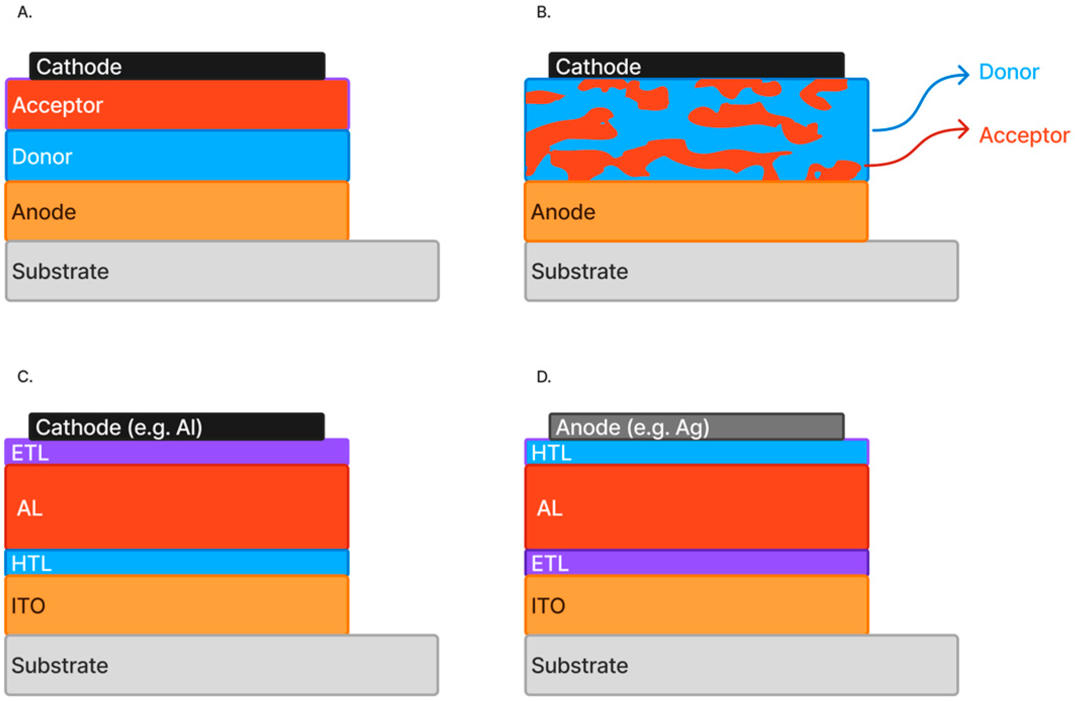
2. Analysis of Organic Solar Cell Structure

OSCs operate using thin organic films that convert solar energy into electricity via a photoactive layer positioned between two electrodes. This active layer promotes charge separation by combining an electron donor, such as a conjugated polymer, with an electron acceptor like a fullerene derivative (Figure 2) [5]. The electrodes, comprising an anode and cathode, are responsible for collecting the generated charge carriers and delivering the current to an external load. To facilitate this, a hole transport layer (HTL) guides holes toward the anode, while an electron transport layer (ETL) channels electrons to the cathode [25]. Commonly, the active layer includes a donor material (noted for its low ionization potential) and an acceptor (with high electron affinity), arranged either in a planar heterojunction (PHJ) configuration (Figure 2A) or a blended bulk heterojunction (BHJ) structure (Figure 2B), the latter offering improved efficiency through a larger interfacial area between the two materials [26,27]. The transparent conductive electrode, typically indium tin oxide (ITO), is applied to a substrate to serve as the anode. The HTL is commonly poly(3,4-ethylenedioxythiophene):poly(styrenesulfonate) (PEDOT:PSS). However, alternative materials such as MoO3, NiOx, and V2O5 have been developed to address PEDOT:PSS’s drawbacks related to device stability [28]. An electron transport layer (ETL) is often added. The standard and inverted structure is shown in Figure 2C and Figure 2D, respectively.
In OSCs, the photovoltaic process begins when incoming photons excite electrons, enabling their transition from the donor’s highest occupied molecular orbital (HOMO) to the acceptor’s lowest unoccupied molecular orbital (LUMO), which leads to the formation of bound electron–hole pairs known as excitons [29]. For these excitons to contribute to electricity generation, they must dissociate, and the resulting charge carriers must reach the electrodes. This dissociation is facilitated by the electric field generated at the interface of the donor and acceptor materials, which drives electrons and holes in opposite directions toward their respective electrodes [30]. The overall power output of an OSC is influenced by various parameters, such as how efficiently charges are separated, the intrinsic properties of the donor and acceptor materials, and the configuration of the device itself [31]. Bulk heterojunctions yield superior efficiency compared to planar configurations. The rationale is because bulk heterojunctions possess a significantly greater contact surface area, hence optimizing the transport of electrons and holes [27].
Recent studies on OSCs have emphasized enhancements in efficiency and stability by innovations in materials and device architectures [32]. Tandem OSCs, which incorporate multiple photoactive layers designed to absorb different portions of the solar spectrum, have shown notable potential in significantly improving power conversion efficiency (PCE). The exploration of non-fullerene acceptors has been undertaken to enhance device stability and performance.

3. Life Cycle Analysis Methodology

According to the ISO 14000 series, the LCA approach is consistent with a process [33]. The method typically consists of four primary steps: (1) establishing the objective and scope of the investigation, (2) conducting an inventory analysis to quantify material and energy inputs, as well as outputs such as emissions and waste, throughout selected life cycle stages, (3) organizing and assessing these flows into relevant environmental categories through an impact assessment, and (4) interpreting the results to identify opportunities for enhancing environmental performance in product and process innovation (Figure 1).
Usually, LCAs are used to evaluate many renewable energy possibilities even if the degree of comparability changes with consistent scoping and open methodology reporting [34]. Though the approach is governed by global norms, scholars have considerable latitude in how they conduct testing, which could affect the outcomes. Fthenakis et al. [35] has offered methodological guidelines for LCAs of PV technologies to solve this problem. These recommendations emphasize the importance of reporting important elements including the study’s objective and functional unit, system boundaries, methods and tools used (especially if not process-based), geographical and climatic conditions (e.g., irradiation levels), device efficiency, system performance, product lifetime, degradation rates, site of manufacture, type of system (e.g., rooftop or ground-mounted), data timeframe, study representativeness, assumptions about major input production, commissioning entities, and the method for calculating the energy payback time (EPBT).
Developed by the same research group, the 2020 version of the Methodology Guidelines on Life Cycle Assessment of Photovoltaic Electricity shows notable increases in the openness and strength of life cycle assessments for PV systems. A major modification is the addition of a wider spectrum of environmental effect indicators, including acidification, particle pollution generation, resource depletion, and water use. This makes it possible to thoroughly assess sustainability. The standards also include the non-renewable energy payback time (NREPBT). The measurement shows the time a PV system needs to offset the non-renewable energy used in its manufacture, hence prolonging the traditional energy payback time (EPBT). The updated suggestions underline the need for more openness in reporting, stressing the need for careful record-keeping of elements, including the kind of technology, system design, module efficiency, degradation rates, irradiation levels, and data sources to enhance consistency and reproducibility. The criteria update LCI data for particular PV technologies depending on present commercial production lines, therefore enhancing the representativeness of the evaluations. By including system-specific and geographic elements, including local climate, installation type, and operational performance, they underline the need for producing regionally accurate and pertinent LCA findings [36].
Recent research has underscored both progress and persistent issues in the transparency and comprehensiveness of LCAs for OPV technology. While certain LCA studies present essential components such as system boundaries and functional units, critical aspects like degradation rates and comprehensive methodological reasons are frequently inadequately reported. Valiente et al. [37] examined the temporal degradation of organic solar cells utilizing an ITO/PEDOT:PSS/P3HT:PCBM/Al configuration, highlighting the influence of manufacturing components on device longevity. The absence of standardized inventory data in commonly utilized databases complicates the execution of comprehensive life cycle assessments for organic photovoltaic systems. Inconsistent processing and manufacturing procedures, which remain unstandardized across the sector, exacerbate the situation. The environmental efficacy of OPV devices is greatly affected by their operational lifespan. Al-Ahmad et al. [38] underscored the necessity of incorporating degradation rates in LCA methodologies to accurately evaluate the enduring environmental impacts of OPV technologies, highlighting the significance of the electron transport layer in the deterioration of OPV cells.
Researchers often rely on data from laboratory-scale or plot-scale operations, prior published studies on comparable technologies, or theoretical predictions based on stoichiometric equations and default values extracted from current chemical data as a workaround. Though they may exaggerate harm or underestimate scalability, these methods nonetheless offer valuable insights into present environmental performance.
Academic research often examines two primary methodological approaches to LCA: consequential and attributional. Attributive LCAs, based on total data, reveal the environmental inputs and outputs connected to the current life cycle of a system and its subsystems. Conversely, consequential LCAs use marginal data to project changes in environmental flows in response to demand changes. Current LCA studies on OPVs usually use the attributional method. Rather than forecasting changes dependent on future market demand fluctuations, these studies seek to evaluate the environmental impact of OPV products during their complete life cycle.
Table 1 presents key LCA studies on OSCs, which differ substantially in methodology, device configuration, and choice of functional unit (FU), ranging from 1 m2 of active area to 1 Wp, 1 kWp, or total lifetime energy output. To enhance comparability, all studies were normalized to a common FU of 1 m2 of module area. For cases originally using power- or energy-based FUs (e.g., [39]: 1 Wp; [40]: 1 kWp; [41,42]: total kWh), equivalent surface areas were estimated using reported or assumed power conversion efficiencies (5–6%) and a standard irradiance of 1700 kWh/m2/year over a 20-year lifetime. This harmonization enables more consistent comparison of metrics such as EPBT, CED, and GHG emissions. Given the significant variability in system boundaries (e.g., cradle-to-gate vs. cradle-to-grave), regional electricity assumptions, and LCIA methodologies, a full quantitative meta-analysis was not performed. Instead, a qualitative harmonization strategy was adopted by (i) applying area-based normalization, (ii) clearly documenting methodological assumptions in Table 1, and (iii) identifying where results were affected by location-specific power mixes. As a result, environmental indicators such as EPBT and CED should be interpreted within the specific methodological context of each study.

4. Analysis of the Life Cycle of an OSC

Researchers frequently depend on data from laboratory- or pilot-scale operations, previously published studies on analogous technology, or theoretical forecasts derived from stoichiometric equations and standard values obtained from existing chemical data as a substitute [46]. Although they may overstate detriments or undervalue scalability, these approaches still provide significant insights into current environmental performance [47].

4.1. Raw Material Extraction

This phase is selected as the initial stage of the cycle for its precedence within the product’s production cycle and due to its significance as the foundation of a product’s environmental sustainability [48]. Modern research places significant focus on the concept of sustainable or cyclical economies. It is essential to eliminate environmentally harmful elements and implement measures for their removal, as previously executed with chlorofluorocarbons [49]. Commonly employed materials in OSC fabrication include substrates like polyethylene terephthalate (PET), transparent electrodes such as indium tin oxide (ITO), hole transport layers like PEDOT:PSS (poly(3,4-ethylenedioxythiophene):poly(styrenesulfonate)), active layers composed of polymer–fullerene blends, and aluminum as a back electrode [50].
PET is notable for its high recyclability and potential for use in closed-loop recycling systems [51]. However, the main limitation to achieving this lies in current collection inefficiencies and underdeveloped waste management infrastructure. PEDOT:PSS, a conductive polymer widely used in OSCs, has also been identified as recyclable and, in some formulations, exhibits self-healing capabilities [52]. Additionally, aluminum is a well-established example of a metal suited for closed-loop recycling, with extensive studies supporting its circular use [53].
In conclusion, the predominant materials extracted for OPV manufacture are entirely recyclable, with several capable of undergoing almost endless cycles. This renders the cells economically efficient and, more importantly, environmentally sustainable.

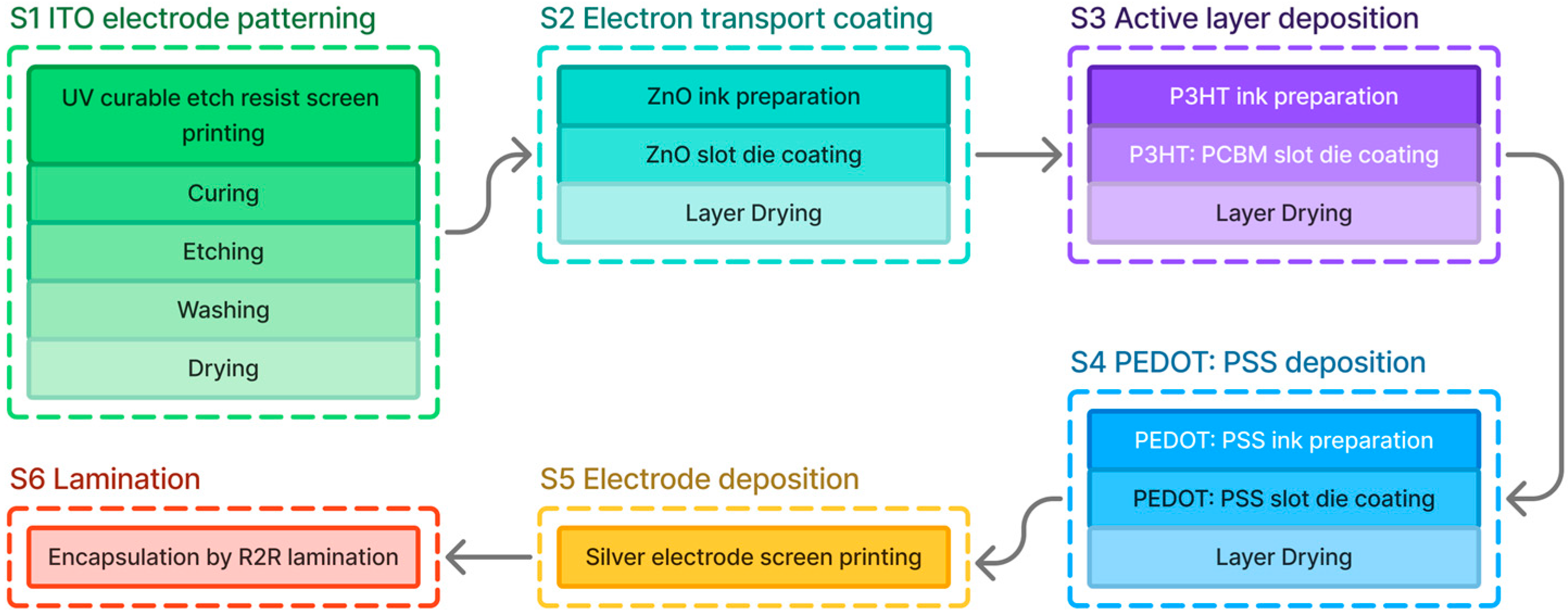
4.2. Manufacturing and Processing

A key benefit of OSCs lies in their compatibility with roll-to-roll (R2R) processing, which leverages their inherent flexibility. This manufacturing approach involves multiple printing techniques, which are typically structured around the complete production workflow. The process can be generally categorized into three main phases:
  • Wet film formation;
  • Processing during or after formation;
  • Lamination.
Espinosa et al. [54] detailed this workflow more specifically, outlining it as a six-step sequence, as shown in Figure 3.

4.2.1. Wet Film Formation

In the context of OPVs, four contact-based printing techniques are commonly explored for wet film formation: gravure, flexographic, rotary screen-printing, and flat-bed screen-printing [55]. Gravure printing operates at high speeds (up to 15 m/s) using low-viscosity inks, with print quality influenced by parameters such as ink flow, web speed, and applied pressure. Ink is transferred from engraved cells on a metal cylinder to the substrate, aided by surface tension and pressure from a secondary roller. Excess ink is removed by a doctor blade, ensuring only the desired amount remains in the cavities [56,57]. However, this method is not frequently used in solar cell fabrication due to its limitations. Flexographic printing, unlike gravure, applies ink from raised surfaces on flexible plates (rubber or photopolymer). Ink is metered via a ceramic anilox roller and then transferred to the substrate. This roll-to-roll (R2R) technique has recently been applied in printing conductive grids and modified PEDOT:PSS with feature sizes suitable for ITO-free OSCs [56,57].
Screen-printing delivers significantly thicker wet films compared to other methods, making it suitable for high-conductivity printed electrodes. The wet film thickness can range from 10 to 500 microns. The technique exists in two forms: flat-bed and rotary. In both, a squeegee forces ink through a mesh to form a pattern, but rotary screen-printing, employing a cylindrical screen and internal squeegee, offers higher speed and resolution. While rotary methods are ideal for industrial use, flat-bed printing remains valuable in research settings due to its lower cost and flexibility [55,57].
Meniscus coating provides non-contact deposition of continuous wet films by feeding ink to a meniscus formed between a coating head and the web. Unlike printing, which allows for 2D lateral patterns, coatings typically provide a uniform layer thickness (0D). Slot-die and knife coating are the main R2R-compatible methods. Knife coating uses a reservoir and blade to control the thickness as the substrate passes beneath, while slot-die systems deliver ink through a narrow slot using a pump, allowing for precise control based on ink properties and web conditions [57,58]. Inkjet printing, a contactless deposition method, has gained attention for its precision, material efficiency, and flexibility. It has already been used to deposit active layers like P3HT:PCBM in polymer solar cells. Despite its promise, challenges remain, such as ink flow consistency, nozzle clogging, and layer uniformity, but ongoing research continues to enhance the performance and reliability of this technique [59].
While each deposition method offers unique technical advantages, their environmental profiles can vary significantly. Inkjet printing, for example, although material-efficient, tends to have lower throughput and higher energy intensity per unit area compared to roll-based techniques, potentially increasing its environmental burden per Wp. Furthermore, issues such as nozzle clogging and solvent formulation can lead to yield losses and material waste. In contrast, gravure and flexographic printing are more compatible with high-speed R2R manufacturing, improving scalability and material utilization, though the former may involve more complex cleaning processes and higher initial setup energy. Screen-printing, particularly in its rotary form, is associated with thicker film deposition, which can be advantageous for electrode layers but may result in greater material use. Slot-die coating offers precise control with relatively low waste and is often considered one of the most environmentally favorable R2R-compatible techniques when optimized for ink use and drying energy. However, comprehensive, harmonized LCAs comparing these methods under consistent boundary conditions remain limited in the literature.
Any of the techniques mentioned above may be appropriate for the fabrication of the layers utilized in the conceptual products in Section 5..

4.2.2. Post-Coating Processing Techniques

There are two main examples of R2R processing. The double slot-die coating process facilitates the creation of complicated segregated wet films with intricate lateral and horizontal topologies [57]. Another notable innovation in coating techniques is the differentially pumped slot-die system introduced by Alstrup et al. [60]. This approach enables the simultaneous delivery of multiple ink formulations through a specially designed slot-die head, offering greater flexibility in multilayer film deposition. Once the wet film is formed, it typically undergoes a drying phase. This often involves thermal treatment to remove residual solvents, allowing the desired material to solidify at a specific thickness. Some modern ink formulations, particularly solvent-free adhesives, utilize UV curing technologies that can initiate the hardening process even before complete solvent evaporation. Drying and curing remain critical stages in OPV manufacturing, with techniques like hot air drying, UV curing, and screen-printing of silver back electrodes playing essential roles in achieving stable device performance [24]. The comparison of power conversion efficiency between silver inks and only UV-curable ink revealed that the latter achieved the maximum power conversion efficiency (PCE). Another study indicated that solvent-based silver inks degraded, in contrast to UV-curable ink and a specially developed water-based ink, which remained stable [61].
Thermocleaving is a post-deposition procedure occurring subsequent to the application of active or other functional layers by slot-die coating methods [62]. In R2R OPV manufacture, thermocleaving with high-intensity light is utilized to eliminate solubilizing polymer side chains, thus improving the electronic performance and durability of the final device [50,62]. Thermocleaving a polymer in an oven at 140 °C required four hours, rendering the process impractically slow. Conversely, utilizing a bespoke high-intensity narrow-wavelength light yielded significantly accelerated web speeds between 0.2 and 0.4 m/min. Ultra-short lasers have been introduced [63]. Pulses spanning from picoseconds to femtoseconds are used. These innovative selective laser-patterning techniques hold potential for the R2R production of solar cells [64]. Brief pulses produce minimal heat, enabling the meticulous removal of a small layer without damaging the underlying surface. Initial solar cell reports predominantly utilize ITO patterns on glass and PET [65]. This technology, however, has yet to exhibit functionality. Eliminating applied substances is generally not favored in manufacturing when avoidable. However, it may still demonstrate utility in niche products. Scribing is a significant advantage [66]. It may assist future OPV modules with significant geometric fill factors. It can achieve geometric slot-die coating and screen-printing fill factors ranging from 45% to 67% [66]. Nonetheless, it may achieve an accuracy of 85% with great precision [57]. It is improbable that it will progress beyond this threshold [66].

4.2.3. Final Lamination and Module Assembly

According to the lamination procedure described by Espinosa et al. [54], an adhesive layer was applied to the barrier foil using a lamination technique. The dimensions of the adhesive and foil were selected strategically at 305 mm in length and 298 mm in width to prevent adhesive buildup on the rubber rollers due to minor misalignments during processing. To ensure optimal alignment and process control, the barrier foil can include a pre-lined adhesive layer and be trimmed on one side (e.g., to a 250 mm width) to expose functional areas while securing the remaining sections during lamination. In R2R production, silver bus bars are typically integrated to establish electrical contacts and enable current–voltage (IV) characterization.

4.3. Transportation

The logistical structure of OPVs offers significant economic advantages due to their reduced weight compared to silicon alternatives. Their weight ratio is projected to be no less than 10 to 1 [67]. The weight differential and the significantly reduced thickness and volume of thin-film products greatly enhance their logistical capacity.
The American Bureau of Transportation Statistics defines freight density as the volume-to-weight ratio of goods being transported [68]. This metric helps shipping companies calculate the dimensional weight, which they use to determine the chargeable weight for a shipment. The final shipping cost is then based on this calculated weight, which may vary between different carriers and service levels. Due to their significantly lower volume and mass, often up to ten times less than conventional alternatives, OPV devices can greatly reduce external shipping costs, contributing to lower overall product costs.
To streamline shipping charges, the freight industry categorizes shipments into standardized classes. In the USA, for example, the National Motor Freight Traffic Association (NMFTA) assigns freight classes based on parameters such as dimensions, density, handling difficulty, market value, and risk of damage or spoilage [69]. These classifications are crucial for ensuring consistent pricing across carriers, brokers, and warehousing services. Table 2 delineates the several ranges that ascertain the final cost.
The costs are mitigated even if the enterprise opts to retain transportation internally. The weight-to-value ratio of the products significantly enhances efficiency, allowing for greater delivery of goods per unit of fuel and storage space in the truck. This also applies to the shipping industry and air transport [71].

4.4. Usage and Retail

OSCs are designed for mass production in rolls. They are inexpensive, available in large quantities, and have uniform active layer material suitable for many applications. Each design outlined in this paper requires several alterations in its manufacture and several types of materials for fabrication. An active sunshade could be optimized by incorporating multiple layers designed to absorb different segments of the solar spectrum, allowing for the fabrication of colored layers tailored for specific light wavelengths [72].
The application and commercialization of such technology would depend on the strategies of individual companies. Organic portable solar panels are generally easy to use and are primarily suited for outdoor activities such as camping. However, depending on their design, they can also serve as compact off-grid power solutions to help reduce household energy costs. Another instance is the retail of the active sunshade. It may encompass electronic retailers, expansive hardware establishments, and supermarkets featuring a department dedicated to home and automotive hardware. All three merchant channels are valid, and the market’s specific characteristics will dictate the most appropriate selection. Furthermore, such decisions also impact the marketing dimension of the product.

4.5. Waste Disposal

A key goal in the development of OSCs is to ensure high recyclability and reduce end-of-life (EoL) environmental impacts. Unlike traditional crystalline silicon solar modules, which use adhesive lamination that complicates material separation, OSCs are typically not laminated in the same manner, allowing for easier disassembly and potential recovery of components [73].
Crystalline silicon PV modules are constructed from layers of glass, polymer encapsulants (e.g., EVA), and backsheets bonded together. While aluminum frames can be manually removed and glass recovered (up to ~85% in some facilities), the encapsulants and backsheets are generally not recyclable due to thermoset properties and chemical contamination. Material recovery efficiency for crystalline silicon solar modules ranges from 70–90%, with silver recovery rates often below 50% without specialized equipment [74].
In contrast, OSCs offer potential recyclability advantages due to their use of lighter, non-rigid materials such as PET substrates and polymer-based electrodes (e.g., PEDOT:PSS), along with non-toxic active layers. For instance, aluminum, commonly used as a back electrode in OSCs, is one of the most efficiently recycled materials, with recovery rates exceeding 90% in closed-loop systems. PET films used in OSCs are technically recyclable, but current global PET recycling rates remain around 25–30%, hindered by inefficient collection systems [75]. While OSCs contain far less material mass than silicon modules, dedicated recycling routes are still under development.
Importantly, OSCs avoid toxic metals like cadmium and lead (common in some thin-film technologies such as CdTe and CIGS), reducing potential EoL hazards. However, certain polymers and solvents used in OSC fabrication may present disposal challenges and require further research on safe degradation or reuse pathways.
Thus, while the EoL infrastructure for OSCs is still nascent, their simpler architecture, non-toxic composition, and compatibility with closed-loop recycling concepts suggest favorable sustainability prospects when compared quantitatively with established PV technologies.

5. Concept Products of OSCs

While Section 3 and Section 4 provide a formal review of LCA methodologies and data for OSCs, this section presents a set of conceptual OSC-based products intended to explore potential applications and market positioning. These proposals are not meant as finalized engineering designs but rather as speculative extensions informed by the technical and environmental characteristics of OSCs discussed earlier. As such, they serve to highlight innovation opportunities and practical challenges in real-world deployment contexts.

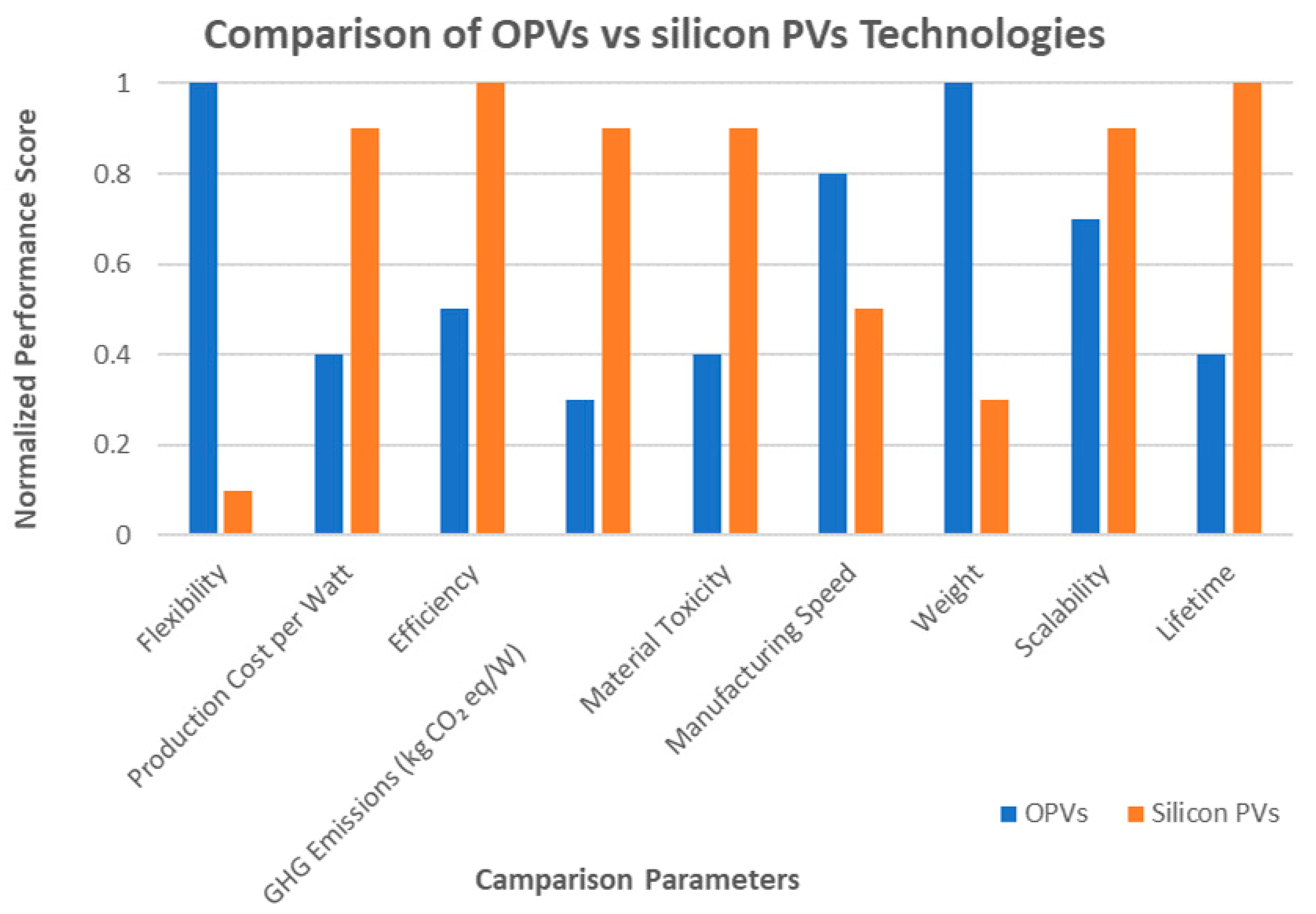
5.1. OSC Sustainability Profile

Based on three fundamental pillars, i.e., economic, environmental, and mass production capabilities, OSCs offer a compelling option for product design [76].
The initial assertion to be made is that OSCs provide significant benefits in terms of their mass manufacturing capabilities. Cost-effective and effective methods, including R2R printing and solution processing, can be used to fabricate these cells. The aforementioned production processes’ scalability and cost-effectiveness make OSCs a desirable option for large-scale production, which lowers the cost per unit and makes it easier to incorporate solar energy into a variety of products [77].
Furthermore, a key component of contemporary product design is the incorporation of environmental sustainability. The production of OSCs uses organic materials, which are generally recognized for being more environmentally friendly than the heavy metals used in other PV systems [78]. The components described above are non-toxic and readily available, which lessens the environmental impact associated with solar cell manufacture [76].
Moreover, less hazardous elements are frequently utilized in the manufacturing procedures that produce OSCs, which also result in lower GHG emissions. This is in line with the worldwide need to mitigate the negative environmental effects associated with energy technology [79].
One fundamental element is economic sustainability. Because OSCs are made of affordable components and can be produced in large quantities, their economic viability appears promising. The practicality of product design may be increased by the cost-effectiveness of solar power integration in a variety of goods, which can drastically lower initial expenditure [80]. Furthermore, OSCs’ environmentally friendly qualities complement the objective of making renewable energy more widely available to consumers, which will promote both environmental and economic sustainability by reducing carbon emissions over time [67].
According to the LCAs, OSC technology is capable of achieving long-term sustainability as long as the right materials and procedures are produced or used. The ideas and studies, which are based on sustainability, might lead to technology that lowers the barrier to entry into the solar industry for passive power production. More products will have the option to integrate solar systems into their functioning and design in order to increase productivity or lower power consumption. Due to all of the above and without the damaging effects on the environment that uncontrolled mass production may have, this economic sector may move from a specialty to a standard with the right waste management and infrastructure.
A qualitative comparison between OPVs and silicon PVs is presented in Figure 4, illustrating the unique strengths of OPVs in product-oriented applications. Key parameters were normalized based on representative values from the recent literature [76,77,78,79,80], providing an intuitive visual overview across diverse metrics, including flexibility, production cost, and efficiency. While OPVs demonstrate clear advantages in flexibility, weight, and environmental impact, certain limitations remain. Their efficiency and operational lifetime are currently lower than those of silicon PVs, largely due to the intrinsic properties of organic materials. Scalability also poses challenges, particularly in maintaining performance during large-area fabrication. However, ongoing research in material stability, encapsulation techniques, and tandem cell architectures is rapidly improving these metrics, positioning OPVs as a promising complement to traditional photovoltaics, especially in niche and integrated applications.
The following sections expand on the previous assessment of OSCs by looking at three products that make use of the most important advantages of the technology. Optimizing the utilization of the OSCs’ properties was the goal that guided the product selection. Products that already existed were chosen because they offered accurate computations and reasonable assumptions. The products were picked because they made the best use of organic cell technology. The first two products provide a fresh perspective on already-existing products. To achieve similar results more affordably and sustainably, they use organic solar systems instead of silicon cells for energy generation. Utilizing all sun-exposed surfaces, the third product applies an architectural design idea that has already been proven effective in car design.
While these products present conceptual OSC-based products with potential advantages in terms of material cost, flexibility, and form factor, it is important to note that these claims are not supported in this study by a formal LCA or simulation-based modeling. The environmental and economic comparisons are qualitative and based on general trends in OSC fabrication, market pricing, and known material properties. Key parameters such as embodied energy, GHG emissions, end-of-life options, and long-term reliability have not yet been quantitatively evaluated. A comparative LCA, particularly against silicon-based portable systems, is recognized as a valuable step toward strengthening the assessment of these products’ sustainability profiles. As such, it is proposed as a key direction for future work.

5.2. Design and Concept Philosophy

There are two product concepts that take advantage of OSCs’ benefits. Breaking into the market is one of the most challenging jobs for any new product or technology. The world has just recently shifted towards renewable energy sources; therefore, it has taken over a century for solar panels to become significant in energy production. However, silicon solar cells dominate the solar industry. Therefore, the challenge for each new solar cell technology is to compete with or set itself apart from the market leader.
In order to counteract and set OSCs apart from silicon solar cells, three hypothetical products will be put forward. However, as is frequently the case, the truth may be somewhere in the middle. It is possible that a combination of these items will be even more beneficial than each one alone. The following are OSCs’ primary benefits:
  • Flexibility;
  • Low production cost;
  • Non-toxicity;
  • Abundant materials;
  • Fast and efficient production.
These features depict a technology that closely mimics the electronics industry in both manufacturing and application. The foundations of the contemporary electronics industry are the ideas of extremely low production costs, plentiful resources, and replacement rather than maintenance. This review focuses on the approach required to join the market for solar energy generation rather than delving into the complexities of business–consumer relationships or economic policy and politics. Making products appealing to investors is the most harmonious strategy to break into any market. Because they are human, investors are more inclined to accept a notion if it does not conflict with their past experiences. This implies that the best possibility of a new electronic product succeeding is for it to follow the way the electronics business operates in this day and age.
Because of the nature of their technology and materials, the goods described below are designed with these concepts in mind. In addition to taking economics into account, the proposed products are designed with sustainability in mind, ensuring that all materials used can support a closed-loop life cycle. Specifically, three key innovations are highlighted:
  • A compact, foldable portable solar panel designed for ease of transport;
  • An automotive solar umbrella, also referred to as an “active sunshade”;
  • A solar-energy-generating window film suitable for electric vehicles (EVs).
The technology of OSCs is optimized for all three of these products. The use of OSCs can significantly improve portable solar panels, which are now available as thin silicon devices. The primary advantages of differentiation are a significant reduction in costs due to the utilization of organic cells and the device’s weight.
An active sunshade/solar umbrella maximizes its orientation towards cost minimization while adhering to the same line of thought as the preceding product idea. The fact that the product’s silicon equivalent is now available on the market indicates that it is a feasible consumer good, with production, marketing, and research all playing a role in its success.
Last but not least, the manufacture of automobile windows in the automotive sector might be complemented by solar window tinting. This is a tertiary product for automobile glass, which might significantly improve the economics of EV energy. Given that range is a significant barrier to widespread adoption, manufacturers may find it highly appealing to include an additional power-producing system into EVs. The market for electronic vehicles is still in its infancy, and every system created to support it can bring the industry one step closer to integrating the technology generally.

5.3. The Transportable Solar Panel

The first idea examined is a substitute for portable solar panels made of crystalline and amorphous silicon. This idea takes advantage of a solar panel’s basic operation, but with a twist, in an effort to further reduce the upfront installation costs. The downside is that the semi-conductor is organic and applied to flexible substrates rather than being factory-encased [81].
Organic cells are used in the solar panels to maximize mobility and affordability. The product’s positioning is to provide equivalent power generation at a substantially lower initial cost than purchasing a transportable solar system. Solar cells made of silicon are known to be more efficient than those made of polymers. Therefore, by just becoming broader, the product may use its advantages of its weight and inexpensive cost to supply the same wattage without relying on the advancement of scientific study [82]. A brief overview of the current portable solar panel market highlights significant growth potential. According to a report by Industry ARC [83], the market is projected to reach approximately USD 1.3 billion by 2027, growing at a compound annual rate of 17.5% between 2022 and 2027. Contributing factors include supportive government policies aimed at expanding access to off-grid energy, increasing use of mobile and wireless energy-efficient devices, and the urgent need to reduce dependence on fossil fuels.
Additional drivers of demand include the rise in consumer investment in solar-powered technologies, advancements in flexible and thin-film electronics, and the shift toward electric and hybrid transportation. Of particular note is the surge in interest for foldable solar panels, which are enabled by recent innovations in flexible electronic materials. These panels offer benefits such as compactness, ease of transport, and compatibility with various electronic devices, from GPS units to camping tools and field communication systems.
The growing appeal of lightweight and easily deployable panels has led to increased adoption across diverse applications. A notable development occurred in February 2021, when researchers at Pusan National University in South Korea unveiled a foldable solar cell prototype capable of withstanding over 10,000 folding cycles while maintaining efficient energy conversion. Such advancements are expected to fuel continued market growth, particularly in response to rising interest in ultra-thin, flexible energy technologies [83].

5.3.1. Working Principle and Applications of the Transportable Solar Panel

With a few adjustments to optimize the necessary features, the aforementioned solar panel operates on the same principle as conventional silicon panels. Specifically, the design must be resilient enough to endure any mild weather situations. The consumer anticipates that the device can be kept outside during mild weather because it is not sustainable to deal with the inconvenience of uninstalling the entire system in response to minor, frequent changes in the climate [84].
According to the previous mean, its operating conditions should be appropriate for a temperature range of −10 °C to 50 °C, just as its silicon counterpart [84]. Along with being lightweight and flexible, the product must also be resistant to rain and mild hail. Additionally, polymer cells should be made to withstand heat. Furthermore, the product’s basis technology’s light degradation issue needs to be greatly addressed to provide it a comparable longevity to its rivals [67].
The product’s baseline viability is the mathematical threshold at which purchasing a new one every X years is no longer economically feasible. All of the major portable panel manufacturers, such as Bluetti, Anker, and Rocksolar, assert that their devices have a 25-year lifetime. This implies that the proposed product would require at least half the lifespan for half the price.
There are countless uses for flexible panels because of their form flexibility and low weight, which may allow them to be used on surfaces that traditional panels are unable to cover [85]. One derivative product must be taken into consideration for the purposes of this work. The product is a tent solar cover. Since folding cells harms their structure, resulting in decreased efficiency and quicker disintegration, the flexible panel cannot be crumpled widely on its own [31]. Therefore, it could be useful to have a tent cover that uses solar electricity. Summer campers could be able to utilize the tent throughout the day thanks to this design, or at the very least, it might serve as a charging station for small electronics.

5.3.2. Design Specifics of the Transportable Solar Panel

The purpose of inexpensive, interchangeable products is to prevent the organic cell from degrading due to heat, light, chemicals, and mechanical forces. Unlike biological silicon, crystalline silicon is a resistant substance in and of itself. The fact that components like an ITO are not required for the manufacturing process of such a design is a straightforward illustration of the OSC’s cost efficiency [86]. One of the most expensive parts of making panels is the ITO; hence, the concept of designing a panel without it drastically reduces costs. Its qualities and viability enable the concept to be organically included into our own design, utilizing the design’s cost savings [87].
To preserve flexibility, only metal and plastic substrates are taken into consideration for this specific product. Thin, flexible metal foils that are less than 125 micrometres thick are frequently used to create flexible solar cells [88]. The exceptional degree of flexibility of the foil is a result of the high ductility of metals. Among flexible metal substrates, stainless steel foil is widely favored due to its strong resistance to chemical degradation, stability under high temperatures, and affordability. On the other hand, commonly used plastic substrates include polyethylene terephthalate (PET), polyimide (PI), polycarbonate (PC), and polyethylene naphthalate (PEN), each offering distinct advantages for specific organic electronic applications [31]. Because of its versatility and limitless possibilities for recycling, PET is by far the greatest option.

5.3.3. Cost Analysis of the Transportable Solar Panel

To remain competitive with conventional silicon-based solar cells, organic portable cells must achieve at least a 50% reduction in cost. According to a 2020 ThinkEpic report [89], current market prices for solar systems range between USD 0.75 and USD 2.50 per watt. Consequently, to be a cost-effective alternative, organic-polymer-based cells should target a range of approximately USD 0.37 to USD 1.25 per watt, aligning with consumer pricing benchmarks such as those found on Amazon. In this context, comparing the cost-efficiency ratios (i.e., power output per USD) of organic and silicon solar technologies becomes essential. Unlike earlier design-oriented analyses, this section focuses on evaluating economic feasibility in terms of price-to-performance metrics. Compared to silicon ones, which have an efficiency of 20–25%, OSCs have an efficiency of 15–20% [90]. Assuming an average of 17.5% for OSCs and 22.5% for silicon, both are in the middle of their range.
For the same price, the product can be viable. It is evident from the computation that an organic system with half the cost and more than double the efficiency of silicon is possible. Since the system’s efficiency is theoretically more than half, the OSC would generate a silicon solar cell with an efficiency of 35% at twice the size.

5.3.4. Market Positioning of the Transportable Solar Panel

This product’s primary goal is to reduce the initial cost of a portable power generation system. As demonstrated by the decline in the price of solar panels between 2010 and 2022, the democratization of products has led to profit in every product up to this point. In theory, portable power-producing devices work similarly. According to Madsen et al. [91], the market has grown exponentially, which is directly related to the initial cost and cost-effectiveness of solar systems.
Since weight and storage capacity are important considerations for campers and outdoor enthusiasts, design variables can also have a significant impact on system sales. The primary competitive advantage of OSCs that enables them to rule this specific market segment for outdoor gear comprises these two characteristics.

5.4. The Solar Sunshade/Solar Umbrella

The second idea is similarly rather straightforward. The device is an internal automobile membrane that attaches to a port to supply energy to or power the car’s air-conditioning system, which keeps the cabin warm in the winter and cool in the summer [92]. It is a combination of OPVs and sunshades. The concept seems promising since the technology is already available on the market and the application has been tried and proven [92,93,94].
For this concept, two designs are being evaluated. The first is a standard, inexpensive sunshade with an organic thin film included into the design. It is a solar shade that produces energy, and it is the most basic of the two concepts. The concept is self-evident. For charging electrical gadgets, the product may have a built-in tiny charger or utilize a specially made vehicle port. Since electronic systems are being incorporated into automobile designs at a rapid pace, adding such a connection might be rather easy.
The second concept is an inside canopy for a solar-powered vehicle. Two folding extensions that shade and use the front seat windows can further enhance the interior-based umbrellas. The concept of a converter and cable for charging electrical gadgets remains the same, as does the connection to the vehicle. Since the automobile shields the gadget from rain and wind, it was decided to incorporate the product inside the vehicle. Since weather speeds up cell deterioration, external automobile umbrellas were not taken into account. This is true even for modern umbrellas made of textiles. There would be a noticeable decrease in efficiency even with a small amount of snow or tree leaves.

5.4.1. Working Principle and Applications of the Sunshade/Solar Umbrella

The device operates on the same idea as an OPV solar cell. Its application is the twist. The non-toxicity of polymer solar cells makes them ideal for any application, including prostheses and human surroundings. The membranes are located inside the car to shield the cells from weather-related deterioration.
There are two purposes for the sunshade. The first is using a conventional sunshade to shade the interior of the car. Where the product has an advantage over rivals is the second use. The gadget can charge anything that is connected to it by turning sunlight into power. This covers all electrical gadgets, such as phones and power banks, but more significantly, by looking farther into the future, it may be advanced. Range issues are a well-known issue with EVs. Owners of EVs may be extremely interested in a solution that helps alleviate that issue. The market for solar sun blinds will expand in tandem with the demand for electric cars.
Additionally, it is anticipated that industrialized nations’ economic development would be accelerated by an inadequate electricity grid capacity [95]. All markets that concentrate on independent power production will undoubtedly expand more quickly in the event of an inadequate grid. Additionally, consumers find independence from the grid appealing, which will help the marketing efforts of the producing companies [96].
Regarding applications, the product is not limited to automobiles. If the integrated inverter design is adhered to, the umbrella might function as a power generation resource as long as there is light exposure. Since the product design may incorporate a vehicle-specific design or a generalist strategy by incorporating an inverter that feeds electrical ports, the precise purpose is still up in the air.

5.4.2. Design Specifics of the Sunshade/Solar Umbrella

The sunshade’s design is optimized to take use of the technology’s benefits and get rid of its drawbacks. Thermal stability is one of the main issues facing OSCs in general, as well as the product. According to a recent work by Qi et al. [97], the heat stability was enhanced while preserving the initial PV performance by adding a moderate quantity of random copolymer PY to the active layers. Their characterization’s findings showed that the PY affected the blends’ crystalline, morphological, and optical characteristics. In addition to disrupting the aggregation of photovoltaic polymer chains, the amorphous random copolymer that was dispersed across the polymer domain also improved the acceptor order, leading to a more noticeable phase separation. Under thermal stress, the incorporation of PY was found to reduce polymer chain mobility and inhibit the crystallization of both donor and acceptor materials, contributing to improved thermal stability and a more robust active layer morphology. As a result, devices based on the P3HT:O-IDTBR system with a 10% PY content demonstrated photovoltaic performance on par with the control setup. Notably, the modified device preserved over 70% of its initial efficiency after being subjected to 150 °C for eight consecutive days [97]. This performance suggests strong suitability for real-world applications, where operating temperatures can reach approximately 50 °C for extended periods during summer months.
Because PSCs are flexible, there is some leeway in how the product is used, stored, and applied. Manufacturers of OSCs want to use R2R techniques to produce these materials in large quantities. This implies that the items may be folded in some situations and kept similarly to conventional foil products. Despite their flexibility, thin films lose part of their effectiveness when squeezed or crumpled [98]. This restricts the product’s design, since it must be folded and unfolded in particular ways. These guidelines are not usually followed by customers, which might cause product wear and tear. Unfortunately, certain geometries, such as those seen in portable solar panels, compartmentalize the panels so they may be folded and stowed at these precise locations and employ lines of material instead of printed material.

5.4.3. Cost Analysis of the Sunshade/Solar Umbrella

The cost per unit was computed in this section. Estimates were employed when the components were still in the research stage, either by the creator of the components or by integrating research data for this paper’s objectives. For the concept to match the estimated cost, a few presumptions and compromises must be made. First are the sizes of the windscreen and door windows; the industry average for each automobile type is shown in the data in Table 3.
Table 3 indicates that four different thin film sizes must be manufactured. OSCs are estimated to cost between USD 48 and 138.90 per m2 [99]. The cost of solar cells dropped sharply between 2010 and 2020 [100]. For this reason, the lowest estimate, 48 USD/m2, was used in the computations. The truth may be much lower because this forecast predates the solar surge of 2010–2022.
It is supposed that the cells’ efficiency is about 15%. In a laboratory setting, the greatest reported efficiency is 19.2% [101]. As previously mentioned, the device must be capable of charging automobile batteries and gadgets. To determine the viability of such an undertaking, it is necessary to analyze the amount of energy that can be converted into electrical power.
The windows of smaller automobiles have a total area of 1.4 m2. According to the Australian Space Weather Forecasting Service, the solar constant is between 1358 and 1364 watts per m2 [102]. Standard Testing Conditions (STCs) were used to expose the 1.4 m2 system to 1000 watts of sunlight.
This corresponds to around a 200 W system at 15% efficiency. Thus, the system can generate 200 W/h. A typical electric automobile in 2023 uses around 0.198 kWh per km and has a battery capacity of about 60 kWh [103]. Accordingly, a km of range corresponds to an hour of exposure, taking into account that the average range based on capacity is 60 kW ÷ 0.198 kW/km = 300 km. With 5 h of exposure every day, the solar screen might generate 150 kilometres in a month. Larger automobiles correspond to 540 W systems, ceteris paribus, with just the surface area varying. For the sake of simplicity, it may be supposed that the kilometres achieved are about equal to those of smaller automobiles, even if 540 W per hour is produced.

5.4.4. Market Positioning of the Sunshade/Solar Umbrella

The market for car window power sunshades is where these two ideas belong. Technavio predicts that between 2022 and 2028, the market will grow at a CAGR of 15.74%. The market for these technologies is projected to expand by approximately USD 1396.61 million, driven by several key factors. These include the ability of window-integrated solar sunshades to enhance HVAC (heating, ventilation, and air conditioning) system efficiency, the growing amount of time people spend inside vehicles—boosting demand for in-car energy solutions—and the increasing popularity of premium and luxury vehicles [104].
Even when accounting for the narrower category of solar shading systems, which only partially overlaps with the technology in question, the global market was valued at USD 17.55 billion in 2019. This figure is forecasted to reach USD 21.35 billion by 2027, growing at a compound annual growth rate (CAGR) of 3.9% between 2020 and 2027 [105].
These items’ rivals include conventional umbrellas and sunshades, which have a similar function of blocking sunlight but do not have the ability to generate electricity. That is the competitive advantage on which this product’s marketing will be built. Additionally, the technology works well with hybrid and electric vehicles.

5.5. Window Tint for Electric Vehicles

This product’s primary concept is to use the technique of printing OSCs on automobile glass. According to Shukla et al. [106], OSCs are already becoming more popular as window membranes, full semi-transparent glass systems, and building-integrated PV systems. By placing thin-film technology on their surfaces, office buildings and other structures with big glass surface areas that receive a lot of sunlight provide the potential to generate energy. Businesses that have already used the technology with an efficiency just around 10% include Onyx Solar and Heliotek. A semi-transparent perovskite solar cell printed on glass has been developed [107]. The idea works precisely like an OSC that has been printed onto a glass substrate. In addition to providing shade for the vehicle, the semi-transparent cell generates power.
The connecting method and implementation are the two main issues facing the technology. If OSC foils are made with this goal in mind, they may be put directly to automobile glass like stickers, much like traditional films [67]. The other option is to print directly onto automobile glass, which would involve additional, albeit brief, steps in the production process. In any case, the power conversion mechanism would have to be built directly into the dashboard and doors, making the connection of a foil or directly printed cell difficult.

5.5.1. Working Principle and Applications of Window Tint for Electric Vehicles

The only difference is the surface used; otherwise, the operation is the same as that of a solar panel. Since the entire idea addresses a highly particular niche in the car glass and shading industry, the applications of such a specialized product are very restricted. Utilizing untapped surfaces for PV production is the idea’s guiding principle, which increases every structure’s energy efficiency and actively contributes to cost reduction by creating rather than merely enduring.
The membrane application technique, aftermarket foil, or integrated printing by the car manufacturer are the primary points of contention. Both approaches are already in use and have shown themselves to be profitable for both independent contractors and manufacturers. The first option, which many manufacturers now employ, is to physically tint car glass. The difference would be that the manufacturer would require an OPV printer to create the glass with a photovoltaic color.
The advantage of this approach is that, in practice, printing the cell on a window is the same as printing it on a glass substrate. Although the flexibility of OPVs has been the subject of much research, the stability of the cells is enhanced when using a glass substrate [31]. The second would be a roll of foil made by an aftermarket tint manufacturer and sent to window tinting experts for application.

5.5.2. Design Specifics of Window Tint for Electric Vehicles

The largest obstacle facing the product is its connection with the automobile. For this technology to be widely used, automakers must be sufficiently motivated to incorporate such a system. Theoretically, an electrical circuit that passes through the car is linked to the OSC printed on the inside of the window via its anode and cathode. An inverter is then attached to the circuit’s end to convert the current.
Last but not least, the longevity, end of life, and replacement are factors that are also crucial to the success of the product. Many studies and commercial R&D efforts have been devoted to improving the product’s longevity, which is a significant measure. It is estimated that a 30-year lifespan might be attained [108]. Even if the data is 33% off and the actual value is closer to 20 years, the product is still well within the typical lifespan of a vehicle due to the inherent discrepancy between theoretical values and reality. This implies that there will never be a need to replace the glass membranes.
According to Li et al., [108], OSCs have the ability to work for 10,000 h, or 1.14 years. The cost of the membranes would need to be within the consumer’s annual budget range, assuming that the membranes will need to be changed annually, which may be combined with an annual maintenance service.
It is impossible to overestimate the significance of cost-effectiveness for each hypothesis. If the membranes generate enough current to offset the cost, they become either a free buy or, better yet, an investment that saves the customer money, even if they need to be replaced annually.

5.5.3. Cost Analysis of Window Tint for Electric Vehicles

With an average size of 0.2 m2, a car’s rear side windows are similar to its front windows. Accordingly, a total of 2.2 m2 is accessible for smaller automobiles, and 4.7 m2 is available for larger cars [109]. Accordingly, assuming a 15% efficiency, the energy potential in full sun and in the correct direction is 330 W for smaller automobiles and 4.7 × 1000 × 15% = 705 W for larger ones [110].
These figures are predicated on ideal lighting and circumstances. A reasonable approximation would be to use 1.6 m2 for smaller automobiles and 3.9 m2 for larger ones, as the fact is that nearly half of the side windows will be in the light, depending on the sun’s location. This leaves 585 W for large automobiles and 240 W for smaller ones.
A membrane measuring 2.2 × 48 m2 costs USD 96, without including the installation fee, which varies greatly. The number for larger cars is 4.7 × USD 48 = USD 225.6. A typical foil membrane’s production costs are shown by these numbers. Additionally, automakers may decide to implement the procedure internally. The estimated expenses of a whole production system are examined in Gambhir et al. [111]. By examining each cost per m2 based on scale and production capability, a business may decide to purchase foil or produce it itself.

5.5.4. Market Positioning of Window Tint for Electric Vehicles

Vehicle window tints may be replaced with these solar tint membranes. They vie for market share in the window shading industry, but that is the extent of their comparison. A completely new method of designing automobiles is the solar tint, which generates energy from the windows of the vehicle, and all of this is achieved without sacrificing safety because foils are made of polymers, namely PET, in the majority of commercial uses. This is also how the product is positioned. The client invests in and purchases the organic tint in order to include a passive power generation system for their EV.

6. Discussion and Future Work

OPVs come in various forms, such as portable panels, solar blinds, and tinted films, and each type brings specific benefits and challenges. Still, across all applications, a few core priorities stand out, including stability, efficiency, production scalability, and, of course, cost-effectiveness. These factors are all closely connected and shape whether OPVs can succeed in real-world use.

6.1. Stability Under Environmental Stress

Before anything else, OPVs need to be stable under different environmental conditions. For example, thermal stability is essential if these devices are going to be exposed to heat. When the temperature rises, the internal structure of the materials, especially the active layer that absorbs sunlight, can start to shift. This can block the flow of charge, which reduces performance [67,112].
Light can also be a problem. Over time, sunlight can break down the materials used in OPVs. This issue, known as photostability, can limit how long a solar cell remains effective [67]. For this reason, testing how materials hold up under light and heat is an ongoing part of OPV research.
Chemical stability is another key concern. Organic materials often react with oxygen, water, or even light, which can lead to changes that reduce efficiency and shorten lifespan [112,113]. Researchers need to understand how these materials behave at both the surface and interface levels to design better systems that resist degradation.
Then there are mechanical and physical stability, which are especially important for flexible or wearable devices. Layers can crack or peel over time due to bending, stretching, or changes in temperature. These changes can interfere with charge transport and reduce performance [114]. To make reliable OPVs, we need a deep understanding of how different layers interact and how they respond to stress [67].

6.2. Balancing Efficiency and Cost

Improving the efficiency of OPVs while keeping them affordable remains one of the biggest challenges. If a solar cell can convert more sunlight into electricity, it would obviously be more valuable, but if it is too expensive to make, it will not be used widely [26,115].
To boost efficiency, researchers focus on designing better materials that can absorb more light and transport charges more effectively. For example, tuning the energy levels of organic molecules or adjusting donor–acceptor pairs has shown promise [116,117]. However, even the best materials will not matter if they are too costly or hard to produce at scale.
This is why material choice is such a balancing act. Organic materials often win out because they can be processed in liquid form and printed onto surfaces using simple techniques like inkjet or spray coating [55]. These methods cut down on waste and make large-scale production more practical, but only if the materials remain stable and compatible with mass production [31].

6.3. Scalability and Manufacturing Readiness

Techniques such as R2R printing, slot-die coating, and spray deposition help translate lab-scale innovation into commercial production. These methods allow for continuous manufacturing and are a good fit for the flexible, lightweight nature of OPVs [55,68].
Still, mass production is not without its hurdles. It is not enough to make OPVs cheaply—you also need to ensure they last and perform consistently across thousands or millions of units. Problems like material waste, defect rates, and yield must be addressed for scalable production to really take off [67].
Device durability also plays a big part in long-term economics. If an OPV system degrades quickly, any initial cost savings are lost. Improving material lifetimes, especially under real-world conditions like heat, sunlight, and humidity, can make OPVs more appealing in the long run [67,112].

6.4. Social and Environmental Impact

As the energy grid becomes more decentralized and EVs become more common, there will be growing demand for small, flexible power sources that do not rely on traditional infrastructure. This is where OPVs, especially tinted films or solar blinds, can shine. They offer a way to generate energy on-site, whether on a window, a car roof, or a tent, while reducing demand on centralized power systems [115,118].
Perhaps most importantly, cost-effective OPVs can expand access to clean energy, especially in regions with limited financial resources. Past solar technologies were often too expensive for low-income communities, but simpler production methods and lower material costs are making organic solar cells more accessible [119]. This shift helps level the playing field by offering affordable, renewable power to more people.

6.5. Final Thoughts

The future of OPVs depends on striking a balance between performance, durability, and cost. Advances in materials science, improved production techniques, and a deeper understanding of stability are all essential to this progression [26,31,67]. This work has presented both a technical evaluation of OSCs through a life cycle lens and a set of conceptual product proposals aimed at illustrating the broader potential of this technology. While the speculative designs are not supported by detailed simulations or modeling at this stage, they serve to contextualize the LCA findings and highlight opportunities for innovation that align with sustainable design principles. Integrating both rigorous analysis and forward-looking applications is key to envisioning OPVs as a viable component of clean, resilient energy systems.

7. Conclusions

OSCs continue to attract attention due to their lightweight, semi-transparent construction, making them suitable for novel applications, from wearable electronics to integration into architectural elements such as windows and facades. Their flexibility and compatibility with low-temperature R2R production methods unlock potential use cases beyond the reach of rigid, traditional photovoltaic panels. However, current limitations in power conversion efficiency and operational stability necessitate ongoing advances in material science and device engineering.
Moreover, the erratic nature of solar irradiance underscores the need for complementary energy storage systems. For OSCs to enable genuinely resilient energy infrastructures, such storage solutions must evolve in tandem with solar technologies.
Beyond technical metrics, the ecological footprint of OSCs must be rigorously addressed. To move toward a sustainable and circular model, the entire life cycle, from materials selection through disposal or reuse, must be considered. This review emphasizes the need for standardized, transparent, and flexible LCA methodologies that can adapt to rapid technological innovations in OPVs.
While many current LCAs focus predominantly on the production phase, significant gaps remain in accounting for device degradation, realistic operating performance, and end-of-life strategies. Addressing these blind spots is vital for assessing the true environmental impact of OSCs and for aligning product design with sustainability goals.
Proposed life cycle of OSCs: To support a comprehensive understanding of sustainability in OSCs, the following product life cycle is proposed:
  • Raw material extraction and procurement: Materials should be non-toxic, abundant, and preferably bio-derived. The use of heavy metals should be avoided, and substrates should be recyclable or biodegradable.
  • Manufacturing and assembly: Processes should follow green chemistry principles, such as low-energy, solution-based fabrication. Design for disassembly should be prioritized to enable recycling of components.
  • Transportation and deployment: Due to their light weight and compactness, OSCs have a lower environmental footprint during transportation and are suitable for remote or mobile applications.
  • Operational use phase: Real-world performance under various environmental conditions (temperature, light spectrum, etc.) should be studied. Applications include building-integrated PVs, automotive surfaces, and portable electronics.
  • End-of-life management: OSCs are favorable due to the absence of toxic metals like lead or cadmium. Components can potentially be recovered through mechanical or solvent-based recycling. Where recycling is unfeasible, safe incineration or biodegradable alternatives may be implemented.
Incorporating these stages into LCA models and design considerations can enhance the long-term environmental performance of OSCs. By embracing full-life-cycle thinking, the OPV field can move closer to realizing its potential as a cornerstone of sustainable energy technologies. OSCs thus represent not only a technological innovation but a critical opportunity to embed circular economy principles into renewable energy infrastructure. To unlock their full potential, a shared commitment to advancing both the technology and its sustainability assessment frameworks is essential. Only then can OSCs contribute meaningfully to a cleaner, more equitable global energy system.

Author Contributions

Conceptualization, K.K. (Kyriaki Kiskira) and C.D.; methodology, K.K. (Kyriaki Kiskira) and F.C.; validation, K.K. (Konstantinos Kalkanis), S.P. and C.S.P.; formal analysis, F.C.; investigation, K.K. (Kyriaki Kiskira) and C.D.; resources, G.P.; data curation, K.K. (Kyriaki Kiskira) and F.C.; writing—original draft preparation, K.K. (Kyriaki Kiskira); writing—review and editing, K.K. (Konstantinos Kalkanis), F.C. and C.S.P.; visualization, S.P.; supervision, G.P. and G.C.I.; project administration, G.P. and G.C.I.; funding acquisition, G.P. and G.C.I. All authors have read and agreed to the published version of the manuscript.

Funding

This research received no external funding.

Data Availability Statement

The data that support the findings of this study are available from the corresponding author, Kyriaki Kiskira, upon reasonable request.

Conflicts of Interest

The authors declare no conflicts of interest.

Abbreviations

The following abbreviations are used in this manuscript:
CAGRCompound annual growth rate
CEDCumulative energy demand
EPBTEnergy payback time
ERFEnergy return factor
EPEEquivalent primary energy
EROIEnergy return on investment
EVElectric vehicles
LCALife cycle assessment
LCILife cycle inventory
OSCOrganic solar cells
PCEPower conversion efficiency
PVPhotovoltaic technology

References

  1. Wu, M.; Ma, B.; Li, S.; Han, J.; Zhao, W. Powering the future: A critical review of research progress in enhancing stability of high-efficiency organic solar cells. Adv. Funct. Mater. 2023, 33, 2305445. [Google Scholar] [CrossRef]
  2. Yelshibay, A.; Bukari, S.D.; Baptayev, B.; Balanay, M.P. Conducting Polymers in Solar Cells: Insights, Innovations, and Challenges. Organics 2024, 5, 640–669. [Google Scholar] [CrossRef]
  3. Tyagi, V.V.; Rahim, N.A.; Rahim, N.A.; Jeyraj, A.; Selvaraj, L. Progress in solar PV technology: Research and achievement. Renew. Sustain. Energy Rev. 2013, 20, 443–461. [Google Scholar] [CrossRef]
  4. Jiang, Y.; Bai, Y.; Wang, S. Organic Solar Cells: From Fundamental to Application. Energies 2023, 16, 2262. [Google Scholar] [CrossRef]
  5. Kalyani, N.; Bhanvase, B.A.; Pawade, V.B.; Dhoble, S.J.; Sonawane, S.H.; Ashokkumar, M. Empowering the Future With Organic Solar Cell Devices. In Nanomaterials for Green Energy, 1st ed.; Bhanvase, B.A., Pawade, V.B., Dhoble, S.J., Sonawane, S.H., Ashokkumar, M., Eds.; Micro and Nano Technologies series; Elsevier: Amsterdam, The Netherlands, 2018; pp. 325–350. [Google Scholar] [CrossRef]
  6. Li, Y.; Sha, M.; Huang, S. A Review on Transparent Electrodes for Flexible Organic Solar Cells. Coatings 2024, 14, 1031. [Google Scholar] [CrossRef]
  7. Topuz, E. Integration of ecotoxicity assessment with product design for circularity management. Integr. Environ. Assess. Manag. 2022, 18, 305–307. [Google Scholar] [CrossRef]
  8. Lizin, S.; Van Passel, S.; De Schepper, E.; Maes, W.; Lutsen, L.; Manca, J.; Vanderzande, D. Life cycle analyses of organic photovoltaics: A review. Energy Environ. Sci. 2013, 6, 3136–3149. [Google Scholar] [CrossRef]
  9. Bourtsalas, A.C.; Papadatos, P.E.; Kiskira, K.; Kalkanis, K.; Psomopoulos, C.S. Ecodesign for industrial furnaces and ovens: A review of the current environmental legislation. Sustainability 2023, 15, 9436. [Google Scholar] [CrossRef]
  10. Plakantonaki, S.; Stergiou, M.; Panagiotatos, G.; Kiskira, K.; Priniotakis, G. Regenerated cellulosic fibers from agricultural waste. In Proceedings of the AIP Conference Proceedings; AIP Publishing: Melville, NY, USA, 2022; Volume 2430. [Google Scholar]
  11. Kalkanis, K.; Vokas, G.; Kiskira, K.; Psomopoulos, C.S. Investigating the Sustainability of Wind Turbine Recycling: A Case Study—Greece. Mater. Circ. Econ. 2024, 6, 52. [Google Scholar] [CrossRef]
  12. Psomopoulos, C.S.; Kalkanis, K.; Chatzistamou, E.D.; Kiskira, K.; Ioannidis, G.C.; Kaminaris, S.D. End of life treatment of photovoltaic panels: Expected volumes up to 2045 in EU. In Proceedings of the AIP Conference Proceedings, Athens, Greece, 28–30 May 2021; AIP Publishing: Melville, NY, USA, 2022; Volume 2437. [Google Scholar]
  13. Gumpert, F.; Janßen, A.; Basu, R.; Brabec, C.J.; Egelhaaf, H.-J.; Lohbreier, J.; Distler, A. On the theoretical framework for meniscus-guided manufacturing of large-area OPV modules. Prog. Org. Coat. 2024, 192, 108505. [Google Scholar] [CrossRef]
  14. Mikucioniene, D.; Mínguez-García, D.; Repon, M.R.; Milašius, R.; Priniotakis, G.; Chronis, I.; Kiskira, K.; Hogeboom, R.; Belda-Anaya, R.; Díaz-García, P. Understanding and addressing the water footprint in the textile sector: A review. AUTEX Res. J. 2024, 24, 20240004. [Google Scholar] [CrossRef]
  15. Kalkanis, K.; Kiskira, K.; Papageorgas, P.; Kaminaris, S.D.; Piromalis, D.; Banis, G.; Mpelesis, D.; Batagiannis, A. Advanced manufacturing design of an emergency mechanical ventilator via 3D printing—Effective crisis response. Sustainability 2023, 15, 2857. [Google Scholar] [CrossRef]
  16. Kiskira, K.; Lymperopoulou, T.; Lourentzatos, I.; Tsakanika, L.A.; Pavlopoulos, C.; Papadopoulou, K.; Ochsenkühn, K.M.; Tsopelas, F.; Chatzitheodoridis, E.; Lyberatos, G.; et al. Bioleaching of scandium from bauxite residue using fungus Aspergillus niger. Waste Biomass Valorization 2023, 14, 3377–3390. [Google Scholar] [CrossRef]
  17. Panidi, J.; Georgiadou, D.G.; Schoetz, T.; Prodromakis, T. Advances in organic and perovskite photovoltaics enabling a greener Internet of Things. Adv. Funct. Mater. 2022, 32, 2200694. [Google Scholar] [CrossRef]
  18. Walsh, K.K.; Murphy, C.; Russo, S.; Craciun, M.F. Improved stability of organic photovoltaic devices with FeCl3 intercalated graphene electrodes. Front. Electron. 2021, 2, 643687. [Google Scholar] [CrossRef]
  19. Jakobs, A.; Schulte, S.; Pauliuk, S. Price variance in hybrid-LCA leads to significant uncertainty in carbon footprints. Front. Sustain. 2021, 2, 666209. [Google Scholar] [CrossRef]
  20. Wernet, G.; Bauer, C.; Steubing, B.; Reinhard, J.; Moreno-Ruiz, E.; Weidema, B. The ecoinvent database version 3 (part I): Overview and methodology. Int. J. Life Cycle Assess. 2016, 21, 1218–1230. [Google Scholar] [CrossRef]
  21. Stadler, K.; Wood, R.; Bulavskaya, T.; Södersten, C.J.; Simas, M.; Schmidt, S.; Usubiaga, A.; Acosta-Fernández, J.; Kuenen, J.; Bruckner, M.; et al. EXIOBASE 3: Developing a time series of detailed environmentally extended multi-regional input-output tables. J. Ind. Ecol. 2018, 22, 502–515. [Google Scholar] [CrossRef]
  22. Tawalbeh, M.; Al-Othman, A.; Kafiah, F.; Abdelsalam, E.; Almomani, F.; Alkasrawi, M. Environmental impacts of solar photovoltaic systems: A critical review of recent progress and future outlook. Sci. Total Environ. 2021, 759, 143528. [Google Scholar] [CrossRef]
  23. Frischknecht, R.; Wyss, F.; Büsser Knöpfel, S.; Lützkendorf, T.; Balouktsi, M. Cumulative energy demand in LCA: The energy harvested approach. Int. J. Life Cycle Assess. 2015, 20, 957–969. [Google Scholar] [CrossRef]
  24. Yue, P.; Khatav, F.; You, F.; Darling, S.B. Deciphering the uncertainties in life cycle energy and environmental analysis of organic photovoltaics. Energy Environ. Sci. 2012, 5, 9163–9172. [Google Scholar] [CrossRef]
  25. Anrango-Camacho, C.; Martínez-Díaz, M.V.; Romero-Nieto, C. Recent advances in hole-transporting layers for organic solar cells. Nanomaterials 2022, 12, 443. [Google Scholar] [CrossRef] [PubMed]
  26. Sampaio, P.G.V.; González, M.O.A. A review on organic photovoltaic cell. Int. J. Energy Res. 2022, 46, 17813–17828. [Google Scholar] [CrossRef]
  27. Tong, J.; Yang, X.; Xu, Y.; Li, W.; Tang, J.; Song, H.; Zhou, Y. Efficient top-illuminated organic-quantum dots hybrid tandem solar cells with complementary absorption. ACS Photonics 2017, 4, 1172–1177. [Google Scholar] [CrossRef]
  28. Tao, C.; Ruan, S.; Xie, G.; Kong, X.; Shen, L.; Meng, F.; Liu, C.; Zhang, X.; Dong, W.; Chen, W. Role of tungsten oxide in inverted polymer solar cells. Appl. Phys. Lett. 2009, 94, 042112. [Google Scholar] [CrossRef]
  29. Tong, Y.; Xu, B.; Ye, F. Recent advance in solution-processed hole transporting materials for organic solar cells. Adv. Funct. Mater. 2024, 34, 2310865. [Google Scholar] [CrossRef]
  30. Marinova, N.; Valero, S.; Delgado, J.L. Organic and perovskite solar cells: Working principles, materials and interfaces. J. Colloid Interface Sci. 2017, 488, 373–389. [Google Scholar] [CrossRef]
  31. Li, K.; Li, F.; Chen, C.; Jiang, P.; Lu, S.; Wang, S.; Lu, Y.; Tu, G.; Guo, J.; Shui, L.; et al. One-dimensional Sb2Se3 enabling ultra-flexible solar cells and mini-modules for IoT applications. Nano Energy 2021, 86, 106101. [Google Scholar] [CrossRef]
  32. Hou, J.; Inganäs, O.; Friend, R.; Gao, F. Organic solar cells based on non-fullerene acceptors. Nat. Mater. 2018, 17, 119–128. [Google Scholar] [CrossRef]
  33. ISO 14040; Environmental Management—Life Cycle Assessment—Principles and Framework. International Organization for Standardization: Geneva, Switzerland, 2006.
  34. Mahmud, M.P.; Farjana, S.H. Comparative life cycle environmental impact assessment of renewable electricity generation systems: A practical approach towards Europe, North America and Oceania. Renew. Energy 2022, 193, 1106–1120. [Google Scholar] [CrossRef]
  35. Fthenakis, V.; Frischknecht, R.; Raugei, M.; Kim, H.C.; Alsema, E.; Held, M.; de Wild-Scholten, M. Methodology Guidelines on Life Cycle Assessment of Photovoltaic Electricity; International Energy Agency Photovoltaic Power Systems Programme: Paris, France, 2011. [Google Scholar]
  36. Frischknecht, R.; Stolz, P.; Heath, G.; Raugei, M.; Sinha, P.; de Wild-Scholten, M. Methodology Guidelines on Life Cycle Assessment of Photovoltaic Electricity, 4th ed.; IEA-PVPS Task 12; National Renewable Energy Laboratory (NREL): Golden, CO, USA, 2020. [Google Scholar]
  37. Valiente, D.; Rodríguez-Mas, F.; González, J.J.; Tro, R.; Corral, P.; Alonso, J.L.; Ferrer, J.C.; de Ávila, S.F. Time degradation analysis of organic solar cells based on ITO/PEDOT:PSS/P3HT:PCBM/Al structure. Eng. Proc. 2022, 21, 41. [Google Scholar] [CrossRef]
  38. Al-Ahmad, A.; Vaughan, B.; Holdsworth, J.; Belcher, W.; Zhou, X.; Dastoor, P. The role of the electron transport layer in the degradation of organic photovoltaic cells. Coatings 2022, 12, 1071. [Google Scholar] [CrossRef]
  39. Anctil, A.; Babbitt, C.W.; Raffaelle, R.P.; Landi, B.J. Cumulative energy demand for small molecule and polymer photovoltaics. Prog. Photovolt. Res. Appl. 2013, 21, 1541–1554. [Google Scholar] [CrossRef]
  40. Espinosa, N.; Hösel, M.; Jørgensen, M.; Krebs, F.C. Large scale deployment of polymer solar cells on land, on sea and in the air. Energy Environ. Sci. 2014, 7, 855–866. [Google Scholar] [CrossRef]
  41. Tsang, M.P.; Sonnemann, G.W.; Bassani, D.M. Life-cycle assessment of cradle-to-grave opportunities and environmental impacts of organic photovoltaic solar panels compared to conventional technologies. Sol. Energy Mater. Sol. Cells 2016, 156, 37–48. [Google Scholar] [CrossRef]
  42. Glogic, E.; Weyand, S.; Tsang, M.P.; Young, S.B.; Schebek, L.; Sonnemann, G. Life cycle assessment of organic photovoltaic charger use in Europe: The role of product use intensity and irradiation. J. Clean. Prod. 2019, 233, 1088–1096. [Google Scholar] [CrossRef]
  43. García-Valverde, R.; Cherni, J.A.; Urbina, A. Life cycle analysis of organic photovoltaic technologies. Prog. Photovolt. Res. Appl. 2010, 18, 535–558. [Google Scholar] [CrossRef]
  44. Espinosa, N.; García-Valverde, R.; Urbina, A.; Lenzmann, F.; Manceau, M.; Angmo, D.; Krebs, F.C. Life cycle assessment of ITO-free flexible polymer solar cells prepared by roll-to-roll coating and printing. Sol. Energy Mater. Sol. Cells 2012, 97, 3–13. [Google Scholar] [CrossRef]
  45. Li, Q.; Monticelli, C.; Zanelli, A. Life cycle assessment of organic solar cells and perovskite solar cells with graphene transparent electrodes. Renew. Energy 2022, 195, 906–917. [Google Scholar] [CrossRef]
  46. D’Onofrio, C. Analysis, Design and Study of Flexible Solar Systems. Bachelor’s Thesis, University of West Attica, Athens, Greece, 2023. [Google Scholar]
  47. Hatzilyberis, K.; Tsakanika, L.A.; Lymperopoulou, T.; Georgiou, P.; Kiskira, K.; Tsopelas, F.; Ochsenkühn, K.M.; Ochsenkühn-Petropoulou, M. Design of an advanced hydrometallurgy process for the intensified and optimized industrial recovery of scandium from bauxite residue. Chem. Eng. Process. 2020, 155, 108015. [Google Scholar] [CrossRef]
  48. Guine, J.B.; Huppes, G.; Heijungs, R. Life Cycle Assessment. In An Operational Guide to ISO Standards; Kluwer Academic Publishers: Dordrecht, The Netherlands, 2002; Volume 1–3. [Google Scholar]
  49. Montzka, S.A.; Dlugokencky, E.; Butler, J.H.; Hall, B.D.; Mondeel, D.; Siso, C.; Elkins, J.W. A decline in global CFC-11 emissions during 2018–2019. Nature 2021, 590, 428–432. [Google Scholar] [CrossRef]
  50. Krebs, F.C.; Norrman, K. Degradation of organic photovoltaics: Mechanisms and countermeasures. ACS Appl. Mater. Interfaces 2010, 2, 877–883. [Google Scholar] [CrossRef]
  51. Shen, L.; Nieuwlaar, E.; Worrell, E.; Patel, M.K. Life cycle energy and GHG emissions of PET recycling: Change-oriented effects. Int. J. Life Cycle Assess. 2011, 16, 522–536. [Google Scholar] [CrossRef]
  52. Babeli, I.; Ruano, G.; Casanovas, J.; Ginebra, M.P.; García-Torres, J.; Alemán, C. Conductive, self-healable and reusable poly (3,4-ethylenedioxythiophene)-based hydrogels for highly sensitive pressure arrays. J. Mater. Chem. C 2020, 8, 8654–8667. [Google Scholar] [CrossRef]
  53. Schlesinger, M.E. Recycling of aluminum. In Aluminum Science and Technology; ASM International: Materials Park, OH, USA, 2018; pp. 96–107. [Google Scholar]
  54. Espinosa, N.; Garcia-Valverde, R.; Urbina, A.; Krebs, F.C. A life cycle analysis of polymer solar cell modules prepared using roll-to-roll methods under ambient conditions. Sol. Energy Mater. Sol. Cells 2011, 95, 1293–1302. [Google Scholar] [CrossRef]
  55. Aziz, F.; Ismail, A.F. Spray coating methods for polymer solar cells fabrication: A review. Mater. Sci. Semicond. Process. 2015, 39, 416–425. [Google Scholar] [CrossRef]
  56. Roth, B.; Søndergaard, R.; Krebs, F.C. Roll-to-roll printing and coating techniques for manufacturing large-area flexible organic. In Handbook of Flexible Organic Electronics: Materials, Manufacturing and Applications; Elsevier: Amsterdam, The Netherlands, 2014; pp. 171–192. [Google Scholar]
  57. Søndergaard, R.; Hösel, M.; Angmo, D.; Larsen-Olsen, T.T.; Krebs, F.C. Roll-to-roll fabrication of polymer solar cells. Mater. Today 2012, 15, 36–49. [Google Scholar] [CrossRef]
  58. Wengeler, L.; Schmidt-Hansberg, B.; Peters, K.; Scharfer, P.; Schabel, W. Investigations on knife and slot die coating and processing of polymer nanoparticle films for hybrid polymer solar cells. Chem. Eng. Process. 2011, 50, 478–482. [Google Scholar] [CrossRef]
  59. Sumaiya, S.; Kardel, K.; El-Shahat, A. Organic solar cell by inkjet printing—An overview. Technologies 2017, 5, 53. [Google Scholar] [CrossRef]
  60. Alstrup, J.; Andersen, T.R.; Bundgaard, E.; Larsen-Olsen, T.T.; Jørgensen, M.; Krebs, F.C. Ultra fast and parsimonious materials screening for polymer solar cells using differentially pumped slot-die coating. Sol. Energy Mater. Sol. Cells 2010, 94, 214–221. [Google Scholar] [CrossRef]
  61. Krebs, F.C.; Søndergaard, R.; Jørgensen, M. Printed metal back electrodes for R2R fabricated polymer solar cells studied using the LBIC technique. Sol. Energy Mater. Sol. Cells 2011, 95, 1348–1353. [Google Scholar] [CrossRef]
  62. Credgington, D. Organic photovoltaics. In Clean Electricity from Photovoltaics; Green, M.A., Ed.; World Scientific: Singapore, 2015; pp. 339–412. [Google Scholar]
  63. Kuntze, T.; Wollmann, P.; Klotzbach, U.; Fledderus, H. Roll-to-roll suitable short-pulsed laser scribing of organic photovoltaics and close-to-process characterization. In Proceedings of the Laser-Based Micro- and Nanoprocessing XI, San Francisco, CA, USA, 7 March 2017; Volume 10092, pp. 93–98. [Google Scholar]
  64. Kim, B.; Nam, H.K.; Watanabe, S.; Park, S.; Kim, Y.; Kim, Y.J.; Fushinobu, K.; Kim, S.W. Selective laser ablation of metal thin films using ultrashort pulses. Int. J. Precis. Eng. Manuf.-Green Technol. 2021, 8, 771–782. [Google Scholar] [CrossRef]
  65. Xiao, S.; Gröger, B.; Fernandes, S.A.; Ostendorf, A. Laser selective patterning of ITO on flexible PET for organic photovoltaics. In Proceedings of the Laser-Based Micro- and Nanopackaging and Assembly V, San Francisco, CA, USA, 21 February 2011; Volume 7921, pp. 127–134. [Google Scholar]
  66. Shin Thant, K.K.; Seriwattanachai, C.; Jittham, T.; Thamangraksat, N.; Sakata, P.; Kanjanaboos, P. Comprehensive review on slot-die-based perovskite photovoltaics: Mechanisms, materials, methods, and marketability. Adv. Energy Mater. 2025, 15, 2403088. [Google Scholar] [CrossRef]
  67. Riede, M.; Spoltore, D.; Leo, K. Organic solar cells—The path to commercial success. Adv. Energy Mater. 2021, 11, 2002653. [Google Scholar] [CrossRef]
  68. American Bureau of Transportation Statistics (ABTS). Available online: https://www.bts.gov/ (accessed on 19 January 2025).
  69. National Motor Freight Traffic Association (NMFTA). Available online: https://nmfta.org/ (accessed on 10 December 2024).
  70. FCCR. Available online: https://fccr.co/ (accessed on 20 April 2025).
  71. Prentice, B.E.; Prokop, D. Concepts of Transportation Economics; World Scientific Publishing Company: Singapore, 2015. [Google Scholar]
  72. Xu, T.; Yu, L. How to design low bandgap polymers for highly efficient organic solar cells. Mater. Today 2014, 17, 11–15. [Google Scholar] [CrossRef]
  73. Eco-Business. Available online: https://www.ecobusiness.com/news/the-elephant-in-the-room-can-the-solar-industry-go-circular/ (accessed on 10 January 2025).
  74. Jung, B.; Park, J.; Seo, D.; Park, N. Sustainable system for raw-metal recovery from crystalline silicon solar panels: From noble-metal extraction to lead removal. ACS Sustain. Chem. Eng. 2016, 4, 4079–4083. [Google Scholar] [CrossRef]
  75. Ren, T.; Zhan, H.; Xu, H.; Chen, L.; Shen, W.; Xu, Y.; Zhao, D.; Shao, Y.; Wang, Y. Recycling and high-value utilization of polyethylene terephthalate wastes: A review. Environ. Res. 2024, 249, 118428. [Google Scholar] [CrossRef]
  76. Zhang, S.; Qin, Y.; Zhu, J.; Hou, J. Green-solvent-processable organic solar cells. Mater. Today 2016, 19, 533–543. [Google Scholar] [CrossRef]
  77. Kavlak, G.; McNerney, J.; Trancik, J.E. Evaluating the causes of cost reduction in photovoltaic modules. Energy Policy 2018, 123, 700–710. [Google Scholar] [CrossRef]
  78. Plakantonaki, S.; Kiskira, K.; Zacharopoulos, N.; Belessi, V.; Sfyroera, E.; Priniotakis, G.; Athanasekou, C. Investigating the routes to produce cellulose fibers from agro-waste: An upcycling process. ChemEngineering 2024, 8, 112. [Google Scholar] [CrossRef]
  79. Luthra, S.; Kumar, S.; Garg, D.; Haleem, A. Barriers to renewable/sustainable energy technologies adoption: Indian perspective. Renew. Sustain. Energy Rev. 2015, 41, 762–776. [Google Scholar] [CrossRef]
  80. Sun, C.; Pan, F.; Bin, H.; Zhang, J.; Xue, L.; Qiu, B.; Wei, Z.; Zhang, Z.G.; Li, Y. A low cost and high performance polymer donor material for polymer solar cells. Nat. Commun. 2018, 9, 743. [Google Scholar] [CrossRef]
  81. European Commission (EC, 2020). Lightweight, Bendy, Cheaper—The Promise of Organic Solar Panels. Available online: https://projects.research-and-innovation.ec.europa.eu/en/horizon-magazine/lightweight-bendy-cheaper-promise-organic-solar-panels?utm.com (accessed on 20 March 2025).
  82. Acumen, Research and Consulting. Flexible Solar Panels Market Size—Global Industry, Share, Analysis, Trends and Forecast 2024–2032. Available online: https://www.acumenresearchandconsulting.com/flexible-solar-panels-market?utm (accessed on 23 February 2025).
  83. ARC. IndustryARC. Report “Portable Solar Panel Industry Outlook—Forecast (2022–2027)”. Available online: https://www.industryarc.com/Report/19366/portable-solar-panel-market.html (accessed on 12 February 2025).
  84. Chander, S.; Purohit, A.; Sharma, A.; Nehra, S.P.; Dhaka, M.S. A study on photovoltaic parameters of mono-crystalline silicon solar cell with cell temperature. Energy Rep. 2015, 1, 104–109. [Google Scholar] [CrossRef]
  85. Liu, C.; Xiao, C.; Xie, C.; Li, W. Flexible organic solar cells: Materials, large-area fabrication techniques and potential applications. Nano Energy 2021, 89, 106399. [Google Scholar] [CrossRef]
  86. Kaduwal, A.; Søndergaard, R.; Krebs, F.C. ITO-free laminated concept for flexible organic solar cells. Sol. Energy Mater. Sol. Cells 2014, 120, 449–453. [Google Scholar] [CrossRef]
  87. Angmo, D.; Espinosa, N.; Hösel, M.; Krebs, F.C. Roll-to-roll inkjet printing and photonic sintering of electrodes for ITO-free polymer solar cell modules and facile product integration. Adv. Energy Mater. 2013, 3, 172–175. [Google Scholar] [CrossRef]
  88. Augusto, A.; Tyler, K.; Herasimenka, S.Y.; Bowden, S.G. Flexible modules using <70 μm thick silicon solar cells. Energy Procedia 2016, 92, 493–499. [Google Scholar]
  89. ThinkEpic. Top 8 Most Cost-Effective Portable Solar Panels for 2020. Available online: https://www.thinkepic.com/solar/top-8-most-cost-effective-portable-solar-panels-for-2020/?utm (accessed on 15 April 2025).
  90. Zheng, Z.; Wang, J.; Bi, P.; Ren, J.; Wang, Y.; Yang, Y.; Liu, X.; Zhang, S.; Hou, J. Tandem organic solar cell with 20.2% efficiency. Joule 2022, 6, 171–184. [Google Scholar] [CrossRef]
  91. Madsen, D.N.; Hansen, J.P. Outlook of solar energy in Europe based on economic growth characteristics. Renew. Sustain. Energy Rev. 2019, 114, 109306. [Google Scholar] [CrossRef]
  92. ASCA. Printed OPV Solar Umbrellas: Shade and Power. Available online: https://www.asca.com/applications/projects/printed-opv-solar-umbrellas/ (accessed on 10 April 2025).
  93. Kickstarter. Solar Powered Electric Retractable Car Umbrella. Available online: https://www.kickstarter.com/projects/884044457/solar-powered-electric-retractable-car-umbrella (accessed on 1 April 2025).
  94. Phipps, K. Shelf Solar Sunshade Concept Generates Power and Shields Your Car. New Atlas. Available online: https://newatlas.com/shelf-car-sunshade-generates-solar-power/13370/ (accessed on 15 March 2025).
  95. Wu, L.; Silverman, A.; Fell, H.; Glynn, J.; Wu, L.Z.; Silverman, A. A Quantitative Analysis of Variables Affecting Power Transmission Infrastructure Projects in the US. Center on Global Energy Policy, Columbia University. Available online: https://www.energypolicy.columbia.edu/wp-content/uploads/2024/04/USTransmissionInfrastructureDevelopment-CGEP_Report_032924-1.pdf?utm (accessed on 1 March 2025).
  96. Cook, M.; Davidson, F.T.; Fell, H.; Glynn, J.; Lott, M.; Rhodes, J.D. Electrification on the Path to Net Zero: A Comparison of Studies Examining Opportunities and Barriers in the United States. Center on Global Energy Policy, Columbia University. 2022. Available online: https://www.energypolicy.columbia.edu/publications/electrification-path-net-zero-comparison-studies-examining-opportunities-and-barriers-united-states/ (accessed on 23 February 2025).
  97. Qi, Q.; Xian, K.; Ke, H.; Wu, J.; Zhou, K.; Gao, M.; Liu, J.; Li, S.; Zhao, W.; Chen, Z.; et al. Improving the thermal stability of organic solar cells via crystallinity control. ACS Appl. Energy Mater. 2022, 5, 15656–15665. [Google Scholar] [CrossRef]
  98. Dauzon, E.; Sallenave, X.; Plesse, C.; Goubard, F.; Amassian, A.; Anthopoulos, T.D. Pushing the limits of flexibility and stretchability of solar cells: A review. Adv. Mater. 2021, 33, 2101469. [Google Scholar] [CrossRef]
  99. Kalowekamo, J.; Baker, E. Estimating the manufacturing cost of purely organic solar cells. Sol. Energy 2009, 83, 1224–1231. [Google Scholar] [CrossRef]
  100. Green, M.A. How did solar cells get so cheap? Joule 2019, 3, 631–633. [Google Scholar] [CrossRef]
  101. Fu, J.; Fong, P.W.K.; Liu, H.; Zhang, Y.; Lu, X.; Li, G. 19.31% binary organic solar cell and low non-radiative recombination enabled by non-monotonic intermediate state transition. Nat. Commun. 2023, 14, 1760. [Google Scholar] [CrossRef]
  102. Australian Space Weather Forecasting Service (ASWFS). Available online: https://www.sws.bom.gov.au/Educational/2/1/12 (accessed on 8 April 2025).
  103. European Environmental Agency (EEA). New Registrations of Electric Vehicles in Europe. 2024. Available online: https://www.eea.europa.eu/en/analysis/indicators/new-registrations-of-electric-vehicles (accessed on 12 March 2025).
  104. Technavio. Automotive Window Power Sunshade Market Analysis—US, Germany, China, UK, Japan—Size and Forecast 2024–2028. Available online: https://www.technavio.com/report/automotive-window-power-sunshade-market-industry-analysis (accessed on 10 April 2025).
  105. Allied Market Research (AMR). 2025. Available online: https://www.alliedmarketresearch.com/ (accessed on 10 January 2025).
  106. Shukla, A.K.; Sudhakar, K.; Baredar, P. Recent advancement in BIPV product technologies: A review. Energy Build. 2017, 140, 188–195. [Google Scholar] [CrossRef]
  107. Saleh, A.; Pellet, N.; Zakeeruddin, S.M.; Dar, M.I.; Grätzel, M. A Fully Printable Hole-Transporter-Free Semi-Transparent Perovskite Solar Cell. Eur. J. Inorg. Chem. 2021, 2021, 3752–3760. [Google Scholar] [CrossRef]
  108. Li, Y.; Huang, B.; Zhang, X.; Ding, J.; Zhang, Y.; Xiao, L.; Wang, B.; Cheng, Q.; Huang, G.; Zhang, H.; et al. Lifetime over 10,000 hours for organic solar cells with Ir/IrOx electron-transporting layer. Nat. Commun. 2023, 14, 1241. [Google Scholar] [CrossRef]
  109. VEHQ. 2025. Available online: https://vehq.com/ (accessed on 2 February 2025).
  110. Van der Roest, E.; Voeten, J.G.; Cirkel, D.G. Increasing solar panel output with blue-green roofs in water-circular and nature inclusive urban development. Build. Environ. 2023, 244, 110704. [Google Scholar] [CrossRef]
  111. Gambhir, A.; Sandwell, P.; Nelson, J. The future costs of OPV–A bottom-up model of material and manufacturing costs with uncertainty analysis. Sol. Energy Mater. Sol. Cells 2016, 156, 49–58. [Google Scholar] [CrossRef]
  112. Duan, L.; Uddin, A. Progress in Stability of Organic Solar Cells. Adv. Sci. 2020, 7, 1903259. [Google Scholar] [CrossRef]
  113. Plakantonaki, S.; Zacharopoulos, N.; Christopoulos, M.; Kiskira, K.; Markou, G.; Tsakanika, L.A.; Priniotakis, G. Upcycling industrial peach waste to produce dissolving pulp. Environ. Sci. Pollut. Res. 2025, 32, 4636–4655. [Google Scholar] [CrossRef]
  114. Savagatrup, S.; Printz, A.D.; O’Connor, T.F.; Zaretski, A.V.; Rodriquez, D.; Sawyer, E.J.; Rajan, K.M.; Acosta, R.I.; Root, S.E.; Lipomi, D.J. Mechanical degradation and stability of organic solar cells: Molecular and microstructural determinants. Energy Environ. Sci. 2015, 8, 55–80. [Google Scholar] [CrossRef]
  115. Kabir, E.; Kumar, P.; Kumar, S.; Adelodun, A.A.; Kim, K.-H. Solar energy: Potential and future prospects. Renew. Sustain. Energy Rev. 2018, 82, 894–900. [Google Scholar] [CrossRef]
  116. Tong, Y.; Xiao, Z.; Du, X.; Zuo, C.; Li, Y.; Lv, M.; Yuan, Y.; Yi, C.; Hao, F.; Hua, Y.; et al. Progress of the key materials for organic solar cells. Sci. China Chem. 2020, 63, 758–765. [Google Scholar] [CrossRef]
  117. Ding, Y.; Memon, W.A.; Xiong, S.; Gong, S.; Li, M.; Deng, Z.; Liu, H.; Liu, Y.; Chen, X.; Zheng, N.; et al. Molecular Design of Dimeric Acceptor Enables Binary Organic Solar Cells with 19.78% Efficiency and Enhanced Stability. Adv. Mater. 2025, 37, 2501671. [Google Scholar] [CrossRef]
  118. Saitov, E.B.; Toshov, J.B.; Fayzullayev, B.H.; Abdullabekov, I.A.; Nasriddinov, B.A. Optimization of Solar Power Systems in Different Regions. J. Crit. Rev. 2020, 7, 1777–1783. [Google Scholar]
  119. Kannan, N.; Vakeesan, D. Solar energy for future world: A review. Renew. Sustain. Energy Rev. 2016, 62, 1092–1105. [Google Scholar] [CrossRef]
Figure 2. Organic solar cell structure (active layer (AL) arranged in layers (planar heterojunction, PHJ) (A) or as a blended mixture, BHJ) (B), standard device geometry (C), inverted (D). The figure was prepared from data retrieved from [5,25,26,27,28].
Electronics 14 02426 g002
Figure 3. A life cycle analysis of OSC modules prepared using R2R methods under ambient conditions. The figure was prepared from data retrieved from [54].
Electronics 14 02426 g003
Figure 4. Normalized comparison of OSCs and conventional silicon PV technologies across key product-relevant parameters. Scores are derived from literature-reported ranges [76,77,78,79,80] and normalized to a 0–1 scale for clarity.
Electronics 14 02426 g004
Table 1. A chronological overview of the examined case studies regarding LCAs of OSCs.
StudyTopicPV SystemModule SizeModule EfficiencyFunctional Unit (FU) 1System BoundariesLCIA MethodologyEnvironmental Indices
[43] LCA of lab production of a BHJ OSC and compares with those obtained for the industrial production of other PV technologies.OPVs based on polymer–fullerene blends fabricated in a lab setting; extrapolated to module and system level (solar home system).1 m2 (used as the base for functional unit and energy calculations).Two scenarios:
-5% (current lab-scale performance),
-10% (anticipated industrial module performance by 2020).
1 m2-Cradle-to-gate for lab-scale device fabrication.
-Gate-to-grave estimated by extrapolating module/frame processes from conventional PV.
-Midpoint approach using CED.
-CO2 emissions calculated via energy mix conversion factor (gCO2/kWh) using UCPTE database.
-Custom calculations based on embedded energy.
-EPBT: ranges based on efficiency and manufacturing assumptions.
-CO2 emissions: reported in kg CO2/m2 of PV module.
-CO2 payback time (CO2PBT): time to offset the embedded emissions based on avoided emissions from local grid mix.
[40]LCA of large-area organic solar modules fabricated by R2R printing techniques under ambient conditions.Polymer solar cells (P3HT:PCBM active layer) manufactured via six-step R2R process.Based on 1 m2 of processed surface; functional unit corresponds to either 1 m2 or 1 linear meter of 305 mm wide foil (0.305 m2).Typical range for P3HT:PCBM: ~2–3%.1 m2 of solar module over its lifetimeCradle-to-gate. -Impacts calculated as embedded energy and CO2-equivalent emissions.
-No software used (custom calc).
-EPBT not explicitly calculated.
-CO2 emissions from production calculated using Danish grid emission factor.
[44]LCA of ITO-free flexible polymer solar cells, focusing on R2R-coated OPV modules. The study compares the environmental impact of replacing ITO with alternative low-cost electrodes.OPV modules using ITO-free electrodes.-Processed area per FU: 1 m2 (290 mm × 3483 mm).
-Only 54% of the processed area is covered by OPV modules.
-Of that, 68.1% is considered active area.
Range: 1–5%.1 m2 of processed foil-Production stage, included only:
(a) Direct energy to process (electricity/heat for printing, coating, etc.);
(b) Energy to produce materials (e.g., patterned substrates, active materials).
-Focuses on EPBT and ERF.
-Also considers CO2-equivalent emissions based on Denmark’s 2008 electricity mix (420.88 g CO2-eq/kWh_el).
-All energy flows converted to EPE.
-EPBT: time required to generate the same amount of energy used during production.
-Energy Return Factor (ERF): total energy generated over lifetime/total embodied energy.
-CO2 Emission Factor: expressed in kg CO2-eq per kWh produced.
[39] LCA of OPV, specifically CED analysis of 26 different OPV device architectures (polymer and small-molecule-based).-Polymer-based OPVs (bulk heterojunctions).
-Small-molecule-based OPVs (planar and planar-mixed heterojunctions).
-Both single- and multi-junction configurations.
-Devices are typically <0.2 cm2 (lab-scale).
-CED values normalized to an FU of 1 Wp module size.
-P3HT:PCBM ~5%.
-PTB7-based ~7.4%.
-Multi-junction small-molecule devices up to ~5.2%.
0.00049 m2Cradle-to-gate.-CED method.
-Implemented using SimaPro® 7.2.
-Based on Ecoinvent and literature-derived data.
-Includes sensitivity.
-CED (MJ/Wp) is the main environmental metric.
-Correlated with other environmental impact indicators as a proxy.
[40]LCA of OPV on land, sea, and air. Focuses on the environmental impact, installation, and energy return of OPV.Polymer solar cells developed and printed at DTU, deployed in terrestrial, marine, and airborne applications.Not explicitly stated, implied to be large-scale.Not numerically stated, efficiency is incorporated in calculations of energy generation and discussed in EPBT and EROI. Also tied to the PCE used in modeling.0.588 m2Cradle-to-grave.-CML 2000—midpoint approach (problem-oriented).
-ReCiPe 2008—eEndpoint approach (damage-oriented, used here with normalized and weighted scores).
-GHG Protocol—for carbon footprint analysis (including fossil, biogenic, land transformation, and carbon uptake).
-Software used: SimaPro
ReCiPe 2008 midpoint (H) impact categories (18).
[41]Examination of the environmental impacts of OPV solar modules.(a) A default
OPV technology with polymer-based BHJ with a fullerene derivative and
a polymer in its layer, and (b) all-polymer technology, polymer acceptor–polymer
donor.
75 cm2/Wp.5%.0.00059 m2Cradle-to-grave openLCA v1.4.2 with ReCiPe 2008 (Midpoint H) and CED.EPBT, CPBT (in terms of CO2-eq emissions), CED
CCE, ReCiPe 2008 midpoint (H) impact categories (18).
[42]Environmental impacts of using an OPV solar charger to charge a mobile phone instead of the electricity grid in Europe.Standalone 10 Wp OPV solar charger (without power bank).0.2 m2 of OPV panel area.5%.0.00059 m2 Cradle-to-graveReCiPe 2008 Midpoint (H) v1.11, using OpenLCA 1.6.3 and Ecoinvent v3.3 consequential database.18 categories used (from ReCiPe Midpoint H).
[45]LCA of organic and perovskite solar cells with glass substrate (OSC-G and PSC-G), focusing on their environmental performance from a cradle-to-gate perspective.Lab-scale PV systems:
OSC-G OSC with glass substrate)
PSC-G (perovskite solar cell with glass substrate).
1 m2 of PV module.Not directly specified but inferred through use of PCE and performance ratio in calculations of EPBT and GHG emission factor.1 m2 of PV moduleCradle-to-gate-CED.
-IPCC GWP 100a (global warming potential over 100 years).
-CML-IA baseline (midpoint, 10 indicators).
-ReCiPe 2016 Endpoint (H) (human health, ecosystem, and resource damage).
Indicators used:
-EPBT.
-GHG rmission factor.
-Monte Carlo simulation with 1,000,000 trials.
-Sensitivity analysis using Oracle Crystal Ball.
-CED.
-GHG emissions (CO2-equivalent).
-EPBT.
-GHG emission factor (CO2-eq. per kWh).
-10 CML-IA Midpoint Indicators.
-ReCiPe 2016 endpoint indicators (human health, ecosystems, resources).
1 The original functional units (FUs) used in each study varied, including 1 m2, 1 Wp, 1 kWp, or total kWh. For cross-study comparability, all environmental indicators were normalized to 1 m2 of OSC module area. Conversion was based on assumed efficiencies (typically 5–6%), 1700 kWh/m2/year solar irradiance, and a 20-year lifetime. The goal is to harmonize findings and strengthen interpretive consistency.
Table 2. Examples of the function between product density and its estimated freight class in the USA (source: [70]).
Density 1Estimated Freight Class
Less than 1 400
More than 1 but less than 2300
More than 6 but less than 8125
More than 15 but less than 22.570
30 or greater60
1 Calculation: (height × width × depth) = cubic inches, cubic inches/1728 = cubic feet, cubic feet/weight = freight density.
Table 3. Average window sizes for consumer cars.
WindshieldDoor Windows
Smaller cars150 cm × 80 cm = 1.2 m236 cm × 61 cm = 0.2 m2
Bigger cars206 cm × 166 cm = 3.4 m240 cm × 66 cm = 0.26 m2
Disclaimer/Publisher’s Note: The statements, opinions and data contained in all publications are solely those of the individual author(s) and contributor(s) and not of MDPI and/or the editor(s). MDPI and/or the editor(s) disclaim responsibility for any injury to people or property resulting from any ideas, methods, instructions or products referred to in the content.

