
Runtime Monitoring Approach to Safeguard Behavior of Autonomous Vehicles at Traffic Lights


Abstract
1. Introduction
1.1. Related Work
1.1.1. Runtime Monitoring in Autonomous Driving Systems
1.1.2. Traffic Light Detection and Response Mechanisms
1.1.3. Traffic Signal Control and Intersection Optimization
1.2. Research Question
- RQ:
- How can we effectively address the dilemma zone problem and ensure that autonomous driving systems make the correct decisions at traffic lights?
1.3. Contributions
1.4. Paper Structure
2. Methods
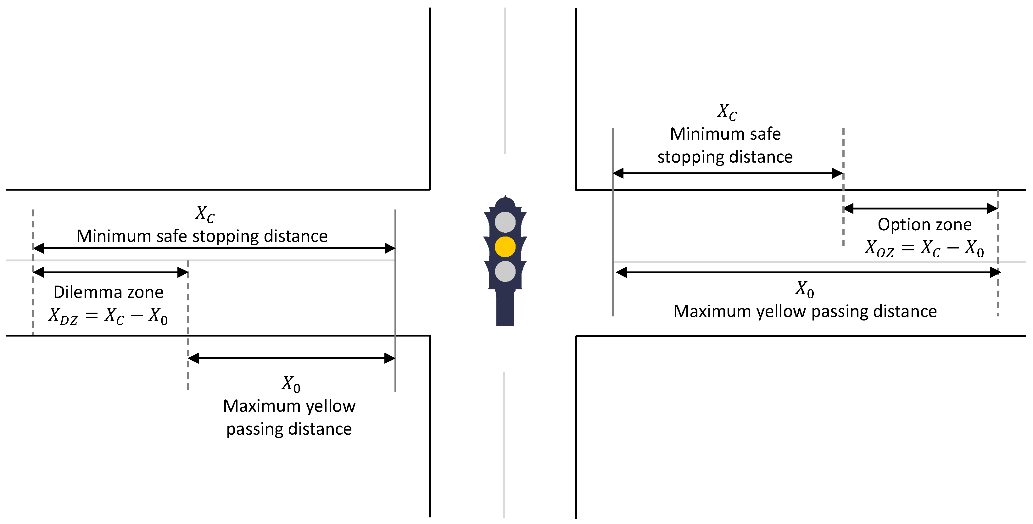
2.1. Motivation Scenario
- Option Zone: The vehicle is far enough from the traffic light that the ADS can confidently choose to stop safely or proceed through the intersection.
- Dilemma Zone: The vehicle is too close to the traffic light to stop safely, but too far to clear the intersection before the light turns red, increasing the risk of entering the intersection during a red signal.
- : the minimum distance from the stop line required for a safe stop;
- : the maximum distance from the stop line within which the vehicle can safely cross the intersection before the amber phase ends.
2.2. Legal Considerations for Autonomous Vehicles at Traffic Lights
2.2.1. Continental Europe: Harmonization Under the Vienna Convention
2.2.2. United Kingdom: Domestic Law Framework
2.2.3. Ireland: EU-Aligned Regulation with Vienna Convention Basis
2.2.4. Regulations on Stop Lines at Traffic Lights
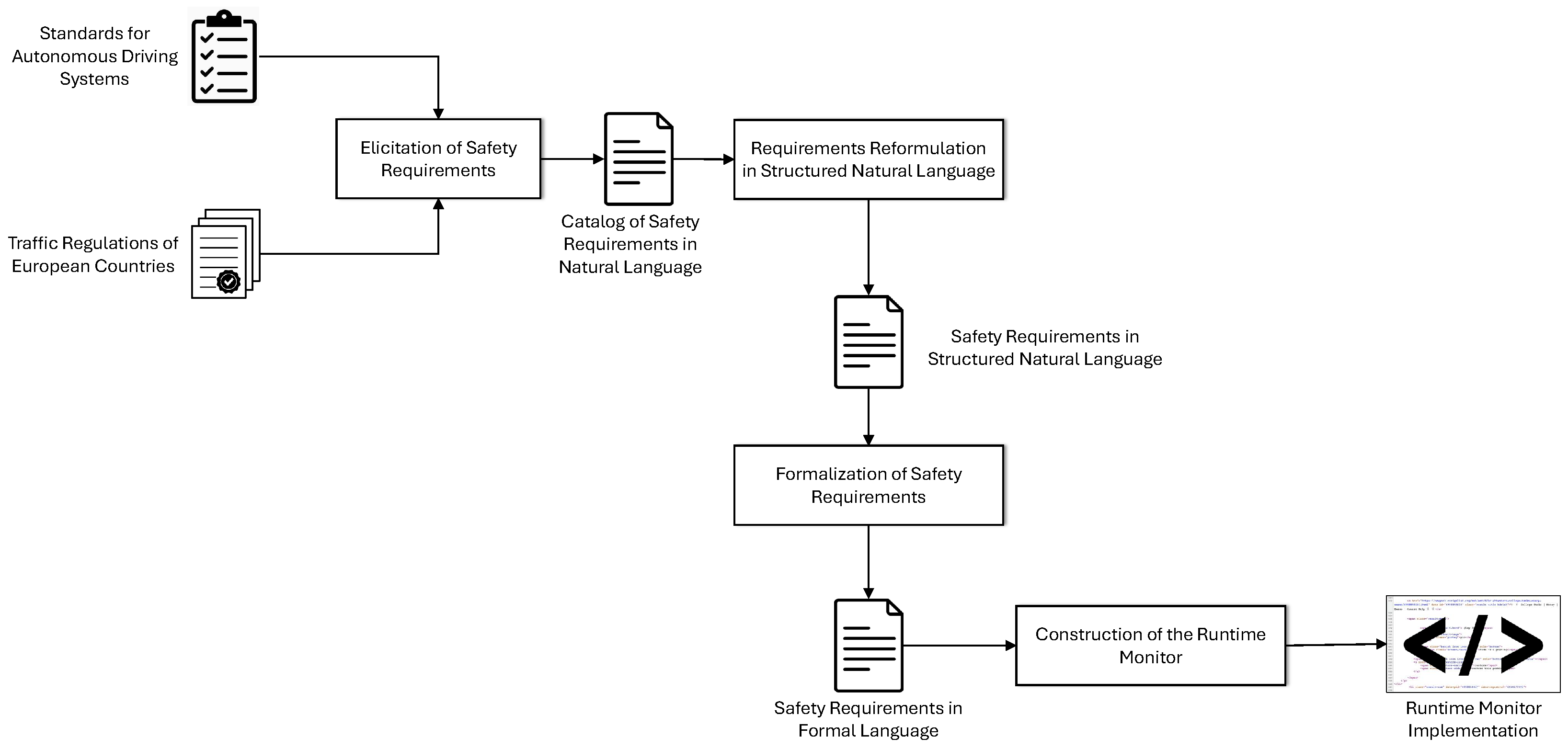
2.3. Method for Constructing Runtime Monitors for ADSs Based on Regulations and Standards
- Elicitation of safety requirements from domain-specific standards and legal regulations;
- Reformulation of safety requirements in a structured natural language;
- Translation of safety requirements in a formal language amenable to runtime monitoring;
- Design of the runtime monitors.
2.3.1. Elicitation of Safety Requirements
2.3.2. Reformulation of Safety Requirements in Structured Natural Language
- Requirements are always described in the active form;
- Requirements are always written as complete sentences;
- Requirements express processes or activities with the help of process verbs;
- Exactly one requirement is formulated for each process verb.
2.3.3. Formalization of Safety Requirements
2.3.4. Design of the Runtime Monitor
2.4. Integrated Safety Architecture for the Runtime Monitoring of ADS Behavior at Traffic Lights
- Fully Autonomous Driving System: Provides the nominal functionality of the ADS;
- Manual Driving System: Enables remote manual control of the autonomous vehicle;
- Emergency Braking System: Activates the emergency brakes in response to critical warnings from the runtime monitor, serving as a fail-safe mechanism (cf. [61]).
- Data Acquisition: LiDAR and camera sensors, mounted on the vehicle’s roof, continuously collect spatial and visual data from the environment.
- Calibration: The coordinate systems of the sensors are calibrated to enable accurate alignment of LiDAR and camera data.
- Point Cloud Projection: LiDAR point clouds are projected onto the camera’s image plane using the calibration parameters, establishing spatial correspondence between the two sensor datasets.
- Feature Extraction: Traffic lights are identified within the camera image, providing target features for mapping.
- Data Linking: Projected LiDAR points are matched with detected traffic lights in the camera image to ensure accurate alignment between modalities.
- Depth Estimation: LiDAR-derived depth information is used to estimate the distance to the identified traffic lights, yielding a fused, range-aware interpretation of the scene.
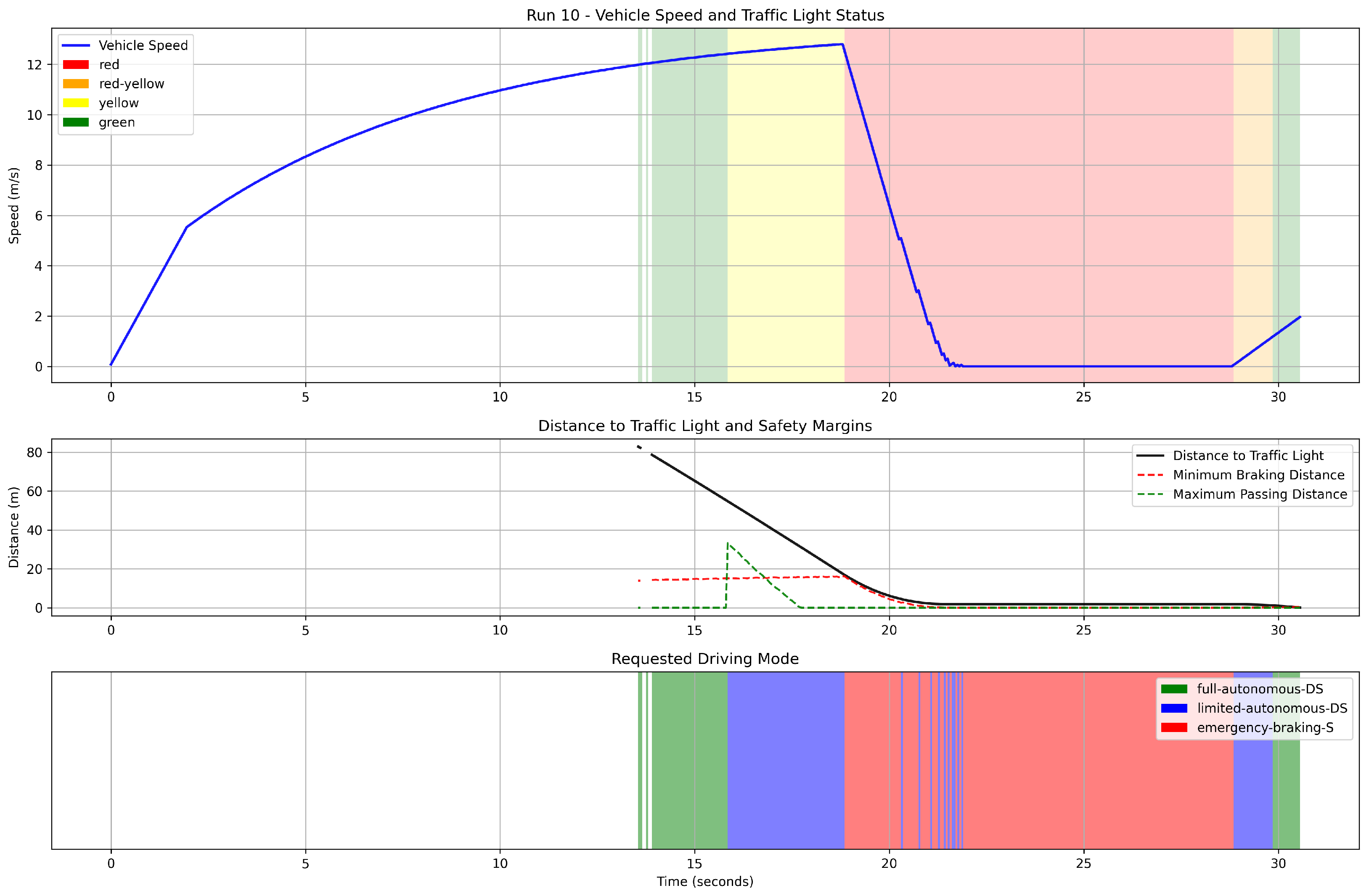
- The vehicle is sufficiently far from the traffic light, allowing the ADS to initiate a smooth braking maneuver in response to a red signal (cf. Equation (1)).
- The vehicle is within the dilemma zone during an amber signal—i.e., it is too close to stop safely yet too far to pass before the signal turns red—requiring a transition to a fail-safe mode (cf. Equation (2)).
- The vehicle is close enough to the intersection during the amber phase to proceed safely before the signal changes to red, and autonomous driving can continue uninterrupted (cf. Equation (3)).
3. Evaluation
3.1. Choice of Evaluation Criteria
- Effectiveness in Safety Assurance: This criterion assesses the runtime monitor’s capability to detect and respond to safety-critical events at traffic lights. It includes evaluating how accurately the monitor identifies violations of safety requirements—such as failure to stop at a red light or inappropriate behavior in the dilemma zone—and how effectively it ensures compliance during various traffic light transitions.
- Robustness and Reliability: Robustness pertains to the monitor’s resilience in diverse and potentially adverse traffic scenarios, including sensor noise, environmental variability, and partial system failures. Reliability refers to the monitor’s consistent performance over time in verifying safety requirements, minimizing false positives (false alarms) and false negatives (missed detections), and maintaining dependable behavior across repeated evaluations.
- Compliance with Ethical and Legal Standards: This criterion examines the monitor’s alignment with established legal regulations and industry standards governing AV safety. It also considers the extent to which the monitor upholds ethical principles, including transparency, accountability, and fairness, thereby supporting public trust and regulatory approval.
- Integration with ADS architecture: This criterion evaluates the ease and effectiveness with which the runtime monitor integrates into the broader autonomous driving architecture. It includes assessing interoperability with other subsystems, compatibility with communication protocols and data exchange formats, and the ability to coordinate real-time responses to safety violations with other system components.
- User Interface and Interaction Design: The usability of the runtime monitor is determined by the clarity and responsiveness of its user interface. This includes evaluating how effectively the system presents visual alerts, status indicators, and control mechanisms to convey critical safety information and support timely human intervention when necessary.
3.1.1. Effectiveness in Safety Assurance
3.1.2. Robustness
3.1.3. Integration with ADS Architectures
3.2. Evaluation Setup
3.3. Experiments Setup and Results
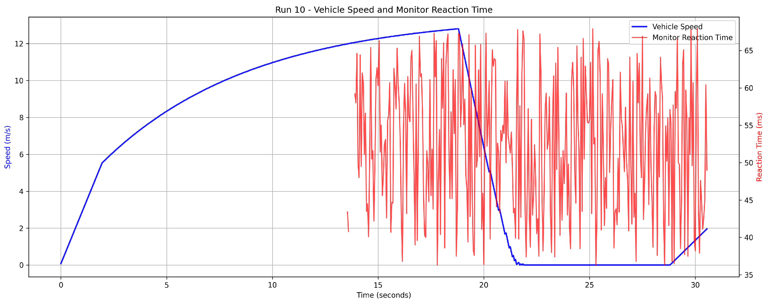
3.3.1. Effectiveness in Safety Assurance
- EQ1:
- Can the runtime monitor reliably detect and respond to traffic lights at varying vehicle speeds, and is the reaction time within acceptable bounds for safe autonomous driving?
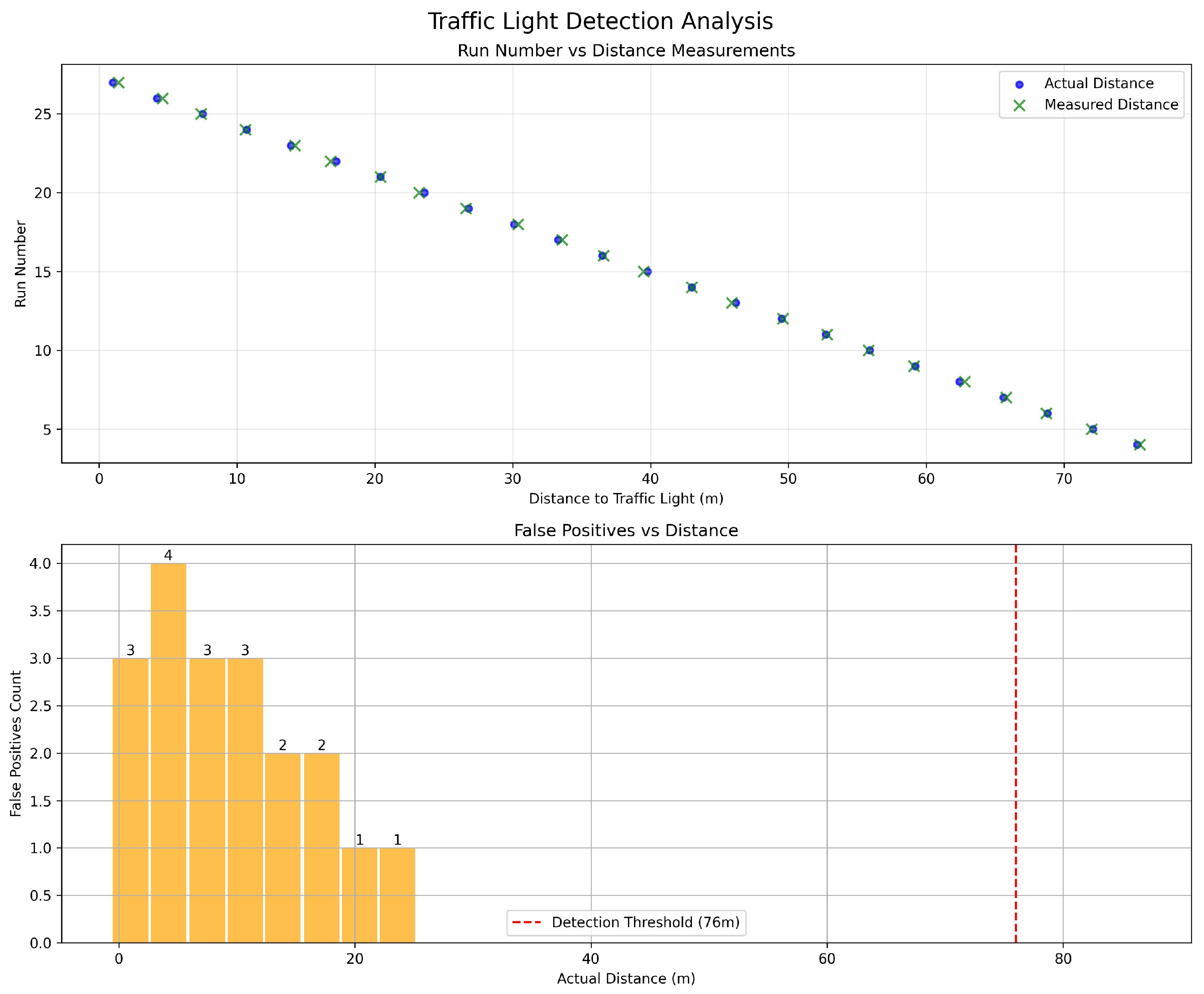
3.3.2. Robustness
- EQ2:
- Can the runtime monitor accurately identify the relevant traffic light while ignoring irrelevant ones at various distances, ensuring reliable decision-making in complex environments?
4. Discussion of Results
4.1. Effectiveness in Safety Assurance
4.2. Robustness
- At 20–25 m, 1–2 irrelevant signals were incorrectly classified as relevant,
- At 10–20 m, 2–3 irrelevant signals were misclassified,
- Below 10 m, 3–4 irrelevant signals were consistently misclassified.
5. Conclusions and Future Work
Author Contributions
Funding
Data Availability Statement
Conflicts of Interest
Abbreviations
| ACC | Adaptive Cruise Control |
| ADAS | Advanced Driving Assistance System |
| ADS | Autonomous Driving System |
| ABS | Anti-lock Braking System |
| AV | Autonomous Vehicle |
| CAS | Collision Avoidance System |
| DDT | Dynamic Driving Task |
| ESC | Electronic Stability Control |
| FuSa | Functional Safety |
| GNSS | Global Navigation Satellite System |
| HIL | Hardware-in-the-Loop |
| LTL | Linear Temporal Logic |
| ODD | Operational Design Domain |
| ROS | Robot Operating System |
| RSA | Road Safety Authority |
| RTSR | Road Traffic (Signs) Regulations in Ireland |
| SOTIF | Safety Of The Intended Functionality |
| StVO | Strassenverkehrs-Ordnung (German road traffic regulations) |
| TSM | Traffic Signs Manual in UK and Ireland |
| TSRGD | Traffic Signs Regulations and General Directions in the UK |
| WSL | Windows Subsystem for Linux |
| YOLO | You Only Look Once |
References
- Vijayenthiran, V. Waymo’s Self-Driving Taxis Will Cover 100 Square Miles of Phoenix. 2018. Available online: https://www.motorauthority.com/news/1116003_cadillac-xt4-will-add-super-cruise-eventually (accessed on 28 May 2025).
- Abdel-Aty, M.; Ding, S. A matched case-control analysis of autonomous vs. human driven vehicle accidents. Nat. Commun. 2024, 15, 4931. [Google Scholar] [CrossRef] [PubMed]
- Ahangarnejad, A.H.; Radmehr, A.; Ahmadian, M. A review of vehicle active safety control methods—From anti-lock brakes to semi-autonomy. J. Vib. Control 2021, 27, 1683–1712. [Google Scholar] [CrossRef]
- Sun, Z.; Bebis, G.; Miller, R. On-road vehicle detection: A review. IEEE Trans. Pattern Anal. Mach. Intell. 2006, 28, 694–711. [Google Scholar] [PubMed]
- Zang, S.; Ding, M.; Smith, D.; Tyler, P.; Rakotoarivelo, T.; Kaafar, M.A. The impact of adverse weather conditions on autonomous vehicles: How rain, snow, fog, and hail affect the performance of a self-driving car. IEEE Vehicular Technol. Mag. 2019, 14, 103–111. [Google Scholar] [CrossRef]
- Vargas, J.; Alsweiss, S.; Toker, O.; Razdan, R.; Santos, J. An Overview of Autonomous Vehicles Sensors and Their Vulnerability to Weather Conditions. Sensors 2021, 21, 5397. [Google Scholar] [CrossRef]
- Brummelen, J.V.; O’Brien, M.; Gruyer, D.; Najjaran, H. Autonomous vehicle perception: The technology of today and tomorrow. Transp. Res. Part C 2018, 89, 384–406. [Google Scholar] [CrossRef]
- Radecki, P.; Campbell, M.; Matzen, K. All weather perception: Joint data association, tracking, and classification for autonomous ground vehicles. arXiV 2016, arXiv:1605.02196. [Google Scholar]
- Filgueira, A.; González-Jorge, H.; Lagüela, S.; Díaz-Vilariño, L.; Arias, P. Quantifying the influence of rain in LiDAR performance. Measurement 2017, 95, 143–148. [Google Scholar] [CrossRef]
- Li, Y.; Wang, H.; Wang, W.; Xing, L.; Liu, S.; Wei, X. Evaluation of the Impacts of Cooperative Adaptive Cruise Control on Reducing Rear-End Collision Risks on Freeways. Accid. Anal. Prev. 2017, 98, 87–95. [Google Scholar] [CrossRef]
- Adewale, A.; Lee, C. Prediction of car-following behavior of autonomous vehicle and human-driven vehicle based on drivers’ memory and cooperation with lead vehicle. Transp. Res. Rec. 2023, 2678, 248–266. [Google Scholar] [CrossRef]
- Li, Y.; Wu, D.; Lee, J.; Yang, M.; Shi, Y. Analysis of the transition condition of rear-end collisions using time-to-collision index and vehicle trajectory data. Accid. Anal. Prev. 2020, 144, 105676. [Google Scholar] [CrossRef] [PubMed]
- SAE J3016:2021; Taxonomy and Definitions for Terms Related to Driving Automation Systems for On-Road Motor Vehicles. SAE International: Warrendale, PA, USA, 2021; Norm, Issued January 2014, Revised April 2021. [CrossRef]
- ISO 26262:2018; Road Vehicles—Functional Safety. ISO: Geneva, Switzerland, 2018; Norm, Issued November 2011, Revised December 2018.
- ISO 21448:2022; Road Vehicles—Safety of the Intended Functionality. ISO: Geneva, Switzerland, 2022; Norm, Issued January 2019, Revised June 2022.
- Levin, M.W.; Boyles, S.D. Intersection Auctions and Reservation-Based Control in Dynamic Traffic Assignment. Transp. Res. Rec. 2019, 2497, 35–44. [Google Scholar] [CrossRef]
- Haris, M.; Hou, J. Obstacle Detection and Safely Navigate the Autonomous Vehicle from Unexpected Obstacles on the Driving Lane. Sensors 2020, 20, 4719. [Google Scholar] [CrossRef] [PubMed]
- Endsley, M.R. Toward a theory of situation awareness in dynamic systems. Hum. Factors 1995, 37, 32–64. [Google Scholar] [CrossRef]
- Zhou, D.; Ma, Z.; Zhang, X.; Sun, J. Autonomous vehicles’ intended cooperative motion planning for unprotected turning at intersections. IET Intell. Transp. Syst. 2020, 16, 1058–1073. [Google Scholar] [CrossRef]
- Alhajyaseen, W.K.M.; Asano, M.; Nakamura, H.; Tan, D.M. Stochastic approach for modeling the effects of intersection geometry on turning vehicle paths. Transp. Res. Part C Emerg. Technol. 2013, 32, 179–192. [Google Scholar] [CrossRef]
- Noh, S. Decision-Making Framework for Autonomous Driving at Road Intersections: Safeguarding Against Collision, Overly Conservative Behavior, and Violation Vehicles. IEEE Trans. Ind. Electron. 2019, 66, 3275–3286. [Google Scholar] [CrossRef]
- Watanabe, K.; Kang, E.; Lin, C.W.; Shiraishi, S. Runtime monitoring for safety of intelligent vehicles. In Proceedings of the 55th Annual Design Automation Conference (DAC ’18), New York, NY, USA, 24–29 June 2018. [Google Scholar] [CrossRef]
- Donzé, A. Breach, A Toolbox for Verification and Parameter Synthesis of Hybrid Systems. In Proceedings of the Computer Aided Verification (CAV ’10); Touili, T., Cook, B., Jackson, P., Eds.; Springer: Berlin/Heidelberg, Germany, 2010; pp. 167–170. [Google Scholar]
- Harper, C.; Chance, G.; Ghobrial, A.; Alam, S.; Pipe, T.; Eder, K. Safety Validation of Autonomous Vehicles Using Assertion-Based Oracles. Preprint. Available online: https://arxiv.org/abs/2111.04611 (accessed on 22 April 2025).
- Grundt, D.; Köhne, A.; Saxena, I.; Stemmer, R.; Westphal, B.; Möhlmann, E. Towards Runtime Monitoring of Complex System Requirements for Autonomous Driving Functions. Electron. Proc. Theor. Comput. Sci. 2022, 371, 53–61. [Google Scholar] [CrossRef]
- Balakrishnan, A.; Deshmukh, J.; Hoxha, B.; Yamaguchi, T.; Fainekos, G. PerceMon: Online Monitoring for Perception Systems. In Proceedings of the 21st International Conference on Runtime Verification (RV 2021); Feng, L., Fisman, D., Eds.; Springer: Cham, Switzerland, 2021; pp. 297–308. [Google Scholar] [CrossRef]
- Antonante, P.; Nilsen, H.G.; Carlone, L. Monitoring of perception systems: Deterministic, probabilistic, and learning-based fault detection and identification. Artif. Intell. Spec. Issue Risk-Aware Auton. 2023, 325, 103998. [Google Scholar] [CrossRef]
- Rong, G.; Shin, B.H.; Tabatabaee, H.; Lu, Q.; Lemke, S.; Možeiko, M.; Boise, E.; Uhm, G.; Gerow, M.; Mehta, S.; et al. LGSVL Simulator: A High Fidelity Simulator for Autonomous Driving. arXiv 2020, arXiv:2005.03778. [Google Scholar]
- Zhang, Y.; Xu, S.; Chen, H.; Aslam Bhatt, U.; Huang, M. Context-aware environment online monitoring for safety autonomous vehicle systems: An automata-theoretic approach. J. Cloud Comput. 2024, 13, 6. [Google Scholar] [CrossRef]
- Yu, W.; Zhao, C.; Wang, H.; Liu, J.; Ma, X.; Yang, Y.; Li, J.; Wang, W.; Hu, X.; Zhao, D. Online legal driving behavior monitoring for self-driving vehicles. Nat. Commun. 2024, 15, 408. [Google Scholar] [CrossRef] [PubMed]
- Mehdipour, N.; Althoff, M.; Tebbens, R.D.; Belta, C. Formal methods to comply with rules of the road in autonomous driving: State of the art and grand challenges. Automatica 2023, 152, 110692. [Google Scholar] [CrossRef]
- Huang, Z.; Li, B.; Du, D.; Li, Q. A Model Checking Based Approach to Detect Safety-Critical Adversarial Examples on Autonomous Driving Systems. In Proceedings of the Theoretical Aspects of Computing—ICTAC 2022; Seidl, H., Liu, Z., Pasareanu, C.S., Eds.; Springer: Cham, Switzerland, 2022; pp. 238–254. [Google Scholar] [CrossRef]
- Arfvidsson, K.M.; Jiang, F.J.; Johansson, K.H.; Mårtensson, J. Ensuring Safety at Intelligent Intersections: Temporal Logic Meets Reachability Analysis. In Proceedings of the 2024 IEEE Intelligent Vehicles Symposium (IV), Jeju Island, Republic of Korea, 2–5 June 2024; pp. 292–298. [Google Scholar] [CrossRef]
- Wu, S.; Amenta, N.; Zhou, J.; Papais, S.; Kelly, J. aUToLights: A Robust Multi-Camera Traffic Light Detection and Tracking System. In Proceedings of the 2023 20th Conference on Robots and Vision (CRV), Montreal, QC, Canada, 6–8 June 2023; pp. 89–96. [Google Scholar] [CrossRef]
- Rahman, M.; Islam, F.; Ball, J.E.; Goodin, C. Traffic light recognition and V2I communications of an autonomous vehicle with the traffic light for effective intersection navigation using YOLOv8 and MAVS simulation. In Proceedings of the Autonomous Systems: Sensors, Processing, and Security for Ground, Air, Sea, and Space Vehicles and Infrastructure; Dudzik, M.C., Jameson, S.M., Axenson, T.J., Eds.; International Society for Optics and Photonics, SPIE: Bellingham, WA, USA, 2024; Volume 13052. [Google Scholar] [CrossRef]
- Kumar, G.A.; Lee, J.H.; Hwang, J.; Park, J.; Youn, S.H.; Kwon, S. LiDAR and Camera Fusion Approach for Object Distance Estimation in Self-Driving Vehicles. Symmetry 2020, 12, 324. [Google Scholar] [CrossRef]
- Gao, F.; Luo, C.; Shi, F.; Chen, X.; Gao, Z.; Zhao, R. Online Safety Verification of Autonomous Driving Decision-Making Based on Dynamic Reachability Analysis. IEEE Access 2023, 11, 93293–93309. [Google Scholar] [CrossRef]
- Navarro-Espinoza, A.; Lopez-Bonilla, O.; García-Guerrero, E.; Tlelo-Cuautle, E.; Lopez-Mancilla, D.; Hernández-Mejía, C.; Gonzalez, E.I. Traffic Flow Prediction for Smart Traffic Lights Using Machine Learning Algorithms. Technologies 2022, 10, 5. [Google Scholar] [CrossRef]
- Ugirumurera, J.; Severino, J.; Bensen, E.; Wang, Q.; Macfarlane, J. A Machine Learning Method for Predicting Traffic Signal Timing from Probe Vehicle Data. arXiv 2023. [Google Scholar] [CrossRef]
- Smith, S. Integration of Autonomous Vehicles with Adaptive Signal Control to Enhance Mobility; Technical Report; Carnegie Mellon University: Pittsburgh, PA, USA, 2019. [Google Scholar]
- Maadi, S.; Stein, S.; Hong, J.; Murray-Smith, R. Real-Time Adaptive Traffic Signal Control in a Connected and Automated Vehicle Environment: Optimisation of Signal Planning with Reinforcement Learning under Vehicle Speed Guidance. Sensors 2022, 22, 7501. [Google Scholar] [CrossRef]
- Dong, H.; Zhuang, W.; Wu, G.; Li, Z.; Yin, G.; Song, Z. Overtaking-Enabled Eco-Approach Control at Signalized Intersections for Connected and Automated Vehicles. Trans. Intell. Transport. Syst. 2024, 25, 4527–4539. [Google Scholar] [CrossRef]
- Chang, M.; Messer, C.J.; Santiago, A.J. Timing Traffic Signal Change Intervals based on Driver Behavior. Transp. Res. Rec. 1985. [Google Scholar]
- Zhang, Y.; Fu, C.; Hu, L. Yellow light dilemma zone researches: A review. J. Traffic Transp. Eng. (Engl. Ed.) 2014, 1, 338–352. [Google Scholar] [CrossRef]
- 20. Convention on Road Signs and Signals; International Treaty; UNECE: Vienna, Austria, 1968.
- Bundestag. Gesetz zur Änderung des Straßenverkehrsgesetzes und des Pflichtversicherungsgesetzes—Gesetz zum autonomen Fahren. Bundesgesetzblatt Jahrgang 2021 Teil I Nr. 48, ausgegeben zu Bonn am 27. Juli 2021. 2021. National Law. Available online: https://www.bgbl.de/xaver/bgbl/start.xav?startbk=Bundesanzeiger_BGBl&start=//*%5b@attr_id=%27bgbl121s3108.pdf%27%5d#/switch/tocPane?_ts=1749380516316 (accessed on 22 April 2025).
- The Traffic Signs Regulations and General Directions 2016; National Law; UK Statutory Instruments: London, UK, 2016.
- Automated and Electric Vehicles Act 2018; National Law; UK Public General Acts: London, UK, 2018.
- Automated Vehicles Act 2024; National Law; UK Public General Acts: London, UK, 2024.
- Traffic Signs Manual—Chapter 9: Traffic Signals; National Law; Irish Department of Transport: Dublin, Ireland, 2024.
- Bundestag. Straßenverkehrs-Ordnung. Verordnung vom 06.03.2013 (BGBl. I S. 367), in Kraft Getreten am 01.04.2013 Zuletzt Geändert Durch Gesetz vom 11.12.2024 (BGBl. I S. 411) m.W.v. 01.01.2025. 2024. National Law. Available online: https://www.stvo.de/strassenverkehrsordnung/ (accessed on 22 April 2025).
- Richtlinienfür Lichtsignalanlagen (RiLSA)—Lichtzeichenanlagen für den Straßenverkehr. FGSV Verlag. Guideline. Available online: https://www.fgsv-verlag.de/pub/media/pdf/321.i.pdf (accessed on 22 April 2025).
- Versionsconsolidées de 2023 des 9 Parties de l’Instruction Interministérielle sur la Signalisation Routière (IISR). Journal of Official de la République Française (JORF). 2023. Instructions. Available online: https://equipementsdelaroute.cerema.fr/versions-consolidees-de-2023-des-9-parties-de-l-a528.html (accessed on 22 April 2025).
- Traffic Signs Manual—Chapter 6: Traffic Control; National Law; UK Department for Transport: London, UK, 2019.
- Road Traffic (Signs) Regulations; Statute; Irish Statutory Instruments: Dublin, Ireland, 2024.
- SOPHISTen.MASTeR—Schablonen für alle Fälle (Engl.: MASTeR—Requirements Patterns for All Use Cases). Brochure. 2024. Available online: https://www.sophistgroup.de/fileadmin/user_upload/Bilder_zu_Seiten/Publikationen/Wissen_for_free/MASTeR-Broschuere_Int/MASTeR_Broschuere_6-Auflage_31-07-2024_AvP_V4.pdf (accessed on 22 March 2025).
- Baier, C.; Katoen, J.P. Principles of Model Checking; MIT Press: Cambridge, MA, USA, 2008. [Google Scholar]
- Hegerhorst, T.; Vorwald, A.; Flormann, M.; Zhang, M.; Henze, R.; Rausch, A. VanAssist—Integriertes Sicherheitskonzept für Automatisierte Kleintransporter in der Paketlogistik (Engl.: VanAssist: Integrated safety concept for automated transport vans in parcel logistics). In Proceedings of the ACIMobility Summit, Braunschweig, Germany, 21–22 September 2021; pp. 1–12. [Google Scholar]
- Aniculaesei, A.; Grieser, J.; Rausch, A.; Rehfeldt, K.; Warnecke, T. Graceful Degradation of Decision and Control Responsibility for Autonomous Systems based on Dependability Cages. In Proceedings of the 5th International Symposium on Future Active Safety Technology Toward Zero Accidents, Blacksburg, VA, USA, 9–11 September 2019. [Google Scholar]
- Aniculaesei, A.; Aslam, I.; Bamal, D.; Helsch, F.; Vorwald, A.; Zhang, M.; Rausch, A. Connected Dependability Cage Approach for Safe Automated Driving. In Proceedings of the 23rd International Stuttgart Symposium; Kulzer, A.C., Reuss, H.C., Wagner, A., Eds.; Springer: Wiesbaden, Germany, 2023; pp. 3–21. [Google Scholar]
- Aslam, I.; Aniculaesei, A.; Buragohain, A.; Zhang, M.; Bamal, D.; Rausch, A. Runtime Safety Assurance of Autonomous Last-Mile Delivery Vehicles in Urban-like Environment. In Proceedings of the 2024 Stuttgart International Symposium. SAE International, Stuttgart, Germany, 2–3 July 2024. [Google Scholar] [CrossRef]
- Driveblocks. Fast Reaction Times: Why End-to-End Latency Matters in Autonomous Driving. 2022. Available online: https://www.driveblocks.ai/news/2022-11-28/fast-reaction-times-why-end-to-end-latency-matters-in-autonomous-driving (accessed on 28 May 2025).
- ISO 26262; Road Vehicles—Functional Safety. International Organization for Standardization: Geneva, Switzerland, 2018. Available online: https://www.iso.org/standard/68383.html (accessed on 22 March 2025).
- AVL List GmbH. AVL Dynamic Ground Truth System. 2024. Available online: https://www.avl.com/en/testing-solutions/automated-and-connected-mobility-testing/avl-dynamic-ground-truth-system (accessed on 22 May 2025).
- Wu, J.; Song, Z.; Lv, C. Deep Reinforcement Learning-Based Energy-Efficient Decision-Making for Autonomous Electric Vehicle in Dynamic Traffic Environments. IEEE Trans. Intell. Transp. Syst. 2023, 1, 875–887. [Google Scholar] [CrossRef]
- Meng, X.; Cassandras, C. Eco-Driving of Autonomous Vehicles for Nonstop Crossing of Signalized Intersections. IEEE Trans. Autom. Sci. Eng. 2022, 19, 320–331. [Google Scholar] [CrossRef]


| Phase | Position | Meaning |
|---|---|---|
| Red | At intersection | Vehicle may not proceed beyond the stop line or enter the intersection. |
| Red and Amber | At intersection | The signal is about to change, but the red light rules apply. |
| Amber | At intersection, level crossing, swing bridge, airport, fire station or ferry terminal | Vehicle may not pass the stop line or enter the intersection, unless it cannot safely stop when the light shows. |
| Green | At intersection, entrance to tunnel or bridge | Vehicle may proceed, unless it is unable to clear the intersection before the next phase change. |
| Phase | Meaning |
|---|---|
| Red | Vehicle must not proceed beyond the stop line. |
| Red and Amber | Impending change to green, but the same prohibition as the red signal applies. |
| Amber | Stop, unless too close to the stop line to do so safely. |
| Green | Vehicle may proceed beyond the stop line and proceed straight on, to the left, or to the right. |
| Phase | Meaning |
|---|---|
| Red | Vehicles must not proceed past the primary traffic signal or the associated stop line. |
| Amber | Vehicles must not pass the signal or stop line, unless they cannot safely stop in time. |
| Green | Vehicles may proceed with caution. |
| Jurisdiction | Stop Line Required | Typical Distance from Signal Head | Governing Regulation |
|---|---|---|---|
| Continental Europe | Yes | 1.0–2.5 m | Vienna Convention [45] and Laws of National States, e.g., Germany [51,52] and France [53]. |
| United Kingdom | Yes | 1.5–2.5 m | TSRGD 2016 [47] and TSM 2019 [54]. |
| Ireland | Yes | 1.0–2.0 m | Irish TSM [50] and RTSR [55]. |
| Requirement ID | Requirement Text |
|---|---|
| RSR1 | The ADS recognizes a red or amber traffic light and calculates the distance to the stop line. As soon as it reaches the minimum safe braking distance, the ADS initiates a gentle braking maneuver to stop the vehicle safely without crossing the stop line. |
| RSR2 | The ADS recognizes when the traffic light changes from green to amber and finds itself in the dilemma zone. In this critical situation, the ADS initiates emergency braking to stop the vehicle safely and avoid crossing the stop line. |
| RSR3 | The ADS recognizes that the traffic light changes from green to amber and is within the maximum yellow crossing distance. In this situation, the ADS drives further and the vehicle safely crosses the intersection. |
| Requirement ID | Requirement Text |
|---|---|
| RSR1 | The ADS shall initiate a progressive braking maneuver, if the traffic light is red or amber and the distance to the stop line is equal to the minimum safe braking distance. |
| RSR2 | The ADS shall initiate an emergency braking maneuver, if the traffic light changes from green to amber and the distance to the stop line is less than the minimum safe braking distance and greater than the maximum yellow passing distance. |
| RSR3 | The ADS shall drive further, if the traffic light changes from green to amber and the distance to the stop line is less than or equal to the maximum yellow passing distance. |
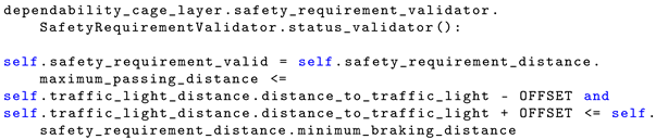
| Predicate in LTL Safety Requirement | Implementation in Runtime Monitor |
|---|---|
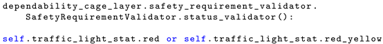 | |
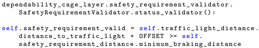 | |
| FullAutonomousDriving: ProgressiveBraking | 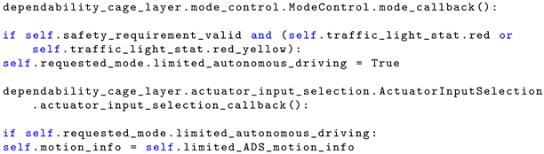 |
| Predicate in LTL Safety Requirement | Implementation in Runtime Monitor |
|---|---|
 | |
 | |
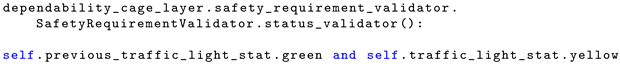
| EmergencyBraking | 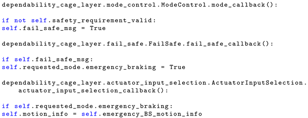 |
| Predicate in LTL Safety Requirement | Implementation in Runtime Monitor |
|---|---|
 | |
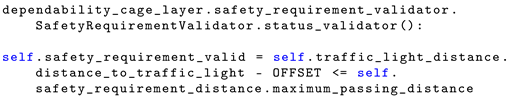 | |
| FullAutonomousDriving: Drive |  |
Disclaimer/Publisher’s Note: The statements, opinions and data contained in all publications are solely those of the individual author(s) and contributor(s) and not of MDPI and/or the editor(s). MDPI and/or the editor(s) disclaim responsibility for any injury to people or property resulting from any ideas, methods, instructions or products referred to in the content. |
© 2025 by the authors. Licensee MDPI, Basel, Switzerland. This article is an open access article distributed under the terms and conditions of the Creative Commons Attribution (CC BY) license (https://creativecommons.org/licenses/by/4.0/).
Share and Cite
Aniculaesei, A.; Elhajji, Y. Runtime Monitoring Approach to Safeguard Behavior of Autonomous Vehicles at Traffic Lights. Electronics 2025, 14, 2366. https://doi.org/10.3390/electronics14122366
Aniculaesei A, Elhajji Y. Runtime Monitoring Approach to Safeguard Behavior of Autonomous Vehicles at Traffic Lights. Electronics. 2025; 14(12):2366. https://doi.org/10.3390/electronics14122366
Chicago/Turabian StyleAniculaesei, Adina, and Yousri Elhajji. 2025. "Runtime Monitoring Approach to Safeguard Behavior of Autonomous Vehicles at Traffic Lights" Electronics 14, no. 12: 2366. https://doi.org/10.3390/electronics14122366
APA StyleAniculaesei, A., & Elhajji, Y. (2025). Runtime Monitoring Approach to Safeguard Behavior of Autonomous Vehicles at Traffic Lights. Electronics, 14(12), 2366. https://doi.org/10.3390/electronics14122366