Abstract
Given the problems of uneven distribution, strong time variability of ground service demands, and low utilization rate of on-board resources in Low-Earth-Orbit (LEO) satellite communication systems, how to efficiently utilize limited beam resources to flexibly and dynamically serve ground users has become a research hotspot. This paper studies the dynamic resource allocation and interference suppression strategies for beam hopping satellite communication systems. Specifically, in the full-frequency-reuse scenario, we adopt spatial isolation techniques to avoid co-channel interference between beams and construct a multi-objective optimization problem by introducing weight coefficients, aiming to maximize user satisfaction and minimize transmission delay simultaneously. We model this optimization problem as a Markov decision process and apply a value decomposition network (VDN) algorithm based on cooperative multi-agent reinforcement learning (MARL-VDN) to reduce computational complexity. In this algorithm framework, each beam acts as an agent, making independent decisions on hopping patterns and power allocation strategies, while achieving multi-agent cooperative optimization through sharing global states and joint reward mechanisms. Simulation results show that the applied algorithm can effectively enhance user satisfaction, reduce delay, and maintain high resource utilization in dynamic service demand scenarios. Additionally, the offline-trained MARL-VDN model can be deployed on LEO satellites in a distributed mode to achieve real-time on-board resource allocation on demand.
1. Introduction
With the rapid development of communication technologies, users’ demands for high-quality and full-domain coverage communication services are growing increasingly. Although terrestrial communication networks are continuously improving, coverage blind spots still exist in remote areas and special scenarios, which makes satellite communication systems an indispensable supplementary solution [1,2]. Satellite communication systems possess advantages such as wide coverage and strong communication capabilities, which are highly compatible with the development needs of communication networks in the 6G era [3]. In the field of satellite communication, compared with Geostationary Orbit satellites, Low-Earth-Orbit (LEO) satellites have become a research hotspot due to their shorter round-trip delay and lower signal path loss [4]. However, due to the non-uniform spatial distribution of ground users, the time-varying nature of user service requests, and the high-speed movement characteristics of satellites, service demands become dynamically unbalanced in the spatial dimension [5]. Additionally, the resources of LEO satellites are limited by objective factors, such as satellite volume, weight, and energy reserves. Therefore, how to make full use of limited resources to match complex and changeable service demands has become a major challenge faced by power-constrained LEO satellite communication systems [6,7], especially in application scenarios such as sudden events and peak traffic periods, where the rapid change of user demands places higher requirements on the intelligence and flexibility of resource allocation mechanisms.
Multi-beam satellites can generate many beams and improve service quality and system capacity through flexible allocation of beam resources, playing an important role in solving the above problems [8]. However, there are still many difficulties in truly achieving efficient utilization of LEO satellite resources [9]. In power-constrained multi-beam satellite communication systems, traditional static resource allocation schemes struggle to cope with complex and changeable communication demands. To ensure the quality of service for high-data-rate services, it is necessary to introduce beam hopping technology [10]. Traditional fixed resource allocation methods are prone to resource waste and ineffective coverage problems when facing application scenarios with uneven traffic demands. In contrast, beam hopping technology can effectively adapt to the non-uniform distribution characteristics of traffic demands by dynamically adjusting beam pointing, coverage areas, and transmission power, thereby significantly improving resource utilization. For beam hopping optimization problems, traditional iterative algorithms and heuristic algorithms have a lag in real-time response, and simply relying on data-driven methods may lead to optimization difficulties, invalid constraints, and performance degradation. Therefore, it is necessary to explore new optimization methods [11].
To better adapt to the changes in time-varying traffic demand distribution, the authors of [12] designed a beam switching scheme suitable for beam hopping systems in LEO satellites, providing a fundamental framework for addressing the challenges of limited resources and dynamic demands. In [13], the authors propose dividing the satellite coverage area into multiple fine-grained clusters, dynamically serving different clusters based on user demands. This approach not only effectively avoids inter-cluster spectral interference but also enables flexible resource allocation. The authors transform user traffic demands into a Markov Decision Process (MDP) in [14], offering a modeling paradigm for the subsequent processing of traffic demands and decision making in resource allocation. To achieve more efficient beam resource utilization and better communication services, the determinantal point process algorithm is introduced to solve beam hopping problems in [15], accurately allocating resources according to traffic demands and providing a novel algorithmic-level solution for addressing limited beam resources. The authors propose an efficient beam hopping pattern in [16], optimizing the pattern to enhance resource allocation efficiency and overall system performance. The authors of [17] decompose the bivariate optimization problem of power and bandwidth allocation into two univariate sub-problems, effectively solving the joint optimization challenge.
In recent years, reinforcement learning (RL) has emerged as a critical methodology for resource allocation in beam hopping satellite communication systems [11]. In [18], the authors integrate traditional beam hopping optimization with machine learning techniques, using learning algorithms to assist the optimization process. This approach provides a new framework for improving resource utilization efficiency and communication quality, overcoming the limitations of relying solely on traditional algorithms through technological convergence. Building on this, the authors of [19] further advance into the field of deep reinforcement learning, proposing a deep reinforcement learning framework to design beam hopping patterns and applying heuristic algorithms to enhance system capacity. The authors of [20] apply value decomposition network (VDN) learning to the field of multi-agent reinforcement learning (MARL). The authors in [21] introduce a multi-agent reinforcement learning method to optimize beam hopping in multi-beam non-geostationary orbit constellations, marking the application of multi-agent methodologies. In [2], the authors present a multi-agent deep reinforcement learning approach to address dynamic beam pattern and bandwidth allocation in high-throughput beam hopping satellite systems. The authors of [22] employ model-free multi-objective deep reinforcement learning to learn optimal policies through environmental interaction. In [23], the authors combine deep reinforcement learning with genetic algorithms as an auxiliary mechanism to maximize long-term system throughput. The authors propose a parameterized reinforcement learning method in [24], maximizing long-term cumulative rewards by learning a parameterized policy network. The authors in [25] develop a multi-agent deep Q-network algorithm, where agents select optimal strategies based on current network states. Among numerous MARL algorithms, the VDN algorithm has emerged as an effective approach for solving multi-agent cooperative tasks, owing to its unique value decomposition strategy and efficient coordination mechanism.
Based on the research of the above studies, we find that with the increase in the number of service beams, the search space of beam hopping patterns grows exponentially, significantly increasing the complexity of heuristic algorithms [2]. In addition, most reinforcement learning algorithms are deployed on satellites centralized after training, making it impossible to make appropriate resource allocation decisions in real time. To address the above issues, this paper proposes applying a value decomposition network algorithm framework based on cooperative multi-agent reinforcement learning (MARL-VDN) in LEO beam hopping satellite communication systems. Each agent makes decisions about the beam hopping pattern and the power allocation of one beam, allowing agents to achieve global objective optimization while making local decisions. The main contributions of this paper are as follows.
- To solve the problem of uneven ground traffic distribution in LEO beam hopping satellite communication systems, we establish a downlink transmission link model. To fully utilize beam resources, a cooperative MARL-VDN algorithm is applied for joint beam hopping pattern and power allocation decisions, achieving multi-objective optimization of the system and enabling limited on-board resources to dynamically match nonuniform and time-varying traffic demands.
- The optimization algorithm for the joint beam hopping pattern and power allocation needs to make decisions sequentially in multiple time slots. However, traditional optimization methods exhibit high computational complexity, resulting in a long convergence time and failing to meet the real-time requirements. Therefore, this paper employs a cooperative MARL-VDN algorithm framework using the centralized training and decentralized execution (CTDE) paradigm to address sequential decision-making problems. After offline training, the model can be deployed on LEO satellites to achieve real-time beam hopping scheduling.
- In the applied cooperative MARL-VDN algorithm framework, each agent only manages the hopping pattern and power allocation decision for a single beam, thereby reducing both the individual agent’s action space and the overall joint action space across all agents. In addition, agents can continuously optimize their policies through ongoing interaction with the environment to better adapt to changing and complex communication environments.
The rest of this paper is structured as follows. Section 2 first introduces the system model then explores interference suppression strategies and dynamic beam optimization problems in LEO beam hopping satellite communication systems. A cooperative MARL-VDN algorithm framework is applied to solve this problem in Section 3. Section 4 provides the complexity analysis and simulation results, which demonstrate the excellent performance of the MARL-VDN algorithm when it is applied to the LEO beam hopping satellite system. Finally, Section 5 concludes the paper.
Notation: The notations and definitions used in this paper are summarized in Table 1.

Table 1.
System notations.
2. System Model and Problem Formulation
2.1. System Model
A forward link model of the LEO beam hopping satellite system, as depicted in Figure 1, is constructed in this paper. Assume that there are M beam positions within the coverage area of a single LEO satellite. The set of ground beam positions is defined as . The satellite generates K service beams through Time Division Multiple Access to serve users. The set of satellite service beams is defined as , where K represents the maximum number of service beams and . Suppose that each beam has N power level options. The set of transmit powers of each satellite service beam is defined as . A beam hopping period is divided into T time slots, and the beam hopping period is defined as . Due to the uneven distribution of ground users and the time-varying nature of their service requirements, the traffic demands of each beam position are different. To meet the differentiated traffic demands of ground beam positions, the satellite must determine which beam positions are illuminated by service beams. Specifically, the satellite needs to know the beam hopping pattern in time slot t. Assume that each service beam can only illuminate one beam position at any time slot of the beam hopping period. The beam hopping pattern in time slot t is defined as , ,where indicates whether beam position m is illuminated by a service beam in time slot t. Specifically speaking, means beam position m is illuminated by the beam, and means the beam does not illuminate beam position m.
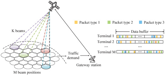
Figure 1.
Forward link model of LEO beam hopping satellite system.
Suppose that the satellite provides corresponding packet buffer queues for each beam position to store the arriving traffic. The newly arrived packet at beam position m in time slot t is defined as . Due to the limited on-board storage space, to reduce memory usage, a queuing delay threshold is set for each packet buffer queue. The queue only stores the packets that arrived within the past time slots, and when the delay of a packet in the queue exceeds this threshold, the packet will be discarded. The packet buffer queues of all beam positions in time slot t are defined as , where represents the packet buffer queue of beam position m in time slot t. Since the current packet queue cannot be known when simulating the satellite-to-ground communication environment, it is assumed that the packet arrivals at each beam position before entering the beam hopping period follow a Poisson distribution (with an arrival rate of ). After entering the beam hopping period, all beam positions generate new service packets with a probability of in each beam hopping time slot, and the newly added packets are stored in the queues of each beam position. Considering the diversity of users’ communication services, the packets arriving at the beam positions are simply divided into three types, and their data amounts are different. The traffic demands of all beam positions in time slot t are defined as , where represents the traffic demand of beam position m in time slot t, meaning the total traffic demands of all users at this beam position within the past time slots. is the data amount corresponding to the packet in the packet queue.
2.2. Channel Model
The forward-path channel coefficient between satellite beam k and beam position m is defined as , which is composed of path transmission loss , satellite antenna transmit gain , ground-end antenna receive gain , and the beam hopping pattern of this beam position in the current time slot. Specifically, the forward-path channel coefficient is expressed as . Therefore, represents the channel coefficient matrix between on-board beams and ground beam positions. The path loss can be calculated as follows:
where the components included in Equation (1) can be defined as follows.
- : Free-space loss, a function of carrier frequency , and the straight-line distance between the satellite and the beam-positioning center.
- : Shadow fading, modeled as a log-normal random variable.
- : Rain attenuation, dependent on rain probability .
- : Multipath fading, characterized by a Rayleigh distribution.
The mathematical expressions for each component can be represented as follows:
where represents the shadow variance, represents the attenuation value with an annual average rain-time percentage of 0.01%, and represents the Rayleigh distribution standard deviation.
In this paper, to ensure efficient utilization of the frequency band and enable each beam to share on-board resources, the communication system employs a full frequency reuse scheme for beam allocation. However, this approach means that there is non-negligible co-channel interference among different service beams at the same time. Therefore, it is necessary to model and analyze beam interference.
The inter-beam interference value mainly depends on the angle between the satellite’s aiming lines to the centers of beam positions m and i.The cause of co-channel interference is the radiation from the antenna side-lobes interfering with co-channel beam positions. The co-channel interference model for LEO satellites is shown in Figure 2. Service beams illuminate beam position m and beam position i at the same time. The geometric angle formed by the satellite’s center to beam position m and its center to beam position i is denoted by . In this scenario, assuming that beam position m is the interfered area, we discuss the co-channel interference that beam position i causes for beam position m. The interference between beam positions in the downlink can be denoted by
where M represents the number of beam positions that share the same frequency as beam position m. is the transmit power of the satellite for beam position i other than beam position m. is the antenna gain from the satellite to the center point of beam position i. d is the signal propagation distance. is the signal wavelength. is the channel attenuation from the satellite to the center point of the interfered beam position m. is the antenna gain of the beam illuminating beam position i concerning the center point of beam position i, and the expression is as follows.
where represents the peak value of the beam gain. and represent the first-order and third-order Bessel functions of the first kind, respectively. represents the antenna efficiency. N represents a constant related to the antenna radiation pattern. represents the angle between the signal emission direction and the pointing direction of the beam center. represents the 3 dB beamwidth. It can be calculated from the trigonometric formula as
where represents the geometric distance from the satellite to the center of beam position m. Similarly, represents the geometric distance from the satellite to the center of beam position i, and the distance between the centers of the two beam positions is d. When the Earth’s radius R and the satellite’s orbital height h are fixed, the magnitudes of and are also fixed, and then the magnitude of the angle is determined by the distance d between the center points of the two beam positions.
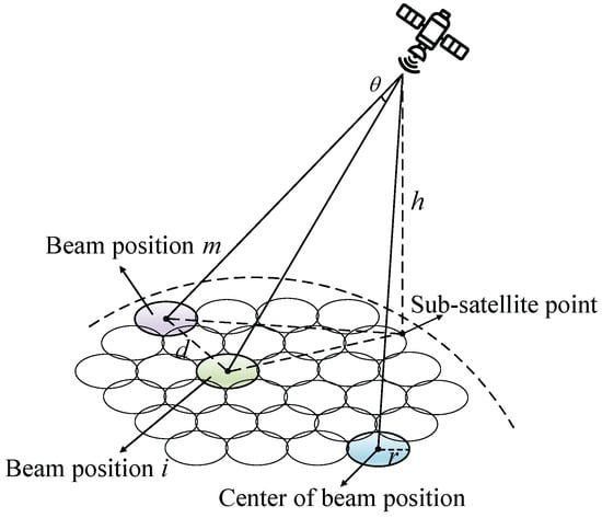
Figure 2.
Co-channel interference in an LEO satellite system.
The Signal-to-Interference-plus-Noise-Ratio (SINR) of beam position m, denoted by , can be expressed as
where is the transmit power of the satellite beam for beam position m. represents the channel coefficient of service beam k illuminating beam position m. represents the total on-board bandwidth. represents the noise power spectral density. is the co-channel interference that co-channel beam position i causes to beam position m. Taking the distance d between the centers of beam position m and beam position i as a variable, the SINR of beam position m is obtained as shown in Figure 3.
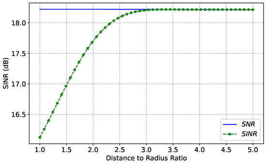
Figure 3.
Influence of the spacing between the centers of simultaneously operating beams on SINR.
According to the Shannon formula, the channel capacity of beam position m in time slot t can be obtained by
If , indicating that beam position m is not illuminated in time slot t, the channel capacity becomes 0. The throughput of beam position m in time slot t can be described as
2.3. Problem Formulation
The total packet delay is defined as , where is the time slot when the packet is completely transmitted, and is the time slot when the packet is generated. The queuing and transmission delays are calculated statistically over the interval from to .
To minimize the traffic delay and improve user satisfaction to the greatest extent, a dynamic beam hopping multi-objective optimization problem is established. The problem can be modeled as
In this optimization problem, we take the beam hopping pattern and the beam transmit power of each time slot as optimization variables. represents the weight coefficient between delay and user satisfaction. Constraint indicates that the number of illuminated beam positions within any time slot is consistent with the maximum number of satellite service beams. restricts the range of the transmit power of a single beam. Similarly, constrains the upper limit of the sum of the transmit powers of all service beams within any time slot. Considering the problem of users’ quality of service, specifies the upper limit of the actual data throughput of the illuminated beam positions. describes the maximum dwell time of data packets through the delay threshold. Due to the limitation of on-board memory size, data packets in the data packet buffer queue that exceed this threshold will be discarded.
The optimization problem in Equation (14) is non-convex and non-linear. Due to the long-term accumulation characteristic of the objective function, the problem is reformulated as a sequential decision-making task to determine the power allocation and beam hopping pattern for each time slot. The traffic data volume of the packet buffer queue for each beam position in the next time slot depends on the traffic data volume of this beam position in the current time slot, the beam hopping pattern in the current time slot, and the newly arrived traffic data volume in the next time slot. Therefore, the traffic data volume of the next time slot can be expressed as
where represents the traffic data volume of the current time slot. is the beam allocation capacity of the current time slot, and means the traffic data volume of the newly arrived packets in the next time slot. It can be seen from the above formula that the problem satisfies the characteristics of the MDP.
3. A Cooperative Multi-Agent RL for Single-Satellite Beam Hopping
Because dynamic beam hopping satisfies the characteristics of MDP, this chapter will introduce the construction process of the MDP model for power allocation and beam hopping. Aiming to achieve multi-beam hopping in LEO satellites, we apply a MARL-VDN algorithm architecture and introduce the algorithm.
3.1. MDP Model
The MDP can be described as a five-tuple , where S represents the state space, which means the set of environmental states. A indicates the action space, signifying available actions for the agent. stands for the state transition probability, implying the probability of transitioning to state from state S after executing action A. denotes the reward function, meaning the immediate reward obtained when transitioning to state from state S under action A. refers to the discount factor.
In a single-agent architecture, the entire satellite is regarded as an independent agent. The agent’s actions consist of two parts—beam power and beam hopping pattern—which raises the issue of the size of the action space. Suppose that in the current LEO beam hopping satellite system, there are M beam positions on the ground and a total of K service beams working simultaneously. Then, the number of beam hopping patterns is in time slot t. Combining with N beam powers, the overall size of the satellite’s action space is , which is an excessive burden for the onboard storage capacity of LEO satellites.
Considering the characteristics of small on-board memory in satellites, we apply a cooperative MARL-VDN algorithm framework to reduce the action space of the satellite. In this multi-agent architecture, each service beam of the satellite is regarded as an independent agent. Since all agents are on the same satellite, they can share states and rewards. In the VDN architecture shown in Figure 4, the Q-network of each agent is independent, but gradient updates are performed through joint Q-values during training. The multi-agent model can achieve dynamic beam hopping on the satellite after training. In this paper, the objective optimization problem in Equation (14) can be described as a discrete-time MDP. We perform MDP modeling and design the state space, action space, and reward as follows.
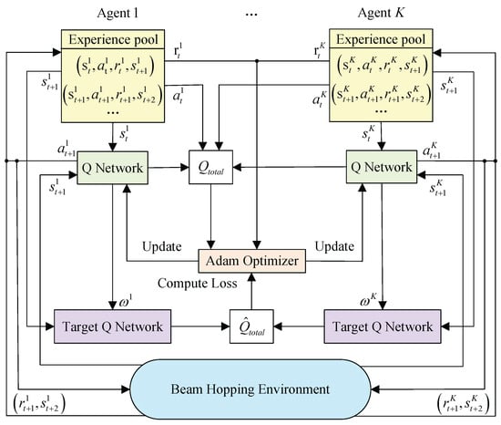
Figure 4.
Cooperative multi-agent VDN algorithm framework for multi-beam satellite.
State space: In this paper, the traffic requests are represented by the data volume of each beam position. In time slot t, the traffic requests of all beam positions are observed as the global state, and each agent can share this global state. It can be expressed as
where is the global state of the beam hopping satellite in time slot t. represents the state information of the k-th agent in time slot t. is the traffic request of each beam position in time slot t. is defined above, representing the traffic demand of beam position m in time slot t. It can be seen from the above formula that the state space matrix is composed of two dimensions: time and beam position. The total data packet delay in the packet buffer queue is obtained by
where represents the time slot when the data packet arrives at beam position m after being generated.
Action space: In the multi-agent architecture of the LEO beam hopping satellite communication system, each service beam dynamically selects a beam position for illumination in each time slot. The above decision-making process involves designing a beam hopping pattern and allocating the corresponding beam power. For the optimization problem in this paper, a total of K agents need to cooperatively make decisions. The joint action in time slot t is expressed as
where represents the joint action of all cooperative multi-agents in time slot t. represents the action of the k-th agent in time slot t. represents the N power allocation schemes of the k-th agent in time slot t, and represents the M beam position illumination schemes of the k-th agent in time slot t.
According to the above definition of the action space, it can be seen that the size of the cooperative multi-agent’s overall action space is . Compared with the overall action space size of the single agent, the multi-agent architecture can effectively reduce the on-board memory.
Reward: Agents receive rewards after taking actions. To minimize the long-term optimization target, we use user satisfaction and the total packet delay as immediate rewards. The reward value after the agent takes an action in time slot t is defined as
where represents the shared reward of all cooperative multi-agents in time slot t, and is the weight coefficient between user satisfaction and delay. From the above text, we can see that there are action constraints among agents, and service beams that operate simultaneously cannot illuminate adjacent beam positions. Otherwise, serious co-channel interference problems will occur. Therefore, the trained agents will avoid illuminating adjacent beam positions when making decisions.
3.2. Cooperative MARL-VDN Algorithm Framework
The parameters of the MARL-VDN network are shown in Table 2. The MARL-VDN algorithm decomposes the joint action–value function of the multi-agent architecture into the sum of individual Q-functions of each agent () through linear addition and decomposition. The decomposition uses global rewards during the training phase to promote the cooperation of multi-agents, centrally optimizes the Q-networks of all agents, and avoids policy conflicts among agents. During execution, each agent only relies on its Q-function to select actions, achieving CTDE.
Table 2.
Parameters of the MARL-VDN network.
The Q-network parameters of each agent are defined as , then the Q-network of the k-th agent in time slot t is expressed as . This paper adopts a variant of the recurrent neural network as a function approximator. In time slot t, agents select and execute the joint action according to the environmental observation and the -greedy strategy. After taking the action, agents obtain the global reward , and the environmental state is updated from to the next state . In a multi-agent environment, synchronous updates of all agents’ strategies will make the environmental dynamics appear non-stationary to individual agents, and individual Q-networks may fall into local optima due to biases in local consecutive samples. To address the above problem, we adopt an experience replay buffer and independent target Q-networks to counter non-stationarity. The experience information is stored in the experience buffer for training the network. To balance gradient variance and computational efficiency, agents randomly select small-batch sample data from the experience buffer to calculate the target value and loss function and update the gradients of the Q-network.
In the MARL-VDN architecture, the target Q-network parameters of agents are defined as . Since its network structure is the same as that of the Q-network, the target Q-network of the k-th agent in time slot t is expressed as . When training the network, after sampling m samples from the experience buffer, the target value of the temporal difference (TD) error can be calculated as
where represents the immediate reward obtained in time slot t. is the discount factor, which is used to measure the importance of future rewards. and are the state and action of the k-th agent in time slot , respectively.
The minimum mean square error loss can be described as
The Adam optimizer is used to simultaneously optimize and update the Q-network parameters of all agents. Finally, through a delayed parameter synchronization update, the parameters of the Q-network are copied to the target Q-network every G steps. The detailed description of the cooperative MARL-VDN algorithm for dynamic beam hopping is shown in Algorithm 1.
| Algorithm 1 Cooperative MARL-VDN algorithm for dynamic beam hopping |
| Input: |
| Number of agents K. |
| Exploration rate . |
| Size of the experience replay buffer . |
| Update frequency of the target Q-network G. |
| Initialize: |
| Initialize an independent Q-network for each agent with randomly generated network parameters . |
| Initialize the target Q-network, set network parameters . |
| Initialize the environment state . |
| Initialize the experience replay buffer D. |
| Training: |
| for episode to do |
| Reset the environment. |
| for time slot to T do |
| for agent to K do |
| Obtain the global state of the agent. |
| Select action using the -greedy strategy. |
| end for |
| Execute the joint action . |
| Obtain the global reward and transition to the next state . |
| Store the experience information in the experience buffer. |
| Each agent randomly samples a mini-batch of samples from the experience replay buffer D. |
| for agent to K do |
| Calculate the target value of the mini-batch data via Equation (24). |
| Calculate the mean squared error loss according to Equation (26). |
| Update the individual Q-network parameters of the agent using the Adam gradient descent algorithm. |
| end for |
| Update the target Q-network parameters of each agent every G time steps. |
| end for |
| end for |
4. Simulation Results and Analysis
In this section, we demonstrate the performance of the algorithm applied in this paper through simulations in the dynamic traffic scenarios of LEO beam hopping satellites.
4.1. Setup and Parameters
The values of the relevant simulation parameters are summarized in Table 3. The LEO beam hopping satellite communication system proposed in this paper operates in the Ka-band with a carrier frequency of 20 GHz. The satellite orbit altitude is assumed to be 550 km. A single satellite is equipped with four service beams, and the satellite-covered ground area is divided into 12 positions. The total system bandwidth is 200 MHz. Each beam has five power options, and the maximum beam power is 8 dBW. The satellite transmission gain is 25 dBi, and the ground reception gain is 45 dBi. Each time slot is set to be 2 ms long, and the maximum residence time of a data packet is 70 ms. Before entering the training period, the arrival of data packets at each position follows a Poisson distribution. During the training period, the traffic demands for each beam position range from 1500 to 2200 Mbps. To reflect the time-varying characteristics of traffic demand, the traffic volume requested by each beam position in each time slot is generated based on its remaining data volume.
Table 3.
LEO satellite simulation parameters.
Table 4 summarizes the parameters of the VDN algorithm framework. In the training phase, we set the number of training episodes to 2000 and the number of time slots in the beam hopping period for each episode to 100. The learning rate is , and the size of the experience pool is 2000. The update frequency of the target network is 100, and the minibatch size is 64. The discount factor is set to 0.9. The initial exploration rate is 1, and the final exploration rate is 0.05.
Table 4.
MARL-VDN parameters.
4.2. Computational Complexity Analysis
The algorithm in this paper will be compared in performance with four other different dynamic beam hopping (DBH) schemes, namely Random Beam Hopping (R-BH), Periodic Beam Hopping (P-BH), Genetic Algorithm Beam Hopping (GA-BH), Delay Fairness Beam Hopping (DF-BH), and Deep Q-Network (DQN). A complexity analysis of each algorithm is presented as follows.
- R-BH: The R-BH algorithm randomly selects K beam positions from M beam positions for irradiation, and the beam power is randomly selected from N elements of the transmitting power set. Therefore, the complexity of the R-BH algorithm is expressed as .
- P-BH: The P-BH algorithm carries out a time division service for different beam positions through a periodic beam hopping pattern. So, the complexity of the P-BH algorithm is expressed as .
- GA-BH [26]: The GA-BH algorithm needs to calculate user satisfaction and delay separately. The computational complexity of the former is , and the computational complexity of the latter is . Therefore, the complexity of the GA-BH algorithm is expressed as , where G represents the maximum number of iterations and P represents the population size.
- DF-BH [27]: The DF-BH algorithm serves the top K beam positions with the largest delay in each time slot. So, the complexity of the DF-BH algorithm is expressed as .
- DQN: The DQN algorithm learns optimal strategies through a neural network, and its computational complexity depends on the complexity of the deep neural network. For a neural network structure with L layers, the dimension of the weight matrix is . In a single forward-propagation calculation, the computational amount of a fully connected layer is , and the computational complexity of the forward propagation of the entire neural network is .
The computational complexity of the MARL-VDN algorithm in this paper depends on the complexity of the RNN variant network. Therefore, the complexity of the algorithm in this paper is , where L is the total number of network layers, is the input dimension of the l-th layer network, is the calculation cost of the activation function, and is the output dimension of the l-th layer network. According to the parameters given in Table 2, we calculate that the algorithm’s complexity in this paper is 33,280 .
4.3. Performance of the Applied Algorithm
The episode rewards of the MARL-VDN algorithm applied in this paper during offline training in a dynamic environment are shown in Figure 5, where the weight coefficient equals 0.5. The weight coefficient is used to balance delay fairness and user satisfaction. The larger is, the more the system emphasizes delay fairness. Conversely, the smaller is, the more the system emphasizes user satisfaction. In this paper, when equals 0.5, multi-agents can better balance the two optimization objectives of delay fairness and user satisfaction. As can be clearly observed from the figure, during the 2000-episode training process, the reward curve gradually rises and eventually converges, which indicates that agents can cooperate with each other during the training process. In addition, the reward curve in the figure not only has fast convergence but also long-term stability, enabling this algorithm framework to adapt to complex and variable traffic demands with ease.
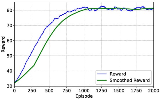
Figure 5.
The episode reward under the optimization weight .
To validate the long-term delay fairness performance of the algorithm, we tested scenarios with different traffic demands in 100 time slots. The traffic demands of each beam position range from 1500 to 2200 Mbps. still equals 0.5. Figure 6 shows the convergence of the average delay of data packets waiting as well as transmission during the training process of the algorithm. We can observe that during the 2000-episode training process, the delay fairness first decreases and then converges to a stable state. Eventually, the delay fairness converges to about 5.2 ms. This result proves that after sufficient training, the algorithm can effectively reduce the average delay of data packets at each beam position in scenarios with different traffic demands; it can achieve good delay fairness, adapt to long-term traffic changes, and has the ability to guarantee long-term delay fairness performance in the multi-agent system.
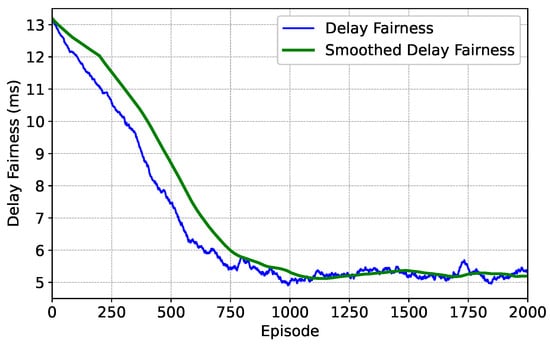
Figure 6.
Episode delay fairness under optimization weight .
Figure 7 shows the episode user satisfaction during the training of the algorithm in a dynamic environment. We can see that during the 2000-episode training process, the user satisfaction gradually increases and stabilizes, and the final satisfaction level remains at 85%. The simulation result indicates that the MARL-VDN algorithm can maintain a high level of resource utilization efficiency in the face of dynamic traffic changes, which strongly verifies the effectiveness of the multi-agent cooperation framework. The gentle characteristic of the latter part of the curve in the figure reflects that the system has strong anti-interference ability and is very suitable for dynamic satellite communication scenarios. In scenarios where ground users are unevenly distributed and demands are time-varying, the algorithm applied in this paper can dynamically adjust the beam resource allocation to effectively guarantee quality of service to most users. Furthermore, the sustained high user satisfaction observed even after 2000 episodes demonstrates the system’s capacity for continuous optimization, effectively adapting to long-term variations in traffic demands.
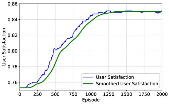
Figure 7.
The episode user satisfaction under the optimization weight .
After training, user satisfaction can be stably maintained at a relatively high level, which reflects the good adaptation relationship between the throughput and the total traffic demand of the algorithm applied in this paper during long-term operation. When the throughput allocated by the system can meet the high traffic demand in the scenario, the situation of data packet loss will also improve. Figure 8 presents the change of the business data packet loss rate during the training process of the algorithm. It can be clearly observed that during the 2000-episode training process, the business data packet loss rate gradually decreases and tends to be stable. Eventually, the business data packet loss rate stably remains at about 23%. The result demonstrates that as training progresses, the algorithm can continuously optimize the resource allocation strategy, effectively reduce the business data packet loss rate, improve the stability and reliability of the system in handling traffic demands, and thus guarantee user satisfaction and system performance.
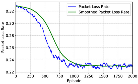
Figure 8.
Episode packet loss rate under optimization weight .
Figure 9 shows the convergence process of the total system power consumption during the training of the algorithm, where the total power consumption refers to the average value of the sum of the power consumption of all service beams used for data transmission. It can be seen from the figure that the total system power consumption eventually converges to around 18 W. In terms of principle, according to the Shannon formula, under the conditions of effectively avoiding interference and given noise, the downlink throughput of beam-positioned users has a logarithmic functional relationship with the transmit power. When the throughput allocated by the system can meet the relatively high traffic demands within the scenario, the power demand per time slot will also be optimized accordingly. Since the number of beam hopping time slots set in this paper is sufficient, business data can be dispersed for transmission in more time slots. The above method of transmission greatly reduces the power demand per time slot, thereby giving the algorithm significant advantages in energy-saving performance. During the training process, compared with the initial stage, the total system power consumption tends to be stable in the second half, and the energy-saving effect of the algorithm remains consistently good, which fully demonstrates that the algorithm framework can withstand environmental changes and achieve efficient energy saving while ensuring service performance. Throughout the iterative process, the algorithm always tends to maintain a relatively low power consumption level, showing good energy-saving characteristics.
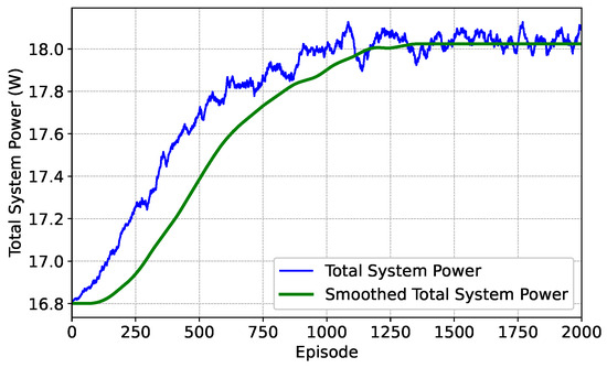
Figure 9.
Episode total power consumption under optimization weight .
4.4. Performance Comparison and Analysis
To verify the long-term throughput performance of the algorithm in the multi-agent system applied in this paper, we tested scenarios with 100 time slots and different traffic demands. Figure 10 shows the relationship between the long-term throughput performance under different methods and different traffic demands. From the figure, we can observe that the performance of the algorithm in this paper outperforms other algorithms. Compared with the RBH, PBH, DF-BH and DQN, the long-term throughput of the algorithm in this paper increases by 30.3%, 22.7%, 13.9%, and 9.5%, respectively. The GA-BH also seeks the optimal solution in the entire action space, so its throughput performance is superior compared to other algorithms. However, due to its high computational complexity, the algorithm in this paper still has an advantage. When the system-provided capacity fails to meet traffic demands, specifically in scenarios where the normalized traffic volume exceeds 100%, the system throughput growth of other algorithms tends to stabilize. Under such conditions, the performance of the MARL-VDN algorithm in terms of system throughput is still significantly better than that of other algorithms.
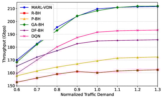
Figure 10.
Long-term system throughput versus normalized traffic demand with .
Similarly, we tested scenarios with 100 time slots and different traffic demands. Figure 11 shows the average packet queuing transmission delay of each method under different traffic demand scenarios. From the figure, we can observe that as the traffic demand increases, the average delay of all algorithms shows an upward trend. Compared with the RBH, PBH, GA-BH, DF-BH, and DQN, the average packet delay of the algorithm in this paper is reduced by 72.6%, 67.8%, 37.6%, 13.9%, and 23.2%, respectively. When the traffic demand exceeds the system capacity, the growth rate of the average delay of the algorithm in this paper is also relatively low. Compared with other algorithms, it can better adapt to different traffic demand scenarios and effectively control the average packet transmission delay.
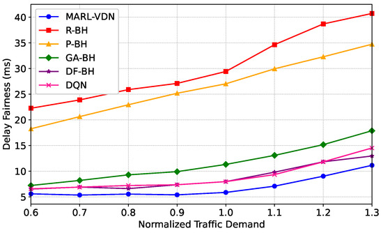
Figure 11.
Delay fairness versus normalized traffic demand with .
To verify the performance of the algorithm applied in this paper in the LEO beam hopping satellite communication system, we conducted tests based on historical service data. The throughput allocation for each ground beam position is shown in Figure 12. It can be seen that the throughput allocated to each beam position is highly compatible with the traffic demand, indicating that the algorithm in this paper can achieve on-board resource allocation on demand and avoid resource waste. The user satisfaction of the ground beam positions is shown in Figure 13. It can be seen from the figure that the user satisfaction level is high and stable, indicating that the algorithm in this paper can continuously guarantee users’ experience in complex service scenarios. The packet delay performance of ground beam positions is shown in Figure 14. It can be observed that the average packet delay across beam positions is approximately 5.6 ms, which meets the real-time traffic requirements of LEO satellite communication. The above-mentioned performance verifies the ability of the algorithm in this paper to achieve on-board resource allocation on demand in dynamic service scenarios.
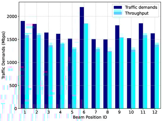
Figure 12.
Throughput performance of the MARL-VDN method.
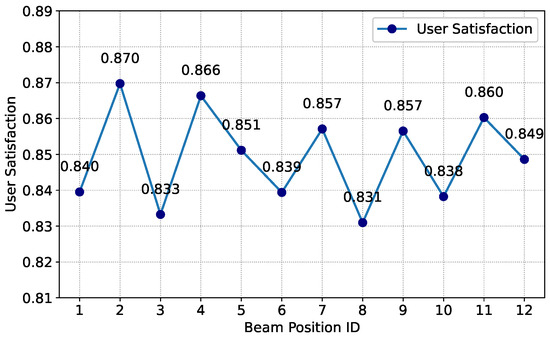
Figure 13.
User satisfaction performance of the MARL-VDN method.
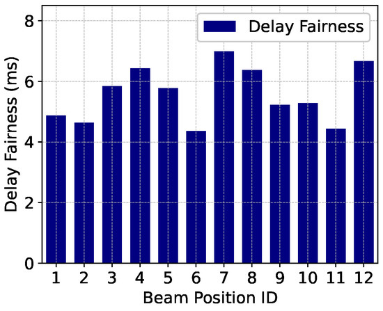
Figure 14.
Delay performance of the MARL-VDN method.
5. Conclusions
This paper focuses on the problem of matching limited satellite resources with dynamic service demands in LEO beam hopping satellite communication systems. To address the above issue, we apply a cooperative MARL-VDN algorithm. The algorithm framework enables cooperative decision making among multiple agents through value decomposition techniques. It adopts the CTDE paradigm. During the training process, a global state and reward-sharing mechanism are introduced, which not only effectively solve the problem of an overly large action space in traditional reinforcement learning but also ensure the convergence of the algorithm and the feasibility of the system. Under the MARL-VDN algorithm framework, we construct a multi-objective optimization model for beam hopping patterns and power allocation decision making, aiming to simultaneously maximize user satisfaction and minimize packet transmission delay. During training, agents continuously optimize strategies by interacting with the environment and learn cooperatively with each other to jointly improve the system’s performance. Deploying the trained agents in a distributed manner in the LEO satellite communication system allows for real-time resource allocation decisions in order to meet service requirements. Our simulation results indicate that the MARL-VDN algorithm demonstrates superior performance in terms of user satisfaction and delay fairness. The MARL-VDN model, after offline training, has strong generalization ability and high execution efficiency, enabling it to flexibly handle diverse scenarios. It provides a practical and efficient solution for the intelligent management of satellite resources in dynamic service scenarios.
Author Contributions
Conceptualization, H.X. and L.L.; methodology, H.X. and L.L.; software, H.X. and L.L.; validation, L.L.; formal analysis, L.L.; investigation, H.X. and L.L.; resources, H.X. and L.L.; writing—original draft, H.X. and L.L.; writing—review and editing, L.L. and Z.Z.; funding acquisition, L.L. and Z.Z.; project administration, L.L.; supervision, L.L. and Z.Z. All authors have read and agreed to the published version of the manuscript.
Funding
This work was supported in part by the National Key Research and Development Program of China under Grant 2022YFB2902100, in part by the National Science Foundation of China under Grant 62401271, in part by the Startup Foundation for Introducing Talent of Nanjing University of Information Science and Technology (NUIST) under Grant 2023r134, and in part by the Natural Science Foundation of the Higher Education Institutions of Jiangsu Province under Grant 24KJB510019.
Data Availability Statement
Data is contained within the article.
Conflicts of Interest
The authors declare no conflicts of interest.
References
- Liu, J.; Shi, Y.; Fadlullah, Z.M.; Kato, N. Space-air-ground integrated network: A survey. IEEE Commun. Surv. Tutor. 2018, 20, 2714–2741. [Google Scholar] [CrossRef]
- Lin, Z.; Ni, Z.; Kuang, L.; Jiang, C.; Huang, Z. Dynamic beam pattern and bandwidth allocation based on multi-agent deep reinforcement learning for beam hopping satellite systems. IEEE Trans. Veh. Technol. 2022, 71, 3917–3930. [Google Scholar] [CrossRef]
- Chen, S.; Sun, S.; Kang, S. System integration of terrestrial mobile communication and satellite communication—the trends, challenges and key technologies in B5G and 6G. China Commun. 2020, 17, 156–171. [Google Scholar] [CrossRef]
- Chen, S.; Liang, Y.C.; Sun, S.; Kang, S.; Cheng, W.; Peng, M. Vision, requirements, and technology trend of 6G: How to tackle the challenges of system coverage, capacity, user data-rate and movement speed. IEEE Wirel. Commun. 2020, 27, 218–228. [Google Scholar] [CrossRef]
- Di, B.; Song, L.; Li, Y.; Poor, H.V. Ultra-dense LEO: Integration of satellite access networks into 5G and beyond. IEEE Wirel. Commun. 2019, 26, 62–69. [Google Scholar] [CrossRef]
- Du, J.; Jiang, C.; Zhang, H.; Wang, X.; Ren, Y.; Debbah, M. Secure satellite-terrestrial transmission over incumbent terrestrial networks via cooperative beamforming. IEEE J. Sel. Areas Commun. 2018, 36, 1367–1382. [Google Scholar] [CrossRef]
- Lei, J.; Vázquez-Castro, M.Á. Multibeam satellite frequency/time duality study and capacity optimization. J. Commun. Netw. 2011, 13, 472–480. [Google Scholar] [CrossRef]
- Wang, C.; Liu, N. Research on software defined spectrum sharing cognitive multi-beam satellite communication system. In Proceedings of the 2019 IEEE 2nd International Conference on Automation, Electronics and Electrical Engineering (AUTEEE), Shenyang, China, 22–24 November 2019; IEEE: Piscataway, NJ, USA, 2019; pp. 598–601. [Google Scholar]
- Lin, Z.; Ni, Z.; Kuang, L.; Jiang, C.; Huang, Z. NGSO satellites beam hopping strategy based on load balancing and interference avoidance for coexistence with GSO systems. IEEE Commun. Lett. 2022, 27, 278–282. [Google Scholar] [CrossRef]
- Fonseca, N.J.; Sombrin, J. Multi-beam reflector antenna system combining beam hopping and size reduction of effectively used spots. IEEE Antennas Propag. Mag. 2012, 54, 88–99. [Google Scholar] [CrossRef]
- Meng, M.; Hu, B.; Chen, S.; Kang, S. Dynamic Beam Pattern Based on Cooperation Multi-Agent VDN-D3QN for LEO Satellite Communication System. IEEE Trans. Green Commun. Netw. 2024, 9, 725–738. [Google Scholar] [CrossRef]
- Shaohui, S.; Liming, H.; Deshan, M. Beam switching solutions for beam-hopping based LEO system. In Proceedings of the 2021 IEEE 94th Vehicular Technology Conference (VTC2021-Fall), Virtual, 27–28 September 2021; IEEE: Piscataway, NJ, USA, 2021; pp. 1–5. [Google Scholar]
- Kibria, M.G.; Lagunas, E.; Maturo, N.; Spano, D.; Chatzinotas, S. Precoded cluster hopping in multi-beam high throughput satellite systems. In Proceedings of the 2019 IEEE Global Communications Conference (GLOBECOM), Big Island, HI, USA, 9–13 December 2019; IEEE: Piscataway, NJ, USA, 2019; pp. 1–6. [Google Scholar]
- Diao, R.; Zhang, X.; Zhang, L.; Zheng, S.; Quan, Q. A Muti-beam Placement Optimization Scheme in LEO Beam Hopping Satellite Systems. In Proceedings of the 2023 International Conference on Wireless Communications and Signal Processing (WCSP), Hangzhou, China, 2–4 November 2023; IEEE: Piscataway, NJ, USA, 2023; pp. 658–663. [Google Scholar]
- Li, W.; Zeng, M.; Wang, X.; Fei, Z. Dynamic beam hopping of double LEO multi-beam satellite based on determinant point process. In Proceedings of the 2022 14th International Conference on Wireless Communications and Signal Processing (WCSP), Nanjing, China, 1–3 November 2022; IEEE: Piscataway, NJ, USA, 2022; pp. 713–718. [Google Scholar]
- Li, T.; Yao, R.; Fan, Y.; Zuo, X.; Jiang, L. Multiobjective optimization for beam hopping and power allocation in dual satellite cooperative transmission networks. IEEE Syst. J. 2023, 17, 3870–3881. [Google Scholar] [CrossRef]
- Shi, S.; Li, G.; Li, Z.; Zhu, H.; Gao, B. Joint power and bandwidth allocation for beam-hopping user downlinks in smart gateway multibeam satellite systems. Int. J. Distrib. Sens. Netw. 2017, 13, 1550147717709461. [Google Scholar] [CrossRef]
- Lei, L.; Lagunas, E.; Yuan, Y.; Kibria, M.G.; Chatzinotas, S.; Ottersten, B. Beam illumination pattern design in satellite networks: Learning and optimization for efficient beam hopping. IEEE Access 2020, 8, 136655–136667. [Google Scholar] [CrossRef]
- Zhang, T.; Zhang, L.; Shi, D. Resource allocation in beam hopping communication system. In Proceedings of the 2018 IEEE/AIAA 37th Digital Avionics Systems Conference (DASC), London, UK, 23–27 September 2018; IEEE: Piscataway, NJ, USA, 2018; pp. 1–5. [Google Scholar]
- Sunehag, P.; Lever, G.; Gruslys, A.; Czarnecki, W.M.; Zambaldi, V.; Jaderberg, M.; Lanctot, M.; Sonnerat, N.; Leibo, J.Z.; Tuyls, K.; et al. Value-decomposition networks for cooperative multi-agent learning. arXiv 2017, arXiv:1706.05296. [Google Scholar]
- Zhang, Y.; Wang, Y.; Zhang, Q.; Jia, H.; Feng, L. Optimizing Beam Hopping in Multibeam NGSO Constellations with Multi-Agent Reinforcement Learning. In Proceedings of the 2024 IEEE International Workshop on Radio Frequency and Antenna Technologies (iWRF&AT), Shenzhen, China, 31 May–3 June 2024; IEEE: Piscataway, NJ, USA, 2024; pp. 476–481. [Google Scholar]
- Hu, X.; Zhang, Y.; Liao, X.; Liu, Z.; Wang, W.; Ghannouchi, F.M. Dynamic beam hopping method based on multi-objective deep reinforcement learning for next generation satellite broadband systems. IEEE Trans. Broadcast. 2020, 66, 630–646. [Google Scholar] [CrossRef]
- Liu, H.; Wang, Y.; Wang, T.; Li, P. User-Level Dynamic Beam Hopping Design for LEO Satellite Networks Based on Deep Reinforcement Learning Assisted Enhanced Genetic Algorithm. In Proceedings of the 2024 IEEE 99th Vehicular Technology Conference (VTC2024-Spring), Singapore, 24–27 June 2024; IEEE: Piscataway, NJ, USA, 2024; pp. 1–7. [Google Scholar]
- Ran, Y.; Tan, F.; Chen, S.; Lei, J.; Luo, J. Towards beam hopping and power allocation in multi-beam satellite systems with parameterized reinforcement learning. IEEE Trans. Veh. Technol. 2024, 73, 14050–14055. [Google Scholar] [CrossRef]
- Wen, J.; Wang, C.; Zhao, X.; Chen, R.; Wang, W. Beam Hopping and Power Allocation of LEO Multi-Satellite Communication Network Based on Multi-Agent DQN Algorithm. In Proceedings of the 2024 10th International Conference on Computer and Communications (ICCC), Chengdu, China, 13–16 December 2024; IEEE: Piscataway, NJ, USA, 2024; pp. 1832–1839. [Google Scholar]
- Angeletti, P.; Fernandez Prim, D.; Rinaldo, R. Beam hopping in multi-beam broadband satellite systems: System performance and payload architecture analysis. In Proceedings of the 24th AIAA International Communications Satellite Systems Conference, San Diego, CA, USA, 11–14 June 2006; p. 5376. [Google Scholar]
- Han, H.; Zheng, X.; Huang, Q.; Lin, Y. QoS-equilibrium slot allocation for beam hopping in broadband satellite communication systems. Wirel. Netw. 2015, 21, 2617–2630. [Google Scholar] [CrossRef]
Disclaimer/Publisher’s Note: The statements, opinions and data contained in all publications are solely those of the individual author(s) and contributor(s) and not of MDPI and/or the editor(s). MDPI and/or the editor(s) disclaim responsibility for any injury to people or property resulting from any ideas, methods, instructions or products referred to in the content. |
© 2025 by the authors. Licensee MDPI, Basel, Switzerland. This article is an open access article distributed under the terms and conditions of the Creative Commons Attribution (CC BY) license (https://creativecommons.org/licenses/by/4.0/).