Abstract
In recent years, vibration control utilizing smart materials has garnered considerable attention. In this paper, we aim to achieve vibration suppression of a plate structure with a tail-fin shape by employing piezoelectric actuators—one of the smart materials. The plate structure is rigorously modeled based on the Kirchhoff–Love plate theory, while the piezoelectric actuators are formulated in accordance with the Prandtl–Ishlinskii model. This research proposed a control system that addresses the interference effects arising during vibration control by dividing multiple piezoelectric elements into two groups and implementing MIMO control. The efficacy of the proposed control method was validated through simulations and experiments.
1. Introduction
In recent years, structures such as aircraft and satellites have become increasingly robust and lightweight through the use of polymer materials, such as carbon fiber. Notably, the vertical stabilizer of an aircraft plays a critical role in ensuring stable flight. It is posited that increasing the surface area of the vertical stabilizer enhances the stability of the aircraft. However, at altitudes around 10,000 m, where aircraft typically operate, powerful winds and turbulence can induce unforeseen vibrations in the vertical stabilizer, potentially leading to fatigue failure. Indeed, there have been instances of aircraft accidents resulting from damage to the vertical stabilizer, underscoring the need for effective countermeasures. Smart materials have garnered attention for their potential in vibration control [1]. Smart materials are those that possess actuator and sensor functionalities, as well as self-repair and self-diagnosis capabilities. Examples include piezoelectric elements, magnetostrictive alloys, and shape memory alloys, which are actively being researched and are anticipated to play significant roles in fields such as vibration control and medicine [2,3]. Among these, piezoelectric elements are particularly suited for the generation and sensing of bending motions. Piezoelectric elements, composed of ferroelectric materials, exhibit both the direct piezoelectric effect, where mechanical stress induces a proportional surface charge polarization, and the converse piezoelectric effect, where the application of an electric field induces deformation in the piezoelectric material. These properties enable piezoelectric elements to function as sensors, converting displacement into voltage, and as actuators, converting voltage into displacement. Moreover, piezoelectric elements are highly suitable for vibration control due to their rapid input–output response, frictionless operation, compact and lightweight design, and ease of application. However, piezoelectric actuators exhibit hysteresis nonlinearity, where their output depends not only on the current input but also on the initial state and past inputs, complicating precise control and potentially diminishing the expected control efficacy. In this study, the hysteresis nonlinearity of piezoelectric actuators is formulated using the Prandtl–Ishlinskii model to achieve precise control [4,5,6].
Previous research has explored vibration suppression in cantilever beams using piezoelectric actuators and analyzed the vibrations excited in thin plates when using piezoelectric elements [7,8]. However, these studies often linearize or ignore the hysteresis nonlinearity in the input–output relationship of piezoelectric elements during control. Generally, when constructing control systems for nonlinear control targets, linear approximation of the control target is employed to apply linear control theory. This linearization can degrade the performance of the control system in terms of response speed, tracking accuracy, and sensitivity to characteristic variations, and may impose constraints on the controllable region. To address these issues, research on robust designs for control targets exhibiting nonlinearities, such as hysteresis, has been actively pursued. While H-infinity control and sliding mode control are well-known nonlinear control theories [9,10,11,12], in the field of vibration control, approaches such as sliding mode control, fuzzy control, and LQR-based control have been employed. In this paper, operator theory is adopted to facilitate the construction of a stable and robust control system for nonlinear systems, thereby compensating for the nonlinearity of piezoelectric elements [13,14,15,16]. In previous studies, operator theory has shown success in controlling vibrations in flexible arms using smart materials such as shape-memory alloys (SMA) [17].
The objective of this study is to eliminate interference in MIMO systems for vibration suppression in flat plate structures. Previous studies have attempted to eliminate the effects of interference in vibration suppression systems by using M-SVR, a machine learning method that extends support vector regression (SVR) for multiple inputs and a single output, to estimate and mitigate interference [18]. However, the effectiveness of this approach depends on the accuracy of the training data and the computational cost. Therefore, this study introduces a control system designed to eliminate the effects of interference, thereby achieving high-precision interference suppression. While control systems capable of removing interference have been proposed in previous research, few have theoretically designed interference elimination operators. Previous studies have demonstrated that in the nonlinear temperature control of aluminum plates using Peltier elements, robust stability and perfect output tracking can be achieved by designing a robust tracking filter [19]. Moreover, by employing a filter algorithm to estimate the viscoelasticity of a time-varying multi-joint human arm, the estimation of unknown time-varying parameters in the control target was made possible [20]. Furthermore, by combining an operator designed to eliminate the effects of time delays in control targets with unknown time-varying delays and real-time measured data, the successful removal of these time delays has been achieved [21].
It has been demonstrated that by designing an appropriate filter, it is possible to achieve both the desired performance and robust stability. Additionally, it is evident that by combining the operator with real-time measured data, factors that negatively impact the control system can be eliminated. In this study, we focus on the primary vibration modes occurring in the flat plate and, through the design of an operator aimed at eliminating these modes, along with online optimization, we seek to remove the effects of interference and disturbances in the control target.
In previous studies, research was conducted on SISO systems; however, a system extended to a MIMO configuration has been developed. Conventional control in MIMO systems compensated for interference using a model equation for interference. In this paper, a control system was designed to compensate for interference, disturbances, and the nonlinearity of piezoelectric elements through the design of the operator [18,22]. This paper is structured as follows: In Section 2, the vibrations occurring in a flat plate structure shaped like a tailplane, which serves as the control target, are formulated mathematically. Additionally, the model of the piezoelectric actuators is also formalized. Section 3 addresses the design of a control system based on operator theory, where a system capable of eliminating interference and disturbances is devised, and the methodology is explained in detail. In Section 4, the control system designed in the previous section is evaluated through simulations and real-world experiments to confirm its effectiveness. Finally, in Section 5, the conclusions of this paper are summarized.
2. Modeling
In this study, we verify the vibration suppression effect on the plate using the experimental system shown in Figure 1.
Figure 1.
Schematic of piezoelectric actuator and servo motor mounted on a flat plate.
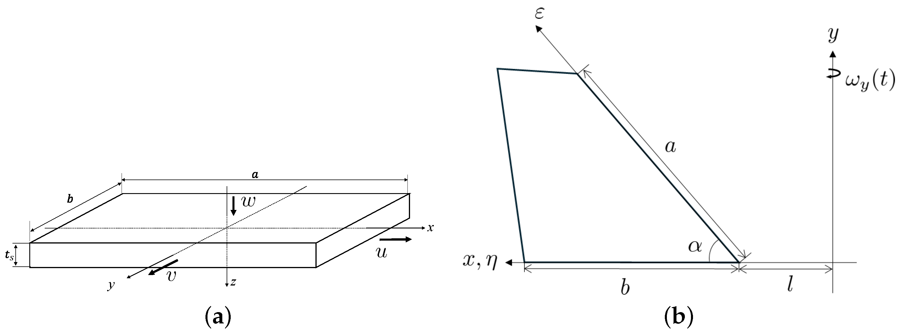
2.1. Modeling of Flat Plate
In this study, although the target plate structure for control takes the shape of a trapezoid, for the sake of simplicity, we derive the equations of motion for a plate with a simple rectangular shape. The equations of motion for the plate structure, which serves as the control target in this research, are derived based on Classical Plate Theory. This theory pertains to thin plates, and the Kirchhoff–Love plate theories are incorporated. By employing the Kirchhoff–Love plate theories, the following constraints are imposed on the plate:
- The thickness of the plate remains constant.
- Shear deformation acting in the direction perpendicular to the surface is neglected.
The equations of motion are derived for the case where stress is applied to a rectangular plate, as illustrated in Figure 2. The parameters employed in the modeling of the controlled object are detailed in Table 1. According to the Kirchhoff–Love plate theories, , and are zero. Consequently, the strain induced in the plate can be expressed as follows.
Here, assuming that the stress distribution within the plate is in a state of plane stress, in accordance with the Kirchhoff–Love plate theories, the relationship between stress and strain can be expressed as follows.
By substituting Equations (1)–(3) into Equations (4)–(6), the stress distribution within the plate can be derived.
By integrating Equations (7)–(9) across the thickness direction, the bending moment generated by the stress distribution within the plate can be derived.
where, in Equations (10)–(12), represents the bending rigidity. From the equilibrium of the shear forces in the X-direction, , and in the Y-direction, , the equation of motion in the Z-direction is expressed as follows.
The moments about the x-axis and y-axis can be obtained by partially differentiating the equations shown in Equations (10)–(12).
By substituting Equations (14) and (15) into Equation (13), the equation of motion governing the bending of the plate can be derived.
In Equation (16), by defining , the equation can be consolidated as shown in Equation (17).
By consolidating the previous equations, the displacement equation for a simple plate structure can be expressed as shown in Equation (18). Here, represents the external force exerted on the plate by the servo motor [22].
Up to this point, the deflection equation for a simple shape, as depicted in Figure 2a, has been derived. Building on this, the displacement equation for a plate structure resembling a tailplane, as illustrated in Figure 2b, is derived. The resulting displacement can be obtained by superimposing the eigenfunctions of the plate. Hence, the results, computed with attention to the orthogonality of the eigenfunctions, are presented in Equation (19).
In Equation (19), are consolidated as Equations (20)–(24).
The result obtained by solving Equation (19) is given in Equation (25). Here, and denote the eigenfunctions of the plate structure.
The terms and appearing in Equation (25) are defined as shown in Equation (26). Additionally, represents a variable accounting for the influence of external disturbances.
Figure 2.
Flat plate structure: (a) simplified model, (b) shape of tail-fin.
Table 1.
Parameters for modeling of the flat plate system.
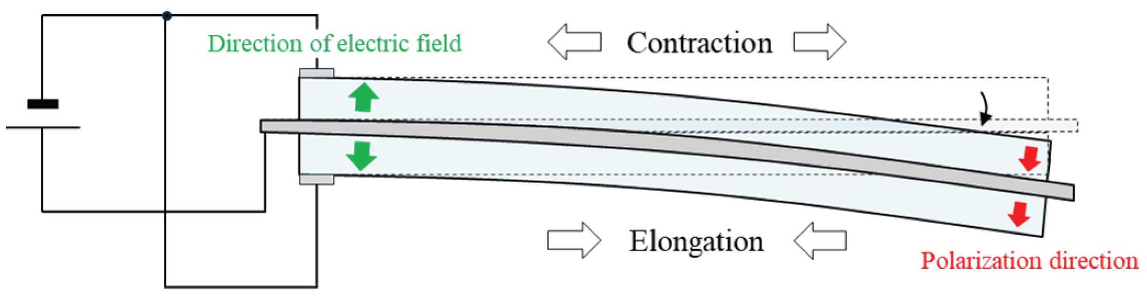
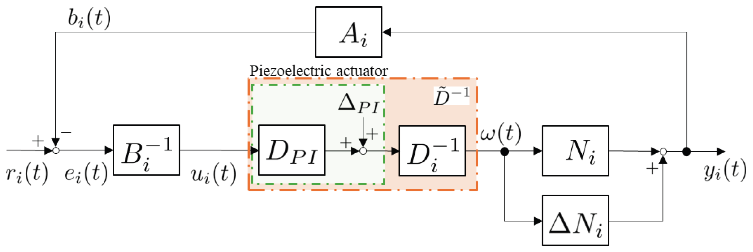
2.2. Modeling of Piezoelectric Actuator
In this study, vibration is suppressed using a bimorph-type piezoelectric actuator. The bimorph piezoelectric actuator consists of a structure where one piezoelectric ceramic is attached to both the front and back surfaces of a thin metallic material. Each piezoelectric ceramic is affixed in such a way that their polarization directions are aligned. Utilizing the property that the piezoelectric ceramic contracts when a forward bias voltage is applied and expands when a reverse bias voltage is applied, the actuator generates a bending motion. Figure 3 illustrates the structure of the bimorph piezoelectric actuator.
Figure 3.
Cross-section of piezoelectric actuator.
Piezoelectric actuators exhibit hysteresis nonlinearity in their input–output relationship. In this study, in order to achieve control that accounts for the hysteresis nonlinearity of piezoelectric actuators, the hysteresis nonlinearity that arises during actuator operation is modeled using the Prandtl–Ishlinskii model, which is based on the Play hysteresis operator [23]. The Prandtl–Ishlinskii model is expressed by the superposition of the Play hysteresis operator .
In Equation (27), represents the input, and r denotes the threshold. The Prandtl–Ishlinskii model expresses hysteresis by weighting and superimposing the Play hysteresis operators using a density function related to the threshold r. The Prandtl–Ishlinskii model is represented by the following equation.
In Equation (28), represents the reversible term, while denotes the residual term. As shown in Equation (29), is the product of the integral of the density function over the threshold R and the input signal. By designing the operator that includes this to satisfy the Bézout equation, it becomes possible to achieve control that accounts for the effects of the piezoelectric actuator. However, is defined as the largest number satisfying and .
The input–output relationship of the piezoelectric actuator, with the input specified as , is presented in Figure 4a. Additionally, the waveforms of , , and in the output of the piezoelectric actuator are illustrated in Figure 4b. From Figure 4b, it can be observed that the reversible term and the residual term are out of phase with each other, resulting in a decrease in the output .
Figure 4.
Hysteresis of piezoelectric actuator: (a) hysteresis loop, (b) elements of hysteresis.
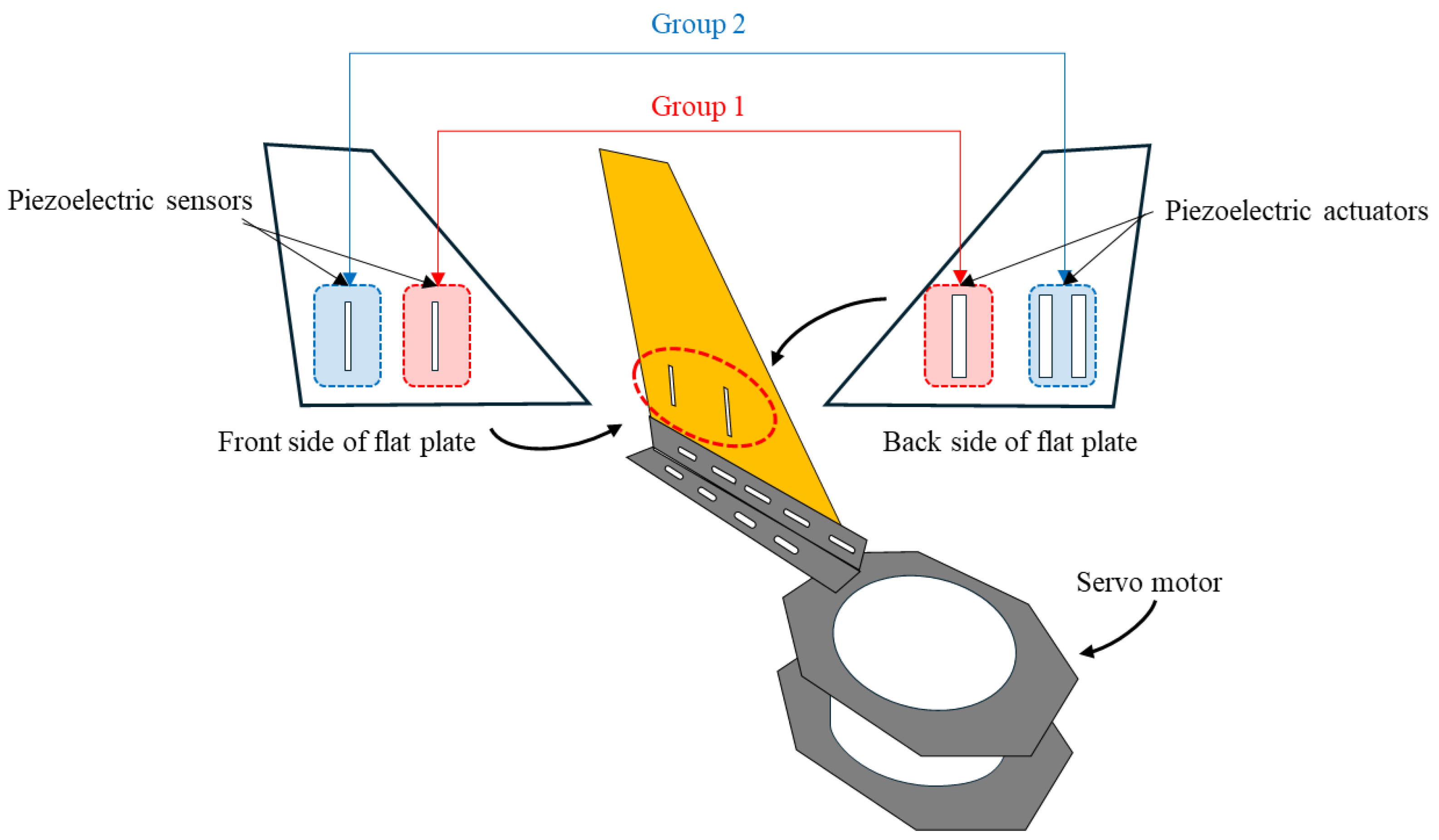
2.3. Problem Statement
By operating the servo motor in a manner similar to a car’s windshield wiper, vibrations are induced in the plate. The generated vibrations are then controlled using three piezoelectric actuators and two piezoelectric sensors installed on the plate, and the effectiveness of the vibration control is evaluated. In achieving vibration suppression, a control system based on operator theory is designed to compensate for the stability in the nonlinear control system that accounts for the hysteresis nonlinearity of the piezoelectric elements. Furthermore, to enhance vibration suppression performance, a control system capable of eliminating interference is devised. The effectiveness of the designed control system is verified through simulations and real-world experiments.
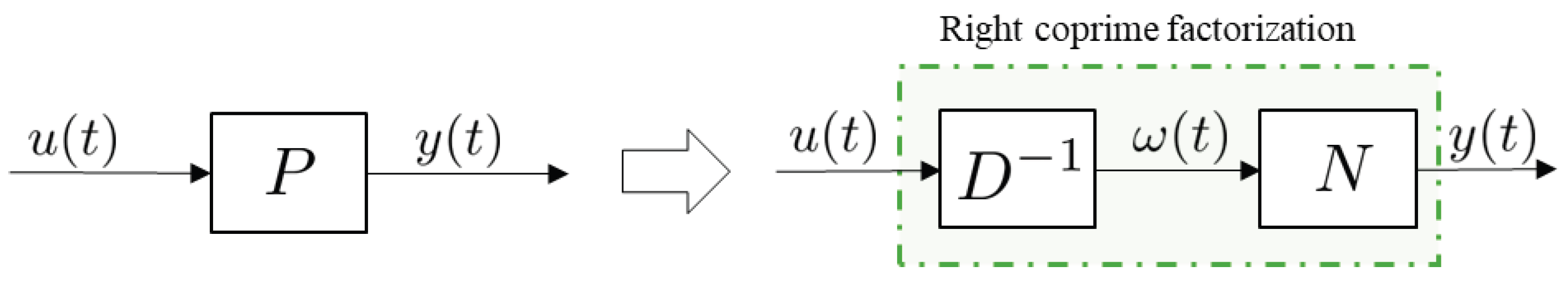
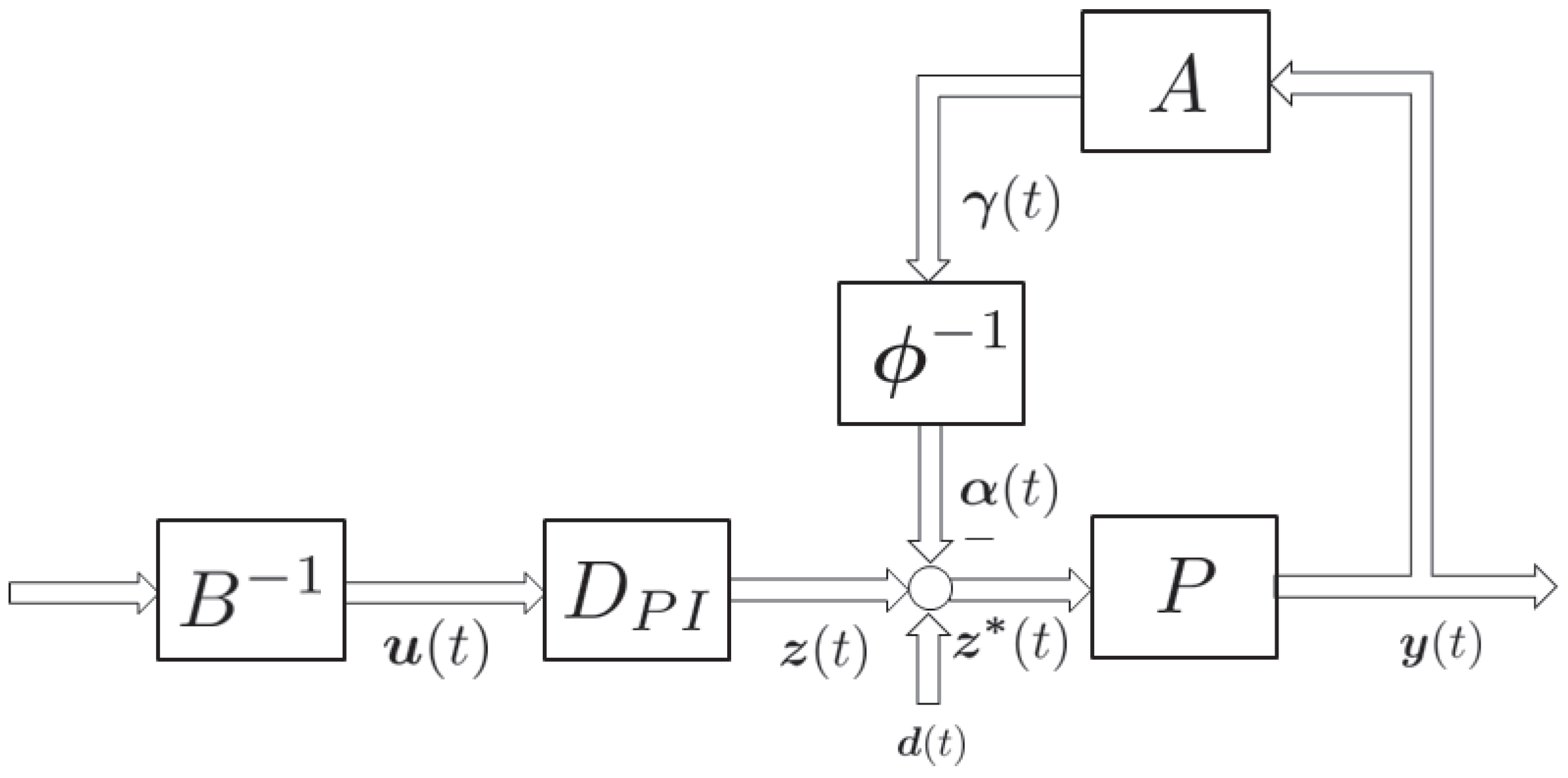
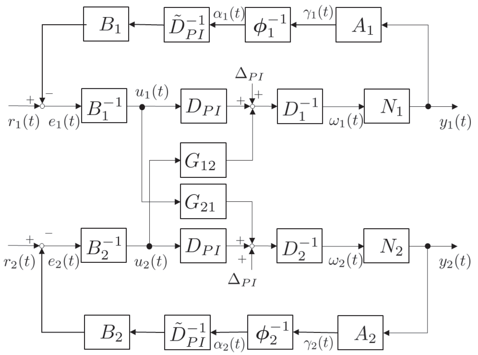
3. Control System Design
Based on the physical models of the plate structure and piezoelectric actuator derived in the previous section, we will design a control system using operator theory. First, the control plant is subjected to right coprime factorization. The right coprime factorization is illustrated in Figure 5.
Figure 5.
Right coprime factorization.
By performing right coprime factorization on Equation (25), it can be decomposed as follows. In this study, the first mode is treated as the nominal plant, while the second and third modes are considered as uncertainties.
Applying right coprime factorization to the equation shown in (25) results in the following form.
Furthermore, based on the Prandtl–Ishlinskii model, the operator considering the input–output characteristics of the piezoelectric actuator, as expressed in Equation (28), is represented as . The control system utilizing operators that satisfy the Bézout equation is illustrated in Figure 6.
Figure 6.
Control system satisfying right coprime factorization.
By designing controllers A and B such that the derived and N satisfy the Bézout equation, the resulting operators take the form shown in Equations (36) and (37). Here, in Equation (37) denotes the design parameter, while represents a constant related to the piezoelectric element.
The Bézout equation is an equation of the form shown in Equation (38). In this equation, represents a unimodular operator, which is defined as the identity operator in this study.
In this study, three piezoelectric actuators and two piezoelectric sensors are divided into two groups, each controlled separately. Group 1 consists of one piezoelectric actuator and one piezoelectric sensor, while Group 2 comprises two piezoelectric actuators and one piezoelectric sensor. The control system is illustrated in Figure 1. To control the MIMO system, the signals from Group 1 influence Group 2, and likewise, the signals from Group 2 affect Group 1. In order to achieve a more efficient vibration suppression system compared to conventional methods, it is essential to eliminate the effects of this interference. The interference occurring in the control system is assumed to result in mutual influence, as illustrated in Figure 7. In this paper, a system in which interference is present, as illustrated in Figure 7, is examined.
Figure 7.
Coupling effect.
In Figure 7, and represent the interference operators that account for the effects of interference, and are expressed as follows, based on previous research.
To theoretically eliminate the effects of interference as shown in Equations (39) and (40), a vibration suppression system is implemented using the control system depicted in Figure 8. In the control system depicted in Figure 8, it is possible to eliminate the effects of disturbance and interference, denoted as . Here, and . By inputting the signal, which includes interference, into the operator designed to eliminate the effects of interference and disturbance, it becomes feasible to eradicate these influences.
Figure 8.
The proposed control system.
In Figure 8, when becomes zero, it is equivalent to the elimination of disturbances and interferences. The signal is represented by Equation (41).
By designing to approach zero, the formulation can be consolidated as shown in Equation (42).
When , Equation (42) is satisfied, thereby eliminating the interference. Figure 9 illustrates the control system that has undergone an equivalent transformation, adapted for the actual system based on Figure 8 and Equation (42).
Figure 9.
Details of the proposed control system.
Design of the Operator
It has been confirmed in Equation (42) that by appropriately designing the operator , the effects of interference and disturbances in the MIMO system can be eliminated. Traditionally, when utilizing the control system shown in Figure 8, the operator was determined through trial and error, posing challenges in the design process. Therefore, in this paper, we proposed a method for determining the operator that exclusively removes interference and disturbances. From previous experiments, it has been confirmed that the vibrational components arising in the control target are predominantly governed by the first mode.
Furthermore, from the mathematical analysis of the interference effects shown in Equations (39) and (40), it can also be verified that the interference is primarily concentrated around the first mode. In Figure 10, a simulation-based comparison is made between the amplitude spectra in the presence and absence of interference effects. Consider the case where Group 1 is subjected to disturbances at the resonance frequency and 9 Hz, while Group 2 is subjected to distinct disturbances at the resonance frequency and 3 Hz. From Figure 10, it is evident that when different disturbances are applied to Group 1 and Group 2, the interference is also influenced by these disturbances. However, it can be observed that a substantial portion of the vibration components due to the interference aligns with the vibrations occurring in the flat plate. The operator for eliminating the effects of interference is presented in Equation (43).
By appropriately designing the parameters in Equation (43), it becomes possible to eliminate signals at the desired frequency. The parameters determined based on , , and become optimal operators for eliminating the effects of interference and disturbances through successive optimization using the gradient descent method. When implementing the operator , Equation (43) is converted using the bilinear transformation, as shown in Equation (44).
In Equation (44), and are expressed as follows.
The evaluation function and update equations for optimizing and are presented in Equations (45)–(47). and represent the parameters after the update.
Figure 10.
Frequency of vibration and interference effects on a flat plate: (a) Group 1, (b) Group 2.
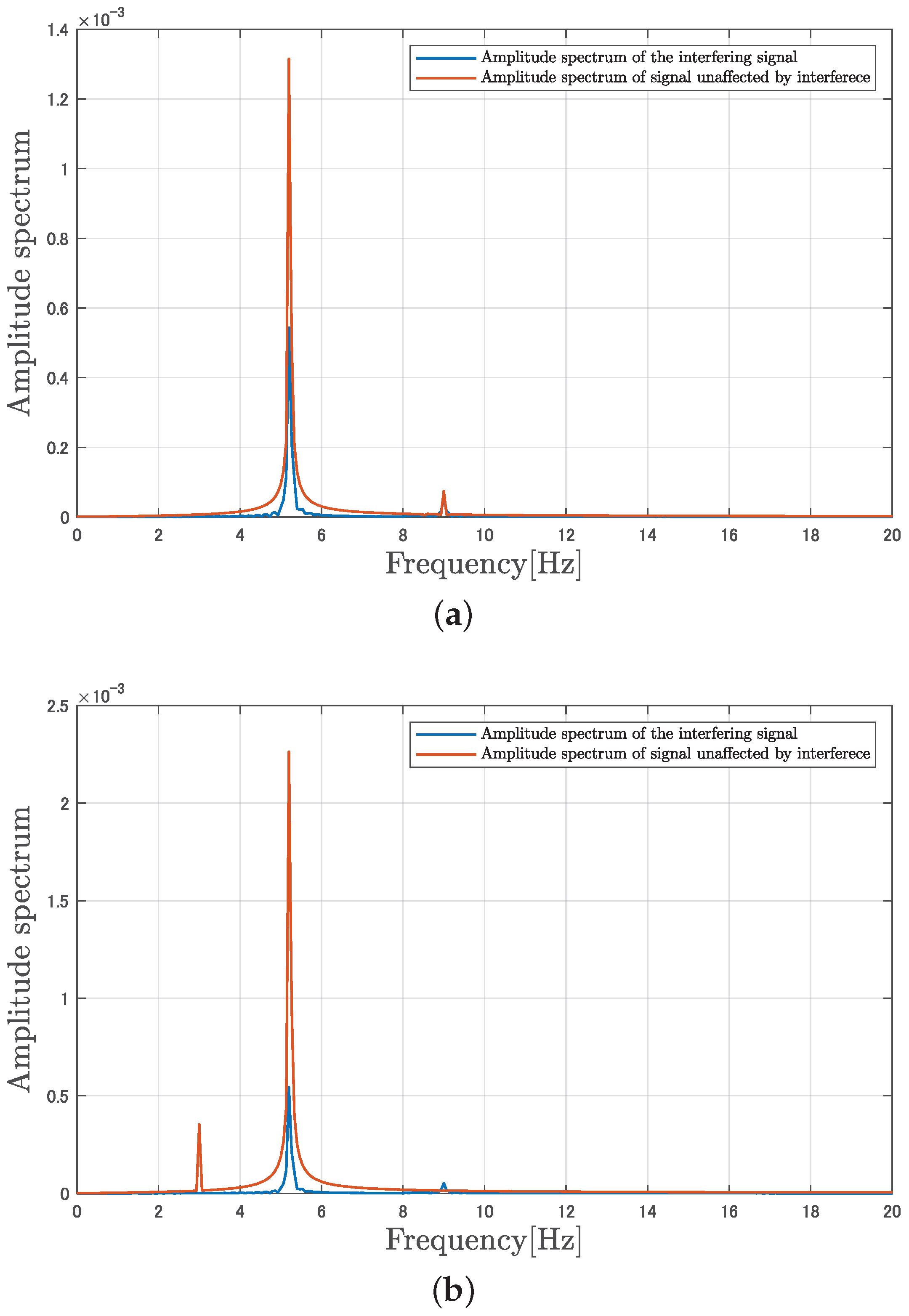
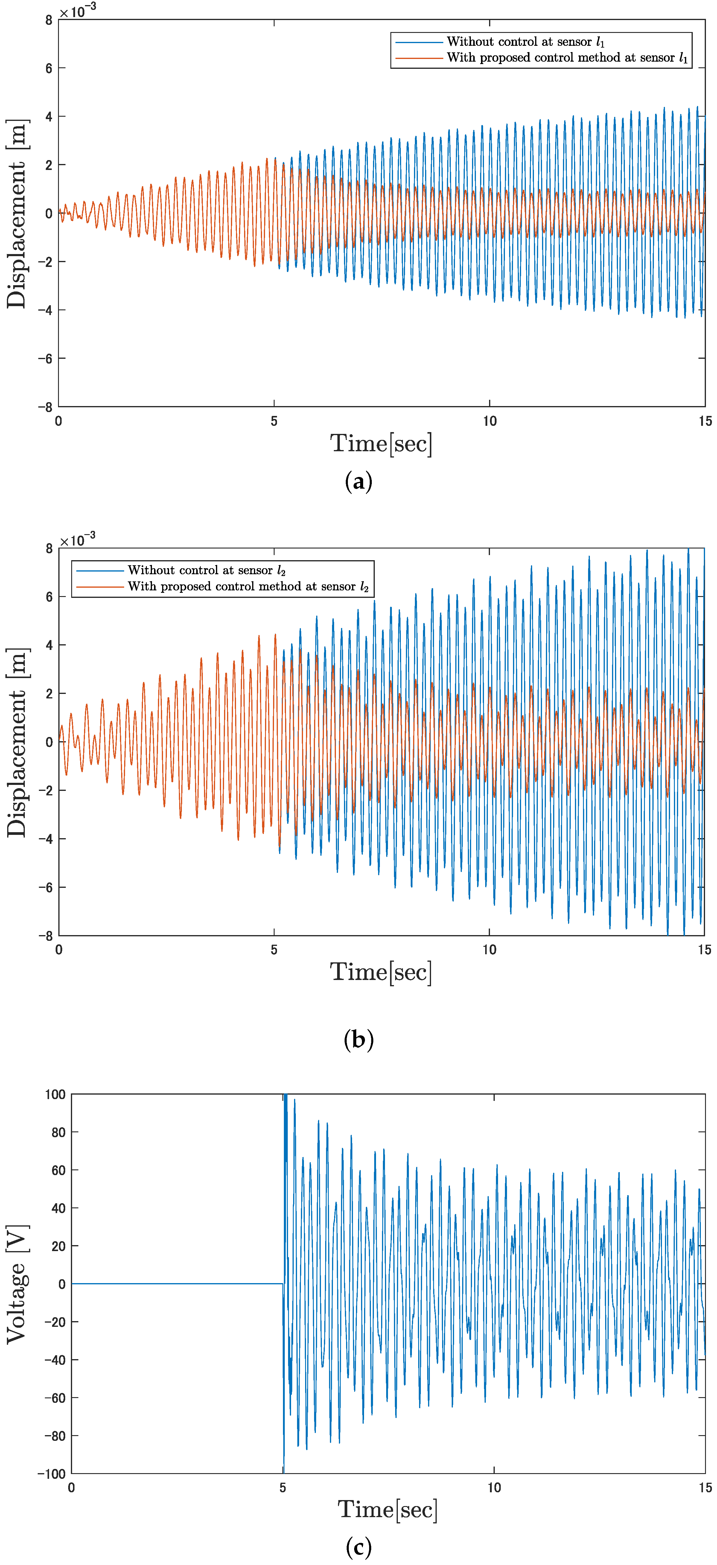
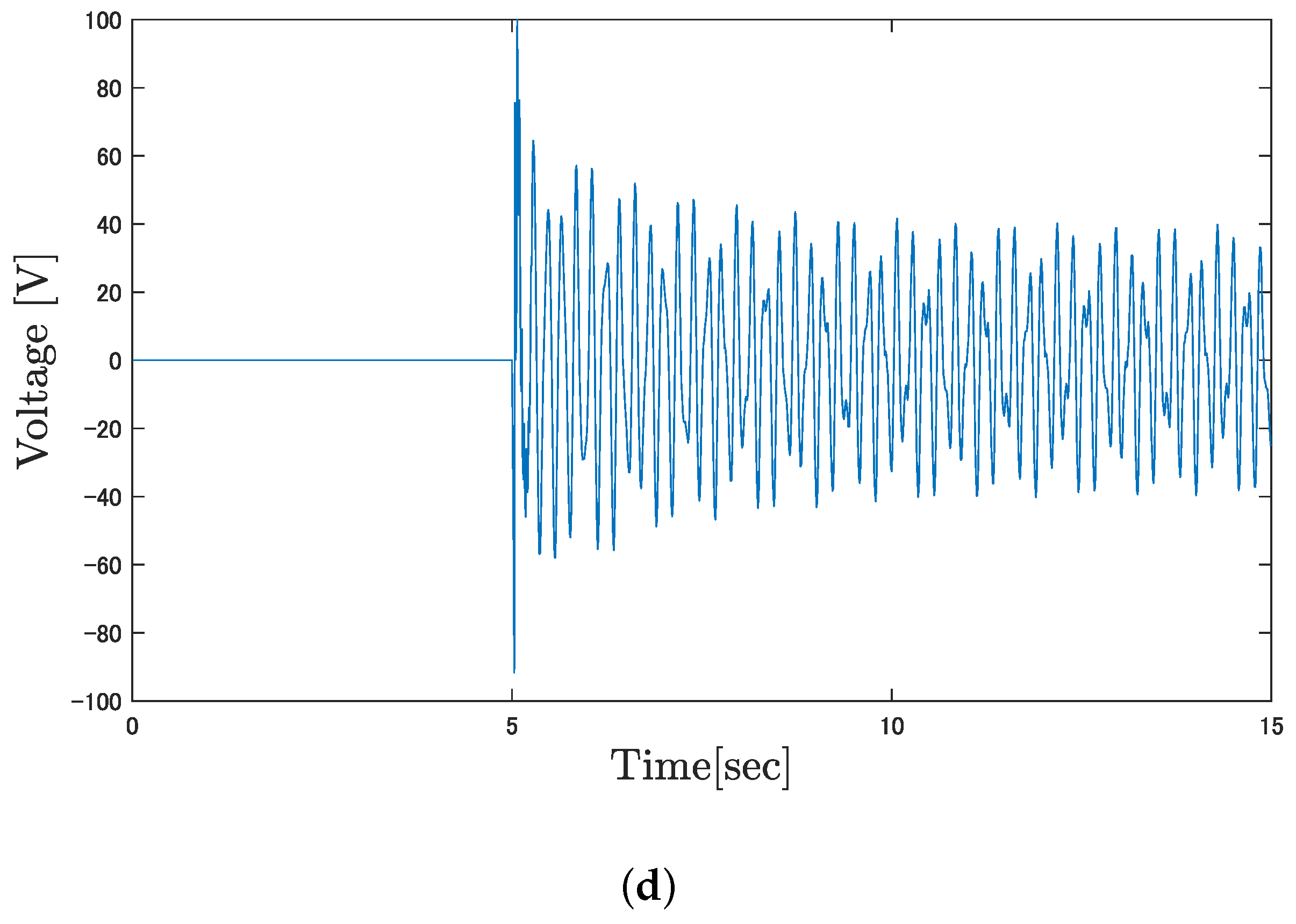
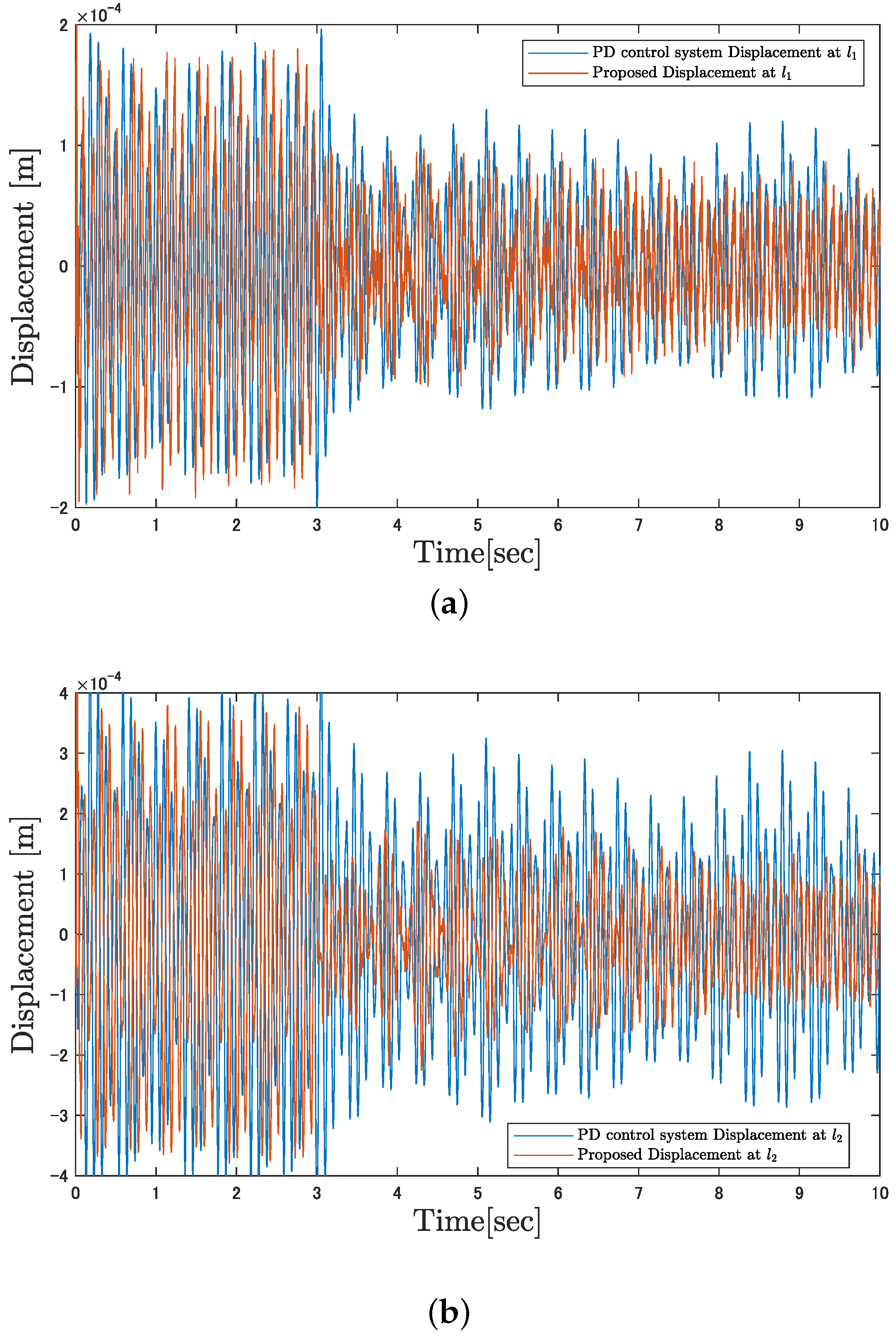
4. Simulation and Experiment
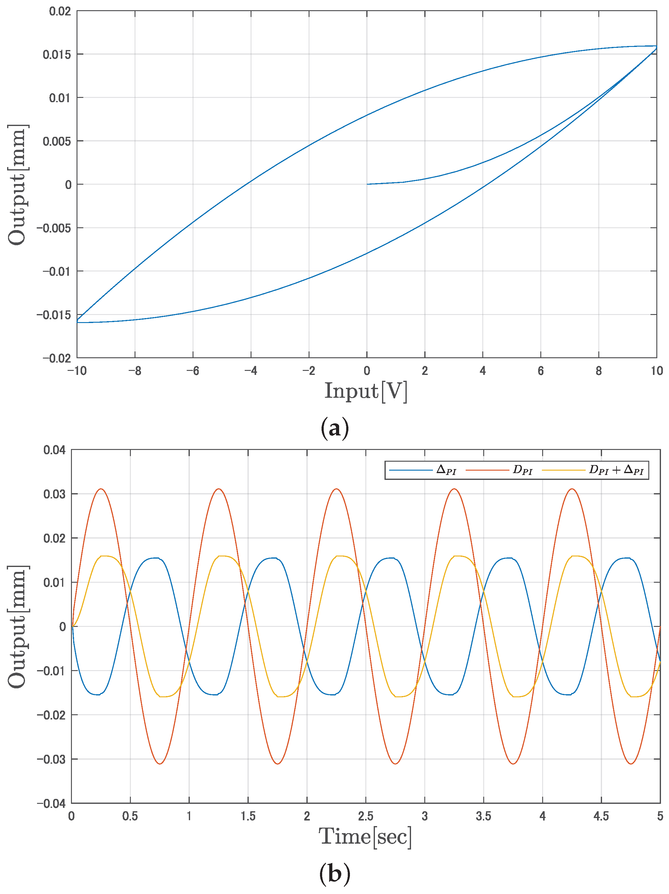
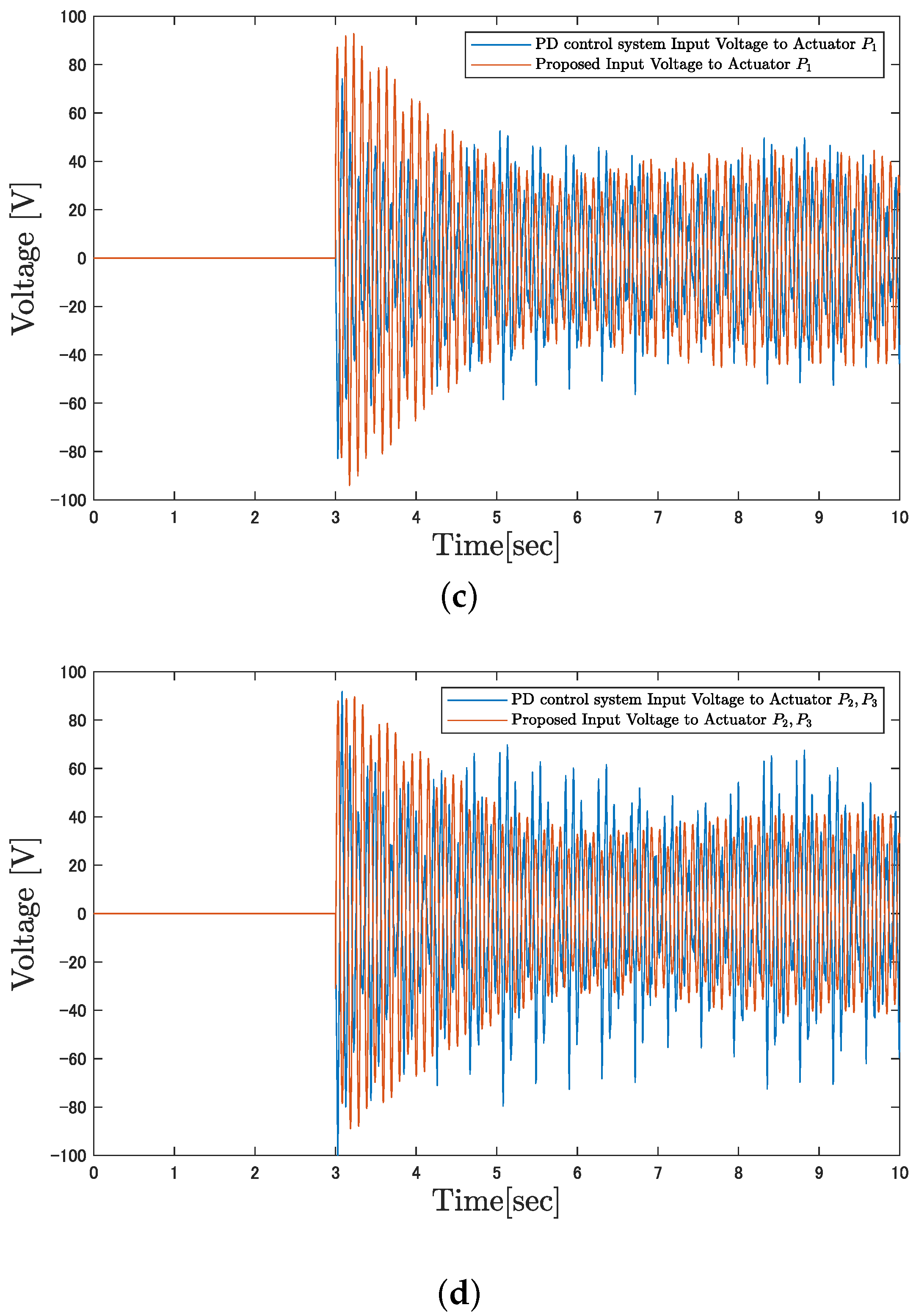
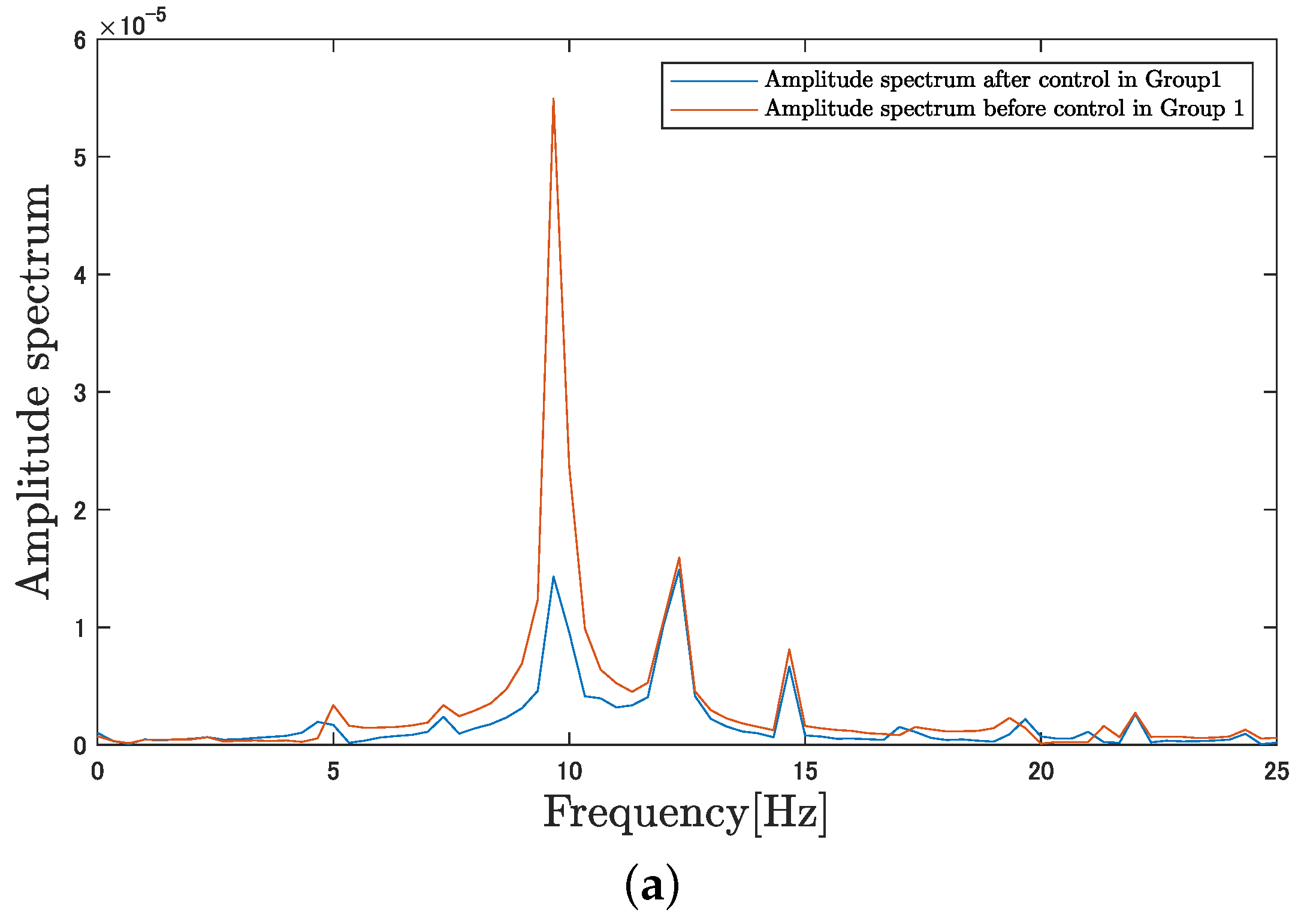
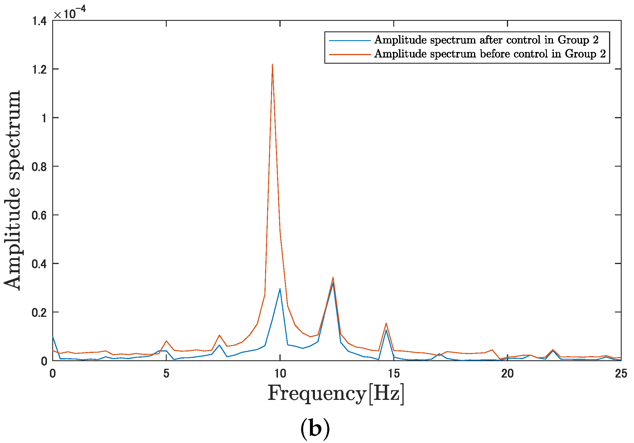
4.1. Simulation Results
This section presents the simulation results of the proposed control system. The parameters used for the simulation are listed in Table 2. The simulation results of the proposed control system are illustrated in Figure 11. In the simulation, distinct disturbances at the resonance frequency and 9 Hz were applied to Group 1, while Group 2 was subjected to disturbances at the resonance frequency and 3 Hz. Figure 11a depicts the vibrations for Group 1, and Figure 11b shows those for Group 2. It can be observed that the vibrations decrease significantly immediately after the control input is applied. Figure 11c shows the control input for Group 1, and Figure 11d represents the control input for Group 2. Although a large input of approximately 100 V is required initially upon the commencement of control, it is evident that, after 10 seconds from the start of the simulation, the input voltage stabilizes within a certain range. The simulation results indicate that, despite the presence of interference from varying frequencies in each group, sufficient control effectiveness was achieved.
Table 2.
Simulation parameters.

Figure 11.
Simulation results: (a) displacement of Group 1, (b) displacement of Group 2, (c) input voltage of Group 1, and (d) input voltage of Group 2.
4.2. Experiment
This section presents the results of experiments conducted using the actual equipment. In the experiments, a comparison was made with the PD control, which is commonly employed in vibration control. The parameters used for the experiments are shown in Table 3, and the results of the control applied to the actual equipment are depicted in Figure 12. The results confirm that the proposed method effectively suppresses vibrations with comparable voltage levels to the commonly used PD control.
Table 3.
Experimental parameters.

Figure 12.
Experimental results: (a) displacement of Group 1, (b) displacement of Group 2, (c) input voltage of Group 1, and (d) input voltage of Group 2.
Figure 12a depicts the vibrations occurring in Group 1, and Figure 12b shows the vibrations in Group 2. In the actual experiments, the control input was applied three seconds after the commencement of data acquisition. It can be observed that the vibrations occurring in the plate significantly attenuate immediately after the application of the control input. To evaluate control performance, the index of “vibration suppression efficiency” is defined as shown in Equation (48). In Equation (48), denotes the variance of the vibrations prior to the initiation of control, while represents the variance of the vibrations after the control has been applied
Figure 12c represents the control input for Group 1, and Figure 12d indicates the control input for Group 2, revealing that the input voltage decreases as the vibrations in the control target are suppressed. Table 4 summarizes the vibration suppression effects achieved by utilizing the proposed control system.
Table 4.
Experimental result.
Figure 13 illustrates a comparison of the vibration components occurring in the flat-plate structure before and after the initiation of control. Figure 13a presents the results for Group 1, while Figure 13b displays the results for Group 2. From the results, it can be confirmed that the disturbance at 10 Hz imparted by the servo motor has been effectively eliminated.

Figure 13.
Comparison of amplitude spectra before and after control: (a) Group 1, (b) Group 2.
5. Conclusions
In this paper, we developed a MIMO vibration control system tailored for managing the vibrations of plate structures utilizing multiple piezoelectric actuators and demonstrated its effectiveness through both simulations and experiments. Compared to the commonly used PD control in vibration suppression, the proposed control system demonstrated enhanced vibration attenuation performance by designing an interference cancellation operator. Furthermore, by iteratively optimizing the parameters of the interference suppression operator using the gradient descent method, we confirmed that the system can appropriately eliminate interference and disturbances even in the presence of plant uncertainties. In this paper, simulations and experimental validations were conducted to assess the effectiveness of controlling vibrations occurring in the low-frequency region near the first mode. Currently, higher-order modes are considered as uncertainties; however, methods to actively control these modes will also be explored in future work.
Author Contributions
Methodology, M.T.; Software, M.T.; Validation, M.T. and G.J.; Investigation, M.T.; Data curation, G.J.; Writing—original draft, M.T.; Writing—review and editing, M.D.; Supervision, M.D. All authors have read and agreed to the published version of the manuscript.
Funding
This research received no external funding.
Institutional Review Board Statement
Not applicable.
Informed Consent Statement
Not applicable.
Data Availability Statement
Data are contained within the article.
Conflicts of Interest
The authors declare no conflicts of interest.
Abbreviations
The following abbreviations are used in this manuscript:
| MIMO | Multi-input multi-output |
| M-SVR | Multi-output support vector regression |
References
- Trolier-McKinstry, S.; Newnham, R.E. Sensors, Actuators, and Smart Materials. MRS Bull. 1993, 18, 27–33. [Google Scholar] [CrossRef]
- Deng, Z.; Dapino, M.J. Review of magnetostrictive materials for structural vibration control. Smart Mater. Struct. 2018, 27, 113001. [Google Scholar] [CrossRef]
- Kumar, D.; Daudpoto, J.; Chowdhry, B.S. Challenges for practical applications of shape memory alloy actuators. Mater. Res. Express 2020, 7, 073001. [Google Scholar] [CrossRef]
- Kuhnen, K. Modelingidentification and compensation of complex hysteretic nonlinearities: A modified Prandtl-Ishlinskii approach. Eur. J. Control 2003, 9, 407–418. [Google Scholar] [CrossRef]
- Su, C.Y.; Wang, Q.; Chen, X.; Rakheja, S. Adaptive variable structure control of a class of nonlinear systems with unknown Prandtl-Ishlinskii hysteresis. IEEE Trans. Autom. Control 2005, 50, 2069–2074. [Google Scholar]
- Janaideh, M.A.; Su, C.Y.; Rakheja, S. Development of the rate-dependent Prandtl-Ishlinskii model for smart actuators. Smart Mater. Struct. 2008, 17, 035026. [Google Scholar] [CrossRef]
- Bailey, T.; Hubbart, J.E. Distributed piezoelectric polymer active vibration control of a cantilever beam. J. Guid. Control Dyn. 1985, 8, 605–611. [Google Scholar] [CrossRef]
- Dimitriadis, E.; Fuller, C.; Rogers, C. Piezoelectric actuators for distributed vibration excitation of thin plates. J. Vib. Acoust. 1991, 113, 100–107. [Google Scholar] [CrossRef]
- Wu, Y.; Yu, X.; Man, Z. Terminal sliding mode control design for uncertain dynamic systems. Syst. Control Lett. 1998, 34, 281–287. [Google Scholar] [CrossRef]
- Yu, X.; Okyay, K. Sliding-Mode Control with Soft Computing: A Survey. IEEE Trans. Ind. Electron. 2009, 56, 3275–3285. [Google Scholar]
- Rigatos, G.; Siano, P.; Melkikh, A.; Zervos, N. A Nonlinear H-Infinity Control Approach to Stabilization of Distributed Synchronous Generators. IEEE Syst. J. 2018, 12, 2654–2663. [Google Scholar] [CrossRef]
- Cheung, Y.L.; Wong, W.O. H-infinity optimization of a variant design of the dynamic vibration absorber—Revisited and new results. J. Sound Vib. 2011, 330, 3901–3912. [Google Scholar] [CrossRef]
- Lin, C.-Y.; Jheng, H.-W. Active Vibration Suppression of a Motor-Driven Piezoelectric Smart Structure Using Adaptive Fuzzy Sliding Mode Control and Repetitive Control. Appl. Sci. 2017, 7, 240. [Google Scholar] [CrossRef]
- Hashemi, A.; Jang, J.; Hosseini-Hashemi, S. Smart Active Vibration Control System of a Rotary Structure Using Piezoelectric Materials. Sensors 2022, 22, 5691. [Google Scholar] [CrossRef] [PubMed]
- Deng, M.; Inoue, A.; Ishikawa, K. Operator-based nonlinear feedback controldesign using robust right coprime factorization. IEEE Trans. Autom. 2006, 51, 645–648. [Google Scholar] [CrossRef]
- Deng, M.; Saijo, N.; Gomi, H.; Inoue, A. A robust real ime method for estimating human multijoint arm viscoelasticity. Int. J. Innov. Comput. Control 2006, 2, 705–721. [Google Scholar]
- Furukawa, I.; Deng, M. Multiple feedback loops based nonlinear vibration control of a flexible arm with shape memory alloy actuator. In Proceedings of the International Conference on Advanced Mechatronic Systems, Toyama, Japan, 17–20 December 2022; pp. 183–188. [Google Scholar]
- Masuda, K.; Jin, G.; Deng, M. Nonlinear vibration control of MIMO flat plate system considering interference model using M-SVR. In Proceedings of the Technical Meeting on Control, IEEE, Tasmania, Australia, 11 September 2023; pp. 29–33. (In Japanese). [Google Scholar]
- Deng, M.; Inoue, A.; Goto, S. Operator based Thermal Control of an Aluminum Plate with a Peltier Device. In Proceedings of the Second International Conference on Innovative Computing, Information and Control (ICICIC 2007), Kumamoto, Japan, 5–7 September 2007; p. 319. [Google Scholar]
- Deng, M.; Inoue, A.; Zhu, Q. An integrated study procedure on real-time estimation of time-varying multi-joint human arm viscoelasticity. Trans. Inst. Meas. Control 2011, 33, 919–941. [Google Scholar] [CrossRef]
- Wang, A.; Deng, M. Operator-based robust nonlinear tracking control for a human multi-joint arm-like manipulator with unknown time-varying delays. Appl. Math. Inf. Sci. 2012, 6, 459–468. [Google Scholar]
- Nakagawa, T.; Katsurayama, Y.; Deng, M.; Wakitani, S. Nonlinear Vibration Control for an Aircraft Vertical Tail by Using Operator-based Estimation. In Proceedings of the 5th International Symposium on Advanced Control of Industrial Processes (ADCONIP 2014), Hiroshima, Japan, 28–30 May 2014; pp. 403–408. [Google Scholar]
- Krejčí, P.; Sprekels, J. Elastic-ideally plastic beams and Prandtl-Ishlinskii hysteresis operators. Math. Methods Appl. Sci. 2007, 30, 2371–2393. [Google Scholar] [CrossRef]
Disclaimer/Publisher’s Note: The statements, opinions and data contained in all publications are solely those of the individual author(s) and contributor(s) and not of MDPI and/or the editor(s). MDPI and/or the editor(s) disclaim responsibility for any injury to people or property resulting from any ideas, methods, instructions or products referred to in the content. |
© 2024 by the authors. Licensee MDPI, Basel, Switzerland. This article is an open access article distributed under the terms and conditions of the Creative Commons Attribution (CC BY) license (https://creativecommons.org/licenses/by/4.0/).