1. Introduction
Aged bridges need to undergo close visual inspection to validate their structural safety and maintain their useful life; this is particularly necessary in Japan, where most existing bridges were built during the high economic growth period (1954–1972) and road managers are required to conduct close visual inspection every five years [
1]. As of 2022, approximately 34% of the 730,000 bridges in Japan were built more than 50 years ago, and it is expected that this number will reach 59% by 2032 [
2]. Aging bridges experience significant ongoing damage and thus require close inspection at frequent intervals. A shortage of skilled engineers with extensive experience and knowledge has been a major issue in the inspection of such bridges.
The need for labor savings is the main reason why several bridge inspection activities are undertaken by a limited number of engineers. The 2019 revised Road and Bridge Inspection Guidelines [
3] allow inspection methods wherein engineers conducting regular inspections have “determined they can obtain information for diagnosing soundness to a degree equivalent to that of close in-person visual inspection.” It is believed that this will stimulate the introduction of inspection methods using image analysis based on robots or AI, as listed in the Inspection Support Technology Performance Catalog [
4] by the Ministry of Land, Infrastructure, Transport, and Tourism.
In this study, we examined remote inspection methods based on damage detection technology using image analysis by AI, with the aim of optimally minimizing the number of people dispatched to bridge sites. The remote inspection method we study targets visual inspection in order to detect damage through image analysis. We conducted an experiment wherein bridge images and damage detection results were shared in real time between bridge sites and remote offices. We used high-resolution images to share damage conditions between bridge sites and remote offices to verify the details of the damage. For the reason that high-resolution images require a large volume of data, we investigated whether upload times could be reduced through 5G communication, which possesses the ability to transfer large volumes at high speeds. Furthermore, damage conditions were mutually verified through communication between engineers based on an online conference system. The outcomes of the study indicated that remote inspection support using 5G is effective in labor-saving for inspection work and that it is possible to sufficiently verify damage conditions simply through communication between bridge sites and remote offices based on an online conference system. Furthermore, we studied the application of inspection methods and the proper skill-based assignment of bridge engineers based on the soundness of individual bridges rather than providing remote inspection support for all bridges. We then proposed conditions under which remote inspection support could be sufficiently integrated.
2. Literature Review
There has been significant research on the inspection methods using the latest technology, wherein robots photograph bridges and subsequently identify and detect damage from the captured images. We focus on damage detection and determine whether it is an effective approach in bridge inspection.
Dang, et al. improved the detection accuracy using training data that combined recorded inspection images and images taken by unmanned aerial vehicles (UAV), while constructing damage detection models [
5]. The images taken with UAVs have background plants and rivers, but the images in inspection records have little background because they focus on damage. The detection accuracy was improved by using learning data that combined images taken by UAVs with images of inspection records. In addition, the improvement of the detection accuracy for the image of the whole bridge is a problem.
Kimoto, et al. evaluated the degree of damage based on the data that were acquired through four robot technologies [
6]. They demonstrated that in the inspection of a large bridge, the robot could help in the safe and stable acquisition of data, which could determine damage.
Izumi, et al. attempted to improve crack detection accuracy using deep learning based on the attention mechanism, which is frequently employed in natural language processing [
7]. Bridge images classified by the presence or absence of cracks were used as learning data for the damage detection model. High pixel-level results were obtained with a method of low-cost classification.
Nakamura et al. used a combination of object detection and segmentation to detect damage [
8]. Object detection identifies the location and type of damage in the image, and damage in the identified area is detected by segmentation. As a result, it was more accurate than segmentation-only detection.
Although these concepts help improve the efficiency of some inspection tasks involving visual inspection, they do not match the efficiency of conventional close visual inspection. Further, they do not serve as a solution for the decrease in the number of skilled engineers, as mentioned previously.
Remote inspection of reinforced concrete structures using UAVs has also been studied [
9,
10]. Cracks are detected from images taken by UAVs, and reinforced concrete structures such as bridges are reproduced in three-dimensional space (3D space) using the detection result images. This technology helps ensure inspector safety and prioritizes locations that require human intervention. Engineers can inspect the bridge remotely without going to the site. However, they need to take the data back to the office after photographing the bridge, and it takes time to reproduce it in 3D space. This method may cause delays in safety measures against emergency damage.
Being able to ascertain damage from bridge images means engineers can inspect it in remotely located offices. The skilled engineers can reduce travel time to the bridge site, saving labor. In addition, if they inspect in real-time with the engineers on the bridge site, they can immediately instruct to repair the damage. Therefore, in this study, we focus on the operational feasibility of remote inspection supported by damage detection.
3. Image Transmission Experiment Using 5G and 4G
In remote inspection support, a skilled engineer at a remote office verifies damage conditions based on the extracted images. Ascertaining damage occurrence sites and the positional relationship of multiple damages requires images of all bridge sections. Furthermore, high-resolution images are required for a detailed verification of the damage, and this results in a further increase in the number of images and the volume of data. We verified whether worktimes can be shortened further by using 5G instead of 4G to upload the images from bridge sites in real time.
The theoretical maximum upload speed for 4G is about 130 Mbps [
11], while the future theoretical maximum attainable goal for 5G is 10 Gbps [
12]. The theoretical maximum upload speed of 5G at the time of this experiment was about 500 Mbps. However, actual communication is greatly degraded by the environment and system configuration. Therefore, the communication speed was tested before the measurement experiment to check the speed.
3.1. Image Communication Experiment Overview
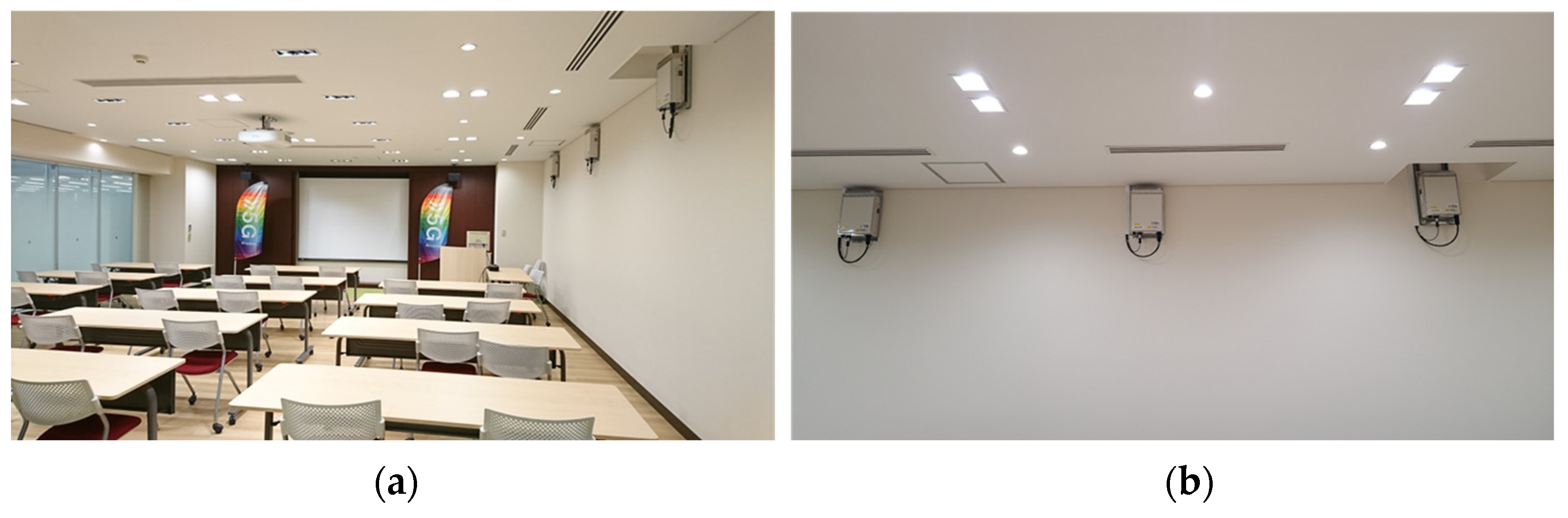
We measured the time required to upload bridge images to a cloud server from the target bridge that was located in a 5G-available area (
Figure 1a). The bridge was constructed in 2005, is 148 m long, and contains six spans. There are a river and riverbed in the clear headway under the girder, and there is a 5G area around the bridge. Photographs of one side of the pier P2 (P1 side) were taken with a Nikon Z50 camera, and they were then composited for damage detection.
The images uploaded were those captured from one side of pier P2 (A1 side) of the bridge. The camera used for photography was a Nikon Z50 (20 million pixels) with a 250-mm lens. Images were taken with a resolution of less than 0.2 mm/px in order to ascertain a 0.2 mm crack. Kimoto et al. found that, with a camera with 20 million pixels or more, the shooting distance with a resolution of 0.2 mm/px or less is 7 m [
13]. Therefore, the photos were taken from a position that is located at a distance of 7 m from the pier (
Figure 1b). Based on the assumption that the photographed images would be used for a composite image, adjacent images were taken with at least 50% overlap.
A total of 17 photographs, each approximately 12 MB in size, were uploaded. The total volume of data for one side of the pier was 196 MB. We compressed the 17 images into a zip file, and we then uploaded the image file to a PC (Mouse model No. PF5MR5G) that was connected to a K5G-C-100A 5G router via LAN. We then uploaded it to OneDrive’s cloud storage via the Internet. For the reason that the router connected can be switched on and off for 5G, we measured the upload time using 4G for the same system configuration. We performed a speed test to measure the communication speed prior to uploading the image a total of three times, and we then verified the communication environment. We performed pier image uploads three times each using 5G and 4G environments, and we computed the average value. The image upload time was measured at two locations: near the bridge and inside NTT Docomo’s 5G testing room, wherein a 5G communication environment was established.
3.2. Image Upload Time Results
Table 1 summarizes the results of image uploads from the target bridge site, which is located in a 5G area. We assumed the use of remote inspection support during inspection work at an actual bridge site. In the preliminary speed test for 5G communication, the average image upload time was 36.8 s for a network connection with an upload speed of 58 Mbps. For 4G communication, the average image upload time was 57.4 s through a connection with an average upload speed of 40 Mbps. The upload time through the 5G network was reduced by approximately 20 s compared with that using 4G. In this experiment, one pier image was communicated. However, it is thought that the time that can be shortened will increase again if all pier images are to be uploaded.
However, because 5G communication is still under the development phase, the communication speed will increase in the future. Therefore, a similar experiment to measure the upload time was conducted in a testing room with a 5G test environment at NTT Docomo (
Figure 2), which presently contains the latest 5G communication tools (
Table 2). The average 5G upload time was 27.1 s through a network with an average upload speed of 233 Mbps. The average upload time in a 4G environment was 45.6 s, and the average upload speed was 41 Mbps.
The upload speed for the preliminary speed test in the 5G testing room was greater than the upload speed of the target bridge 5G speed test by a factor of four. However, the time to upload the data to the cloud was only slightly reduced. The speed limitations may be due to the countermeasures against Denial of Service (DoS) attacks on the cloud server. The DoS attacks are server attacks wherein a large volume of data is sent to a server, thus overloading the server and rendering it unusable [
14]. A countermeasure against DoS attacks is applying a filter in order to send and receive a large volume of data. The OneDrive platform is provided by Microsoft, which employs a variety of countermeasures against DoS attacks. However, specific details, such as whether these countermeasures are aimed at avoiding disclosing detailed information to attackers, are unclear. To maximize 5G communication speed, a private cloud server that allows only communication from predetermined IP addresses is required.
4. Real-Time Remote Inspection Simulation Experiment
4.1. Simulation Experiment Overview
This section highlights the simulation experiment for remote inspection support. Images were uploaded in real time during inspection work, and the damage conditions were verified by a remote engineer.
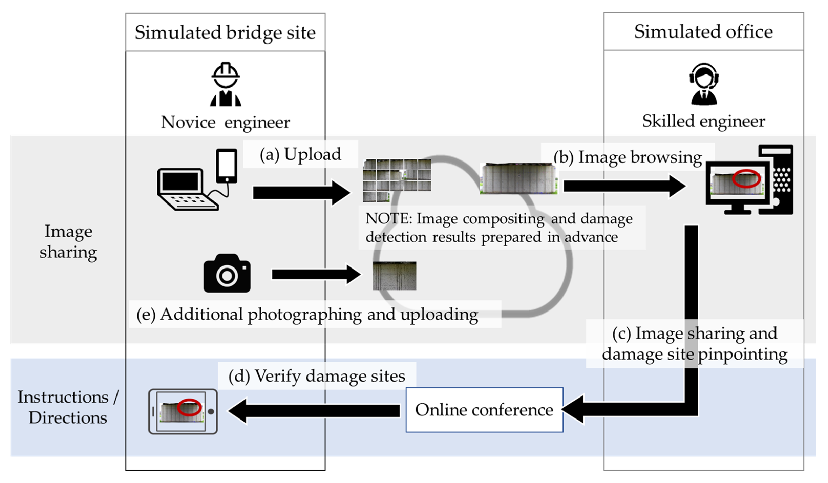
In the simulation, the target bridge served as a simulated bridge site, and a laboratory at the authors’ home institution, Kanazawa University, was the simulated office. The inspection work of a novice engineer at the bridge site was performed by a remotely located skilled engineer (
Figure 3). First, the novice engineer at the bridge site uploaded the bridge images that were taken in advance to the cloud. Next, the skilled engineer at the office downloaded the pier damage detection images and verified them. Image compositing and damage detection were omitted, and pier composite images and damage detection results were prepared on the cloud in advance because we primarily focused on the communication between the engineers in this experiment. The bridge site and office communicated through the Zoom online conference system. The skilled engineer at the simulated office instructed the novice engineer to take additional photographs to verify the details of damaged areas, which were subsequently taken and uploaded to the cloud.
4.2. Damage Detection Image of Bridge Used in Simulation Experiment
Images of damage detection results, as ascertained by remote engineers, were combined and damage detection processed in advance. The composite photographs of the piers were created with the image editing software Photoshop. As the most frequently occurring damage, cracks, concrete exfoliation, exposed rebar, and free lime were targeted for detection.
We constructed a damage detection model using the recorded images as learning data. The detection model of the crack used the detection model created in our previous research [
15]. We created fake crack images based on 545 actual crack images. They were enlarged to 120,000 images by image editing, including image flipping, moving, and scaling. The detection model was trained on these extended data sets. We used a detection model called DeepCrack [
16].
The detection models of concrete exfoliation and exposed rebar were trained on images of inspection records as learning data. The concrete exfoliation detection model was trained with data extended by image editing up to 12,540 images based on 627 actual damaged images. The exposed rebar detection model was trained on data extended by image editing up to 8100 images based on 405 actual damaged images. We used the detection model called SegNet [
17] to detect concrete exfoliation and exposed rebar.
The detection model of free lime was trained on images of inspection records as learning data. The free lime detection model was trained with data extended by image editing up to 920 images based on 92 actual damaged images. We used a detection model called DeepCrack.
The workstation used to compute the damage detection was a “CERVO-Deep GP-I 97920 XA3 N 500 CUSD”, with a Core i9 792 X as the CPU and a GeForce RTX 2080 Ti as the GPU.
4.3. Remote Inspection Support Simulation Experiment
We performed a simulation experiment for inspecting the target bridge. We uploaded the same 17 non-composited photographic images as in
Section 2. We connected a notebook PC (Mouse model No.: PF5MR5G) that contained the images and a 5G-compatible iPhone 13 with USB tethering. We then uploaded the images to Google Drive cloud storage.
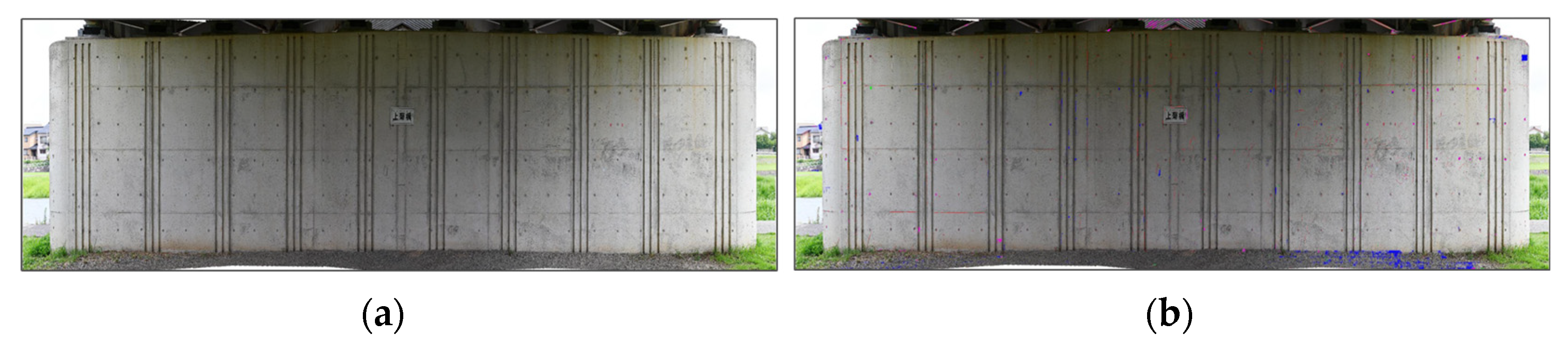
Images compositing photographs of pier P2 of the bridge and damage detection images were prepared in advance on the cloud (
Figure 4). The engineer in the simulated office then downloaded the images from the cloud to verify damage.
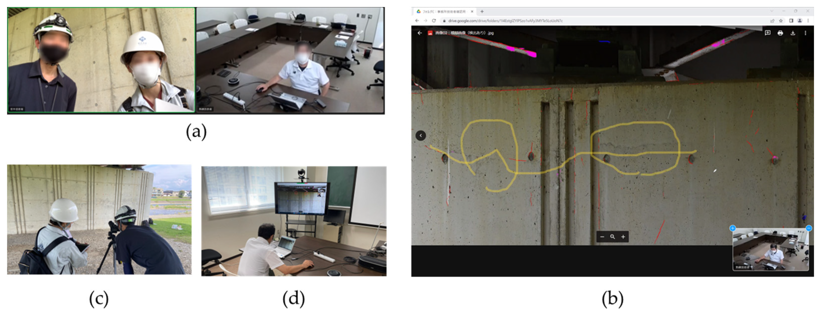
The novice engineer at the bridge site and the skilled engineer in the simulated office communicated in real time using the Zoom online conference system (
Figure 5a). Furthermore, the images of damage detection results were shared using the image sharing function of Zoom, and an onscreen writing function (annotation function) was used to mutually verify damaged areas (
Figure 5b). Finally, the bridge engineer at the office instructed the novice engineer at the bridge site to take additional close-up photographs of damaged areas; here, two photographs were taken onsite (
Figure 5c). The camera used was the same as that used for taking photographs of the piers in advance, and the remotely located engineer verified the additional images uploaded to the cloud.
5. Bridge Engineer Evaluation of Real-Time Remote Inspection
5.1. Bridge Engineer Interview
The subject of the simulation experiment is a novice third-year engineer from a general construction consulting company in Prefecture I. The engineer is actually involved in the bridge inspection work. The skilled engineer similarly works at a general construction consulting company, and he or she is a doctoral degree holder (engineering), professional in construction (steel and concrete), and a concrete diagnostician.
The details of the interview for both engineers following the experiment are summarized below.
Mutual verification of damage conditions between the bridge site and a remote location is possible by pinpointing damaged areas through the online conference system’s image sharing and writing functions.
It is possible to accurately ascertain damage conditions by delegating tactile and audible inspections to a novice engineer, even if damage conditions cannot be determined from images.
Even though the inspections are conducted by a novice engineer, onsite inspections can be reliably verified by a skilled engineer, provided there is real-time remote inspection support.
Even if a skilled engineer is needed for multiple bridge inspections with overlapping schedules, remote support allows inspection without the need to actually visit bridge sites, thus providing labor savings for inspection work.
In addition, the following opinions were received on bridge inspections using remote inspection, robots, and AI.
Inspections by remote inspection support, robots, or AI result in an increase in efficiency if they are used according to the bridge’s soundness. The latest technology may be used on bridges with high soundness. However, bridges with advanced damage require close visual, tactile, and audible inspection. Rather than inspecting all bridge sections with remote inspection support, it is more feasible to identify locations and sections that cannot be usually identified by an engineer at bridge sites and then have them verified by a skilled engineer.
5.2. Proposal of Inspection Based on Bridge Soundness
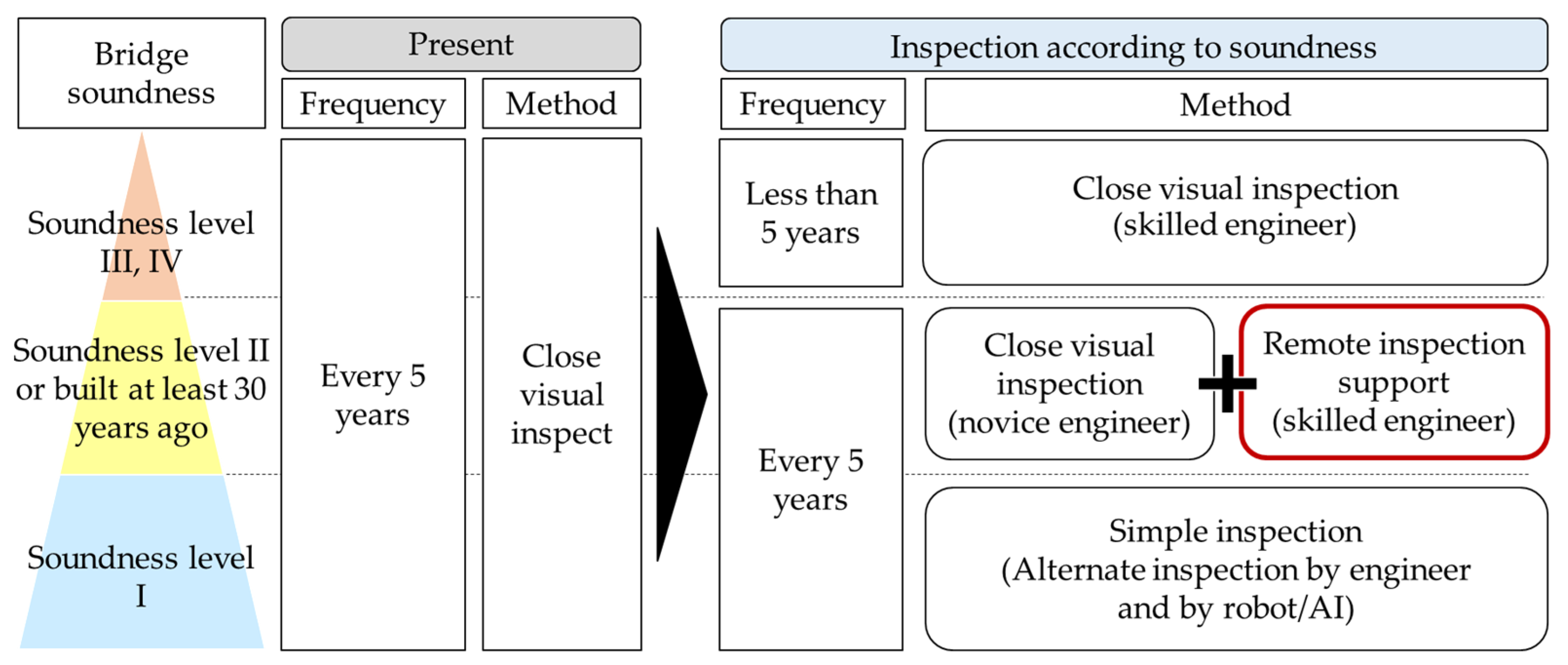
We suggest the use of remote inspection support based on the information obtained through the interview with the engineer. Currently, a close visual inspection once every five years is mandatory, regardless of the soundness of the bridge. However, inspection operations and cost may vary according to the soundness. For that reason that we are presently facing a shortage of engineers, we believe that rather than allocating a limited number of engineers to all bridge inspections, labor savings might be possible through optimal human resource allocation to bridges that require skilled engineers. Therefore, we conducted inspections based on bridge soundness (
Figure 6).
Bridges with level I soundness experienced relatively less damage, which simplifies regular inspection. Inspections are alternately conducted by engineers and by robots and AI, every five years. Furthermore, significant labor savings may be achieved with the decrease in the number of items to be inspected. For example, the damage items for simple inspections by engineers are as listed in
Table 2 of the Road and Bridge Inspection Guidelines [
3]: corrosion, cracks, breaks, fissures, deck cracks, functional failure of bearings, and others (
Table 3). In addition, the inspections by robots or AI only cover damage that can be determined from the images.
Soundness level II indicates that there is no impairment of bridge function, but measures should be taken. The damage progresses and reaches the stage where the soundness level III bridge function is impaired. Thus, inspection by engineers is desirable. In addition, in bridges that were built at least 30 years ago, soundness level I falls below 42% (
Figure 7), and in such cases, inspection by engineers is desirable in light of the risk of damage.
Therefore, during inspections of bridges with soundness level II or built 30 years ago, a combination of close visual inspection at the bridge site and remote inspection support should be integrated. With remote inspection support, a skilled engineer is kept on standby at an office, and he or she provides further support in unclear cases or when further verification is required at bridge sites. The skilled engineer at the office need not go to the bridge site, and they can support multiple sites on the same day. Furthermore, if there was unclear information at a bridge site and there was no engineer available on that particular day, the skilled engineer would go to the bridge site on another day. However, this is no longer necessary, resulting in significant labor savings.
Bridges with soundness levels III and IV may be developing or have already developed functional impairments and, therefore, require close visual inspection by a skilled engineer. In this system, engineers with a high degree of expertise primarily focus on at-risk bridges, to the extent that work by skilled engineers on soundness level I and II bridges is significantly reduced. It is predicted that bridges with soundness levels III and IV will also increase in the future with the number of aging bridges. It is desirable that skilled engineers are not sent onsite for all bridges and that they primarily focus on those that require careful inspection.
We calculated the number of bridges from their soundness and years of construction based on
Figure 7 to estimate the number of labor saving bridges (
Table 4). There are about 60,000 soundness level I bridges subject to the simple inspection as of March 2022. Furthermore, there are about 600,000 bridges with soundness level II or that were built 31 years ago. If remote inspection support is provided for 600,000 bridges, inspection work will be labor-saving for about 80% of bridges.
However, because the current bridge inspection system in principle requires close visual inspection of all bridges, simple inspection for soundness level I is not permitted among the inspection methods for each soundness level shown in
Figure 7. In addition, even with close visual inspection and remote inspection support by a skilled engineer, if limited damage can be verified remotely by images and tactile and audible inspection by a skilled engineer is required, then they will be sent to the bridge site later.
6. Conclusions and Pending Issues
In this section, we study the operability of real-time remote inspection in order to realize remote inspection support. We measured the image upload time for 5G and 4G communication to share a large volume of bridge images. With bridge engineers as the subjects, we conducted a simulation experiment wherein bridge images were uploaded from a bridge site, and then, a skilled engineer at the simulated office instructed a novice engineer at the bridge site. Furthermore, we conducted an interview with engineers on the operation of remote inspection support, and we proposed inspection strategies based on each soundness level to achieve labor savings for inspection work. The outcomes of the study are summarized as follows:
To measure the image upload time for 5G and 4G networks, we measured the time to upload 196 MB of pier images. The upload time in the 5G area around the target bridge was 36.8 s while that with 4G was 57.4 s. There was a difference of approximately 20 s in the upload time between 5G and 4G. Worktime could be shortened by uploading images using 5G.
In the simulation experiment of real-time remote inspection support, images were shared via a cloud server, and the bridge site and simulated office communicated through an online conference system, Zoom. The engineers verified damaged areas in bridge images using the image sharing and writing functions of the online conference system.
In the remote inspection support simulation experiment, it was possible to delegate required tactile or audible inspections to a bridge site engineer by connecting to the remote location in real time and, in doing so, determining the damage.
In an interview with bridge engineers, it was determined that real-time remote inspection support is effective when a skilled engineer cannot travel to the bridge site. In conventional close visual inspection, if a skilled engineer is not present at a bridge site, they verify the damage after the onsite engineer returns to the office after the inspection work, and the skilled engineer goes to the bridge site on a different day. Due to the travel times to bridge sites that are located far away can be especially long, communication in real time may help achieve potential labor savings in terms of engineer travel times.
We thus suggest inspection based on soundness, according to the opinions of engineers. If the soundness level is I, then inspections alternate every five years between simple inspections by engineers and inspections by robots or AI. For a bridge with soundness level II, or if at least 30 years have elapsed since it was built, a combination of close visual inspection at the bridge site and remote inspection support from a skilled engineer is used. Bridges with soundness levels III or IV shall receive a close visual inspection from a skilled engineer.
The limitations of the study are described next. The bridge is located in a 5G area. A limited number of bridge sites are within the 5G network areas. In a 4G area, uploading is more time-consuming than with 5G, and thus, inspection operations need to be modified; here, uploading only images of sections requiring verification by a skilled engineer rather than all sections of a bridge. In addition, the bridge field, which is a 5G area, is limited, and in this study, upload experiments were conducted at only one bridge site. In the future, as the 5G area expands, it will be required to experiment with uploading images at more bridge sites.
The communication through the 5G network speed resembles the communication over a wireless section from a terminal to a base station and is the same as 4G across a wired section from a base station to a switch, Internet, and a cloud server. Furthermore, because there are mechanisms in place on Internet-based cloud servers to control high-volume communication, the use of an MEC server that can maximize 5G without any such restrictions should be considered.
In the remote inspection support simulation experiment, we only inspected one side of a pier. Hence, the time and work required to upload images of all of a bridge’s sections and verify damage from a remote location should be verified. A system for image compositing and damage detection will be built in the future work. We suggest that inspection according to soundness provides labor savings through simple inspection of bridges with little damage at soundness level I. However, simple inspection is not permitted under the current system. It also needs to identify the damage types and degrees that robots and AI can determine. We focused on four damages, but it is necessary to increase the detection damage.
Remote testing support does not cover all damages. In remote inspection support, when a skilled engineer determines that tactile or auditory inspection is necessary by himself, it is necessary to go to the bridge site on another day for inspection.
Author Contributions
Conceptualization, M.Y., M.F., T.F. and T.S.; methodology, M.Y., M.F., T.F. and T.S.; software, T.S. and T.F.; validation, M.Y., T.S. and T.F.; formal analysis, M.Y. and T.F.; investigation, H.I., K.T., T.I., T.S. and T.F.; resources, H.I., K.T., T.I., T.S. and T.F.; data curation, M.Y., T.S. and T.F.; writing—original draft preparation, M.Y.; writing—review and editing, M.Y. and M.F.; visualization, M.Y.; supervision, M.F. and J.T.; project administration, M.F.; funding acquisition, M.F. All authors have read and agreed to the published version of the manuscript.
Funding
This research received no external funding.
Conflicts of Interest
The authors declare no conflict of interest.
References
- Ministry of Land, Infrastructure, Transport and Tourism Road Bureau, Bridge Periodic Inspection Procedures. Available online: https://www.mlit.go.jp/road/sisaku/yobohozen/tenken/yobo3_1_6.pdf (accessed on 11 October 2022).
- Ministry of Land, Infrastructure, Transport and Tourism Road Bureau, Road Maintenance Annual Report (August 2022). Available online: https://www.mlit.go.jp/road/sisaku/yobohozen/pdf/r03/r03_09maint.pdf (accessed on 18 December 2022).
- Ministry of Land, Infrastructure, Transport and Tourism Road Bureau, Road and Bridge Inspection Guidelines (February 2019). Available online: https://www.mlit.go.jp/road/sisaku/yobohozen/tenken/yobo4_1.pdf (accessed on 11 October 2022).
- Ministry of Land, Infrastructure, Transport and Tourism, Inspection Support Technical Performance Catalog. Available online: https://www.mlit.go.jp/road/sisaku/inspection-support/pdf/11_1.pdf (accessed on 4 December 2022).
- Dang, J.; Matsuyama, T.; Chun, P.; Shi, J.; Matsunaga, S. A study on deep learning and accuracy improvement methods for automatic damage recognition in UAV images. AI Data Sci. 2020, 1, 596–605. [Google Scholar]
- Kimoto, K.; Wakahara, T.; Kaneuji, M.; Fujii, M.; Kuroda, T. Demonstration of bridge inspection robot technology for regional implementation—Eshima Ohashi Bridge Project. Infrastruct. Maint. Pract. 2022, 1, 115–124. [Google Scholar]
- Izumi, S.; Chun, P. Automatic crack detection by deep learning model using attention mechanism. AI Data Sci. 2021, 2, 545–555. [Google Scholar]
- Nakamura, H.; Yamamoto, T.; Aoshima, K. Development of automatic detection method of deterioration area aiming at labor saving of concrete bridge inspection. Infrastruct. Maint. Pract. 2022, 1, 386–393. [Google Scholar]
- Saito, S.; Fujiu, M.; Hukuoka, T. Proposal of remote Inspection method for labor saving of bridge inspection through adaptation of AI and VR technology to real bridges. Infrastruct. Maint. Pract. 2022, 1, 372–377. [Google Scholar]
- Ribeiro, D.; Santos, R.; Shibasaki, A.; Montenegro, P.; Carvalho, H.; Calçada, R. Remote inspection of RC structures using unmanned aerial vehicles and heuristic image processing. Eng. Fail. Anal. 2020, 117, 104813. [Google Scholar] [CrossRef]
- NTT DOCOMO, INC., PREMIUM 4G. Available online: https://www.docomo.ne.jp/area/premium_4g/?icid=CRP_AREA_to_CRP_AREA_premium_4g (accessed on 16 February 2023).
- Ministry of Internal Affairs and Communications. The 2020 White Paper on Information and Communications in Japan. Available online: https://www.soumu.go.jp/johotsusintokei/whitepaper/ja/r02/html/nd111310.html (accessed on 16 February 2023).
- Kimoto, K.; Matsuda, H. Verification of digital image resolution and visible crack width of concrete. J. Struct. Mater. Civ. Eng. 2019, 35, 53–54. [Google Scholar]
- Information-Technology Promotion Agency, Information Security White Paper. Available online: https://www.ipa.go.jp/files/000070313.pdf (accessed on 18 December 2022).
- Fukuoka, T.; Fujiu, M. A Competition of Crack Detection Result of Different Bridges with Different Models Trained by Fake Images. 2022, Volume 1, pp. 439–444. Available online: https://www.jstage.jst.go.jp/article/jsceim/1/1/1_439/_article/-char/en (accessed on 18 December 2022).
- Qin, Z.; Zheng, Z.; Qingquan, L.; Xianbiao, Q.; Qian, W.; Song, W. DeepCrack: Learning Hierarchical Convolutional Features for Crack Detection. IEEE Transactionson Image Process. 2019, 28, 1498–1512. [Google Scholar]
- Badrinarayanan, V.; Kendall, A.; Cipolla, R. SegNet: A Deep Convolutional Encoder-Decoder Architecture for Image Segmentation. IEEE Trans. Pattern Anal. Mach. Intell. 2017, 39, 2481–2495. [Google Scholar] [CrossRef]
| Disclaimer/Publisher’s Note: The statements, opinions and data contained in all publications are solely those of the individual author(s) and contributor(s) and not of MDPI and/or the editor(s). MDPI and/or the editor(s) disclaim responsibility for any injury to people or property resulting from any ideas, methods, instructions or products referred to in the content. |
© 2023 by the authors. Licensee MDPI, Basel, Switzerland. This article is an open access article distributed under the terms and conditions of the Creative Commons Attribution (CC BY) license (https://creativecommons.org/licenses/by/4.0/).


 ,
, 

